EP1376770A1 - A connector and a method of assembling it - Google Patents
A connector and a method of assembling it Download PDFInfo
- Publication number
- EP1376770A1 EP1376770A1 EP02026303A EP02026303A EP1376770A1 EP 1376770 A1 EP1376770 A1 EP 1376770A1 EP 02026303 A EP02026303 A EP 02026303A EP 02026303 A EP02026303 A EP 02026303A EP 1376770 A1 EP1376770 A1 EP 1376770A1
- Authority
- EP
- European Patent Office
- Prior art keywords
- retainer
- terminal fitting
- connector housing
- locking
- connector
- Prior art date
- Legal status (The legal status is an assumption and is not a legal conclusion. Google has not performed a legal analysis and makes no representation as to the accuracy of the status listed.)
- Granted
Links
- 238000000034 method Methods 0.000 title claims description 7
- 239000003381 stabilizer Substances 0.000 claims abstract description 35
- 238000003780 insertion Methods 0.000 claims description 11
- 230000037431 insertion Effects 0.000 claims description 11
- 230000013011 mating Effects 0.000 claims description 8
- 230000002452 interceptive effect Effects 0.000 claims description 2
- 210000000078 claw Anatomy 0.000 description 6
- 238000006073 displacement reaction Methods 0.000 description 2
- 229920003002 synthetic resin Polymers 0.000 description 2
- 239000000057 synthetic resin Substances 0.000 description 2
- 241001046947 Ectropis obliqua Species 0.000 description 1
- 238000005452 bending Methods 0.000 description 1
- 238000010276 construction Methods 0.000 description 1
- 230000001419 dependent effect Effects 0.000 description 1
- 239000000428 dust Substances 0.000 description 1
- 230000000694 effects Effects 0.000 description 1
- 238000004049 embossing Methods 0.000 description 1
- 238000012423 maintenance Methods 0.000 description 1
- 239000000463 material Substances 0.000 description 1
- 239000002184 metal Substances 0.000 description 1
Images






Classifications
-
- H—ELECTRICITY
- H01—ELECTRIC ELEMENTS
- H01R—ELECTRICALLY-CONDUCTIVE CONNECTIONS; STRUCTURAL ASSOCIATIONS OF A PLURALITY OF MUTUALLY-INSULATED ELECTRICAL CONNECTING ELEMENTS; COUPLING DEVICES; CURRENT COLLECTORS
- H01R13/00—Details of coupling devices of the kinds covered by groups H01R12/70 or H01R24/00 - H01R33/00
- H01R13/40—Securing contact members in or to a base or case; Insulating of contact members
- H01R13/42—Securing in a demountable manner
- H01R13/436—Securing a plurality of contact members by one locking piece or operation
- H01R13/4361—Insertion of locking piece perpendicular to direction of contact insertion
- H01R13/4362—Insertion of locking piece perpendicular to direction of contact insertion comprising a temporary and a final locking position
Definitions
- the present invention relates to a connector and to a method for assembling it.
- Connectors of so-called side-retainer type are known in which a retainer mount hole is formed in one side surface of a connector housing and a retainer is pushed into this hole to lock terminal fittings.
- the retainer is obliquely pushed in some of this type of connectors and one example is disclosed in Japanese Unexamined Patent Publication No. 6-151002.
- This connector includes a retainer insertable into cavities formed in a connector housing obliquely from behind. Even if a terminal fitting is left insufficiently inserted without reaching a proper depth, such a terminal fitting can be pushed from behind and brought to a proper depth position in the process of properly mounting the retainer.
- Locking projections are provided on side surfaces of the connector housing and the retainer can be held at a proper mount position by engaging these locking projections with locking holes formed in the surfaces of the retainer facing the side surfaces of the connector housing.
- the retainer is locked by the engagement of the locking holes and the locking projections in the connector disclosed in the above publication and there is said to be practically no problem in preventing the retainer from being returned.
- the miniaturization of connectors is desired. Specifically, as the connector is miniaturized, it becomes more difficult to provide a sufficient area of engagement between the retainer and the terminal fittings in depth direction. In such circumstances, it is desirable to suppress the displacement of the retainer in returning direction as much as possible.
- the present invention was developed in view of the above problem and an object thereof is to more securely prevent terminal fittings from coming out.
- a connector comprising:
- the retainer mount hole is formed at an intermediate longitudinal position of the connector housing so as to be open to three sides thereof, only.
- a portion of the retainer to be held substantially in sliding contact with the connector housing when the retainer is pushed into the retainer mount hole is formed with the guiding portion for obliquely guiding the retainer with respect to the inserting direction of the terminal fitting.
- the cavity is formed substantially along a connecting direction of the connector housings.
- a locking portion resiliently deformably formed to engage the terminal fitting when the terminal fitting is inserted substantially to a proper depth position, wherein the locking portion doubly locks the terminal fitting in cooperation with the retainer.
- a connector comprising:
- the terminal fitting at least partly inserted into the cavity preferably from behind is locked by the locking portion upon reaching the proper depth position. Thereafter, when the retainer is pushed into the retainer mount hole, it is obliquely displaced while being guided by the guiding portion, and mounted. As a result, the retainer locks the terminal fitting, which is then preferably doubly locked in cooperation with the locking portion.
- the retainer is displaced from an initially fitted position at the rear side of the retainer mount hole to the front side of the retainer mount hole along the direction oblique to the inserting direction of the terminal fitting and reaches the final mount position.
- the retainer pushes the terminal fitting to the proper depth position while being obliquely moved and locks the terminal fitting in a proper state.
- the retainer If a force acts on the terminal fitting in withdrawing direction with the terminal fitting locked by the retainer, the retainer tries to move in its withdrawing direction, i.e. oblique backward direction. In such a case, since the retainer locking portion is provided with the biting portion, the biting portion bites in the opposed surface of the retainer if the retainer tries to move in the withdrawing direction. Thus, the displacement of the retainer can be securely prevented.
- the retainer locking portion comprises a stabilizer which permits the insertion of the retainer or terminal fitting when the terminal fitting is inserted in a proper posture into the cavity while interfering with a wall surface of the cavity to hinder the insertion of the retainer or terminal fitting when the terminal fitting is inserted in a posture different from the proper orientation.
- biting portion does not complicate the construction of the terminal fitting since it is formed using an existing structure called stabilizer.
- the retainer locking portion comprises a projection formed to stand adjacent to the stabilizer and engageable with the retainer together with the stabilizer preferably to lock the retainer, and a rear end of the projection is a surface arranged at an angle different from 0° or 180°, preferably substantially normal to the inserting direction or a vertical surface with which the opposed or cooperating surface of the retainer is engageable.
- the pointed end of the stabilizer is held substantially in point contact with the retainer and the projection is held in surface contact with the retainer along vertical direction. Since the terminal fitting can have a wider contact area with the retainer as compared to a case where only the stabilizer is provided, the terminal fitting can be more securely prevented from shaking.
- the connector housing comprises a plurality of cavities arranged at two or more stages, the retainer mount hole communicating with the cavities arranged at the two or more stages, and wherein the retainer can lock the terminal fittings into the cavities arranged at the two or more stages.
- a method of assembling a connector in particular according to the invention or an embodiment thereof, comprising a connector housing connectable with a mating connector housing, comprising the following steps:
- the retainer mount hole is formed at an intermediate longitudinal position of the connector housing so as to be open to three sides thereof, only, the retainer mount hole being preferably substantially closed by the retainer being pushed into the retainer mount hole.
- FIGS. 1 to 14 identified by 1 is a connector housing integrally or unitariyl made e.g. of a synthetic resin material, and a lock arm 2 in the form of a beam preferably supported only at one end is resiliently deformably provided substantially in the middle of the upper surface of the connector housing 1.
- This lock arm 2 is resiliently engaged or engageable with an unillustrated mating connector housing to lock the two connector housings in a connected state.
- One or more, preferably a plurality of cavities 3 are arranged substantially along widthwise direction at one or more, e.g. at two upper and lower stages inside the connector housing 1.
- the respective cavities 3 penetrate the connector housing 1 along forward and backward or longitudinal directions, and terminal fittings 25 can be at least partly ccommodated therein by being inserted in the inserting direction ID, preferably from behind.
- Locking portions 5 for partly locking the terminal fittings 25 are provided at the front sides of the bottom surfaces of the respective cavities 3.
- Each locking portion 5 preferably extends substantially forward or along the inserting direction ID and is supported preferably only at one end and resiliently deformable along vertical direction or a direction at an angle different from 0° or 180°, preferably substantially normal to the inserting direction ID.
- the locking portion 5 is resiliently deformed downward or outwardly as the terminal fitting 25 passes it. After the passage, the locking portion 5 is at least partly resiliently restored to engage a locking projection 27 formed on the terminal fitting 25 with the front end surface of the locking portion 5, thereby preventing the terminal fitting 25 from coming out.
- a projection inserting groove 6 is formed to extend along forward and backward or longitudinal directions preferably in the substantially middle of the upper surface of each locking portion 5, thereby reducing a degree of downward resilient deformation of the locking portion 5 during the passage of the terminal fitting 25. In other words, the height of the entire connector is or can be made shorter by reducing the heights of clearances between the locking portions 5 and the bottom surfaces of the cavities 3.
- the terminal fitting 25 is described.
- the terminal fitting 25 is formed preferably by bending, folding and/or embossing a metal plate stamped or cut out into a specified (predetermined or predeterminable) development, and is provided with a main portion 26 connectable with a mating terminal fitting (unillustrated male terminal fitting) at its front part and a barrel portion 30 used for the connection with a wire 31 at its rear end.
- the main portion 26 has a substantially box shape, and a tab of the male terminal fitting is at least partly insertable thereinto.
- the bottom wall (wall facing the locking portion 5) preferably has a double-wall structure in which an inner wall 50 and an outer wall 51 are substantially placed at least partly one over the other.
- the outer wall 51 is divided into a front or first portion 54 and a rear or second portion 55 by forming a cut-away or recess portion 52 preferably at a substantially longitudinal middle portion preferably over the substantially entire width.
- the locking portion 5 can at least partly enter the cut-away portion 52 preferably over its substantially entire length and engage a front cut end surface 53 of the cut-away portion 52.
- the front cut end surface 53 of the cut-away portion 52 which is a surface engageable with the locking portion 5 is inclined upward or outward to the back or away from a mating side or in a withdrawing direction preferably over a substantially entire area.
- a widthwise center portion of the front portion 54 of the outer wall 51 is embossed or cut and bent at the rear end to form the aforementioned locking projection 27, which is engageable with the locking portion 5.
- the rear end of the locking projection 27 overhangs backward (or is undercut) preferably substantially along the inclination of the front cut end surface 53 of the cut-away portion 52 and projects more backward than the rear end of the front portion 54 of the outer wall 51.
- a substantially widthwise center portion of the rear portion 54 of the outer wall 51 is embossed or cut and bent at the rear end to form a projection 28 engageable with a retainer 35 to be described later.
- the projection 28 is provided on the substantially same axis of the locking projection 27, preferably projects up to the substantially same height as the locking projection 27 and is at least partly insertable into the projection inserting groove 6.
- the rear end of the projection 28 vertically stands or projects at an angle different from 0° or 180°, preferably substantially normal to the inserting direction ID or longitudinal direction of the terminal fitting 25 so as to be brought substantially into surface contact with a front end surface 46A of the bottom wall of a window 37 or a front end surface 46B (both 46A and 46B are described in detail later) of the upper wall of a retainer main body 36 which substantially is an opposed or facing or cooperating surface of the retainer 35.
- the contact surface 46A, 46B of the retainer 35 is held substantially in contact with the projection 28 and the rear end of the rear portion 55 where the projection 28 is formed along depth direction and with the projections 28 and the stabilizer 29 (retainer locking portion) to be described next along widthwise direction.
- the stabilizer 29 is preferably in the form of a substantially flat plate and provided at the side of the projection 28.
- the stabilizer 29 stands on the rear portion 55 of the outer wall 51 and preferably has a length substantially equal to that of the projection 28.
- This stabilizer 29 can be moved forward in an escaping groove 4 formed at one corner of the bottom surface of each cavity 3. Since the stabilizer 29 is not aligned with the escaping groove 4 when the terminal fitting 25 is inserted upside down or improperly, the upside-down or improper insertion of the terminal fitting 25 can be prevented or detected.
- the rear end of the stabilizer 29 preferably is inclined or slanted or rounded upward to the back so that the projecting end thereof is pointed or converging.
- the pointed end of the stabilizer 29 serves as a biting portion 56 which can bite in the opposed or cooperating surface of the retainer 35 to hold or maintain the retainer 35 at a full locking or second position.
- a retainer mount hole 10 into which the retainer 35 is preferably mountable is formed in the surface of the connector housing 1 opposite from the one where the lock arm 2 is provided.
- the retainer mount hole 10 is formed in an area of the connector housing 1 over three surfaces including a surface facing in a pushing direction PD of the retainer 35 (bottom surface in FIG. 1) and surfaces (front and back surfaces in FIG. 1, hereinafter referred to as side surfaces of the connector housing 1) thereof substantially normal to the former surface. Accordingly, the retainer mount hole 10 is provided at an intermediate longitudinal position of the connector housing 1 and is open at three sides. Further, the retainer mount hole 10 has such a depth as to expose the respective cavities 3 at the upper stage, whereby the respective upper and lower cavities 3 are divided into front and rear sections.
- the opening edges of the respective cavities 3 all preferably extend substantially vertically or normal to the inserting direction ID at the front surface of the retainer mount hole 10 while being inclined downward to the back or arranged at an angle different from 0°, 90° or 180° or oblique with respect to the inserting direction ID of the terminal fittings 25 at the rear surface thereof.
- each side surface of the connector housing 1 above and behind the side opening of the retainer mount hole 10 is slightly recessed or slanted with respect to a front area of this side surface, thereby forming a stepped or slanted surface 13.
- a rib-shaped locking projection 14 (as a preferred guiding portion) extending substantially along the inclined side of the side opening of the retainer mount hole 10 is formed on this stepped or slanted surface 13.
- the locking projections 14 mainly function to stabilize the posture of the retainer 35 while the retainer 35 is pushed into the retainer mount hole 10 of the connector housing 1.
- a beveled portion 15 is entirely formed on one side (toward the retainer mount hole 10) of the outer surface of each locking projection 14 with respect to the longitudinal center line thereof, so that the locking projection 14 can be smoothly fitted into a corresponding guide groove 42 (guiding portion) of the retainer 35.
- the upper and lower end surfaces of each locking projection 14 are formed into horizontal surfaces 16, and a vertical surface 17 substantially continuous with the upper horizontal surface 16 is formed at the upper end.
- a push-preventing projection 18 is formed on a downward extension line from each locking projection 14. With the retainer 35 partly locked (state or partial locking or first position shown in FIGS. 7 and 8), the push-preventing projections 18 are engaged with the bottom ends of the guide grooves 42 of the retainer 35, thereby preventing the retainer 35 from being inadvertently pushed to a full locking or second position.
- a shake-restricting portion 19 for suppressing the shake of the retainer 35 at the full locking or second position projects above the locking projection 14 on each stepped surface 13.
- Each shake-restricting portion 19 extends substantially horizontally along forward and backward or longitudinal directions and has the upper edge thereof cut away in a stepped manner so that a rear part is slightly narrower.
- This cut-away portion 20 is used to insert a jig or the like to open the side plates 14 wider when the retainer 35 is moved between the partial locking or first position and the full locking or second position.
- a slanted surface 23 is formed over the entire bottom edge of each shake-restricting portion 19.
- a hooking piece 21 partly forming the locking means of the present invention projects before each shake-restricting portion 19.
- the hooking pieces 21 are formed such that the upper edges thereof are substantially continuous with the upper edges of the corresponding shake-restricting portions 19, and are engaged or engageable with locking claws 45 of the retainer 35 when the retainer 35 is fully locked so as to hold the retainer 35 at the full locking or second position.
- the front surfaces of the hooking pieces 21 are formed into slanted or inclined surfaces 22 inclined forward toward the above, so that the locking claws 45 can be smoothly moved onto the hooking pieces 21.
- the retainer 35 is made e.g. of a synthetic resin similar to the connector housing 1, and is comprised of the retainer main body 36 at least partly fittable into the retainer mount hole 10 and a pair of side plates 40 bulging out at the opposite widthwise ends or end portions of the retainer main body 36.
- the retainer main body 36 is formed with the same number of windows 37 as the cavities 3 at each stage of the connector housing 1.
- the respective windows 37 are substantially alignable with the cavities 3 at the lower stage of the connector housing 1.
- the front opening edges of the respective windows 37 extend vertically so as to be alignable with the rear opening edges of the front sections of the respective cavities 3 divided by the retainer mount hole 10, whereas the rear opening edges thereof are so inclined as to substantially conform to the inclination of the front opening edges of the rear sections of the cavities 3.
- front parts and the upper surfaces of the retainer main body 36 are located at the substantially same height as the bottom surfaces of the corresponding cavities 3 when the retainer 35 is partly locked so as to permit the insertion and withdrawal of the terminal fittings 25 in the insertion direction ID.
- front end surfaces 46A of the bottom walls of the windows 37 and front end surfaces 46B of the upper walls of the retainer main body 36 are engageable with the projections 28 of the terminal fittings 2 to doubly lock the terminal fittings 25 in cooperation with the locking portions 5.
- Stabilizer inserting grooves 39 for permitting the passage of the stabilizers 29 of the terminal fittings 25 are formed in the bottom surfaces of the windows 37 and the upper surface of the retainer main body 36.
- the respective stabilizers 29 and the stabilizer inserting grooves 39 are vertically shifted or displaced along the pushing direction PD from each other when the retainer 35 is moved to the full locking or second position, the rear end surfaces of the stabilizers 29 are or can be engaged with the wall surface of the retainer 35 located below the front ends of the stabilizer inserting grooves 39.
- the opposite side plates 40 of the retainer 35 have such a spacing corresponding to the one between the opposite side surfaces of the connector housing 1 and are deformable in such opening directions (or away from the connector housing 1) as to widen the spacing.
- the opposite side plates 40 are so dimensioned as to substantially close side openings of the retainer mount hole 10 and face specified (predetermined or predeterminable) areas of the corresponding stepped surfaces 13 when the retainer 35 is fully locked.
- the thickness of the side plates 40 preferably is substantially equal to the depth of the stepped surface from the outer side surfaces of the connector housing 1, so that the side plates 40 are substantially in flush with the corresponding outer surfaces of the connector housing 1 when the retainer 35 is fully locked.
- the side plates 40 of the retainer 35 preferably serve also as the outer walls of the side portions of the connector housing 1.
- a thick operable portion 41 vertically or outwardly extends on the outer surface of the rear part of each side plate 40, and the bottom end thereof projects from the bottom surface of the retainer 35.
- each side plate 40 is formed with a though guide groove 42 behind the retainer main body 36.
- Each guide groove is formed to have the substantially same inclination as the rear opening edges of the respective windows 37 of the retainer 35, i.e. the front opening edges of the rear sections of the respective cavities 3 of the connector housing 1, and a bottom portion thereof is located in the operable portion 41.
- the guide grooves 42 have a width substantially equal to the shorter width (or width substantially normal to the pushing direction PD) of the locking projections 14, and the opposite ends thereof are so shaped as to substantially conform to the shapes of the opposite ends of the locking projections 14.
- the guide grooves 42 are engageable with both the locking projections 14 and the push-preventing projections 18 at their opposite ends and hold the retainer 35 at the partial locking or first position in this state. While the retainer 35 is moved from the partial locking or first position to the full locking or second position, the side plates 40 are moved onto the push-preventing projections 18 in order to bring the push-preventing projections 18 out of the guide grooves 42.
- the projecting distance of the locking projections 14 is larger than that of the push-preventing projections 18 and is set at a value sufficient to keep the locking projections 14 engaged with the guide grooves 42 even if the side plates 40 are deformed to open wider. In this way, the retainer 35 reaches the fully locked state by moving the locking projections 14 toward the bottom ends of the guide grooves 42.
- a restricting recess 43 into which the corresponding shake-restricting portion 19 is at least partly fittable is formed above the guide groove 42, and slanted surfaces 44 are formed on the upper and lower edges of the restricting recess 43.
- the restricting recess 43 extends from a substantially middle position of the side plate 40 to the rear end along longitudinal direction while extending from the upper end of the guide groove 42 to the upper end of the side plate 40 substantially along height direction (or a direction substantially normal to the inserting direction ID), thereby having a substantially rectangular shape.
- the retainer 35 When the retainer 35 is partly locked, the upper edges of the shake-restricting portions 19 and those of the restricting recesses 43 are held at such a height where they are substantially aligned with each other and a specified (predetermined or predeterminable) clearance is defined between the lower edges of the shake-restricting portions 19 and those of the restricting recesses 43.
- the retainer 35 When the retainer 35 is fully locked, the tapered surfaces 23 at the lower edges of the shake-restricting portions 19 are substantially aligned with and held in contact with the slanted surfaces 44 at the lower edges of the restricting recesses 43, thereby preventing the retainer 35 from making upward shaking movements.
- the restricting recesses 43 extend further forward, and the locking claws 45 (forming preferred locking means together with the hooking pieces 21) are formed above these extended sections.
- the locking claws 45 are located substantially at the same height as the hooking pieces 21 of the connector housing 1 and face them with the retainer 35 partly locked, whereas they move over the slanted surfaces 22 of the hooking pieces 21 to engage the upper edges of the hooking pieces 21 when the retainer 35 is fully locked, thereby holding the retainer 35 at the full locking or second position.
- a specified clearance 47 is defined between the front end of the retainer 35 and the front end of the retainer mount hole 10, so that the inserted states of the terminal fittings 25 (whether or not the terminal fittings 25 are inserted) can be confirmed through this clearance 47 from the outside of the connector housing 1.
- the retainer 35 preferably is transported to a site of connecting connectors while being integrally mounted at the partial locking or first position in the connector housing 1.
- the retainer 35 is mounted at the partial locking or first position by holding the opposite stepped surfaces 13 of the connector housing 1 from opposite sides by the side plates 40 of the retainer 35 while suitably opening the side plates 40, and fitting the locking projections 14 and the push-preventing projections 18 into the guide grooves 42. Since the locking projections 14 and the push-preventing projections 18 are engaged with the opposite ends of the guide grooves 42, the retainer 35 is positioned at the partial locking or first position while being prevented from its inadvertent movement to the full locking or second position.
- the specified clearances are defined between the bottom edges of the shake-restricting portions 19 and those of the restricting recesses 43 in this state.
- the terminal fitting 25 passes the retainer 35 and then the locking portion 5 upon being at least partly inserted into the cavity 3 in the inserting direction ID, preferably from behind.
- the locking projection 27 causes the locking portion 5 to undergo a necessary and minimum resilient deformation while being permitted to escape by the projection inserting groove 6.
- the locking projection 27 is at least partly engaged with the front end surface of the locking portion 5 by the at least partial resilient restoration of the locking portion 5.
- the terminal fittings 25 are at least partly inserted into all the cavities 3. Since the specified clearance 47 is defined between the front end of the retainer 35 and the retainer mount hole 10 with the retainer 35 partly locked, the insides of the cavities 3 can be seen therethrough. This can prevent the insertion of the terminal fittings 25 from being forgotten.
- the retainer 35 is strongly pushed by holding the operable portions 41. Then, portions of the retainer 35 near the bottom ends of the guide grooves 42 are deformed to move onto the push-preventing projections 18 and bring them out of the guide grooves 42, and the retainer 35 is pushed in the pushing direction PD obliquely upward or inwardly of the connector housing 1 while being guided by the engagement of the locking projections 14 and the guide grooves 42. Since the locking projections 14 are held substantially in sliding contact with the guide grooves 42 over a specified length during this time, the retainer 35 can be pushed in a stable posture without being inclined or tilted in clockwise direction in FIG. 7.
- the retainer 35 When the retainer 35 reaches the full locking or second position, the front end surfaces 46A of the bottom walls of the windows 37 and the front end surfaces 46B of the upper walls of the retainer main body 36 are engageable with the projections 28 of the terminal fittings 25 to doubly lock the terminal fittings 25 in cooperation with the locking portions 5 inside the connector housing 1.
- the locking projections 14 are engaged with the bottom ends of the guide grooves 42, but the push-preventing projections 18 are located outside the operable portions 41. Since the locking claws 45 move over the slanted surfaces 22 of the hooking pieces 21 and engage the upper edges of the hooking pieces 21 at this time, the retainer 35 is locked at the full locking or second position. Further, since the bottom edges of the shake-restricting portions 19 are engaged with those of the restricting recesses 43, the retainer 35 is prevented from making upward shaking movements.
- the front surface of the retainer main body 36 is substantially in abutment against the front surface of the retainer mount hole 10, whereby the retainer mount hole 10 is substantially closed by the retainer 35 without substantially leaving any clearance therebetween.
- the entrance of dust and the like into the cavities 3 can be prevented.
- the retainer 35 When a pulling force acts on the wire 31 connected with the terminal fitting 25 with the retainer 35 fully locked, the retainer 35 tries to move obliquely backward.
- the engagement of the guide grooves 42 and the locking projections 14 and that of the shake-restricting portions 19 and the restricting recesses 43 are set against the backward movement of the retainer 35.
- the biting portion 56 of the stabilizer 29 additionally bites in the front end surface 46A of the bottom wall of the corresponding window 37 of the retainer 35 or the front end surface 46B of the retainer main body 36.
- the backward movement of the retainer 35 can be more securely prevented.
- the projection 28 is provided as a portion of the terminal fitting 25 engageable with the retainer 35 in addition to the stabilizer 29 in this embodiment, only the stabilizer 29 may be used as the engageable portion by omitting the projection 28. However, if only the stabilizer 29 is provided, only a point contact with the retainer 35 is obtained since the biting portion 56 is a pointed end. In this respect, the terminal fitting 25 can be more stably held in this embodiment since the rear end of the projection 28 is formed into a vertical surface to be held in surface contact with the retainer 35, thereby increasing a contact area with the retainer 35.
- the terminal fittings 25 need to be withdrawn for maintenance or other reason. Then, the retainer 35 needs to be first returned to the partial locking or first position.
- a disengagement jig is or can be at least partly inserted into clearances inside the inner surfaces of the side plates 40 of the retainer 35, i.e. clearance between the operable portions 41 and the cut-away portions 20 to forcibly open the side plates 40 wider, and the retainer 35 is moved back obliquely downward in this state.
- the retainer 35 can be returned to the partial locking or first position.
- the terminal fitting 25 can be withdrawn if the locking portion 5 is disengaged therefrom using an other disengagement jig inserted from front of the connector housing 1 in this state.
- the retainer 35 can be moved forward in the retainer mount hole 10 while being moved from the partial lokking or first position to the full locking or second position.
- the retainer 35 can be guided to a specified position at the front end of the retainer mount hole 10 regardless of a variation in the fitted position of the retainer 35.
- the retainer 35 since the retainer 35 is guided by the engagement of the guide grooves 42 and the locking projections 14 while being moved from the partial locking or first position to the full locking or second position, it can be stably and smoothly pushed in the intended direction.
- the retainer 35 and the terminal fittings 25 are engaged in a proper positional relationship at the full locking or second position. Therefore, unlike the prior art, the function of the retainer 35 to detected the inserted states of the terminal fittings 25 can be securely fulfilled and the securely locked state can be obtained.
- the retainer mount hole 10 is open in the side surfaces of the connector housing 1 in this embodiment, these side openings are closed by the side plates 40 when the mounted retainer 35 reaches the full locking or second position.
- the side plates 40 of the retainer 35 also serve as the outer walls of the side portions of the connector housing 1 in this embodiment, there is an advantage that the entire connector can have a smaller widthwise dimension as compared to such connectors in which the retainer mount hole 10 is not open in the side surfaces and the side plates 40 of the retainer 35 are placed on the side surfaces of the connector housing 1.
- the cavities 3 arranged at the upper and lower stages in the connector are locked not by separate retainers prepared for the respective stages, but by one retainer at once.
- the number of parts and the number of operation steps can be reduced.
- a retainer mount hole 10 is open in a connector housing 1 from its bottom surface over to its opposite side surfaces, and a retainer 35 is obliquely pushed from a partial locking position to a full locking position.
- each terminal fitting 25 is provided with a projection 28 and a stabilizer 29 at the side of the projection 28.
- both the projection 28 and the stabilizer 29 are engaged with the retainer 35.
- the projecting end of the rear end of the stabilizer 29 is pointed, thereby forming a biting portion 56.
- the biting portion 56 bites in the retainer 35 to prevent the retainer 35 from returning.
Landscapes
- Connector Housings Or Holding Contact Members (AREA)
Abstract
Description
- The present invention relates to a connector and to a method for assembling it.
- Connectors of so-called side-retainer type are known in which a retainer mount hole is formed in one side surface of a connector housing and a retainer is pushed into this hole to lock terminal fittings. The retainer is obliquely pushed in some of this type of connectors and one example is disclosed in Japanese Unexamined Patent Publication No. 6-151002. This connector includes a retainer insertable into cavities formed in a connector housing obliquely from behind. Even if a terminal fitting is left insufficiently inserted without reaching a proper depth, such a terminal fitting can be pushed from behind and brought to a proper depth position in the process of properly mounting the retainer. Locking projections are provided on side surfaces of the connector housing and the retainer can be held at a proper mount position by engaging these locking projections with locking holes formed in the surfaces of the retainer facing the side surfaces of the connector housing.
- If a pulling force acts on a wire connected with the terminal fitting, a force of the same direction also acts on the retainer locking the terminal fitting. In such a case, if the connector is of the normal side retainer type, the retainer is not displaced in withdrawing direction even if the wire pulling force acts on the retainer since a retainer mounting direction is normal to the inserting direction of the terminal fittings. However, in the connector of the type in which the retainer is obliquely pushed as described above, if a pulling force acts on the wire, this pulling force is split into a component of force acting on the retainer in returning direction, trying to obliquely pull the entire retainer back.
- The retainer is locked by the engagement of the locking holes and the locking projections in the connector disclosed in the above publication and there is said to be practically no problem in preventing the retainer from being returned. However, there is room for improvement in this point under the recent circumstances where the miniaturization of connectors is desired. Specifically, as the connector is miniaturized, it becomes more difficult to provide a sufficient area of engagement between the retainer and the terminal fittings in depth direction. In such circumstances, it is desirable to suppress the displacement of the retainer in returning direction as much as possible.
- The present invention was developed in view of the above problem and an object thereof is to more securely prevent terminal fittings from coming out.
- This object is solved according to the invention by a connector according to
claim 1 and by a method for assembling a connector according to claim 9. Preferred embodiments of the invention are subject of the dependent claims. - According to the invention, there is provided a connector, comprising:
- a connector housing connectable with a mating connector housing,
- at least one cavity into which a terminal fitting is at least partly insertable in an inserting direction, preferably from behind, to be at least partly accommodated therein,
- a retainer mount hole which is so formed in the connector housing as to communicate with the cavity, and
- a retainer to be at least partly pushed into the retainer mount hole to engage a retainer locking portion formed at the terminal fitting, thereby locking the terminal fitting, wherein at least one of the retainer and the connector housing comprise a guiding portion for obliquely guiding the retainer toward or with respect to the inserting direction of the terminal fitting and pushing the terminal fitting to the proper depth position, in case the terminal fitting has not reached the proper insertion position, as the retainer is obliquely displaced, and
-
- According to a preferred embodiment of the invention, the retainer mount hole is formed at an intermediate longitudinal position of the connector housing so as to be open to three sides thereof, only.
- Preferably, a portion of the retainer to be held substantially in sliding contact with the connector housing when the retainer is pushed into the retainer mount hole is formed with the guiding portion for obliquely guiding the retainer with respect to the inserting direction of the terminal fitting.
- Further preferably, the cavity is formed substantially along a connecting direction of the connector housings.
- Most preferably, a locking portion resiliently deformably formed to engage the terminal fitting when the terminal fitting is inserted substantially to a proper depth position, wherein the locking portion doubly locks the terminal fitting in cooperation with the retainer.
- According to a further preferred embodiment of the invention, there is provided a connector, comprising:
- a connector housing connectable with a mating connector housing,
- a cavity which is formed along connecting directions of the connector housings and into which a terminal fitting is insertable from behind to be accommodated therein,
- a locking portion resiliently deformably formed to engage the terminal fitting when the terminal fitting is inserted to a proper depth position,
- a retainer mount hole which is so formed in the connector housing as to communicate with the cavity, and
- a retainer to be pushed into the retainer mount hole to engage a retainer lokking portion formed at the terminal fitting, thereby doubly locking the terminal fitting in cooperation with the locking portion, wherein a portion of the retainer to be held in sliding contact with the connector housing when the retainer is pushed into the retainer mount hole is formed with a guiding portion for obliquely guiding the retainer toward or with respect to an inserting direction of the terminal fitting and pushing the terminal fitting to the proper depth position as the retainer is obliquely displaced, and
-
- Accordingly, the terminal fitting at least partly inserted into the cavity preferably from behind is locked by the locking portion upon reaching the proper depth position. Thereafter, when the retainer is pushed into the retainer mount hole, it is obliquely displaced while being guided by the guiding portion, and mounted. As a result, the retainer locks the terminal fitting, which is then preferably doubly locked in cooperation with the locking portion.
- During the above mounting operation, the retainer is displaced from an initially fitted position at the rear side of the retainer mount hole to the front side of the retainer mount hole along the direction oblique to the inserting direction of the terminal fitting and reaches the final mount position.
- If the terminal fitting is left lightly inserted without reaching the proper depth position, the retainer pushes the terminal fitting to the proper depth position while being obliquely moved and locks the terminal fitting in a proper state.
- If a force acts on the terminal fitting in withdrawing direction with the terminal fitting locked by the retainer, the retainer tries to move in its withdrawing direction, i.e. oblique backward direction. In such a case, since the retainer locking portion is provided with the biting portion, the biting portion bites in the opposed surface of the retainer if the retainer tries to move in the withdrawing direction. Thus, the displacement of the retainer can be securely prevented.
- Preferably, the retainer locking portion comprises a stabilizer which permits the insertion of the retainer or terminal fitting when the terminal fitting is inserted in a proper posture into the cavity while interfering with a wall surface of the cavity to hinder the insertion of the retainer or terminal fitting when the terminal fitting is inserted in a posture different from the proper orientation.
- Accordingly, the biting portion does not complicate the construction of the terminal fitting since it is formed using an existing structure called stabilizer.
- Further preferably, the retainer locking portion comprises a projection formed to stand adjacent to the stabilizer and engageable with the retainer together with the stabilizer preferably to lock the retainer, and a rear end of the projection is a surface arranged at an angle different from 0° or 180°, preferably substantially normal to the inserting direction or a vertical surface with which the opposed or cooperating surface of the retainer is engageable.
- Accordingly, when the terminal fitting is engaged with the retainer, the pointed end of the stabilizer is held substantially in point contact with the retainer and the projection is held in surface contact with the retainer along vertical direction. Since the terminal fitting can have a wider contact area with the retainer as compared to a case where only the stabilizer is provided, the terminal fitting can be more securely prevented from shaking.
- Most preferably, the connector housing comprises a plurality of cavities arranged at two or more stages, the retainer mount hole communicating with the cavities arranged at the two or more stages, and wherein the retainer can lock the terminal fittings into the cavities arranged at the two or more stages.
- According to the invention, there is further provided a method of assembling a connector, in particular according to the invention or an embodiment thereof, comprising a connector housing connectable with a mating connector housing, comprising the following steps:
- at least partly inserting a terminal fitting into at least one cavity of the connector housing in an inserting direction, preferably from behind, to be at least partly accommodated therein,
- at least partly pushing a retainer into a retainer mount hole of the connector housing to engage a retainer locking portion formed at the terminal fitting, thereby locking the terminal fitting, wherein in the pushing step:
- the retainer is obliquely guided toward or with respect to the inserting direction of the terminal fitting,
- the terminal fitting is pushed to the proper depth position in case the terminal fitting has not reached the proper depth position, as the retainer is obliquely displaced, and
- a biting portion of the retainer locking portion having a pointed end facing toward a cooperating surface of the retainer bites in the cooperating surface of the retainer.
-
- According to a preferred embodiment of the invention, the retainer mount hole is formed at an intermediate longitudinal position of the connector housing so as to be open to three sides thereof, only, the retainer mount hole being preferably substantially closed by the retainer being pushed into the retainer mount hole.
- These and other objects, features and advantages of the present invention will become more apparent upon reading of the following detailed description of preferred embodiments and accompanying drawings. It should be understood that even though embodiments are separately described, single features thereof may be combined to additional embodiments.
- FIG. 1 is a front view of a connector housing,
- FIG. 2 is section of the connector housing,
- FIG. 3 is a rear view of the connector housing,
- FIG. 4 is bottom view of the connector housing,
- FIG. 5 is a side view of a retainer,
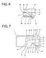
- FIG. 6 is a front view in section of the retainer,
- FIG. 7 is a front view of a connector when the retainer is partly locked,
- FIG. 8 is a section of the connector when the retainer is partly locked,
- FIG. 9 is a front view of a connector when the retainer is fully locked,
- FIG. 10 is a section of the connector when the retainer is fully locked,
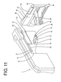
- FIG. 11 is a perspective view enlargedly showing portions of the connector near a locking projection and a guide groove,
- FIG. 12 is a side view of a terminal fitting,
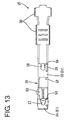
- FIG. 13 is a bottom view of the terminal fitting, and
- FIG. 14 is a section partly in section showing an engaged state of a stabilizer and the retainer.
-
- Hereinafter, one preferred embodiment of the present invention is described with reference to the accompanying drawings.
- In FIGS. 1 to 14, identified by 1 is a connector housing integrally or unitariyl made e.g. of a synthetic resin material, and a
lock arm 2 in the form of a beam preferably supported only at one end is resiliently deformably provided substantially in the middle of the upper surface of theconnector housing 1. Thislock arm 2 is resiliently engaged or engageable with an unillustrated mating connector housing to lock the two connector housings in a connected state. - One or more, preferably a plurality of
cavities 3 are arranged substantially along widthwise direction at one or more, e.g. at two upper and lower stages inside theconnector housing 1. Therespective cavities 3 penetrate theconnector housing 1 along forward and backward or longitudinal directions, andterminal fittings 25 can be at least partly ccommodated therein by being inserted in the inserting direction ID, preferably from behind. Lockingportions 5 for partly locking theterminal fittings 25 are provided at the front sides of the bottom surfaces of therespective cavities 3. Each lockingportion 5 preferably extends substantially forward or along the inserting direction ID and is supported preferably only at one end and resiliently deformable along vertical direction or a direction at an angle different from 0° or 180°, preferably substantially normal to the inserting direction ID. The lockingportion 5 is resiliently deformed downward or outwardly as the terminal fitting 25 passes it. After the passage, the lockingportion 5 is at least partly resiliently restored to engage a lockingprojection 27 formed on the terminal fitting 25 with the front end surface of the lockingportion 5, thereby preventing the terminal fitting 25 from coming out. Aprojection inserting groove 6 is formed to extend along forward and backward or longitudinal directions preferably in the substantially middle of the upper surface of each lockingportion 5, thereby reducing a degree of downward resilient deformation of the lockingportion 5 during the passage of theterminal fitting 25. In other words, the height of the entire connector is or can be made shorter by reducing the heights of clearances between the lockingportions 5 and the bottom surfaces of thecavities 3. - Here, the terminal fitting 25 is described. The
terminal fitting 25 is formed preferably by bending, folding and/or embossing a metal plate stamped or cut out into a specified (predetermined or predeterminable) development, and is provided with amain portion 26 connectable with a mating terminal fitting (unillustrated male terminal fitting) at its front part and abarrel portion 30 used for the connection with awire 31 at its rear end. Themain portion 26 has a substantially box shape, and a tab of the male terminal fitting is at least partly insertable thereinto. The bottom wall (wall facing the locking portion 5) preferably has a double-wall structure in which aninner wall 50 and anouter wall 51 are substantially placed at least partly one over the other. Theouter wall 51 is divided into a front orfirst portion 54 and a rear orsecond portion 55 by forming a cut-away orrecess portion 52 preferably at a substantially longitudinal middle portion preferably over the substantially entire width. When the terminal fitting 25 is inserted into thecavity 3, the lockingportion 5 can at least partly enter the cut-awayportion 52 preferably over its substantially entire length and engage a frontcut end surface 53 of the cut-awayportion 52. The front cutend surface 53 of the cut-awayportion 52 which is a surface engageable with the lockingportion 5 is inclined upward or outward to the back or away from a mating side or in a withdrawing direction preferably over a substantially entire area. - A widthwise center portion of the
front portion 54 of theouter wall 51 is embossed or cut and bent at the rear end to form theaforementioned locking projection 27, which is engageable with the lockingportion 5. The rear end of the lockingprojection 27 overhangs backward (or is undercut) preferably substantially along the inclination of the frontcut end surface 53 of the cut-awayportion 52 and projects more backward than the rear end of thefront portion 54 of theouter wall 51. - On the other hand, a substantially widthwise center portion of the
rear portion 54 of theouter wall 51 is embossed or cut and bent at the rear end to form aprojection 28 engageable with aretainer 35 to be described later. Theprojection 28 is provided on the substantially same axis of the lockingprojection 27, preferably projects up to the substantially same height as the lockingprojection 27 and is at least partly insertable into theprojection inserting groove 6. The rear end of theprojection 28 vertically stands or projects at an angle different from 0° or 180°, preferably substantially normal to the inserting direction ID or longitudinal direction of the terminal fitting 25 so as to be brought substantially into surface contact with afront end surface 46A of the bottom wall of awindow 37 or afront end surface 46B (both 46A and 46B are described in detail later) of the upper wall of a retainermain body 36 which substantially is an opposed or facing or cooperating surface of theretainer 35. Thecontact surface retainer 35 is held substantially in contact with theprojection 28 and the rear end of therear portion 55 where theprojection 28 is formed along depth direction and with theprojections 28 and the stabilizer 29 (retainer locking portion) to be described next along widthwise direction. - The
stabilizer 29 is preferably in the form of a substantially flat plate and provided at the side of theprojection 28. Thestabilizer 29 stands on therear portion 55 of theouter wall 51 and preferably has a length substantially equal to that of theprojection 28. Thisstabilizer 29 can be moved forward in an escapinggroove 4 formed at one corner of the bottom surface of eachcavity 3. Since thestabilizer 29 is not aligned with the escapinggroove 4 when the terminal fitting 25 is inserted upside down or improperly, the upside-down or improper insertion of the terminal fitting 25 can be prevented or detected. - The rear end of the
stabilizer 29 preferably is inclined or slanted or rounded upward to the back so that the projecting end thereof is pointed or converging. The pointed end of thestabilizer 29 serves as a bitingportion 56 which can bite in the opposed or cooperating surface of theretainer 35 to hold or maintain theretainer 35 at a full locking or second position. - In the surface of the
connector housing 1 opposite from the one where thelock arm 2 is provided, aretainer mount hole 10 into which theretainer 35 is preferably mountable is formed. Theretainer mount hole 10 is formed in an area of theconnector housing 1 over three surfaces including a surface facing in a pushing direction PD of the retainer 35 (bottom surface in FIG. 1) and surfaces (front and back surfaces in FIG. 1, hereinafter referred to as side surfaces of the connector housing 1) thereof substantially normal to the former surface. Accordingly, theretainer mount hole 10 is provided at an intermediate longitudinal position of theconnector housing 1 and is open at three sides. Further, theretainer mount hole 10 has such a depth as to expose therespective cavities 3 at the upper stage, whereby the respective upper andlower cavities 3 are divided into front and rear sections. The opening edges of therespective cavities 3 all preferably extend substantially vertically or normal to the inserting direction ID at the front surface of theretainer mount hole 10 while being inclined downward to the back or arranged at an angle different from 0°, 90° or 180° or oblique with respect to the inserting direction ID of theterminal fittings 25 at the rear surface thereof. - An area of each side surface of the
connector housing 1 above and behind the side opening of theretainer mount hole 10 is slightly recessed or slanted with respect to a front area of this side surface, thereby forming a stepped or slantedsurface 13. A rib-shaped locking projection 14 (as a preferred guiding portion) extending substantially along the inclined side of the side opening of theretainer mount hole 10 is formed on this stepped or slantedsurface 13. The lockingprojections 14 mainly function to stabilize the posture of theretainer 35 while theretainer 35 is pushed into theretainer mount hole 10 of theconnector housing 1. Abeveled portion 15 is entirely formed on one side (toward the retainer mount hole 10) of the outer surface of each lockingprojection 14 with respect to the longitudinal center line thereof, so that the lockingprojection 14 can be smoothly fitted into a corresponding guide groove 42 (guiding portion) of theretainer 35. The upper and lower end surfaces of each lockingprojection 14 are formed intohorizontal surfaces 16, and avertical surface 17 substantially continuous with the upperhorizontal surface 16 is formed at the upper end. - A push-preventing
projection 18 is formed on a downward extension line from each lockingprojection 14. With theretainer 35 partly locked (state or partial locking or first position shown in FIGS. 7 and 8), the push-preventingprojections 18 are engaged with the bottom ends of theguide grooves 42 of theretainer 35, thereby preventing theretainer 35 from being inadvertently pushed to a full locking or second position. - A shake-restricting
portion 19 for suppressing the shake of theretainer 35 at the full locking or second position projects above the lockingprojection 14 on each steppedsurface 13. Each shake-restrictingportion 19 extends substantially horizontally along forward and backward or longitudinal directions and has the upper edge thereof cut away in a stepped manner so that a rear part is slightly narrower. This cut-awayportion 20 is used to insert a jig or the like to open theside plates 14 wider when theretainer 35 is moved between the partial locking or first position and the full locking or second position. On the other hand, aslanted surface 23 is formed over the entire bottom edge of each shake-restrictingportion 19. A hookingpiece 21 partly forming the locking means of the present invention projects before each shake-restrictingportion 19. The hookingpieces 21 are formed such that the upper edges thereof are substantially continuous with the upper edges of the corresponding shake-restrictingportions 19, and are engaged or engageable with lockingclaws 45 of theretainer 35 when theretainer 35 is fully locked so as to hold theretainer 35 at the full locking or second position. The front surfaces of the hookingpieces 21 are formed into slanted orinclined surfaces 22 inclined forward toward the above, so that the lockingclaws 45 can be smoothly moved onto the hookingpieces 21. - Next, the
retainer 35 is described. Theretainer 35 is made e.g. of a synthetic resin similar to theconnector housing 1, and is comprised of the retainermain body 36 at least partly fittable into theretainer mount hole 10 and a pair ofside plates 40 bulging out at the opposite widthwise ends or end portions of the retainermain body 36. - The retainer
main body 36 is formed with the same number ofwindows 37 as thecavities 3 at each stage of theconnector housing 1. Therespective windows 37 are substantially alignable with thecavities 3 at the lower stage of theconnector housing 1. The front opening edges of therespective windows 37 extend vertically so as to be alignable with the rear opening edges of the front sections of therespective cavities 3 divided by theretainer mount hole 10, whereas the rear opening edges thereof are so inclined as to substantially conform to the inclination of the front opening edges of the rear sections of thecavities 3. Although rear parts of the bottom surfaces of therespective windows 37 are slightly raised, front parts and the upper surfaces of the retainermain body 36 are located at the substantially same height as the bottom surfaces of the correspondingcavities 3 when theretainer 35 is partly locked so as to permit the insertion and withdrawal of theterminal fittings 25 in the insertion direction ID. However, when theretainer 35 is moved to the full locking or second position, front end surfaces 46A of the bottom walls of thewindows 37 and front end surfaces 46B of the upper walls of the retainermain body 36 are engageable with theprojections 28 of theterminal fittings 2 to doubly lock theterminal fittings 25 in cooperation with the lockingportions 5. -
Stabilizer inserting grooves 39 for permitting the passage of thestabilizers 29 of theterminal fittings 25 are formed in the bottom surfaces of thewindows 37 and the upper surface of the retainermain body 36. However, since therespective stabilizers 29 and thestabilizer inserting grooves 39 are vertically shifted or displaced along the pushing direction PD from each other when theretainer 35 is moved to the full locking or second position, the rear end surfaces of thestabilizers 29 are or can be engaged with the wall surface of theretainer 35 located below the front ends of thestabilizer inserting grooves 39. - The
opposite side plates 40 of theretainer 35 have such a spacing corresponding to the one between the opposite side surfaces of theconnector housing 1 and are deformable in such opening directions (or away from the connector housing 1) as to widen the spacing. Theopposite side plates 40 are so dimensioned as to substantially close side openings of theretainer mount hole 10 and face specified (predetermined or predeterminable) areas of the corresponding steppedsurfaces 13 when theretainer 35 is fully locked. The thickness of theside plates 40 preferably is substantially equal to the depth of the stepped surface from the outer side surfaces of theconnector housing 1, so that theside plates 40 are substantially in flush with the corresponding outer surfaces of theconnector housing 1 when theretainer 35 is fully locked. Thus, theside plates 40 of theretainer 35 preferably serve also as the outer walls of the side portions of theconnector housing 1. - A thick
operable portion 41 vertically or outwardly extends on the outer surface of the rear part of eachside plate 40, and the bottom end thereof projects from the bottom surface of theretainer 35. Further, eachside plate 40 is formed with a thoughguide groove 42 behind the retainermain body 36. Each guide groove is formed to have the substantially same inclination as the rear opening edges of therespective windows 37 of theretainer 35, i.e. the front opening edges of the rear sections of therespective cavities 3 of theconnector housing 1, and a bottom portion thereof is located in theoperable portion 41. Theguide grooves 42 have a width substantially equal to the shorter width (or width substantially normal to the pushing direction PD) of the lockingprojections 14, and the opposite ends thereof are so shaped as to substantially conform to the shapes of the opposite ends of the lockingprojections 14. Theguide grooves 42 are engageable with both the lockingprojections 14 and the push-preventingprojections 18 at their opposite ends and hold theretainer 35 at the partial locking or first position in this state. While theretainer 35 is moved from the partial locking or first position to the full locking or second position, theside plates 40 are moved onto the push-preventingprojections 18 in order to bring the push-preventingprojections 18 out of theguide grooves 42. Although theside plates 40 are deformed in opening directions during this time, the projecting distance of the lockingprojections 14 is larger than that of the push-preventingprojections 18 and is set at a value sufficient to keep the lockingprojections 14 engaged with theguide grooves 42 even if theside plates 40 are deformed to open wider. In this way, theretainer 35 reaches the fully locked state by moving the lockingprojections 14 toward the bottom ends of theguide grooves 42. - In the inner surface of each
side plate 40, a restrictingrecess 43 into which the corresponding shake-restrictingportion 19 is at least partly fittable is formed above theguide groove 42, andslanted surfaces 44 are formed on the upper and lower edges of the restrictingrecess 43. The restrictingrecess 43 extends from a substantially middle position of theside plate 40 to the rear end along longitudinal direction while extending from the upper end of theguide groove 42 to the upper end of theside plate 40 substantially along height direction (or a direction substantially normal to the inserting direction ID), thereby having a substantially rectangular shape. When theretainer 35 is partly locked, the upper edges of the shake-restrictingportions 19 and those of the restrictingrecesses 43 are held at such a height where they are substantially aligned with each other and a specified (predetermined or predeterminable) clearance is defined between the lower edges of the shake-restrictingportions 19 and those of the restrictingrecesses 43. When theretainer 35 is fully locked, thetapered surfaces 23 at the lower edges of the shake-restrictingportions 19 are substantially aligned with and held in contact with theslanted surfaces 44 at the lower edges of the restrictingrecesses 43, thereby preventing theretainer 35 from making upward shaking movements. - The restricting recesses 43 extend further forward, and the locking claws 45 (forming preferred locking means together with the hooking pieces 21) are formed above these extended sections. The locking
claws 45 are located substantially at the same height as the hookingpieces 21 of theconnector housing 1 and face them with theretainer 35 partly locked, whereas they move over theslanted surfaces 22 of the hookingpieces 21 to engage the upper edges of the hookingpieces 21 when theretainer 35 is fully locked, thereby holding theretainer 35 at the full locking or second position. - With the
retainer 35 partly locked, a specifiedclearance 47 is defined between the front end of theretainer 35 and the front end of theretainer mount hole 10, so that the inserted states of the terminal fittings 25 (whether or not theterminal fittings 25 are inserted) can be confirmed through thisclearance 47 from the outside of theconnector housing 1. - Next, the functions and effects of this embodiment thus constructed are described in detail. The
retainer 35 preferably is transported to a site of connecting connectors while being integrally mounted at the partial locking or first position in theconnector housing 1. Theretainer 35 is mounted at the partial locking or first position by holding the opposite steppedsurfaces 13 of theconnector housing 1 from opposite sides by theside plates 40 of theretainer 35 while suitably opening theside plates 40, and fitting the lockingprojections 14 and the push-preventingprojections 18 into theguide grooves 42. Since the lockingprojections 14 and the push-preventingprojections 18 are engaged with the opposite ends of theguide grooves 42, theretainer 35 is positioned at the partial locking or first position while being prevented from its inadvertent movement to the full locking or second position. Although the shake-restrictingportions 19 are located in the restrictingrecesses 43 of theretainer 35 at the partial locking or first position, the specified clearances are defined between the bottom edges of the shake-restrictingportions 19 and those of the restrictingrecesses 43 in this state. - Since the bottom surfaces of the
respective windows 37 of theretainer 35 and the upper surface of the retainermain body 36 are substantially in flush with the bottom surfaces of therespective cavities 3 at the upper and lower stages with theretainer 35 partly locked, the terminal fitting 25 passes theretainer 35 and then the lockingportion 5 upon being at least partly inserted into thecavity 3 in the inserting direction ID, preferably from behind. While passing the lockingportion 5, the lockingprojection 27 causes the lockingportion 5 to undergo a necessary and minimum resilient deformation while being permitted to escape by theprojection inserting groove 6. After passing the lockingportion 5, the lockingprojection 27 is at least partly engaged with the front end surface of the lockingportion 5 by the at least partial resilient restoration of the lockingportion 5. In this way, theterminal fittings 25 are at least partly inserted into all thecavities 3. Since the specifiedclearance 47 is defined between the front end of theretainer 35 and theretainer mount hole 10 with theretainer 35 partly locked, the insides of thecavities 3 can be seen therethrough. This can prevent the insertion of theterminal fittings 25 from being forgotten. - Thereafter, the
retainer 35 is strongly pushed by holding theoperable portions 41. Then, portions of theretainer 35 near the bottom ends of theguide grooves 42 are deformed to move onto the push-preventingprojections 18 and bring them out of theguide grooves 42, and theretainer 35 is pushed in the pushing direction PD obliquely upward or inwardly of theconnector housing 1 while being guided by the engagement of the lockingprojections 14 and theguide grooves 42. Since the lockingprojections 14 are held substantially in sliding contact with theguide grooves 42 over a specified length during this time, theretainer 35 can be pushed in a stable posture without being inclined or tilted in clockwise direction in FIG. 7. - When the
retainer 35 reaches the full locking or second position, the front end surfaces 46A of the bottom walls of thewindows 37 and the front end surfaces 46B of the upper walls of the retainermain body 36 are engageable with theprojections 28 of theterminal fittings 25 to doubly lock theterminal fittings 25 in cooperation with the lockingportions 5 inside theconnector housing 1. At the full locking or second position, the lockingprojections 14 are engaged with the bottom ends of theguide grooves 42, but the push-preventingprojections 18 are located outside theoperable portions 41. Since the lockingclaws 45 move over theslanted surfaces 22 of the hookingpieces 21 and engage the upper edges of the hookingpieces 21 at this time, theretainer 35 is locked at the full locking or second position. Further, since the bottom edges of the shake-restrictingportions 19 are engaged with those of the restrictingrecesses 43, theretainer 35 is prevented from making upward shaking movements. - When the
retainer 35 reaches the fully locked state, the front surface of the retainermain body 36 is substantially in abutment against the front surface of theretainer mount hole 10, whereby theretainer mount hole 10 is substantially closed by theretainer 35 without substantially leaving any clearance therebetween. Thus, the entrance of dust and the like into thecavities 3 can be prevented. - When a pulling force acts on the
wire 31 connected with the terminal fitting 25 with theretainer 35 fully locked, theretainer 35 tries to move obliquely backward. The engagement of theguide grooves 42 and the lockingprojections 14 and that of the shake-restrictingportions 19 and the restrictingrecesses 43 are set against the backward movement of theretainer 35. In this embodiment, the bitingportion 56 of thestabilizer 29 additionally bites in thefront end surface 46A of the bottom wall of the correspondingwindow 37 of theretainer 35 or thefront end surface 46B of the retainermain body 36. Thus, the backward movement of theretainer 35 can be more securely prevented. - Although the
projection 28 is provided as a portion of the terminal fitting 25 engageable with theretainer 35 in addition to thestabilizer 29 in this embodiment, only thestabilizer 29 may be used as the engageable portion by omitting theprojection 28. However, if only thestabilizer 29 is provided, only a point contact with theretainer 35 is obtained since the bitingportion 56 is a pointed end. In this respect, the terminal fitting 25 can be more stably held in this embodiment since the rear end of theprojection 28 is formed into a vertical surface to be held in surface contact with theretainer 35, thereby increasing a contact area with theretainer 35. - Even if the terminal fitting 25 is insufficiently inserted and left unlocked by the locking
portion 5, this insufficiently insertedterminal fitting 25 can be automatically brought to the proper position since theretainer 35 pushes theprojection 28 of the terminal fitting 25 during its oblique movement in the pushing direction PD. If the terminal fitting 25 is more lightly inserted than the above insufficiently inserted state, theretainer 35 interferes with the bottom surface of themain portion 26 of the terminal fitting 25 even if an attempt is made to push theretainer 35. Thus, theretainer 35 cannot be pushed any further. Therefore, an operator can notice or detect that the terminal fitting 25 is distant from its proper insertion position. - The
terminal fittings 25 need to be withdrawn for maintenance or other reason. Then, theretainer 35 needs to be first returned to the partial locking or first position. In such a case, a disengagement jig is or can be at least partly inserted into clearances inside the inner surfaces of theside plates 40 of theretainer 35, i.e. clearance between theoperable portions 41 and the cut-awayportions 20 to forcibly open theside plates 40 wider, and theretainer 35 is moved back obliquely downward in this state. When the push-preventingprojections 18 are fitted into theguide grooves 42, theretainer 35 can be returned to the partial locking or first position. Theterminal fitting 25 can be withdrawn if the lockingportion 5 is disengaged therefrom using an other disengagement jig inserted from front of theconnector housing 1 in this state. - As described above, according to this embodiment, the
retainer 35 can be moved forward in theretainer mount hole 10 while being moved from the partial lokking or first position to the full locking or second position. Thus, theretainer 35 can be guided to a specified position at the front end of theretainer mount hole 10 regardless of a variation in the fitted position of theretainer 35. In addition, since theretainer 35 is guided by the engagement of theguide grooves 42 and the lockingprojections 14 while being moved from the partial locking or first position to the full locking or second position, it can be stably and smoothly pushed in the intended direction. Thus, theretainer 35 and theterminal fittings 25 are engaged in a proper positional relationship at the full locking or second position. Therefore, unlike the prior art, the function of theretainer 35 to detected the inserted states of theterminal fittings 25 can be securely fulfilled and the securely locked state can be obtained. - Although the
retainer mount hole 10 is open in the side surfaces of theconnector housing 1 in this embodiment, these side openings are closed by theside plates 40 when the mountedretainer 35 reaches the full locking or second position. In other words, since theside plates 40 of theretainer 35 also serve as the outer walls of the side portions of theconnector housing 1 in this embodiment, there is an advantage that the entire connector can have a smaller widthwise dimension as compared to such connectors in which theretainer mount hole 10 is not open in the side surfaces and theside plates 40 of theretainer 35 are placed on the side surfaces of theconnector housing 1. - In this embodiment, the
cavities 3 arranged at the upper and lower stages in the connector are locked not by separate retainers prepared for the respective stages, but by one retainer at once. Thus, the number of parts and the number of operation steps can be reduced. - Accordingly, to securely prevent a retainer from returning, a
retainer mount hole 10 is open in aconnector housing 1 from its bottom surface over to its opposite side surfaces, and aretainer 35 is obliquely pushed from a partial locking position to a full locking position. On the other hand, each terminal fitting 25 is provided with aprojection 28 and astabilizer 29 at the side of theprojection 28. When theretainer 35 reaches the full locking position, both theprojection 28 and thestabilizer 29 are engaged with theretainer 35. The projecting end of the rear end of thestabilizer 29 is pointed, thereby forming a bitingportion 56. When awire 31 connected with the terminal fitting 25 is pulled backward, the bitingportion 56 bites in theretainer 35 to prevent theretainer 35 from returning. - The present invention is not limited to the above described and illustrated embodiment. For example, the following embodiments are also embraced by the technical scope of the present invention as defined by the claims. Beside the following embodiments, various changes can be made without departing from the scope and spirit of the present invention as defined by the claims.
- (1) Although the biting
portion 56 is provided at thestabilizer 29 in the foregoing embodiment, it may be provided at theprojection 28. - (2) Although the terminal fitting 25 is a female terminal fitting in the foregoing embodiment, it may be a male terminal fitting.
-
-
- 1
- connector housing
- 2
- lock arm
- 3
- cavity
- 4
- escaping groove
- 5
- locking portion
- 6
- projection-inserting groove
- 10
- retainer mount hole
- 13
- stepped surface
- 14
- locking projection (guiding portion)
- 15
- beveling
- 16
- horizontal surface
- 17
- vertical surface
- 18
- push-preventing projection
- 19
- shake-preventing portion
- 20
- notch
- 23
- slanted surface
- 21
- hooking piece
- 22
- slanted surface
- 25
- terminal fitting
- 26
- main portion
- 27
- lock projection
- 28
- projection (retainer locking portion)
- 29
- stabilizer
- 30
- barrel portion
- 31
- wire
- 35
- retainer
- 36
- retainer main body
- 37
- window frame
- 39
- stabilizer-inserting groove
- 40
- side plate
- 42
- guide groove (guiding portion)
- 43
- restricting recess
- 44
- slanted surface
- 45
- locking claw
- 46A
- lower-front end surface
- 46B
- upper-front end surface
- 47
- clearance
- 50
- inner wall
- 51
- outer wall
- 52
- cut-away portion
- 53
- cut end surface
- 54
- front portion
- 55
- rear portion
- 56
- biting portion
the retainer locking portion comprises a biting portion which has a pointed end facing toward a cooperating surface of the retainer and can bite in the cooperating surface of the retainer.
the retainer locking portion comprises a biting portion which has a pointed end facing toward an opposed surface of the retainer and can bite in the opposed surface of the retainer.
Claims (10)
- A connector, comprising:wherein at least one of the retainer (35) and the connector housing (1) comprise a guiding portion (14; 42) for obliquely guiding the retainer (35) with respect to the inserting direction (ID) of the terminal fitting (25) and pushing the terminal fitting (25) to the proper depth position, in case the terminal fitting (25) has not reached the proper insertion position, as the retainer (35) is obliquely displaced, anda connector housing (1) connectable with a mating connector housing,at least one cavity (3) into which a terminal fitting (25) is at least partly insertable in an inserting direction (ID), preferably from behind, to be at least partly accommodated therein,a retainer mount hole (10) which is so formed in the connector housing (1) as to communicate with the cavity (3), anda retainer (35) to be at least partly pushed into the retainer mount hole (10) to engage a retainer locking portion (28; 29) formed at the terminal fitting (25), thereby locking the terminal fitting (25),
the retainer locking portion (28; 29) comprises a biting portion (56) which has a pointed end facing toward a cooperating surface (46A; 46B) of the retainer (35) and can bite in the cooperating surface (46A; 46B) of the retainer (35). - A connector according to claim 1, wherein the retainer mount hole (10) is formed at an intermediate longitudinal position of the connector housing (1) so as to be open to three sides thereof, only.
- A connector according to one or more of the preceding claims, wherein a portion of the retainer (35) to be held substantially in sliding contact with the connector housing (1) when the retainer (35) is pushed into the retainer mount hole (10) is formed with theguiding portion for obliquely guiding the retainer (35) with respect to the inserting direction (ID) of the terminal fitting (25).
- A connector according to one or more of the preceding claims, wherein the cavity (3) is formed substantially along a connecting direction (CD) of the connector housings (1).
- A connector according to one or more of the preceding claims, wherein a locking portion (5) resiliently deformably formed to engage the terminal fitting (25) when the terminal fitting (25) is inserted substantially to a proper depth position, wherein the locking portion (5) doubly locks the terminal fitting (25) in cooperation with the retainer (35).
- A connector according to one or more of the preceding claims, wherein the retainer locking portion (28; 29) comprises a stabilizer (29) which permits the insertion of the terminal fitting (25) when the terminal fitting (25) is inserted in a proper orientation into the cavity (3) while interfering with a wall surface of the cavity (3) to hinder the insertion of the terminal fitting (25) when the terminal fitting (25) is inserted in an orientation different from the proper orientation.
- A connector according to claim 6, wherein the retainer locking portion (28; 29) comprises a projection (28) formed to project adjacent to the stabilizer (29) and engageable with the retainer (35) together with the stabilizer (29) preferably to lock the retainer (35), and a rear end of the projection (28) is a surface arranged at an angle different from 0° or 180°, preferably substantially normal to the inserting direction (ID) with which the cooperating surface (46A; 46B) of the retainer (35) is engageable.
- A connector according to one or more of the preceding claims, wherein the connector housing (1) comprises a plurality of cavities (3) arranged at two or more stages, the retainer mount hole (10) communicating with the cavities (3) arranged at the two or more stages, and wherein the retainer (35) can lock the terminal fittings (25) into the cavities (3) arranged at the two or more stages.
- A method of assembling a connector, comprising a connector housing (1) connectable with a mating connector housing, comprising the following steps:wherein in the pushing step:at least partly inserting a terminal fitting (25) into at least one cavity (3) of the connector housing (1) in an inserting direction (ID), preferably from behind, to be at least partly accommodated therein,at least partly pushing a retainer (35) into a retainer mount hole (10) of the connector housing (1) to engage a retainer locking portion (28; 29) formed at the terminal fitting (25), thereby locking the terminal fitting (25),the retainer (35) is obliquely guided with respect to the inserting direction (ID) of the terminal fitting (25),the terminal fitting (25) is pushed to the proper depth position in case the terminal fitting (25) has not reached the proper depth position, as the retainer (35) is obliquely displaced, anda biting portion (56) of the retainer locking portion (28; 29) having a pointed end facing toward a cooperating surface (46A; 46B) of the retainer (35) bites in the cooperating surface (46A; 46B) of the retainer (35).
- A method according to claim 9, wherein the retainer mount hole (10) is formed at an intermediate longitudinal position of the connector housing (1) so as to be open to three sides thereof, only, the retainer mount hole (10) being preferably substantially closed by the retainer (35) being pushed into the retainer mount hole (10).
Applications Claiming Priority (2)
| Application Number | Priority Date | Filing Date | Title |
|---|---|---|---|
| JP2002183536 | 2002-06-24 | ||
| JP2002183536A JP3415137B1 (en) | 2002-06-24 | 2002-06-24 | connector |
Publications (2)
| Publication Number | Publication Date |
|---|---|
| EP1376770A1 true EP1376770A1 (en) | 2004-01-02 |
| EP1376770B1 EP1376770B1 (en) | 2004-02-18 |
Family
ID=19195384
Family Applications (1)
| Application Number | Title | Priority Date | Filing Date |
|---|---|---|---|
| EP02026303A Expired - Lifetime EP1376770B1 (en) | 2002-06-24 | 2002-11-20 | A connector and a method of assembling it |
Country Status (5)
| Country | Link |
|---|---|
| US (1) | US6811452B2 (en) |
| EP (1) | EP1376770B1 (en) |
| JP (1) | JP3415137B1 (en) |
| CN (1) | CN1276553C (en) |
| DE (1) | DE60200223T2 (en) |
Families Citing this family (7)
| Publication number | Priority date | Publication date | Assignee | Title |
|---|---|---|---|---|
| JP4175254B2 (en) * | 2003-12-25 | 2008-11-05 | 住友電装株式会社 | connector |
| JP4304478B2 (en) * | 2004-03-03 | 2009-07-29 | 住友電装株式会社 | connector |
| JP4828311B2 (en) * | 2006-06-02 | 2011-11-30 | タイコエレクトロニクスジャパン合同会社 | Electrical connector |
| JP5445370B2 (en) * | 2010-07-15 | 2014-03-19 | 住友電装株式会社 | connector |
| US8531829B2 (en) * | 2011-01-03 | 2013-09-10 | Ems Technologies, Inc. | Quick mount system for computer terminal |
| JP6653296B2 (en) * | 2017-08-04 | 2020-02-26 | 矢崎総業株式会社 | connector |
| JP7653062B2 (en) * | 2021-11-02 | 2025-03-28 | 住友電装株式会社 | connector |
Citations (4)
| Publication number | Priority date | Publication date | Assignee | Title |
|---|---|---|---|---|
| EP0596707A1 (en) * | 1992-11-06 | 1994-05-11 | Sumitomo Wiring Systems, Ltd. | Connector |
| EP0732772A2 (en) * | 1995-03-16 | 1996-09-18 | SUMITOMO WIRING SYSTEMS, Ltd. | Connector assembly with a retainer, a method for producing the same, and a molding die for producing the same |
| US5830013A (en) * | 1997-03-07 | 1998-11-03 | Yazaki Corporation | Electric connector |
| EP1009063A2 (en) * | 1998-12-08 | 2000-06-14 | Sumitomo Wiring Systems, Ltd. | A connector |
Family Cites Families (7)
| Publication number | Priority date | Publication date | Assignee | Title |
|---|---|---|---|---|
| JP2964880B2 (en) * | 1994-08-03 | 1999-10-18 | 住友電装株式会社 | connector |
| JP3799542B2 (en) * | 2000-12-01 | 2006-07-19 | 住友電装株式会社 | connector |
| JP2001357955A (en) * | 2000-06-16 | 2001-12-26 | Yazaki Corp | Engagement structure between housing and rear holder in the same molding die |
| JP3765390B2 (en) * | 2000-12-28 | 2006-04-12 | 住友電装株式会社 | connector |
| JP2003007389A (en) * | 2001-06-18 | 2003-01-10 | Sumitomo Wiring Syst Ltd | connector |
| JP3801889B2 (en) * | 2001-09-07 | 2006-07-26 | 住友電装株式会社 | Terminal fitting |
| DE60201170T2 (en) * | 2002-03-15 | 2005-10-06 | Sumitomo Wiring Systems, Ltd., Yokkaichi | Connector and mounting method |
-
2002
- 2002-06-24 JP JP2002183536A patent/JP3415137B1/en not_active Expired - Lifetime
- 2002-11-20 DE DE60200223T patent/DE60200223T2/en not_active Expired - Lifetime
- 2002-11-20 EP EP02026303A patent/EP1376770B1/en not_active Expired - Lifetime
- 2002-12-23 CN CN02158401.XA patent/CN1276553C/en not_active Expired - Lifetime
-
2003
- 2003-06-24 US US10/602,321 patent/US6811452B2/en not_active Expired - Lifetime
Patent Citations (4)
| Publication number | Priority date | Publication date | Assignee | Title |
|---|---|---|---|---|
| EP0596707A1 (en) * | 1992-11-06 | 1994-05-11 | Sumitomo Wiring Systems, Ltd. | Connector |
| EP0732772A2 (en) * | 1995-03-16 | 1996-09-18 | SUMITOMO WIRING SYSTEMS, Ltd. | Connector assembly with a retainer, a method for producing the same, and a molding die for producing the same |
| US5830013A (en) * | 1997-03-07 | 1998-11-03 | Yazaki Corporation | Electric connector |
| EP1009063A2 (en) * | 1998-12-08 | 2000-06-14 | Sumitomo Wiring Systems, Ltd. | A connector |
Also Published As
| Publication number | Publication date |
|---|---|
| US20040005822A1 (en) | 2004-01-08 |
| CN1466249A (en) | 2004-01-07 |
| CN1276553C (en) | 2006-09-20 |
| EP1376770B1 (en) | 2004-02-18 |
| JP2004031032A (en) | 2004-01-29 |
| US6811452B2 (en) | 2004-11-02 |
| JP3415137B1 (en) | 2003-06-09 |
| DE60200223D1 (en) | 2004-03-25 |
| DE60200223T2 (en) | 2004-11-18 |
Similar Documents
| Publication | Publication Date | Title |
|---|---|---|
| US6824417B1 (en) | Connection detecting connector and a connection detecting connector assembly | |
| US6981900B2 (en) | Connector and a terminal fitting | |
| EP1369959A1 (en) | A connector, a disengagement jig and a method | |
| JP2001230021A (en) | connector | |
| US6655999B2 (en) | Connector and a method of assembling it | |
| EP1378968B1 (en) | A connector | |
| US6872093B2 (en) | Terminal fitting and a connector provided therewith | |
| US7059902B2 (en) | Connector, a connector assembly and a method of assembling a connector assembly | |
| EP1009063A2 (en) | A connector | |
| US6851987B2 (en) | Connector | |
| EP1162704A1 (en) | A connector and a method for detaching housings thereof | |
| EP1376770B1 (en) | A connector and a method of assembling it | |
| EP1445838B1 (en) | A connector and a connector assembly | |
| EP1453150B1 (en) | A connector | |
| US7001206B2 (en) | Connector and a connector assembly | |
| EP1345288B1 (en) | A connector and a method of assembling | |
| US7208329B2 (en) | Connector | |
| US7014512B2 (en) | Connector and a method of unlocking a retainer thereof | |
| EP1239548A1 (en) | Retainer for connector | |
| EP1416592B1 (en) | A connector and method of connecting a connector with a mating connector | |
| US7125292B2 (en) | Connector with retainer having means for preventing inclination of the front part | |
| US6953364B2 (en) | Connector, a shorting terminal and a method of assembling it | |
| EP1176671A1 (en) | An electrical connector | |
| US7001224B2 (en) | Connector with retainer for locking terminal fitings | |
| JP3415136B1 (en) | connector |
Legal Events
| Date | Code | Title | Description |
|---|---|---|---|
| GRAH | Despatch of communication of intention to grant a patent |
Free format text: ORIGINAL CODE: EPIDOS IGRA |
|
| GRAS | Grant fee paid |
Free format text: ORIGINAL CODE: EPIDOSNIGR3 |
|
| PUAI | Public reference made under article 153(3) epc to a published international application that has entered the european phase |
Free format text: ORIGINAL CODE: 0009012 |
|
| 17P | Request for examination filed |
Effective date: 20021212 |
|
| AK | Designated contracting states |
Kind code of ref document: A1 Designated state(s): AT BE BG CH CY CZ DE DK EE ES FI FR GB GR IE IT LI LU MC NL PT SE SK TR |
|
| AX | Request for extension of the european patent |
Extension state: AL LT LV MK RO SI |
|
| GRAA | (expected) grant |
Free format text: ORIGINAL CODE: 0009210 |
|
| AK | Designated contracting states |
Kind code of ref document: B1 Designated state(s): DE FR GB |
|
| AX | Request for extension of the european patent |
Extension state: AL LT LV MK RO SI |
|
| REG | Reference to a national code |
Ref country code: GB Ref legal event code: FG4D |
|
| REG | Reference to a national code |
Ref country code: IE Ref legal event code: FG4D |
|
| REF | Corresponds to: |
Ref document number: 60200223 Country of ref document: DE Date of ref document: 20040325 Kind code of ref document: P |
|
| LTIE | Lt: invalidation of european patent or patent extension |
Effective date: 20040218 |
|
| AKX | Designation fees paid |
Designated state(s): DE FR GB |
|
| ET | Fr: translation filed | ||
| PGFP | Annual fee paid to national office [announced via postgrant information from national office to epo] |
Ref country code: FR Payment date: 20041109 Year of fee payment: 3 |
|
| PLBE | No opposition filed within time limit |
Free format text: ORIGINAL CODE: 0009261 |
|
| STAA | Information on the status of an ep patent application or granted ep patent |
Free format text: STATUS: NO OPPOSITION FILED WITHIN TIME LIMIT |
|
| 26N | No opposition filed |
Effective date: 20041119 |
|
| PG25 | Lapsed in a contracting state [announced via postgrant information from national office to epo] |
Ref country code: FR Free format text: LAPSE BECAUSE OF NON-PAYMENT OF DUE FEES Effective date: 20060731 |
|
| REG | Reference to a national code |
Ref country code: FR Ref legal event code: ST Effective date: 20060731 |
|
| REG | Reference to a national code |
Ref country code: DE Ref legal event code: R084 Ref document number: 60200223 Country of ref document: DE |
|
| REG | Reference to a national code |
Ref country code: GB Ref legal event code: 746 Effective date: 20170622 |
|
| PGFP | Annual fee paid to national office [announced via postgrant information from national office to epo] |
Ref country code: GB Payment date: 20210930 Year of fee payment: 20 |
|
| PGFP | Annual fee paid to national office [announced via postgrant information from national office to epo] |
Ref country code: DE Payment date: 20210929 Year of fee payment: 20 |
|
| REG | Reference to a national code |
Ref country code: DE Ref legal event code: R071 Ref document number: 60200223 Country of ref document: DE |
|
| REG | Reference to a national code |
Ref country code: GB Ref legal event code: PE20 Expiry date: 20221119 |
|
| PG25 | Lapsed in a contracting state [announced via postgrant information from national office to epo] |
Ref country code: GB Free format text: LAPSE BECAUSE OF EXPIRATION OF PROTECTION Effective date: 20221119 |