EP1376621A2 - Insulator - Google Patents
Insulator Download PDFInfo
- Publication number
- EP1376621A2 EP1376621A2 EP03396065A EP03396065A EP1376621A2 EP 1376621 A2 EP1376621 A2 EP 1376621A2 EP 03396065 A EP03396065 A EP 03396065A EP 03396065 A EP03396065 A EP 03396065A EP 1376621 A2 EP1376621 A2 EP 1376621A2
- Authority
- EP
- European Patent Office
- Prior art keywords
- screening cover
- insulator
- halves
- rogowski sensor
- screening
- Prior art date
- Legal status (The legal status is an assumption and is not a legal conclusion. Google has not performed a legal analysis and makes no representation as to the accuracy of the status listed.)
- Granted
Links
Images


Classifications
-
- H—ELECTRICITY
- H01—ELECTRIC ELEMENTS
- H01B—CABLES; CONDUCTORS; INSULATORS; SELECTION OF MATERIALS FOR THEIR CONDUCTIVE, INSULATING OR DIELECTRIC PROPERTIES
- H01B17/00—Insulators or insulating bodies characterised by their form
- H01B17/005—Insulators structurally associated with built-in electrical equipment
Definitions
- the invention relates to an insulator which comprises a body moulded from an insulating material, an opening for receiving a primary current conductor and an element for measuring the current, which is arranged around the opening and comprises a Rogowski sensor and a screening cover structure around the Rogowski sensor.
- the insulator comprising a body moulded from an insulating material, such as epoxy resin, and an opening for receiving a primary current conductor refers to various devices used in electricity distribution technology, particularly in switchgears, such as pin insulators, bushing insulators or switches provided with a current measuring sensor.
- switchgears such as pin insulators, bushing insulators or switches provided with a current measuring sensor.
- the invention will be described in the following only in connection with a bushing insulator.
- a Rogowski sensor typically comprises one air-core circular coil, but the coil may also be formed from several air-core coils connected in series. The coil or coils are typically arranged in a screening cover surrounding them to reduce the error voltage induced by surrounding conductors and components.
- a protective casing for suppressing external interference is known from EP 0917157.
- the protective casing is formed of two halves pressed from an aluminium sheet and shaped so that the coils are exactly equally spaced on the circle's circumference and remain in place until the whole sensor has been moulded in resin.
- the halves of the protective casing are shaped so that there is at least one breakpoint between the halves to prevent the casing from forming a loop with a closed cross section.
- a Rogowski sensor arranged in an electrostatic cover made of a non-magnetic metal, such as copper or aluminium, is known from US 4,611,191.
- the cover has the shape of a cylindrical ring and surrounds the core and coil of the Rogowski sensor from every direction.
- the object of the present invention is to provide an insulator, in particular a bushing insulator where the above-mentioned problems have been solved by implementing the support of a Rogowski sensor in a simple manner and where the effect of interference on the Rogowski sensor has been minimized. This is achieved by a structure which is characterized by what is disclosed in independent claim 1. Preferred embodiments of the invention are disclosed in the dependent claims.
- the invention is based on a Rogowski sensor which comprises either a circular coil or one or more air-core coils arranged in a screening cover, which is made of a non-magnetic metal and is preferably formed from two identical halves, which are arranged against each other so that they form a substantially enclosed screening cover.
- a compact metal casing which is not provided with a conventional breakpoint forms a closed loop and is thus unideal in terms of electrotechnics since the solution suppresses the amplitude of the Rogowski sensor's output signal and causes a phase error in the measurement result.
- the upper limit of the useful frequency range of the Rogowski sensor will be lower than in the cover of a screening structure provided with a breakpoint, but the frequency response will be sufficient for most measurements in electricity distribution technology.
- Zinc in particular alloy Zn Al 4 Cu 1
- the resistivity of zinc is approximately 2.5-fold compared to that of aluminium, in which case sufficient interference suppression is achieved by zinc or zinc alloy. Yet the magnetic field of the primary current that is to be measured and affects the Rogowski sensor is not suppressed too much.
- the screening cover When the screening cover is enclosed, it suppresses the crosstalk caused by the voltages of the adjacent phases and the interference caused by the electric field of the primary current conductor considerably more effectively than the conventional structure provided with a breakpoint. In respect of product control and manufacture, it is most advantageous to form the screening cover of two identical castings, in which case only one kind of mould is needed and one distinctive name is sufficient for the component.
- One and the same screening cover type of the Rogowski sensor can be used for different insulators, such as bushing insulators, pin insulators, etc., since the sensor can be adjusted to different insulators by means of a fitting part, which is attached to the case. It is easy to make the fitting part so firm that it alone supports the Rogowski sensor.
- the screening cover does not need to be provided with an air gap.
- the screening cover By moulding the screening cover from zinc, it can be provided with a very good dimensional accuracy.
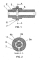
- FIGS 1 and 2 illustrate a bushing insulator of a medium voltage switchgear according to the invention.
- the bushing insulator comprises a body (1), which is made of an insulating material and provided with a primary current conductor (2) in the middle.
- the primary current conductor (2) is typically mounted in place before the part made of insulating material is moulded, and thus the primary current conductor is a fixed part of the bushing insulator.
- Coils (4) of a Rogowski sensor (3) are arranged inside a substantially enclosed screening cover (5) made of a metal, preferably zinc or zinc alloy.
- the screening cover (5) is supported in place during casting by a fitting part (6), whose one end is attached to an earthing connector (7).
- the fitting part (6) is dimensioned according to the insulator used so that the Rogowski sensor (3) will be around the primary current conductor in the middle of it.
- the fitting part (6) is made of an electrically conductive material, and thus no separate earthing connector is needed between the screening cover (5) and the earthing connector (7).
- the earthing connector (7) is arranged in the mould so that the Rogowski sensor stays firmly and accurately in place during casting.
- FIGs 3 and 4 illustrate a screening cover (5) which is formed of two halves (5a, 5b).
- the halves (5a, 5b) are preferably identical parts cast in the same mould, in which case it is easy to store and install them compared to the case where two different halves are used.
- the screening cover (5) is preferably made of zinc or zinc alloy, which is light, but another electrically conductive material, for example aluminium, may also be used.
- the outer surface of the screening cover (5) is annular and its cross section is substantially round.
- the screening cover comprises at least one ear (8), which preferably protrudes from the outer circumference and is provided with a cavity (9) for receiving the fitting part (6). Furthermore, the ear (8) is provided with a hole (10) for receiving an attachment member of the fitting part (6), such as a bolt and a nut or a rivet (not shown in the figure).
- the attachment member of the fitting part (6) such as a bolt and a nut or a rivet, is also arranged to attach the halves (5a, 5b) of the screening cover to each other and thus form an electrically conductive case which surrounds the coils (4) of the Rogowski sensor (3).
- the outer surface of the halves (5a, 5b) of the screening cover can be roughened e.g. by sandblasting so that epoxy resin sticks well to the outer surface and no separating surface is formed, which might cause undesired partial discharges due to the influence of the electric field.
- the inside of the annular wall of the screening cover is provided with support flanges (11) for accurate mounting of the cylindrical coils (4).
- the ends of the coil formers (4a) of the coils (4) made of insulating material rest on the support flanges (11) so that the coils are placed at equal distances in a plane perpendicular to the axial direction of the primary current conductors and form a polygon.
- the windings (4b) of the current measuring coils (4) are wound onto the coil former (4a) and the windings are electrically connected in series.
- the conductor at one end of the last coil of the series is arranged to be taken out of the screening cover (5) as a return conductor via the hubs of the hollow coil formers in the same manner as the first connecting wire of the Rogowski sensor via the hole (12) in the ear (8).
- the hole (12) is formed by semicircular cavities (13) provided in both halves (5a, 5b).
- Figure 5 illustrates overlap provided at the edges of the halves (5a, 5b) of the screening cover (5).
- the overlap is formed as follows: on the first side of the symmetry axis passing though the centre of the ear (8), the flange extends from the outer surface (14) on the inner and outer circumferences a distance corresponding to slightly less than half of the material thickness of the wall, and on the second side, the flange extends from the inner surface (15) on the inner and outer circumferences substantially the same distance corresponding to slightly less than half of the material thickness of the wall.
Landscapes
- Insulators (AREA)
- Transformers For Measuring Instruments (AREA)
- Measuring Instrument Details And Bridges, And Automatic Balancing Devices (AREA)
Abstract
Description
Claims (7)
- An insulator, such as a bushing insulator, which comprises a body (1) made of an insulating material, an opening for receiving a primary current conductor (2), a Rogowski sensor (3) arranged around the opening and a screening cover (5) which is made of a conductive material, receives winding or coils (4) of the Rogowski sensor and is arranged to form a loop with a closed cross section, characterized in that the screening cover (5) is provided with at least one ear (8) for receiving a fitting part (6), which is used to support the screening cover in place.
- An insulator according to claim 1, characterized in that the screening cover (5) is formed of two halves (5a, 5b).
- An insulator according to claim 2, characterized in that the halves (5a, 5b) of the screening cover (5) are moulded from zinc or zinc alloy.
- An insulator according to claim 3, characterized in that the screening cover (5) is in particular made of zinc alloy Zn Al 4 Cu 1.
- An insulator according to claims 2 to 4, characterized in that both halves (5a, 5b) of the screening cover have substantially the same shape.
- An insulator according to any one of claims 2 to 5, characterized in that the parts of the halves (5a, 5b) of the screening cover (5) that are against each other are arranged to overlap where relevant.
- An insulator according to any one of claims 1 to 6, characterized in that the fitting part (6) is made of a conductive material for earthing the screening cover (5).
Applications Claiming Priority (2)
| Application Number | Priority Date | Filing Date | Title |
|---|---|---|---|
| FI20021294A FI118142B (en) | 2002-06-28 | 2002-06-28 | Insulator |
| FI20021294 | 2002-06-28 |
Publications (3)
| Publication Number | Publication Date |
|---|---|
| EP1376621A2 true EP1376621A2 (en) | 2004-01-02 |
| EP1376621A3 EP1376621A3 (en) | 2004-01-28 |
| EP1376621B1 EP1376621B1 (en) | 2012-08-08 |
Family
ID=8564278
Family Applications (1)
| Application Number | Title | Priority Date | Filing Date |
|---|---|---|---|
| EP03396065A Expired - Lifetime EP1376621B1 (en) | 2002-06-28 | 2003-06-26 | Insulator |
Country Status (2)
| Country | Link |
|---|---|
| EP (1) | EP1376621B1 (en) |
| FI (1) | FI118142B (en) |
Cited By (1)
| Publication number | Priority date | Publication date | Assignee | Title |
|---|---|---|---|---|
| IT202200003494A1 (en) * | 2022-02-24 | 2023-08-24 | Boffetti S P A | ISOLATOR AND METHOD OF MANUFACTURING AN ISOLATOR |
Families Citing this family (2)
| Publication number | Priority date | Publication date | Assignee | Title |
|---|---|---|---|---|
| DE102015115264B3 (en) * | 2015-09-10 | 2016-08-18 | Semikron Elektronik Gmbh & Co. Kg | Centering device for a Rogowski coil, measuring device, power electronic device and a method for arranging a Rogowski coil |
| CN110609216B (en) * | 2019-11-03 | 2021-04-13 | 西南交通大学 | A method for locating faults of EMU cable terminals |
Family Cites Families (3)
| Publication number | Priority date | Publication date | Assignee | Title |
|---|---|---|---|---|
| FI965298A7 (en) * | 1996-12-31 | 1998-07-01 | Abb Transmit Oy | Insulator |
| FI974212A7 (en) * | 1997-11-12 | 1999-05-13 | Abb Transmit Oy | Insulator |
| FI109153B (en) * | 1998-01-30 | 2002-05-31 | Abb Technology Ltd | Piece of insulation blank with a continuous primary current line |
-
2002
- 2002-06-28 FI FI20021294A patent/FI118142B/en not_active IP Right Cessation
-
2003
- 2003-06-26 EP EP03396065A patent/EP1376621B1/en not_active Expired - Lifetime
Cited By (2)
| Publication number | Priority date | Publication date | Assignee | Title |
|---|---|---|---|---|
| IT202200003494A1 (en) * | 2022-02-24 | 2023-08-24 | Boffetti S P A | ISOLATOR AND METHOD OF MANUFACTURING AN ISOLATOR |
| EP4235705A1 (en) | 2022-02-24 | 2023-08-30 | Boffetti S.p.A. | Insulator and method for making an insulator |
Also Published As
| Publication number | Publication date |
|---|---|
| EP1376621A3 (en) | 2004-01-28 |
| FI118142B (en) | 2007-07-13 |
| FI20021294A7 (en) | 2003-12-29 |
| EP1376621B1 (en) | 2012-08-08 |
| FI20021294A0 (en) | 2002-06-28 |
Similar Documents
| Publication | Publication Date | Title |
|---|---|---|
| AU2005202036B2 (en) | Electric current measuring device, current sensor, electric trip unit and breaking device comprising such a measuring device | |
| JP3355579B2 (en) | Current and voltage converters for metal-filled gas-insulated high-voltage devices | |
| CN104813175B (en) | For the electric current and/or voltage sensing device of comprehensive purposes | |
| US7027280B2 (en) | Gas insulating apparatus and method for locating fault point thereof | |
| JP2001108711A (en) | Inductive pickup for measuring current in conductors | |
| EP2051084B1 (en) | Electrical quantity measuring device for energy transport lines | |
| EP1376621B1 (en) | Insulator | |
| US20240272203A1 (en) | Electrical current measurement module | |
| CN212303353U (en) | Adjustable inductor | |
| KR20210044462A (en) | Current measuring and gas insulated switchgear having the same | |
| FI109153B (en) | Piece of insulation blank with a continuous primary current line | |
| JPH1022149A (en) | Zero-phase current transformer | |
| JP4189164B2 (en) | Current measuring instrument | |
| US2892167A (en) | Tubular bar current transformer | |
| JP3929222B2 (en) | Instrument transformer | |
| RU2118008C1 (en) | Outdoor high-voltage current transformer | |
| US11617269B2 (en) | Current measuring device for an electric power protection system | |
| US20180211774A1 (en) | Method and Apparatus for Harvesting Electrical Energy from Current Carrying Elongate Conductors | |
| JP2002131341A (en) | Non-contact voltage sensor | |
| KR101035080B1 (en) | High precision power measurement sensor with Rogowski coil | |
| RU2765120C1 (en) | Current transformer module for distribution device and corresponding distribution device | |
| JPH0451465Y2 (en) | ||
| RU2046425C1 (en) | Current transformer with cast insulation | |
| PL66897Y1 (en) | Current high-voltage coil | |
| JPH0120756Y2 (en) |
Legal Events
| Date | Code | Title | Description |
|---|---|---|---|
| PUAI | Public reference made under article 153(3) epc to a published international application that has entered the european phase |
Free format text: ORIGINAL CODE: 0009012 |
|
| PUAL | Search report despatched |
Free format text: ORIGINAL CODE: 0009013 |
|
| AK | Designated contracting states |
Kind code of ref document: A2 Designated state(s): AT BE BG CH CY CZ DE DK EE ES FI FR GB GR HU IE IT LI LU MC NL PT RO SE SI SK TR |
|
| AX | Request for extension of the european patent |
Extension state: AL LT LV MK |
|
| AK | Designated contracting states |
Kind code of ref document: A3 Designated state(s): AT BE BG CH CY CZ DE DK EE ES FI FR GB GR HU IE IT LI LU MC NL PT RO SE SI SK TR |
|
| AX | Request for extension of the european patent |
Extension state: AL LT LV MK |
|
| 17P | Request for examination filed |
Effective date: 20040604 |
|
| AKX | Designation fees paid |
Designated state(s): AT BE BG CH CY CZ DE DK EE ES FI FR GB GR HU IE IT LI LU MC NL PT RO SE SI SK TR |
|
| GRAP | Despatch of communication of intention to grant a patent |
Free format text: ORIGINAL CODE: EPIDOSNIGR1 |
|
| GRAS | Grant fee paid |
Free format text: ORIGINAL CODE: EPIDOSNIGR3 |
|
| GRAA | (expected) grant |
Free format text: ORIGINAL CODE: 0009210 |
|
| AK | Designated contracting states |
Kind code of ref document: B1 Designated state(s): AT BE BG CH CY CZ DE DK EE ES FI FR GB GR HU IE IT LI LU MC NL PT RO SE SI SK TR |
|
| REG | Reference to a national code |
Ref country code: GB Ref legal event code: FG4D Ref country code: DE Ref legal event code: R081 Ref document number: 60341730 Country of ref document: DE Owner name: ABB SCHWEIZ AG, CH Free format text: FORMER OWNER: ABB RESEARCH LTD., ZUERICH, CH |
|
| REG | Reference to a national code |
Ref country code: CH Ref legal event code: EP Ref country code: AT Ref legal event code: REF Ref document number: 570137 Country of ref document: AT Kind code of ref document: T Effective date: 20120815 |
|
| REG | Reference to a national code |
Ref country code: IE Ref legal event code: FG4D |
|
| REG | Reference to a national code |
Ref country code: DE Ref legal event code: R096 Ref document number: 60341730 Country of ref document: DE Effective date: 20121011 |
|
| REG | Reference to a national code |
Ref country code: NL Ref legal event code: VDEP Effective date: 20120808 |
|
| REG | Reference to a national code |
Ref country code: AT Ref legal event code: MK05 Ref document number: 570137 Country of ref document: AT Kind code of ref document: T Effective date: 20120808 |
|
| PG25 | Lapsed in a contracting state [announced via postgrant information from national office to epo] |
Ref country code: AT Free format text: LAPSE BECAUSE OF FAILURE TO SUBMIT A TRANSLATION OF THE DESCRIPTION OR TO PAY THE FEE WITHIN THE PRESCRIBED TIME-LIMIT Effective date: 20120808 Ref country code: FI Free format text: LAPSE BECAUSE OF FAILURE TO SUBMIT A TRANSLATION OF THE DESCRIPTION OR TO PAY THE FEE WITHIN THE PRESCRIBED TIME-LIMIT Effective date: 20120808 Ref country code: CY Free format text: LAPSE BECAUSE OF FAILURE TO SUBMIT A TRANSLATION OF THE DESCRIPTION OR TO PAY THE FEE WITHIN THE PRESCRIBED TIME-LIMIT Effective date: 20120808 |
|
| PG25 | Lapsed in a contracting state [announced via postgrant information from national office to epo] |
Ref country code: SE Free format text: LAPSE BECAUSE OF FAILURE TO SUBMIT A TRANSLATION OF THE DESCRIPTION OR TO PAY THE FEE WITHIN THE PRESCRIBED TIME-LIMIT Effective date: 20120808 Ref country code: GR Free format text: LAPSE BECAUSE OF FAILURE TO SUBMIT A TRANSLATION OF THE DESCRIPTION OR TO PAY THE FEE WITHIN THE PRESCRIBED TIME-LIMIT Effective date: 20121109 Ref country code: PT Free format text: LAPSE BECAUSE OF FAILURE TO SUBMIT A TRANSLATION OF THE DESCRIPTION OR TO PAY THE FEE WITHIN THE PRESCRIBED TIME-LIMIT Effective date: 20121210 Ref country code: BE Free format text: LAPSE BECAUSE OF FAILURE TO SUBMIT A TRANSLATION OF THE DESCRIPTION OR TO PAY THE FEE WITHIN THE PRESCRIBED TIME-LIMIT Effective date: 20120808 Ref country code: SI Free format text: LAPSE BECAUSE OF FAILURE TO SUBMIT A TRANSLATION OF THE DESCRIPTION OR TO PAY THE FEE WITHIN THE PRESCRIBED TIME-LIMIT Effective date: 20120808 |
|
| PG25 | Lapsed in a contracting state [announced via postgrant information from national office to epo] |
Ref country code: NL Free format text: LAPSE BECAUSE OF FAILURE TO SUBMIT A TRANSLATION OF THE DESCRIPTION OR TO PAY THE FEE WITHIN THE PRESCRIBED TIME-LIMIT Effective date: 20120808 |
|
| PG25 | Lapsed in a contracting state [announced via postgrant information from national office to epo] |
Ref country code: DK Free format text: LAPSE BECAUSE OF FAILURE TO SUBMIT A TRANSLATION OF THE DESCRIPTION OR TO PAY THE FEE WITHIN THE PRESCRIBED TIME-LIMIT Effective date: 20120808 Ref country code: RO Free format text: LAPSE BECAUSE OF FAILURE TO SUBMIT A TRANSLATION OF THE DESCRIPTION OR TO PAY THE FEE WITHIN THE PRESCRIBED TIME-LIMIT Effective date: 20120808 Ref country code: EE Free format text: LAPSE BECAUSE OF FAILURE TO SUBMIT A TRANSLATION OF THE DESCRIPTION OR TO PAY THE FEE WITHIN THE PRESCRIBED TIME-LIMIT Effective date: 20120808 Ref country code: ES Free format text: LAPSE BECAUSE OF FAILURE TO SUBMIT A TRANSLATION OF THE DESCRIPTION OR TO PAY THE FEE WITHIN THE PRESCRIBED TIME-LIMIT Effective date: 20121119 |
|
| PG25 | Lapsed in a contracting state [announced via postgrant information from national office to epo] |
Ref country code: SK Free format text: LAPSE BECAUSE OF FAILURE TO SUBMIT A TRANSLATION OF THE DESCRIPTION OR TO PAY THE FEE WITHIN THE PRESCRIBED TIME-LIMIT Effective date: 20120808 |
|
| PLBE | No opposition filed within time limit |
Free format text: ORIGINAL CODE: 0009261 |
|
| STAA | Information on the status of an ep patent application or granted ep patent |
Free format text: STATUS: NO OPPOSITION FILED WITHIN TIME LIMIT |
|
| 26N | No opposition filed |
Effective date: 20130510 |
|
| PG25 | Lapsed in a contracting state [announced via postgrant information from national office to epo] |
Ref country code: BG Free format text: LAPSE BECAUSE OF FAILURE TO SUBMIT A TRANSLATION OF THE DESCRIPTION OR TO PAY THE FEE WITHIN THE PRESCRIBED TIME-LIMIT Effective date: 20121108 |
|
| REG | Reference to a national code |
Ref country code: DE Ref legal event code: R097 Ref document number: 60341730 Country of ref document: DE Effective date: 20130510 |
|
| PG25 | Lapsed in a contracting state [announced via postgrant information from national office to epo] |
Ref country code: MC Free format text: LAPSE BECAUSE OF FAILURE TO SUBMIT A TRANSLATION OF THE DESCRIPTION OR TO PAY THE FEE WITHIN THE PRESCRIBED TIME-LIMIT Effective date: 20120808 |
|
| REG | Reference to a national code |
Ref country code: CH Ref legal event code: PL |
|
| GBPC | Gb: european patent ceased through non-payment of renewal fee |
Effective date: 20130626 |
|
| REG | Reference to a national code |
Ref country code: IE Ref legal event code: MM4A |
|
| PG25 | Lapsed in a contracting state [announced via postgrant information from national office to epo] |
Ref country code: GB Free format text: LAPSE BECAUSE OF NON-PAYMENT OF DUE FEES Effective date: 20130626 Ref country code: LI Free format text: LAPSE BECAUSE OF NON-PAYMENT OF DUE FEES Effective date: 20130630 Ref country code: IE Free format text: LAPSE BECAUSE OF NON-PAYMENT OF DUE FEES Effective date: 20130626 Ref country code: CH Free format text: LAPSE BECAUSE OF NON-PAYMENT OF DUE FEES Effective date: 20130630 |
|
| PG25 | Lapsed in a contracting state [announced via postgrant information from national office to epo] |
Ref country code: TR Free format text: LAPSE BECAUSE OF FAILURE TO SUBMIT A TRANSLATION OF THE DESCRIPTION OR TO PAY THE FEE WITHIN THE PRESCRIBED TIME-LIMIT Effective date: 20120808 |
|
| PG25 | Lapsed in a contracting state [announced via postgrant information from national office to epo] |
Ref country code: HU Free format text: LAPSE BECAUSE OF FAILURE TO SUBMIT A TRANSLATION OF THE DESCRIPTION OR TO PAY THE FEE WITHIN THE PRESCRIBED TIME-LIMIT; INVALID AB INITIO Effective date: 20030626 Ref country code: LU Free format text: LAPSE BECAUSE OF NON-PAYMENT OF DUE FEES Effective date: 20130626 |
|
| REG | Reference to a national code |
Ref country code: FR Ref legal event code: PLFP Year of fee payment: 14 |
|
| REG | Reference to a national code |
Ref country code: DE Ref legal event code: R081 Ref document number: 60341730 Country of ref document: DE Owner name: ABB SCHWEIZ AG, CH Free format text: FORMER OWNER: ABB TECHNOLOGY AG, ZUERICH, CH |
|
| REG | Reference to a national code |
Ref country code: FR Ref legal event code: PLFP Year of fee payment: 15 |
|
| REG | Reference to a national code |
Ref country code: FR Ref legal event code: PLFP Year of fee payment: 16 |
|
| REG | Reference to a national code |
Ref country code: FR Ref legal event code: TP Owner name: ABB SCHWEIZ AG, CH Effective date: 20180912 |
|
| PGFP | Annual fee paid to national office [announced via postgrant information from national office to epo] |
Ref country code: CZ Payment date: 20190527 Year of fee payment: 17 |
|
| PGFP | Annual fee paid to national office [announced via postgrant information from national office to epo] |
Ref country code: FR Payment date: 20190628 Year of fee payment: 17 |
|
| PGFP | Annual fee paid to national office [announced via postgrant information from national office to epo] |
Ref country code: IT Payment date: 20190701 Year of fee payment: 17 Ref country code: DE Payment date: 20190628 Year of fee payment: 17 |
|
| REG | Reference to a national code |
Ref country code: DE Ref legal event code: R119 Ref document number: 60341730 Country of ref document: DE |
|
| PG25 | Lapsed in a contracting state [announced via postgrant information from national office to epo] |
Ref country code: CZ Free format text: LAPSE BECAUSE OF NON-PAYMENT OF DUE FEES Effective date: 20200626 |
|
| PG25 | Lapsed in a contracting state [announced via postgrant information from national office to epo] |
Ref country code: FR Free format text: LAPSE BECAUSE OF NON-PAYMENT OF DUE FEES Effective date: 20200630 |
|
| PG25 | Lapsed in a contracting state [announced via postgrant information from national office to epo] |
Ref country code: DE Free format text: LAPSE BECAUSE OF NON-PAYMENT OF DUE FEES Effective date: 20210101 |
|
| PG25 | Lapsed in a contracting state [announced via postgrant information from national office to epo] |
Ref country code: IT Free format text: LAPSE BECAUSE OF NON-PAYMENT OF DUE FEES Effective date: 20200626 |