EP1376327A2 - Touch panel device - Google Patents
Touch panel device Download PDFInfo
- Publication number
- EP1376327A2 EP1376327A2 EP03250422A EP03250422A EP1376327A2 EP 1376327 A2 EP1376327 A2 EP 1376327A2 EP 03250422 A EP03250422 A EP 03250422A EP 03250422 A EP03250422 A EP 03250422A EP 1376327 A2 EP1376327 A2 EP 1376327A2
- Authority
- EP
- European Patent Office
- Prior art keywords
- surface acoustic
- acoustic waves
- elements
- excitation
- receiving elements
- Prior art date
- Legal status (The legal status is an assumption and is not a legal conclusion. Google has not performed a legal analysis and makes no representation as to the accuracy of the status listed.)
- Granted
Links
Images


Classifications
-
- G—PHYSICS
- G06—COMPUTING; CALCULATING OR COUNTING
- G06F—ELECTRIC DIGITAL DATA PROCESSING
- G06F3/00—Input arrangements for transferring data to be processed into a form capable of being handled by the computer; Output arrangements for transferring data from processing unit to output unit, e.g. interface arrangements
- G06F3/01—Input arrangements or combined input and output arrangements for interaction between user and computer
- G06F3/03—Arrangements for converting the position or the displacement of a member into a coded form
- G06F3/041—Digitisers, e.g. for touch screens or touch pads, characterised by the transducing means
- G06F3/043—Digitisers, e.g. for touch screens or touch pads, characterised by the transducing means using propagating acoustic waves
- G06F3/0436—Digitisers, e.g. for touch screens or touch pads, characterised by the transducing means using propagating acoustic waves in which generating transducers and detecting transducers are attached to a single acoustic waves transmission substrate
Definitions
- the present invention relates to a touch panel device for detecting the presence of an object such as a finger or a pen, and more particularly relates to a touch panel device for detecting the position of the object by detecting attenuation and cutoff of surface acoustic waves (SAWs) by using excitation elements and receiving elements, each constructed by forming electrodes on a piezoelectric body.
- SAWs surface acoustic waves
- touch panel devices for detecting the contact position of an object such as a finger or a pen are a device using a resistance film, and a device using ultrasonic waves.
- a change in the resistance of the resistance film caused by contact of the object with the resistance film is detected.
- This device has the advantage of low consumption of power, but has problems in the aspects of response time, detection performance and durability.
- the contact position of the object is detected by propagating surface acoustic waves on a non-piezoelectric substrate, for example, and detecting attenuation of the surface acoustic waves caused by contact of the object such as a finger or a pen with the non-piezoelectric substrate.
- a touch panel device that uses, as transducers for exciting and receiving surface acoustic waves, comb-like electrodes (IDTs: inter digital transducers) capable of being produced collectively using a photolithography technique.
- each excitation element for exciting surface acoustic waves and each receiving element for receiving propagated surface acoustic waves an element constructed by forming a comb-like electrode on a piezoelectric body in the form of a thin film is used.
- FIG. 1 is an illustration showing the structure of such a conventional touch panel device using comb-like electrodes.
- the numeral 61 represents a rectangular non-piezoelectric substrate, and a plurality of excitation elements 62, each constructed by forming a comb-like electrode on a piezoelectric thin film, for exciting surface acoustic waves are arranged in a line on two adjacent sides (one in the X and one in the Y direction) of the non-piezoelectric substrate 61.
- a plurality of receiving elements 63 each constructed by forming a comb-like electrode on a piezoelectric thin film, for receiving surface acoustic waves are arranged in a line on the other two adjacent sides so that the receiving elements 63 face the excitation elements 62.
- periodic signals are inputted to the excitation elements 62 to excite surface acoustic waves and propagate them on the non-piezoelectric substrate 61, and then the propagated surface acoustic waves are received by the receiving elements 63.
- the surface acoustic waves attenuate. Accordingly, it is possible to detect the presence or absence of contact of the object and the contact position by detecting whether or not the level of the received signals at the receiving elements 63 is attenuated.
- the present inventor et al. have proposed a touch panel device in which the excitation elements and receiving elements are disposed so as to propagate surface acoustic waves in oblique directions (diagonal directions) of the non-piezoelectric substrate.
- This proposal is referred to below as a first prior art example, denoting in-house knowledge of the applicant.
- FIG. 2 is an illustration showing the structure of an example of such a touch panel device
- FIG. 3 is an enlarged sectional view of FIG. 2.
- the numeral 71 represents a rectangular non-piezoelectric substrate, and a center portion enclosed by an alternate long and short dashed line is a detection region 71a capable of detecting the contact position.
- excitation elements 72 are disposed on the upper side and lower side of the substrate 71, while receiving elements 73 are positioned on the left side and right side thereof.
- FIG. 4 is a partial cross sectional view of the excitation element 72 or the receiving element 73, and the excitation element 72 or the receiving element 73 is constructed by forming a comb-like electrode 75 on a piezoelectric body 74 in the form of a thin film.
- This comb-like electrode 75 comprises facing bus electrodes 77 and a plurality of electrode fingers 78 which are extended from the bus electrodes 77 and in some cases L-shaped.
- Such a structure in which electrode fingers 78 bend in the middle is also called a "chevron structure". According to this structure, lines of a plurality of electrode fingers 78 tilted in two directions from the facing direction of the bus electrodes 77 are formed, thereby realizing excitation of surface acoustic waves in two directions and reception of surface acoustic waves from two directions.
- Terminals 79 for input and ground are provided so that they are connected to the bus electrodes 77 of the upper-side and lower-side excitation elements 72. Moreover, terminals 79 for output and ground are provided so that they are connected to the bus electrodes 77 of the left-side and right-side receiving elements 73. Further, peripheral wires 80 are connected to the terminals 79, respectively.
- the present inventor et al. have proposed a touch panel device comprising a film-like piezoelectric body, a comb-like electrode formed on one surface of the piezoelectric body, and a plate electrode formed on the other surface of the piezoelectric body (hereinafter referred to as the "second prior art example" in the sense of in-house prior art).
- Each of the excitation element and receiving element is constructed by forming a comb-like electrode produced by extending a plurality of electrode fingers which are bent part way along and have the same polarity on one surface of the piezoelectric body, instead of a comb-like electrode in which electrode fingers of different polarities are placed alternately, and by forming a plate electrode with a polarity different from the comb-like electrode on the other surface of the piezoelectric body.
- the second prior art example requires only a width of one line of a bus electrode, thereby making it possible to narrow the frame region.
- This electrode structure of the second prior art example is also called an "SPT (Single Phased Transducer) electrode structure".
- the propagation distance of the surface acoustic waves is not uniform. Since the surface acoustic waves are attenuated by the propagation, a high-level received signal is obtained by the receiving element in a region with a short propagation distance between the excitation element and the receiving element. However, in a region with long propagation distance between the excitation element and the receiving element (region near the diagonal of the substrate), the surface acoustic wave is attenuated considerably and there is a problem that a high-level received signal is not obtained by the receiving element. As a result, the signal/noise (S/N) ratio in the region near the diagonal decreases and high detection accuracy is not obtained for the detections of presence or absence of contact of an object and the contact position, and thus there is room for improvement.
- S/N signal/noise
- a touch panel device comprises excitation elements for exciting surface acoustic waves and receiving elements for receiving surface acoustic waves, disposed at peripheral sections in diagonal directions of a rectangular substrate to form pairs, and propagates surface acoustic waves between the excitation elements and the receiving elements in diagonal directions on the substrate so as to detect the position of an object in contact with the substrate.
- the excitation elements and the receiving elements have comb-like electrode fingers, and the widths of the comb-like electrode fingers of the excitation elements and/or the receiving elements are set according to the lengths of propagation distances of the surface acoustic waves.
- the widths of the comb-like electrode fingers are varied according to the propagation distances of the surface acoustic waves, i.e., the widths of the comb-like electrode fingers are increased in a region with long surface acoustic propagation distance (region near the diagonal) so as to achieve maximum excitation efficiency, while the widths of the comb-like electrode fingers are decreased in a region with short surface acoustic propagation distance (region near the corner). Consequently, a high S/N ratio is ensured in the region with long propagation distance (region near the diagonal) where the influence of propagation loss of the surface acoustic waves becomes larger.
- the excitation elements and the receiving elements have comb-like electrode fingers, and the number of pairs of the comb-like electrode fingers of the excitation elements and/or the receiving elements is set according to the lengths of propagation distances of the surface acoustic waves.
- the number of pairs of the electrode fingers is varied according to the propagation distances of the surface acoustic waves, i.e., the number of pairs of the electrode fingers is increased in a region with long surface acoustic wave propagation distance (region near the diagonal), while the number of pairs of the electrode fingers is decreased in a region with short surface acoustic wave propagation distance.
- the S/N ratio is determined by the sensitivity proportional to the number of pairs, a high S/N ratio is ensured in the region with long propagation distance (region near the diagonal) where the influence of propagation loss of the surface acoustic waves becomes larger.
- each of the excitation elements and the receiving elements comprises a comb-like electrode having a plurality of electrode fingers
- the aperture width of the comb-like electrode of the excitation elements and/or the receiving elements is set according to the lengths of propagation distances of the surface acoustic waves.
- the aperture width of the comb-like electrode is varied according to the propagation distances of the surface acoustic waves, i.e., the aperture width of the comb-like electrode is increased in a region with long surface acoustic wave propagation distance, while the aperture width of the comb-like electrodes is decreased in a region with short propagation distance.
- the S/N ratio is determined by the sensitivity proportional to the aperture width, a high S/N ratio is ensured in the region with long propagation distance (region near the diagonal) where the influence of propagation loss of the surface acoustic waves becomes larger.
- the excitation elements and the receiving elements have a plurality of terminals at different positions for connection to an external device, and the terminal at a position (on a side) where the propagation distance of the surface acoustic waves is longer is selectively used.
- an excitation signal is inputted or a received signal is outputted through the terminal provided in a region with long surface acoustic wave propagation distance (region near the diagonal).
- a touch panel device of a fifth aspect further comprises additional excitation elements for exciting surface acoustic waves and additional receiving elements for receiving surface acoustic waves, disposed at four corners of the substrate to form pairs.
- excitation elements for exciting surface acoustic waves and receiving elements for receiving surface acoustic waves are further provided to form pairs in the diagonal directions. Therefore, since the signal strength in the region with long propagation distance where the influence of the propagation loss of the surface acoustic wave becomes larger (region near the diagonal) is increased, a high S/N ratio is ensured in the region with long propagation distance (region near the diagonal).
- a touch panel device of a sixth aspect is based on any combination of the first through fifth aspects, wherein each of the excitation elements and the receiving elements comprises a film-like piezoelectric body, a comb-like electrode formed on one surface of the piezoelectric body, and a plate electrode formed on the other surface of the piezoelectric body.
- each of the excitation elements and receiving elements is constructed by forming a comb-like electrode composed of a plurality of electrode fingers having the same polarity on one surface of the piezoelectric body and forming a plate electrode with a polarity different from the comb-like electrode on the other surface of the piezoelectric body. It is therefore possible to narrow the frame region, improve the degree of freedom in design of the electrodes, and easily ensure a high S/N ratio in the region with long propagation distance (region near the diagonal) in any of the first to fifth aspects.
- the touch panel device of the present invention may be applied to a display device ("touch screen”) or to an input device (e.g. graphics tablet).
- a display device touch screen
- an input device e.g. graphics tablet
- FIG. 5 is an illustration showing the structure of the touch panel device of the second prior art example having an SPT electrode structure to which the present invention is applied
- FIG. 6 is an enlarged sectional view of FIG. 5.
- the numeral 1 represents a rectangular non-piezoelectric substrate which is made of a glass material, for example, and capable of propagating surface acoustic waves, and a center portion enclosed by an alternate long and short dash line is a detection region 1a capable of detecting a contact position.
- Excitation elements 2 for exciting surface acoustic waves in two directions are provided on the upper side and lower side of a frame region 1b outside the detection region 1a, which is a peripheral section of the non-piezoelectric substrate 1, and receiving elements 3 for receiving surface acoustic waves from two directions are provided on the left side and the right side thereof.
- FIG. 7 is a partial cross sectional view of the excitation element 2 or receiving element 3.
- the excitation element 2 or receiving element 3 is constructed by forming a comb-like electrode 5 on one surface (front surface) of a piezoelectric body 4 in the form of a thin film made of A1N or ZnO, for example, and forming a plate electrode (solid electrode) 6 on the other surface (rear surface) thereof.
- the comb-like electrode 5 on the front surface comprises one line of bus electrode 7, and a plurality of electrode fingers 8 which are connected to the bus electrode 7 and some of which are V shaped.
- the plate electrode 6 is shown by a broken line, and the installation range of the piezoelectric body 4 is indicated by an alternate long and short dash line.
- Such a comb-like electrode 5 and plate electrode 6 are connected to external circuits (an oscillation circuit, receiving level detection circuit, etc.).
- Terminals 9 for input are provided and connected to the comb-like electrodes 5 (via bus electrodes 7) of the upper-side and lower-side excitation elements 2, and terminals 9 for ground are provided and connected to the plate electrodes 6 of these excitation elements 2.
- terminals 9 for output are provided and connected to the comb-like electrodes 5 (bus electrodes 7) of the left-side and right-side receiving elements 3, and terminals 9 for ground are provided and connected to the plate electrodes 6 of these receiving elements 3.
- drawn-round (peripheral) wires 10 are connected to the respective terminals 9.
- the surface acoustic waves from the upper-side excitation element 2 are propagated in a lower-left oblique direction and a lower-right oblique direction and then received by the left-side and right-side receiving elements 3, while the surface acoustic waves from the lower-side excitation element 2 are propagated in an upper-left oblique direction and an upper-right oblique direction and then received by the left-side and right-side receiving elements 3.
- each of the excitation elements 2 and the receiving elements 3 are constructed by forming the comb-like electrode 5 composed of a plurality of electrode fingers 8 of the same polarity on the front surface of the piezoelectric body 4 and forming the plate electrode 6 with a polarity different from the electrode fingers 8 on the rear surface of the piezoelectric body 4 (see FIG. 7). Therefore, compared to the first prior art example that requires a width of two lines of bus electrodes 77 on each side due to the presence of electrodes of different polarities on the same plane, only a width of one line of bus electrode 7 is necessary, and consequently the frame region 1b can be narrowed. Moreover, since there is no need to dispose electrodes of different polarities on the same plane, design freedom is increased.
- the width of the electrode finger 78 is 1/4 of the wavelength of the surface acoustic wave.
- the width of the electrode finger 8 need be only 1/2 of the wavelength of the surface acoustic wave. It is therefore possible to relax the requirement for the fineness of patterning when manufacturing the electrodes, and more easily manufacture the electrode fingers compared to the first prior art example. As a result, it becomes possible to manufacture the electrodes at low costs using methods such as a liftoff method and a conductive material screen printing method.
- FIG. 8 is a graph showing the excitation efficiency in the touch panel device having the SPT electrode structure, wherein the abscissa indicates a ratio w/ ⁇ , of the width (w) of the electrode finger 8 to the pitch ( ⁇ ) of the electrode fingers 8, while the ordinate indicates excitation efficiency ⁇ .
- the maximum excitation efficiency is exhibited when w/ ⁇ , takes a value near 0.4 to 0.5.
- the comb-like electrodes 5 of the excitation elements 2 and receiving elements 3 are designed so that excitation efficiency corresponding to the need is added to each of the channels having different surface acoustic wave propagation distances.
- the pitch of the electrode fingers 8 can not be changed because a change thereof causes variations in the frequency of the surface acoustic waves. Therefore, the width of each electrode finger 8 is variably set.
- FIG. 9 is an illustration showing the electrode structure of a part of the touch panel device of the first embodiment.
- the widths of the electrode fingers 8 extending from the bus electrodes 7 of the comb-like electrodes 5 of the excitation element 2 and receiving element 3 are made wider sequentially. Further, the width of each electrode finger 8 is set so that maximum excitation efficiency is obtained in a region near the diagonal where the propagation distance is longest. Accordingly, it becomes possible to realize a high S/N ratio even in a region near the diagonal where large propagation loss is caused.
- the sensitivity in the region near the diagonal is improved by varying the number of pairs of the electrode fingers 8 and/or the aperture width of the comb-like electrode 5, according to the propagation distances of the surface acoustic waves.
- FIG. 10 is an illustration showing the electrode structure of a part of a touch panel device of the first example of the second embodiment. It is clear from a comparison with FIG. 6 that, as the surface acoustic wave propagation distance increases, the number of pairs of the electrode fingers 8 extending from the bus electrodes 7 of the comb-like electrodes 5 of the excitation element 2 and receiving element 3 is gradually increased and the aperture width of the comb-like electrode 5 is gradually increased. Moreover, in a region (a corner of the panel) with particularly short surface acoustic wave propagation distance, the number of pairs of the electrode fingers 8 is decreased and the aperture width of the comb-like electrode 5 is narrowed.
- FIG. 11 is an illustration showing the electrode structure of a part of a touch panel device of the second example of the second embodiment. It is clear from a comparison with FIG. 6 that, in a region with the longest surface acoustic wave propagation distance between the excitation element 2 and the receiving element 3, by extending the electrode fingers 8 to the outside, the number of pairs of the electrode fingers 8 is increased without changing the aperture width of the comb-like electrode 5.
- FIG. 12 is an illustration showing the electrode structure of a part of a touch panel device of the third example of the second embodiment. It is clear from a comparison with FIG. 6 that, in the region with the longest surface acoustic wave propagation distance between the excitation element 2 and the receiving element 3, by extending the electrode fingers 8 to the inside, the number of pairs of the electrode fingers 8 is increased without changing the aperture width of the comb-like electrode 5.
- FIG. 13 is an illustration showing the electrode structure of a part of a touch panel device of the fourth example of the second embodiment.
- the fourth example is an example in which the electrode fingers 8 are extended to the outside like the second example, but the extended amount is small compared to the second example. In order to increase the sensitivity by only a necessary amount, the extended portion of the electrode fingers 8 is provided in only a range sufficient for the need.
- the extended portion of the electrode fingers 8 is provided so as to improve the sensitivity in a region with long propagation distance (region near the diagonal).
- the extended portion is provided on the transmission side (excitation element 2)
- the receiving efficiency is determined by the structure, but, on the transmission side (excitation element 2), the excitation efficiency can be increased by improving oscillation such as excitation of burst waves.
- the extended portion of the electrode fingers 8 is provided on the transmission side (excitation element 2), there is a possibility of receiving large influence of diffraction, and therefore care must be taken. Accordingly, when increasing the sensitivity to a small degree, it is preferable to provide the extended portion of the electrode fingers 8 only on the receiving side (receiving element 3).
- FIG. 14 is a schematic view of a touch panel device of the first example of the third embodiment.
- one extended portion 20 of the electrode fingers 8 is provided inside the comb-like electrode 5 by effectively using empty space. More specifically, in a region where surface acoustic waves are propagated from the upper-side excitation element 2 to the right-side receiving element 3, the extended portion 20 is provided inside the comb-like electrode 5 of the upper-side excitation element 2. In a region where surface acoustic waves are propagated from the upper-side excitation element 2 to the left-side receiving element 3, the extended portion 20 is provided inside the comb-like electrode 5 of the left-side receiving element 3.
- the extended portion 20 is provided inside the comb-like electrode 5 of the right-side receiving element 3. In a region where surface acoustic waves are propagated from the lower-side excitation element 2 to the left-side receiving element 3, the extended portion 20 is provided inside the comb-like electrode 5 of the lower-side excitation element 2.
- FIG. 15 is a schematic view of a touch panel device of the second example of the third embodiment.
- two extended portions 20 of the electrode fingers 8 are provided outside the original comb-like electrode 5. More specifically, in a region where surface acoustic waves are propagated from the upper-side excitation element 2 and the lower-side excitation element 2 to the right-side receiving element 3, two extended portions 20 are provided outside the regular comb 5 of the right-side receiving element 3. In a region where surface acoustic waves are propagated from the upper-side excitation element 2 and the lower-side excitation element 2 to the left-side receiving element 3, two extended portions 20 are provided outside the original comb-like electrode 5 of the left-side receiving element 3.
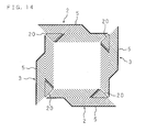
- FIG. 16 is a schematic view of a touch panel device of the third example of the third embodiment.
- two extended portions 20 of the electrode fingers 8 are provided inside and outside the original comb-like electrode 5 respectively. More specifically, in a region where surface acoustic waves are propagated from the upper-side excitation element 2 to the right-side receiving element 3, an extended portion 20 is provided inside the comb-like electrode 5 of the upper-side excitation element 2. In a region where surface acoustic waves are propagated from the upper-side excitation element 2 to the left-side receiving element 3, an extended portion 20 is provided outside the comb-like electrode 5 of the upper-side excitation element 2.
- an extended portion 20 is provided outside the comb-like electrode 5 of the lower-side excitation element 2.
- an extended portion 20 is provided inside the comb-like electrode 5 of the lower-side excitation element 2.
- the extended portion 20 of the electrode fingers 8 is provided inside the original comb-like electrode 5, since the extended portion 20 does not protrude outside, it is not necessary to widen the frame region 1b
- the extended portion 20 of the electrode fingers 8 is provided outside the comb-like electrode 5, unlike the case of providing the extended portion 20 inside the comb-like electrode 5, the time difference can be maintained, and the addition effect during excitation and the received signal at the receiving end have no distortion, thereby eliminating the necessity for a special process.
- a decision can be made as to whether the extended portions 20 of the electrode fingers 8 are provided inside or outside the regular comb 5.
- the layouts of the extended portions 20 of the electrode fingers 8 of the first to third examples are examples, and, needless to say, it is possible to adopt other layout examples such as a layout in which one extended portion 20 is provided for each of the excitation elements 2 and receiving elements 3 so that the extended portions 20 protrude to the outside.
- FIG. 17 and FIG. 18 are illustrations showing the electrode structure of a part (the left-side receiving element 3) of a touch panel device of the fourth embodiment, wherein FIG. 17 represents an example in which no extended portion of the electrode fingers 8 is provided, and FIG. 18 represents an example having an extended portion (like extended portion 20 in FIGS 14-16).
- 9a, 9b and 9c are terminals provided at different positions on the plate electrode 6.
- the terminal of the plate electrode 6 is the upper-side terminal 9a
- the transmission distance of the received signal on the plate electrode 6 is short and the transmission loss is small
- the transmission distance of the received signal on the plate electrode 6 is long and the transmission loss is large.
- the terminal of the plate electrode 6 is the lower-side terminal 9c
- the transmission distance of the received signal on the plate electrode 6 is long and the transmission loss is large
- the transmission distance of the received signal on the plate electrode 6 is short and the transmission loss is small.
- FIG. 19 and FIG. 20 show the characteristics of FIG. 17 and FIG. 18, respectively.
- the abscissa indicates a time (proportional to the surface acoustic wave propagation distance)
- the ordinate indicates the strength of the received signal
- the solid line a, broken line b and alternate long and short dash line c represent the characteristics obtained by selecting the terminals 9a, 9b and 9c, respectively.
- an improvement in the strength of the received signal in a region near the diagonal where the propagation distance is longest is recognized at the end of reception by the effect of the extended portion (see FIG. 20).
- the terminal 9c When the terminal 9c is selected, in the region near the diagonal where the propagation distance is longest, large transmission loss on the plate electrode 6 is added to large propagation loss, and the strength of the received signal becomes extremely low.
- the terminal 9a when the terminal 9a is selected, in the region near the diagonal where the propagation distance is longest, although the propagation loss is large, the strength of the received signal is high because there is almost no transmission loss on the plate electrode 6.
- the terminal 9a in order to improve the sensitivity in the region near the diagonal where the propagation distance is longest when receiving the surface acoustic waves from the lower-side excitation element 2, it is preferable to select the terminal 9a.
- the terminal 9c when receiving the surface acoustic waves from the upper-side excitation element 2, since the relationship is completely opposite to that for receiving the surface acoustic waves from the lower-side excitation element 2, it is preferable to select the terminal 9c to improve the sensitivity in the region near the diagonal where the propagation distance is longest.
- FIG. 21 is an illustration showing the electrode structure of a part of a touch panel device of the fifth embodiment
- FIG. 22 is a schematic illustration of the same touch panel device.
- excitation elements 2a for exciting surface acoustic waves and receiving elements 3a for receiving surface acoustic waves are additionally provided, independently of the existing excitation elements 2 and receiving elements 3, at the four corners of the frame region to form pairs in the diagonal directions.
- the excitation elements 2a for exciting surface acoustic waves in a lower-right oblique direction and a lower-left oblique direction are provided at the upper left corner and the upper right corner, respectively
- the receiving elements 3a for receiving surface acoustic waves propagated from an upper-right oblique direction and an upper-left oblique direction are provided at the lower left corner and the lower right corner, respectively.
- these additional excitation elements 2a and receiving elements 3a may be driven completely independently of the excitation elements 2 and the receiving elements 3, or driven in an interlocked manner with the excitation elements 2 and the receiving elements 3.
- interlock driving in order to maintain the continuity of signals, it is necessary to make the aperture width of the comb-like electrodes of the excitation elements 2a and receiving elements 3a smaller than the diameter of a pen tip for pointing at a position.
- the additional excitation elements 2a and receiving elements 3a can overlap the existing excitation elements 2 and receiving elements 3. In this case, the detection accuracy can be improved by performing switching according to the need.
- touch panel device having the SPT electrode structure (the second prior art example) is used as the basis, it is, of course, possible to similarly apply the present invention to all touch panel devices which are constructed to propagate surface acoustic waves in the diagonal directions of the substrate, including a touch panel device (the first prior art example) as shown in FIG. 2.
- the widths of the electrode fingers of the excitation elements and/or the receiving elements are increased according to an increase in the surface acoustic wave propagation distance, it is possible to realize a high S/N ratio in a region with long surface acoustic wave propagation distance (region near the diagonal).
- the touch panel device of the second and third embodiments since the number of pairs of the electrode fingers of the excitation elements and/or the receiving elements is increased and/or the aperture width of the comb-like electrode of the excitation elements and/or the receiving elements is increased according to an increase in the surface acoustic wave propagation distance, it is possible to realize a high S/N ratio in the region with long surface acoustic wave propagation distance (region near the diagonal).
- the touch panel device since the touch panel device according to the sixth aspect is designed to have an SPT electrode structure in which the comb-like electrode is formed on one surface of the piezoelectric body and the plate electrode is formed on the other surface thereof, it is possible to narrow the frame region, improve the degree of freedom in design of the electrodes, and easily ensure a high S/N ratio in the region with long surface acoustic wave propagation distance (region near the diagonal).
- the touch panel device of the present invention since a high sensitivity can be realized even in a region with long surface acoustic wave propagation distance (region near the diagonal), it is possible to improve the accuracy of detecting the presence or absence of contact of an object and the contact position.
- references in this specification to contact between an object and a substrate include any intervention by the object capable of attenuating the propagation of SAWs, and are not restricted to direct physical touching of the substrate.
Abstract
Description
- The present invention relates to a touch panel device for detecting the presence of an object such as a finger or a pen, and more particularly relates to a touch panel device for detecting the position of the object by detecting attenuation and cutoff of surface acoustic waves (SAWs) by using excitation elements and receiving elements, each constructed by forming electrodes on a piezoelectric body.
- With the spread of computer systems, mainly personal computers, there has been used a device for inputting new information or giving various instructions to a computer system by pointing at a position on a display screen of a display device on which information is displayed by the computer system, with an object such as a finger or a pen. In order to perform an input operation with respect to the information displayed on the display screen of the display device of a personal computer or the like by a touching method, it is necessary to detect the contact position (indicated position) on the display screen with high accuracy.
- Well known examples of touch panel devices for detecting the contact position of an object such as a finger or a pen are a device using a resistance film, and a device using ultrasonic waves. In the former device using a resistance film, a change in the resistance of the resistance film caused by contact of the object with the resistance film is detected. This device has the advantage of low consumption of power, but has problems in the aspects of response time, detection performance and durability.
- By contrast, in the device using ultrasonic waves, the contact position of the object is detected by propagating surface acoustic waves on a non-piezoelectric substrate, for example, and detecting attenuation of the surface acoustic waves caused by contact of the object such as a finger or a pen with the non-piezoelectric substrate. There has been developed a touch panel device that uses, as transducers for exciting and receiving surface acoustic waves, comb-like electrodes (IDTs: inter digital transducers) capable of being produced collectively using a photolithography technique. In this touch panel device, as each excitation element for exciting surface acoustic waves and each receiving element for receiving propagated surface acoustic waves, an element constructed by forming a comb-like electrode on a piezoelectric body in the form of a thin film is used.
- FIG. 1 is an illustration showing the structure of such a conventional touch panel device using comb-like electrodes. In FIG. 1, the
numeral 61 represents a rectangular non-piezoelectric substrate, and a plurality ofexcitation elements 62, each constructed by forming a comb-like electrode on a piezoelectric thin film, for exciting surface acoustic waves are arranged in a line on two adjacent sides (one in the X and one in the Y direction) of thenon-piezoelectric substrate 61. Moreover, a plurality of receivingelements 63, each constructed by forming a comb-like electrode on a piezoelectric thin film, for receiving surface acoustic waves are arranged in a line on the other two adjacent sides so that thereceiving elements 63 face theexcitation elements 62. - In this touch panel device, periodic signals are inputted to the
excitation elements 62 to excite surface acoustic waves and propagate them on thenon-piezoelectric substrate 61, and then the propagated surface acoustic waves are received by thereceiving elements 63. Moreover, when an object such as a finger or a pen comes into contact with the propagation path of the surface acoustic waves on thenon-piezoelectric substrate 61, the surface acoustic waves attenuate. Accordingly, it is possible to detect the presence or absence of contact of the object and the contact position by detecting whether or not the level of the received signals at thereceiving elements 63 is attenuated. - Furthermore, in order to achieve continuous detection of the presence or absence of contact of an object and the contact position and increase the time difference to improve the resolution of the detected position, the present inventor et al. have proposed a touch panel device in which the excitation elements and receiving elements are disposed so as to propagate surface acoustic waves in oblique directions (diagonal directions) of the non-piezoelectric substrate. This proposal is referred to below as a first prior art example, denoting in-house knowledge of the applicant.
- FIG. 2 is an illustration showing the structure of an example of such a touch panel device, and FIG. 3 is an enlarged sectional view of FIG. 2. In FIG. 2, the
numeral 71 represents a rectangular non-piezoelectric substrate, and a center portion enclosed by an alternate long and short dashed line is a detection region 71a capable of detecting the contact position. - In a
frame region 71b outside the detection region 71a, which is a peripheral section of thenon-piezoelectric substrate 71,excitation elements 72 are disposed on the upper side and lower side of thesubstrate 71, while receivingelements 73 are positioned on the left side and right side thereof. FIG. 4 is a partial cross sectional view of theexcitation element 72 or thereceiving element 73, and theexcitation element 72 or thereceiving element 73 is constructed by forming a comb-like electrode 75 on apiezoelectric body 74 in the form of a thin film. This comb-like electrode 75 comprises facingbus electrodes 77 and a plurality ofelectrode fingers 78 which are extended from thebus electrodes 77 and in some cases L-shaped. Such a structure in whichelectrode fingers 78 bend in the middle is also called a "chevron structure". According to this structure, lines of a plurality ofelectrode fingers 78 tilted in two directions from the facing direction of thebus electrodes 77 are formed, thereby realizing excitation of surface acoustic waves in two directions and reception of surface acoustic waves from two directions. -
Terminals 79 for input and ground are provided so that they are connected to thebus electrodes 77 of the upper-side and lower-side excitation elements 72. Moreover,terminals 79 for output and ground are provided so that they are connected to thebus electrodes 77 of the left-side and right-side receiving elements 73. Further,peripheral wires 80 are connected to theterminals 79, respectively. - In such a structure, surface acoustic waves are excited in two directions by the
excitation elements 72, and the excited surface acoustic waves are propagated in two diagonal directions of thenon-piezoelectric substrate 71 and then received by thereceiving elements 73. Based on the received results, the presence or absence of contact of an object and the contact position are detected in the same manner as in the conventional example shown in FIG. 1. - Furthermore, the present inventor et al. have proposed a touch panel device comprising a film-like piezoelectric body, a comb-like electrode formed on one surface of the piezoelectric body, and a plate electrode formed on the other surface of the piezoelectric body (hereinafter referred to as the "second prior art example" in the sense of in-house prior art). Each of the excitation element and receiving element is constructed by forming a comb-like electrode produced by extending a plurality of electrode fingers which are bent part way along and have the same polarity on one surface of the piezoelectric body, instead of a comb-like electrode in which electrode fingers of different polarities are placed alternately, and by forming a plate electrode with a polarity different from the comb-like electrode on the other surface of the piezoelectric body. Compared to the first prior art example which requires a width of two lines of bus electrodes on each side due to the presence of the electrodes of different polarities on the same plane, the second prior art example requires only a width of one line of a bus electrode, thereby making it possible to narrow the frame region. In addition, since there is no need to provide electrodes of different polarities on the same plane, it is possible to improve the degree of freedom in design of the peripheral wires, etc. This electrode structure of the second prior art example is also called an "SPT (Single Phased Transducer) electrode structure".
- In the first and second prior art examples of propagating surface acoustic waves in diagonal directions, the propagation distance of the surface acoustic waves is not uniform. Since the surface acoustic waves are attenuated by the propagation, a high-level received signal is obtained by the receiving element in a region with a short propagation distance between the excitation element and the receiving element. However, in a region with long propagation distance between the excitation element and the receiving element (region near the diagonal of the substrate), the surface acoustic wave is attenuated considerably and there is a problem that a high-level received signal is not obtained by the receiving element. As a result, the signal/noise (S/N) ratio in the region near the diagonal decreases and high detection accuracy is not obtained for the detections of presence or absence of contact of an object and the contact position, and thus there is room for improvement.
- It is therefore desirable to provide a touch panel device capable of improving the S/N ratio in a region near the diagonal where the influence of propagation loss of the surface acoustic waves is large, and improving the accuracy of detecting the presence or absence of contact of an object and the contact position.
- A touch panel device according to the present invention comprises excitation elements for exciting surface acoustic waves and receiving elements for receiving surface acoustic waves, disposed at peripheral sections in diagonal directions of a rectangular substrate to form pairs, and propagates surface acoustic waves between the excitation elements and the receiving elements in diagonal directions on the substrate so as to detect the position of an object in contact with the substrate.
- In a touch panel device of a first aspect, the excitation elements and the receiving elements have comb-like electrode fingers, and the widths of the comb-like electrode fingers of the excitation elements and/or the receiving elements are set according to the lengths of propagation distances of the surface acoustic waves. In the touch panel device of the first aspect, the widths of the comb-like electrode fingers are varied according to the propagation distances of the surface acoustic waves, i.e., the widths of the comb-like electrode fingers are increased in a region with long surface acoustic propagation distance (region near the diagonal) so as to achieve maximum excitation efficiency, while the widths of the comb-like electrode fingers are decreased in a region with short surface acoustic propagation distance (region near the corner). Consequently, a high S/N ratio is ensured in the region with long propagation distance (region near the diagonal) where the influence of propagation loss of the surface acoustic waves becomes larger.
- In a touch panel device of a second aspect, the excitation elements and the receiving elements have comb-like electrode fingers, and the number of pairs of the comb-like electrode fingers of the excitation elements and/or the receiving elements is set according to the lengths of propagation distances of the surface acoustic waves. In the touch panel device of the second aspect, the number of pairs of the electrode fingers is varied according to the propagation distances of the surface acoustic waves, i.e., the number of pairs of the electrode fingers is increased in a region with long surface acoustic wave propagation distance (region near the diagonal), while the number of pairs of the electrode fingers is decreased in a region with short surface acoustic wave propagation distance. Therefore, since the S/N ratio is determined by the sensitivity proportional to the number of pairs, a high S/N ratio is ensured in the region with long propagation distance (region near the diagonal) where the influence of propagation loss of the surface acoustic waves becomes larger.
- In a touch panel device of a third aspect, each of the excitation elements and the receiving elements comprises a comb-like electrode having a plurality of electrode fingers, and the aperture width of the comb-like electrode of the excitation elements and/or the receiving elements is set according to the lengths of propagation distances of the surface acoustic waves. In the touch panel device of the third aspect, the aperture width of the comb-like electrode is varied according to the propagation distances of the surface acoustic waves, i.e., the aperture width of the comb-like electrode is increased in a region with long surface acoustic wave propagation distance, while the aperture width of the comb-like electrodes is decreased in a region with short propagation distance. Therefore, since the S/N ratio is determined by the sensitivity proportional to the aperture width, a high S/N ratio is ensured in the region with long propagation distance (region near the diagonal) where the influence of propagation loss of the surface acoustic waves becomes larger.
- In a touch panel device of a fourth aspect, the excitation elements and the receiving elements have a plurality of terminals at different positions for connection to an external device, and the terminal at a position (on a side) where the propagation distance of the surface acoustic waves is longer is selectively used. In the touch panel device of the fourth aspect, an excitation signal is inputted or a received signal is outputted through the terminal provided in a region with long surface acoustic wave propagation distance (region near the diagonal). Therefore, since the transmission loss due to the electrode resistance in the region with long propagation distance where the influence of the propagation loss of the surface acoustic wave becomes larger (region near the diagonal) is reduced compared to other regions, a high S/N ratio is ensured in the region with long propagation distance (region near the diagonal).
- A touch panel device of a fifth aspect further comprises additional excitation elements for exciting surface acoustic waves and additional receiving elements for receiving surface acoustic waves, disposed at four corners of the substrate to form pairs. In the touch panel device of the fifth aspect, at the four corners of the substrate, excitation elements for exciting surface acoustic waves and receiving elements for receiving surface acoustic waves are further provided to form pairs in the diagonal directions. Therefore, since the signal strength in the region with long propagation distance where the influence of the propagation loss of the surface acoustic wave becomes larger (region near the diagonal) is increased, a high S/N ratio is ensured in the region with long propagation distance (region near the diagonal).
- A touch panel device of a sixth aspect is based on any combination of the first through fifth aspects, wherein each of the excitation elements and the receiving elements comprises a film-like piezoelectric body, a comb-like electrode formed on one surface of the piezoelectric body, and a plate electrode formed on the other surface of the piezoelectric body. In the touch panel device of the sixth aspect, each of the excitation elements and receiving elements is constructed by forming a comb-like electrode composed of a plurality of electrode fingers having the same polarity on one surface of the piezoelectric body and forming a plate electrode with a polarity different from the comb-like electrode on the other surface of the piezoelectric body. It is therefore possible to narrow the frame region, improve the degree of freedom in design of the electrodes, and easily ensure a high S/N ratio in the region with long propagation distance (region near the diagonal) in any of the first to fifth aspects.
- The touch panel device of the present invention may be applied to a display device ("touch screen") or to an input device (e.g. graphics tablet).
- Reference is now made, by way of example only, to the accompanying drawings in which:
- FIG. 1 is an illustration showing the structure of a conventional touch panel device;
- FIG. 2 is an illustration showing the structure of a conventional touch panel device (the first prior art example);
- FIG. 3 is an enlarged sectional view of the touch panel device shown in FIG. 2;
- FIG. 4 is a partial cross sectional view of an excitation element or a receiving element of the touch panel device shown in FIG. 2;
- FIG. 5 is an illustration showing the structure of a touch panel device (the second prior art example) having an SPT electrode structure to which the present invention is applied;
- FIG. 6 is an enlarged sectional view of the touch panel device shown in FIG. 5;
- FIG. 7 is a partial cross sectional view of an excitation element or a receiving element of the touch panel device shown in FIG. 5;
- FIG. 8 is a graph showing the excitation efficiency of the touch panel device having the SPT electrode structure;
- FIG. 9 is an illustration showing the electrode structure of a part of a touch panel device of the first embodiment;
- FIG. 10 is an illustration showing the electrode structure of a part of a touch panel device of a first example of the second embodiment;
- FIG. 11 is an illustration showing the electrode structure of a part of a touch panel device of a second example of the second embodiment;
- FIG. 12 is an illustration showing the electrode structure of a part of a touch panel device of a third example of the second embodiment;
- FIG. 13 is an illustration showing the electrode structure of a part of a touch panel device of a fourth example of the second embodiment;
- FIG. 14 is a schematic illustration of a touch panel device of a first example of the third embodiment;
- FIG. 15 is a schematic illustration of a touch panel device of a second example of the third embodiment;
- FIG. 16 is a schematic illustration of a touch panel device of a third example of the third embodiment;
- FIG. 17 is an illustration showing the electrode structure of a part (left-side receiving element) of a touch panel device of the fourth embodiment;
- FIG. 18 is an illustration showing the electrode structure of a part (left-side receiving element) of a touch panel device of the fourth embodiment;
- FIG. 19 is a graph showing the strength of received signals of the touch panel device shown in FIG. 17;
- FIG. 20 is a graph showing the strength of received signals of the touch panel device shown in FIG. 18;
- FIG. 21 is an illustration showing the electrode structure of a part of a touch panel device of the fifth embodiment; and
- FIG. 22 is a schematic illustration of the touch panel device of the fifth embodiment.
-
- The following description will explain the present invention in detail with reference to drawings illustrating some embodiments thereof. In the following example, the application of the present invention to a touch panel device of the second prior art example is explained. First, the basic structure of the second prior art example will be described in detail.
- FIG. 5 is an illustration showing the structure of the touch panel device of the second prior art example having an SPT electrode structure to which the present invention is applied, and FIG. 6 is an enlarged sectional view of FIG. 5. In FIG. 5, the
numeral 1 represents a rectangular non-piezoelectric substrate which is made of a glass material, for example, and capable of propagating surface acoustic waves, and a center portion enclosed by an alternate long and short dash line is a detection region 1a capable of detecting a contact position.Excitation elements 2 for exciting surface acoustic waves in two directions are provided on the upper side and lower side of a frame region 1b outside the detection region 1a, which is a peripheral section of thenon-piezoelectric substrate 1, and receivingelements 3 for receiving surface acoustic waves from two directions are provided on the left side and the right side thereof. - These
excitation elements 2 and receivingelements 3 have similar structures. FIG. 7 is a partial cross sectional view of theexcitation element 2 or receivingelement 3. Theexcitation element 2 or receivingelement 3 is constructed by forming a comb-like electrode 5 on one surface (front surface) of apiezoelectric body 4 in the form of a thin film made of A1N or ZnO, for example, and forming a plate electrode (solid electrode) 6 on the other surface (rear surface) thereof. As shown in FIG. 5, the comb-like electrode 5 on the front surface comprises one line ofbus electrode 7, and a plurality ofelectrode fingers 8 which are connected to thebus electrode 7 and some of which are V shaped. Note that, in FIG. 5, theplate electrode 6 is shown by a broken line, and the installation range of thepiezoelectric body 4 is indicated by an alternate long and short dash line. - Such a comb-
like electrode 5 andplate electrode 6 are connected to external circuits (an oscillation circuit, receiving level detection circuit, etc.).Terminals 9 for input are provided and connected to the comb-like electrodes 5 (via bus electrodes 7) of the upper-side and lower-side excitation elements 2, andterminals 9 for ground are provided and connected to theplate electrodes 6 of theseexcitation elements 2. Moreover,terminals 9 for output are provided and connected to the comb-like electrodes 5 (bus electrodes 7) of the left-side and right-side receiving elements 3, andterminals 9 for ground are provided and connected to theplate electrodes 6 of these receivingelements 3. Further, drawn-round (peripheral)wires 10 are connected to therespective terminals 9. - In such a structure, by applying periodical excitation signals between the comb-
like electrodes 5 and theplate electrodes 6, surface acoustic waves are excited in two directions by theexcitation elements 2, and the excited surface acoustic waves are propagated in two diagonal directions of thenon-piezoelectric substrate 1 and received by the receivingelements 3. More specifically, the surface acoustic waves from the upper-side excitation element 2 are propagated in a lower-left oblique direction and a lower-right oblique direction and then received by the left-side and right-side receiving elements 3, while the surface acoustic waves from the lower-side excitation element 2 are propagated in an upper-left oblique direction and an upper-right oblique direction and then received by the left-side and right-side receiving elements 3. - Here, when an object such as a finger or a pen comes into contact with the propagation path of surface acoustic waves on the
non-piezoelectric substrate 1, the surface acoustic waves attenuate. Therefore, by detecting the presence or absence of attenuation in the level of the received signals at the two receivingelements 3, it is possible to detect the presence or absence of contact of the object and the contact position. - In this example, each of the
excitation elements 2 and the receivingelements 3 are constructed by forming the comb-like electrode 5 composed of a plurality ofelectrode fingers 8 of the same polarity on the front surface of thepiezoelectric body 4 and forming theplate electrode 6 with a polarity different from theelectrode fingers 8 on the rear surface of the piezoelectric body 4 (see FIG. 7). Therefore, compared to the first prior art example that requires a width of two lines ofbus electrodes 77 on each side due to the presence of electrodes of different polarities on the same plane, only a width of one line ofbus electrode 7 is necessary, and consequently the frame region 1b can be narrowed. Moreover, since there is no need to dispose electrodes of different polarities on the same plane, design freedom is increased. - Besides, when the same excitation frequency is used, in the first prior art example, the width of the
electrode finger 78 is 1/4 of the wavelength of the surface acoustic wave. Whereas, in the present example, the width of theelectrode finger 8 need be only 1/2 of the wavelength of the surface acoustic wave. It is therefore possible to relax the requirement for the fineness of patterning when manufacturing the electrodes, and more easily manufacture the electrode fingers compared to the first prior art example. As a result, it becomes possible to manufacture the electrodes at low costs using methods such as a liftoff method and a conductive material screen printing method. - The following description will explain example embodiments of the present invention, for improving the S/N ratio in a region with long surface acoustic wave propagation distance, i.e., a region near the diagonal of the panel.
- In the first embodiment, the sensitivity in a region near the diagonal is improved by varying the widths of the
electrode fingers 8 according to the propagation distances of the surface acoustic waves. FIG. 8 is a graph showing the excitation efficiency in the touch panel device having the SPT electrode structure, wherein the abscissa indicates a ratio w/λ, of the width (w) of theelectrode finger 8 to the pitch (λ) of theelectrode fingers 8, while the ordinate indicates excitation efficiency η. The maximum excitation efficiency is exhibited when w/λ, takes a value near 0.4 to 0.5. - In view of the characteristics of the excitation efficiency as shown in FIG. 8, the comb-
like electrodes 5 of theexcitation elements 2 and receivingelements 3 are designed so that excitation efficiency corresponding to the need is added to each of the channels having different surface acoustic wave propagation distances. The pitch of theelectrode fingers 8 can not be changed because a change thereof causes variations in the frequency of the surface acoustic waves. Therefore, the width of eachelectrode finger 8 is variably set. - FIG. 9 is an illustration showing the electrode structure of a part of the touch panel device of the first embodiment. According to an increase in the propagation distance, the widths of the
electrode fingers 8 extending from thebus electrodes 7 of the comb-like electrodes 5 of theexcitation element 2 and receivingelement 3 are made wider sequentially. Further, the width of eachelectrode finger 8 is set so that maximum excitation efficiency is obtained in a region near the diagonal where the propagation distance is longest. Accordingly, it becomes possible to realize a high S/N ratio even in a region near the diagonal where large propagation loss is caused. - When burst waves (wave packets) of an equal center frequency are used as an excitation system, since the sensitivity is improved by the addition effect, it is more effective to set the widths of the
electrode fingers 8 in such a manner on the transmission side (excitation elements 2). - In the second embodiment, the sensitivity in the region near the diagonal is improved by varying the number of pairs of the
electrode fingers 8 and/or the aperture width of the comb-like electrode 5, according to the propagation distances of the surface acoustic waves. - FIG. 10 is an illustration showing the electrode structure of a part of a touch panel device of the first example of the second embodiment. It is clear from a comparison with FIG. 6 that, as the surface acoustic wave propagation distance increases, the number of pairs of the
electrode fingers 8 extending from thebus electrodes 7 of the comb-like electrodes 5 of theexcitation element 2 and receivingelement 3 is gradually increased and the aperture width of the comb-like electrode 5 is gradually increased. Moreover, in a region (a corner of the panel) with particularly short surface acoustic wave propagation distance, the number of pairs of theelectrode fingers 8 is decreased and the aperture width of the comb-like electrode 5 is narrowed. - With such a structure of the comb-like electrode 5 (electrode fingers 8), it is possible to reduce the influence of diffraction at least a little and increase the strength of the received signal at the last end by using the addition effect during the excitation and receiving. Consequently, it becomes possible to realize a high S/N ratio even in the region near the diagonal where the propagation distance is longest.
- FIG. 11 is an illustration showing the electrode structure of a part of a touch panel device of the second example of the second embodiment. It is clear from a comparison with FIG. 6 that, in a region with the longest surface acoustic wave propagation distance between the
excitation element 2 and the receivingelement 3, by extending theelectrode fingers 8 to the outside, the number of pairs of theelectrode fingers 8 is increased without changing the aperture width of the comb-like electrode 5. - With such a structure of the comb-like electrode 5 (electrode fingers 8), it is possible to increase the signal strength while keeping an apparent (constant) aperture. Consequently, it becomes possible to realize a high S/N ratio even in the region near the diagonal where the propagation distance is longest.
- FIG. 12 is an illustration showing the electrode structure of a part of a touch panel device of the third example of the second embodiment. It is clear from a comparison with FIG. 6 that, in the region with the longest surface acoustic wave propagation distance between the
excitation element 2 and the receivingelement 3, by extending theelectrode fingers 8 to the inside, the number of pairs of theelectrode fingers 8 is increased without changing the aperture width of the comb-like electrode 5. - With such a structure of the comb-like electrode 5 (electrode fingers 8), it is possible to increase the signal strength while keeping an apparent aperture. Consequently, it becomes possible to realize a high S/N ratio even in the region near the diagonal where the propagation distance is longest.
- FIG. 13 is an illustration showing the electrode structure of a part of a touch panel device of the fourth example of the second embodiment. The fourth example is an example in which the
electrode fingers 8 are extended to the outside like the second example, but the extended amount is small compared to the second example. In order to increase the sensitivity by only a necessary amount, the extended portion of theelectrode fingers 8 is provided in only a range sufficient for the need. - In the first to fourth examples, the extended portion of the
electrode fingers 8 is provided so as to improve the sensitivity in a region with long propagation distance (region near the diagonal). However, in the case where extended portions of the same area are provided on both the transmission side (excitation element 2) and the receiving side (receiving element 3), when the extended portion is provided on the transmission side (excitation element 2), since a region where the apparent number of pairs of theelectrode fingers 8 is increased the addition effect of burst waves becomes larger, and it is possible to design higher excitation efficiency. In other words, on the receiving side (receiving element 3), the receiving efficiency is determined by the structure, but, on the transmission side (excitation element 2), the excitation efficiency can be increased by improving oscillation such as excitation of burst waves. Hence, by providing the extended portion of theelectrode fingers 8 on the transmission side (excitation element 2), a higher installation effect (an improvement in the sensitivity in the region near the diagonal) can be obtained. - However, when the extended portion of the
electrode fingers 8 is provided on the transmission side (excitation element 2), there is a possibility of receiving large influence of diffraction, and therefore care must be taken. Accordingly, when increasing the sensitivity to a small degree, it is preferable to provide the extended portion of theelectrode fingers 8 only on the receiving side (receiving element 3). - Next, the overall structure of a touch panel device having the extended portion of the
electrode fingers 8 will be explained. - FIG. 14 is a schematic view of a touch panel device of the first example of the third embodiment. In this example, for each of the
excitation elements 2 and receivingelements 3, oneextended portion 20 of theelectrode fingers 8 is provided inside the comb-like electrode 5 by effectively using empty space. More specifically, in a region where surface acoustic waves are propagated from the upper-side excitation element 2 to the right-side receiving element 3, theextended portion 20 is provided inside the comb-like electrode 5 of the upper-side excitation element 2. In a region where surface acoustic waves are propagated from the upper-side excitation element 2 to the left-side receiving element 3, theextended portion 20 is provided inside the comb-like electrode 5 of the left-side receiving element 3. In a region where surface acoustic waves are propagated from the lower-side excitation element 2 to the right-side receiving element 3, theextended portion 20 is provided inside the comb-like electrode 5 of the right-side receiving element 3. In a region where surface acoustic waves are propagated from the lower-side excitation element 2 to the left-side receiving element 3, theextended portion 20 is provided inside the comb-like electrode 5 of the lower-side excitation element 2. - FIG. 15 is a schematic view of a touch panel device of the second example of the third embodiment. In this example, for each receiving
element 3, twoextended portions 20 of theelectrode fingers 8 are provided outside the original comb-like electrode 5. More specifically, in a region where surface acoustic waves are propagated from the upper-side excitation element 2 and the lower-side excitation element 2 to the right-side receiving element 3, twoextended portions 20 are provided outside theregular comb 5 of the right-side receiving element 3. In a region where surface acoustic waves are propagated from the upper-side excitation element 2 and the lower-side excitation element 2 to the left-side receiving element 3, twoextended portions 20 are provided outside the original comb-like electrode 5 of the left-side receiving element 3. - FIG. 16 is a schematic view of a touch panel device of the third example of the third embodiment. In this example, for each
excitation element 2, twoextended portions 20 of theelectrode fingers 8 are provided inside and outside the original comb-like electrode 5 respectively. More specifically, in a region where surface acoustic waves are propagated from the upper-side excitation element 2 to the right-side receiving element 3, anextended portion 20 is provided inside the comb-like electrode 5 of the upper-side excitation element 2. In a region where surface acoustic waves are propagated from the upper-side excitation element 2 to the left-side receiving element 3, anextended portion 20 is provided outside the comb-like electrode 5 of the upper-side excitation element 2. In a region where surface acoustic waves are propagated from the lower-side excitation element 2 to the right-side receiving element 3, anextended portion 20 is provided outside the comb-like electrode 5 of the lower-side excitation element 2. In a region where surface acoustic waves are propagated from the lower-side excitation element 2 to the left-side receiving element 3, anextended portion 20 is provided inside the comb-like electrode 5 of the lower-side excitation element 2. - In the case where the extended
portion 20 of theelectrode fingers 8 is provided inside the original comb-like electrode 5, since the extendedportion 20 does not protrude outside, it is not necessary to widen the frame region 1b On the other hand, in the case where the extendedportion 20 of theelectrode fingers 8 is provided outside the comb-like electrode 5, unlike the case of providing theextended portion 20 inside the comb-like electrode 5, the time difference can be maintained, and the addition effect during excitation and the received signal at the receiving end have no distortion, thereby eliminating the necessity for a special process. Hence, by considering such characteristics, a decision can be made as to whether theextended portions 20 of theelectrode fingers 8 are provided inside or outside theregular comb 5. Note that the layouts of theextended portions 20 of theelectrode fingers 8 of the first to third examples (FIG. 14 through FIG. 16) are examples, and, needless to say, it is possible to adopt other layout examples such as a layout in which oneextended portion 20 is provided for each of theexcitation elements 2 and receivingelements 3 so that theextended portions 20 protrude to the outside. - Next, considering resistance loss during signal transmission, the following description will explain an embodiment of improving the sensitivity in a region near the diagonal. FIG. 17 and FIG. 18 are illustrations showing the electrode structure of a part (the left-side receiving element 3) of a touch panel device of the fourth embodiment, wherein FIG. 17 represents an example in which no extended portion of the
electrode fingers 8 is provided, and FIG. 18 represents an example having an extended portion (likeextended portion 20 in FIGS 14-16). In FIG. 17 and FIG. 18, 9, 9a, 9b and 9c are terminals provided at different positions on theplate electrode 6. - In the case of a touch panel device having an SPT electrode structure, since the
plate electrode 6 is thin, the resistance is relatively large, and therefore the problem of signal loss due to the resistance is unavoidable. In other words, when the received signal is transmitted over a long distance on theplate electrode 6, attenuation increases. For example, in the case where surface acoustic waves propagated in an upper-left oblique direction (the arrow direction in the figures) from the lower-side excitation element (not shown) are received by the illustrated receivingelement 3, in the upper region, the propagation distance of the surface acoustic waves is long, while, in the lower region, the propagation distance is short. - Therefore, suppose that the terminal of the
plate electrode 6 is the upper-side terminal 9a, in a region where the surface acoustic wave propagation distance is long and the propagation loss is large, the transmission distance of the received signal on theplate electrode 6 is short and the transmission loss is small, while, in a region where the surface acoustic wave propagation distance is short and the propagation loss is small, the transmission distance of the received signal on theplate electrode 6 is long and the transmission loss is large. On the other hand, suppose that the terminal of theplate electrode 6 is the lower-side terminal 9c, in a region where the surface acoustic wave propagation distance is long and the propagation loss is large, the transmission distance of the received signal on theplate electrode 6 is long and the transmission loss is large, while, in a region where the surface acoustic wave propagation distance is short and the propagation loss is small, the transmission distance of the received signal on theplate electrode 6 is short and the transmission loss is small. - Consequently, the results of the strength of the received signals obtained by selecting the
terminals terminals electrode fingers 8 is provided, an improvement in the strength of the received signal in a region near the diagonal where the propagation distance is longest is recognized at the end of reception by the effect of the extended portion (see FIG. 20). - When the terminal 9c is selected, in the region near the diagonal where the propagation distance is longest, large transmission loss on the
plate electrode 6 is added to large propagation loss, and the strength of the received signal becomes extremely low. On the other hand, when the terminal 9a is selected, in the region near the diagonal where the propagation distance is longest, although the propagation loss is large, the strength of the received signal is high because there is almost no transmission loss on theplate electrode 6. - Accordingly, in order to improve the sensitivity in the region near the diagonal where the propagation distance is longest when receiving the surface acoustic waves from the lower-
side excitation element 2, it is preferable to select the terminal 9a. On the other hand, when receiving the surface acoustic waves from the upper-side excitation element 2, since the relationship is completely opposite to that for receiving the surface acoustic waves from the lower-side excitation element 2, it is preferable to select the terminal 9c to improve the sensitivity in the region near the diagonal where the propagation distance is longest. Thus, it is preferable to selectively switch the terminal 9a or terminal 9c according to the receiving direction of the surface acoustic waves. - Note that the above-mentioned relationship between the propagation loss and the transmission loss on the receiving side (receiving element 3) is also applicable to the relationship between the propagation loss of the surface acoustic wave and the transmission loss of the excitation signal on the transmission side (excitation element 2).
- As is clear from the above, by inputting the excitation signal or outputting the received signal through a
terminal 9 provided in a region where the surface acoustic wave propagation distance is long (region near the diagonal), it is possible to reduce the transmission loss due to the resistance of theplate electrode 6 in the region with the long propagation distance where the influence of the propagation loss of the surface acoustic wave is larger (region near the diagonal) as compared to other regions, and thereby obtain a high sensitivity in the region with the long propagation distance (region near the diagonal). - FIG. 21 is an illustration showing the electrode structure of a part of a touch panel device of the fifth embodiment, and FIG. 22 is a schematic illustration of the same touch panel device. In the fifth embodiment, in order to improve the sensitivity in the region near the diagonal where the surface acoustic wave propagation distance is long, excitation elements 2a for exciting surface acoustic waves and receiving elements 3a for receiving surface acoustic waves are additionally provided, independently of the existing
excitation elements 2 and receivingelements 3, at the four corners of the frame region to form pairs in the diagonal directions. For example, the excitation elements 2a for exciting surface acoustic waves in a lower-right oblique direction and a lower-left oblique direction are provided at the upper left corner and the upper right corner, respectively, and the receiving elements 3a for receiving surface acoustic waves propagated from an upper-right oblique direction and an upper-left oblique direction are provided at the lower left corner and the lower right corner, respectively. - Note that these additional excitation elements 2a and receiving elements 3a may be driven completely independently of the
excitation elements 2 and the receivingelements 3, or driven in an interlocked manner with theexcitation elements 2 and the receivingelements 3. In the case of interlock driving, in order to maintain the continuity of signals, it is necessary to make the aperture width of the comb-like electrodes of the excitation elements 2a and receiving elements 3a smaller than the diameter of a pen tip for pointing at a position. Moreover, it is possible to arrange the additional excitation elements 2a and receiving elements 3a to overlap the existingexcitation elements 2 and receivingelements 3. In this case, the detection accuracy can be improved by performing switching according to the need. - Note that, in the above-described embodiments, while the touch panel device having the SPT electrode structure (the second prior art example) is used as the basis, it is, of course, possible to similarly apply the present invention to all touch panel devices which are constructed to propagate surface acoustic waves in the diagonal directions of the substrate, including a touch panel device (the first prior art example) as shown in FIG. 2.
- As described in detail above, in the touch panel device of the first embodiment, since the widths of the electrode fingers of the excitation elements and/or the receiving elements are increased according to an increase in the surface acoustic wave propagation distance, it is possible to realize a high S/N ratio in a region with long surface acoustic wave propagation distance (region near the diagonal).
- Moreover, in the touch panel device of the second and third embodiments, since the number of pairs of the electrode fingers of the excitation elements and/or the receiving elements is increased and/or the aperture width of the comb-like electrode of the excitation elements and/or the receiving elements is increased according to an increase in the surface acoustic wave propagation distance, it is possible to realize a high S/N ratio in the region with long surface acoustic wave propagation distance (region near the diagonal).
- Furthermore, in the touch panel device of the fourth embodiment, since excitation signals are inputted or received signals are outputted through a terminal provided in a region with long surface acoustic wave propagation distance (region near the diagonal), it is possible to realize a high S/N ratio in the region with long surface acoustic wave propagation distance (region near the diagonal).
- Besides, in the touch panel device of the fifth embodiment, since excitation elements and receiving elements that form pairs in the diagonal directions are additionally provided at the four corners of the substrate, it is possible to realize a high S/N ratio in the region with long surface acoustic wave propagation distance (region near the diagonal).
- In addition, since the touch panel device according to the sixth aspect is designed to have an SPT electrode structure in which the comb-like electrode is formed on one surface of the piezoelectric body and the plate electrode is formed on the other surface thereof, it is possible to narrow the frame region, improve the degree of freedom in design of the electrodes, and easily ensure a high S/N ratio in the region with long surface acoustic wave propagation distance (region near the diagonal).
- Thus, in the touch panel device of the present invention, since a high sensitivity can be realized even in a region with long surface acoustic wave propagation distance (region near the diagonal), it is possible to improve the accuracy of detecting the presence or absence of contact of an object and the contact position.
- In the above description, the expression "prior art example" refers primarily to in-house prior art known to the applicant, and not necessarily to published prior art. References in this specification to contact between an object and a substrate include any intervention by the object capable of attenuating the propagation of SAWs, and are not restricted to direct physical touching of the substrate.
- Finally, although various embodiments have been separately described, the respective features of these embodiments may be combined in various ways.
Claims (8)
- A touch panel device comprising excitation elements (2) for exciting surface acoustic waves and receiving elements (3) for receiving surface acoustic waves, disposed at peripheral sections of a rectangular substrate (1) to form pairs in diagonal directions, for detecting a position of an object in contact with said substrate (1) by propagating surface acoustic waves between said excitation elements (2) and said receiving elements (3) in diagonal directions on said substrate (1) and detecting the position based on received results at said receiving elements (3), characterized in that said excitation elements (2) and said receiving elements (3) have comb-like electrode fingers (8), and widths of said comb-like electrode fingers (8) of said excitation elements (2) and/or said receiving elements (3) are set according to lengths of propagation distances of the surface acoustic waves.
- A touch panel device comprising excitation elements (2) for exciting surface acoustic waves and receiving elements (3) for receiving surface acoustic waves, disposed at peripheral sections of a rectangular substrate (1) to form pairs in diagonal directions, for detecting a position of an object in contact with said substrate (1) by propagating surface acoustic waves between said excitation elements (2) and said receiving elements (3) in diagonal directions on said substrate (1) and detecting the position based on received results at said receiving elements (3), characterized in that said excitation elements (2) and said receiving elements (3) have comb-like electrode fingers (8), and the number of pairs of said comb-like electrode fingers (8) of said excitation elements (2) and/or said receiving elements (3) is set according to lengths of propagation distances of the surface acoustic waves.
- A touch panel device comprising excitation elements (2) for exciting surface acoustic waves and receiving elements (3) for receiving surface acoustic waves, disposed at peripheral sections of a rectangular substrate (1) to form pairs in diagonal directions, for detecting a position of an object in contact with said substrate (1) by propagating surface acoustic waves between said excitation elements (2) and said receiving elements (3) in diagonal directions on said substrate (1) and detecting the position based on received results at said receiving elements (3), characterized in that each of said excitation elements (2) and said receiving elements (3) comprises a comb-like electrode (5) having a plurality of electrode fingers (8), and an aperture width of said comb-like electrode (5) of said excitation elements (2) and/or said receiving elements (3) is set according to lengths of propagation distances of the surface acoustic waves.
- A touch panel device comprising excitation elements (2) for exciting surface acoustic waves and receiving elements (3) for receiving surface acoustic waves, disposed at peripheral sections of a rectangular substrate (1) to form pairs in diagonal directions, for detecting a position of an object in contact with said substrate (1) by propagating surface acoustic waves between said excitation elements (2) and said receiving elements (3) in diagonal directions on said substrate (1) and detecting the position based on received results at said receiving elements (3), characterized in that each of said excitation elements (2) and said receiving elements (3) has a plurality of terminals (9a, 9b, 9c) at different positions for connection to an external device, and the terminal (9a, 9b, 9c) at a position where a propagation distance of the surface acoustic waves is longer is selectively used.
- A touch panel device comprising excitation elements (2) for exciting surface acoustic waves and receiving elements (3) for receiving surface acoustic waves, disposed at peripheral sections of a rectangular substrate (1) to form pairs in diagonal directions, for detecting a position of an object in contact with said substrate (1) by propagating surface acoustic waves between said excitation elements (2) and said receiving elements (3) in diagonal directions on said substrate (1) and detecting the position based on received results at said receiving elements (3), characterized in that said touch panel device further comprises additional excitation elements (2a) for exciting surface acoustic waves and additional receiving elements (3a) for receiving surface acoustic waves, disposed at four corners of said substrate (1) to form pairs.
- The touch panel device of any preceding claim,
wherein each of said excitation elements (2) and said receiving elements (3) comprises a film-like piezoelectric body (4), a comb-like electrode (5) formed on one surface of said piezoelectric body (4), and a plate electrode (6) formed on the other surface of said piezoelectric body (4). - A display device comprising the touch panel device of any preceding claim.
- An input device comprising the touch panel device of any preceding claim.
Applications Claiming Priority (2)
| Application Number | Priority Date | Filing Date | Title |
|---|---|---|---|
| JP2002183594A JP4052884B2 (en) | 2002-06-24 | 2002-06-24 | Touch panel device |
| JP2002183594 | 2002-06-24 |
Publications (3)
| Publication Number | Publication Date |
|---|---|
| EP1376327A2 true EP1376327A2 (en) | 2004-01-02 |
| EP1376327A3 EP1376327A3 (en) | 2007-02-28 |
| EP1376327B1 EP1376327B1 (en) | 2011-06-08 |
Family
ID=29717572
Family Applications (1)
| Application Number | Title | Priority Date | Filing Date |
|---|---|---|---|
| EP03250422A Expired - Fee Related EP1376327B1 (en) | 2002-06-24 | 2003-01-23 | Touch panel device |
Country Status (3)
| Country | Link |
|---|---|
| US (2) | US7230612B2 (en) |
| EP (1) | EP1376327B1 (en) |
| JP (1) | JP4052884B2 (en) |
Families Citing this family (23)
| Publication number | Priority date | Publication date | Assignee | Title |
|---|---|---|---|---|
| JP4052880B2 (en) * | 2002-05-29 | 2008-02-27 | 富士通株式会社 | Touch panel device |
| JP4052884B2 (en) | 2002-06-24 | 2008-02-27 | 富士通株式会社 | Touch panel device |
| JP3970168B2 (en) | 2002-11-19 | 2007-09-05 | 富士通株式会社 | Touch panel device |
| TW591502B (en) * | 2003-03-11 | 2004-06-11 | Onetouch Technologies Co Ltd | Design method of the reflective streaks on ultrasonic touch screen |
| US7580030B2 (en) * | 2003-06-13 | 2009-08-25 | Semtech Corporation | Sensor for capacitive touch pad pointing device |
| TWI296383B (en) * | 2004-09-14 | 2008-05-01 | Ind Tech Res Inst | Surface acoustic wave touch panel and system of the same |
| US7612786B2 (en) * | 2006-02-10 | 2009-11-03 | Microsoft Corporation | Variable orientation input mode |
| US8930834B2 (en) * | 2006-03-20 | 2015-01-06 | Microsoft Corporation | Variable orientation user interface |
| US8139059B2 (en) | 2006-03-31 | 2012-03-20 | Microsoft Corporation | Object illumination in a virtual environment |
| US7830365B2 (en) * | 2006-06-07 | 2010-11-09 | Nokia Corporation | Sensors |
| US20070284429A1 (en) * | 2006-06-13 | 2007-12-13 | Microsoft Corporation | Computer component recognition and setup |
| US7552402B2 (en) * | 2006-06-22 | 2009-06-23 | Microsoft Corporation | Interface orientation using shadows |
| US8001613B2 (en) | 2006-06-23 | 2011-08-16 | Microsoft Corporation | Security using physical objects |
| KR101303881B1 (en) * | 2006-08-03 | 2013-09-04 | 삼성디스플레이 주식회사 | Touch screen and method of manufacturing the same, and display having the same |
| EP2088499A4 (en) * | 2006-11-30 | 2011-11-30 | Sega Corp | Position inputting apparatus |
| US7839394B2 (en) * | 2007-01-08 | 2010-11-23 | Pegasus Technologies Ltd. | Electronic pen device |
| JP5355515B2 (en) | 2010-05-06 | 2013-11-27 | 株式会社村田製作所 | Touch panel, touch input device, and control method thereof |
| KR20120035490A (en) * | 2010-10-05 | 2012-04-16 | 삼성전기주식회사 | Digital resistive type touch panel |
| TW201335820A (en) * | 2012-02-17 | 2013-09-01 | Elan Microelectronics Corp | Anti-noise-interference driving method of touch panel and touch panel using the same |
| TWI478009B (en) * | 2012-08-31 | 2015-03-21 | Elan Microelectronics Corp | Touchpad blank key control method |
| US9170686B2 (en) * | 2013-01-10 | 2015-10-27 | Elo Touch Solutions, Inc. | Multi-transducer waveguide arrays |
| JP7438854B2 (en) * | 2020-06-05 | 2024-02-27 | シャープ株式会社 | touch panel input device |
| WO2022251596A1 (en) * | 2021-05-27 | 2022-12-01 | The Regents Of The University Of California | Unapodization |
Citations (4)
| Publication number | Priority date | Publication date | Assignee | Title |
|---|---|---|---|---|
| EP1227431A2 (en) | 2001-01-26 | 2002-07-31 | Fujitsu Limited | Touch panel device |
| EP1260937A2 (en) | 2001-05-15 | 2002-11-27 | Fujitsu Limited | Touch panel device |
| EP1280097A2 (en) | 2001-07-16 | 2003-01-29 | Fujitsu Limited | Touch panel device |
| EP1306797A2 (en) | 2001-10-23 | 2003-05-02 | Fujitsu Limited | Touch panel device |
Family Cites Families (30)
| Publication number | Priority date | Publication date | Assignee | Title |
|---|---|---|---|---|
| JPS598418A (en) * | 1982-07-06 | 1984-01-17 | Clarion Co Ltd | Surface acoustic wave device |
| USRE33151E (en) | 1985-02-05 | 1990-01-23 | Zenith Electronics Corporation | Touch control system for controllable apparatus |
| US4908542A (en) | 1987-06-24 | 1990-03-13 | Unisys | Saw tapered transducers |
| JP2705156B2 (en) | 1988-03-07 | 1998-01-26 | ソニー株式会社 | Touch panel device |
| JPH0675688A (en) | 1992-08-27 | 1994-03-18 | Koji Toda | Ultrasonic touch panel |
| WO1994002911A1 (en) * | 1992-07-24 | 1994-02-03 | Toda Koji | Ultrasonic touch system |
| JP3397422B2 (en) | 1994-01-12 | 2003-04-14 | キヤノン株式会社 | Coordinate input apparatus and method |
| JPH07273595A (en) * | 1994-03-31 | 1995-10-20 | Japan Radio Co Ltd | Saw matched filter |
| US5708461A (en) | 1995-01-24 | 1998-01-13 | Elo Touchsystems, Inc. | Acoustic touch position sensor using a low-loss transparent substrate |
| US5591945A (en) | 1995-04-19 | 1997-01-07 | Elo Touchsystems, Inc. | Acoustic touch position sensor using higher order horizontally polarized shear wave propagation |
| JP3633045B2 (en) | 1995-08-07 | 2005-03-30 | 富士通株式会社 | Wavelength filter |
| JPH1055240A (en) | 1996-08-12 | 1998-02-24 | Koji Toda | Ultrasonic touch panel |
| JPH1055243A (en) | 1996-08-12 | 1998-02-24 | Koji Toda | Ultrasonic touch panel |
| JP3224202B2 (en) | 1996-11-28 | 2001-10-29 | 富士通株式会社 | Surface acoustic wave device |
| WO1998029853A1 (en) | 1996-12-25 | 1998-07-09 | Elo Touchsystems, Inc. | Grating transducer for acoustic touchscreen |
| US5767608A (en) | 1997-03-06 | 1998-06-16 | Toda; Kohji | Surface acoustic wave device for sensing a touch-position |
| US5883457A (en) | 1997-04-24 | 1999-03-16 | Raychem Corporation | Organic matrix for acoustic reflector array |
| US6229529B1 (en) * | 1997-07-11 | 2001-05-08 | Ricoh Company, Ltd. | Write point detecting circuit to detect multiple write points |
| US5886452A (en) | 1997-08-01 | 1999-03-23 | Toda; Kohji | Shear horizontal wave device for sensing a touch-position |
| US6078315A (en) | 1997-11-03 | 2000-06-20 | Microtouch System Inc. | Touch panel using acoustic wave reflection |
| US5994817A (en) | 1998-02-13 | 1999-11-30 | Toda; Kohji | Ultrasonic touch-position sensing device |
| JP4024933B2 (en) * | 1998-08-18 | 2007-12-19 | タッチパネル・システムズ株式会社 | Touch panel |
| US6023122A (en) * | 1999-04-15 | 2000-02-08 | Nortel Networks Corporation | Surface wave devices with tapered transducers |
| US6426583B1 (en) | 1999-06-14 | 2002-07-30 | Matsushita Electric Industrial Co., Ltd. | Surface acoustic wave element, method for producing the same and surface acoustic wave device using the same |
| WO2001090874A1 (en) | 2000-05-22 | 2001-11-29 | Fujitsu Limited | Touch panel device |
| US6710682B2 (en) * | 2000-10-04 | 2004-03-23 | Matsushita Electric Industrial Co., Ltd. | Surface acoustic wave device, method for producing the same, and circuit module using the same |
| JP4052880B2 (en) | 2002-05-29 | 2008-02-27 | 富士通株式会社 | Touch panel device |
| JP4052884B2 (en) | 2002-06-24 | 2008-02-27 | 富士通株式会社 | Touch panel device |
| JP3970168B2 (en) | 2002-11-19 | 2007-09-05 | 富士通株式会社 | Touch panel device |
| JP2005117313A (en) | 2003-10-07 | 2005-04-28 | Fujitsu Ltd | Piezo-electric element and touch panel device |
-
2002
- 2002-06-24 JP JP2002183594A patent/JP4052884B2/en not_active Expired - Fee Related
-
2003
- 2003-01-23 EP EP03250422A patent/EP1376327B1/en not_active Expired - Fee Related
- 2003-01-29 US US10/352,857 patent/US7230612B2/en not_active Expired - Fee Related
-
2006
- 2006-11-28 US US11/604,693 patent/US7932900B2/en not_active Expired - Fee Related
Patent Citations (4)
| Publication number | Priority date | Publication date | Assignee | Title |
|---|---|---|---|---|
| EP1227431A2 (en) | 2001-01-26 | 2002-07-31 | Fujitsu Limited | Touch panel device |
| EP1260937A2 (en) | 2001-05-15 | 2002-11-27 | Fujitsu Limited | Touch panel device |
| EP1280097A2 (en) | 2001-07-16 | 2003-01-29 | Fujitsu Limited | Touch panel device |
| EP1306797A2 (en) | 2001-10-23 | 2003-05-02 | Fujitsu Limited | Touch panel device |
Also Published As
| Publication number | Publication date |
|---|---|
| EP1376327A3 (en) | 2007-02-28 |
| US7932900B2 (en) | 2011-04-26 |
| US20070091079A1 (en) | 2007-04-26 |
| US7230612B2 (en) | 2007-06-12 |
| US20030234773A1 (en) | 2003-12-25 |
| JP2004030083A (en) | 2004-01-29 |
| JP4052884B2 (en) | 2008-02-27 |
| EP1376327B1 (en) | 2011-06-08 |
Similar Documents
| Publication | Publication Date | Title |
|---|---|---|
| US7932900B2 (en) | Touch panel device | |
| US7079120B2 (en) | Touch panel device | |
| US6756973B2 (en) | Touch panel device | |
| JP3871547B2 (en) | Touch panel device | |
| US20060181524A1 (en) | Touch panel device | |
| EP1211632B1 (en) | Touch panel device | |
| US7184029B2 (en) | Touch panel device | |
| WO2006035994A1 (en) | Contact detectiing function-carrying display unit | |
| JP2005100475A (en) | Touch panel device | |
| JP4308398B2 (en) | Surface acoustic wave filter | |
| JP2006059168A (en) | Touch panel device | |
| JP3856148B2 (en) | Touch panel device | |
| JP2007095098A (en) | Touch panel device | |
| JPH10240427A (en) | Ultrasonic touch panel | |
| JPH10240426A (en) | Ultrasonic touch panel |
Legal Events
| Date | Code | Title | Description |
|---|---|---|---|
| PUAI | Public reference made under article 153(3) epc to a published international application that has entered the european phase |
Free format text: ORIGINAL CODE: 0009012 |
|
| AK | Designated contracting states |
Kind code of ref document: A2 Designated state(s): AT BE BG CH CY CZ DE DK EE ES FI FR GB GR HU IE IT LI LU MC NL PT SE SI SK TR |
|
| AX | Request for extension of the european patent |
Extension state: AL LT LV MK RO |
|
| PUAL | Search report despatched |
Free format text: ORIGINAL CODE: 0009013 |
|
| AK | Designated contracting states |
Kind code of ref document: A3 Designated state(s): AT BE BG CH CY CZ DE DK EE ES FI FR GB GR HU IE IT LI LU MC NL PT SE SI SK TR |
|
| AX | Request for extension of the european patent |
Extension state: AL LT LV MK RO |
|
| 17P | Request for examination filed |
Effective date: 20070822 |
|
| 17Q | First examination report despatched |
Effective date: 20070921 |
|
| AKX | Designation fees paid |
Designated state(s): DE FR GB |
|
| GRAP | Despatch of communication of intention to grant a patent |
Free format text: ORIGINAL CODE: EPIDOSNIGR1 |
|
| RIC1 | Information provided on ipc code assigned before grant |
Ipc: G06F 3/043 20060101AFI20101118BHEP |
|
| GRAS | Grant fee paid |
Free format text: ORIGINAL CODE: EPIDOSNIGR3 |
|
| GRAA | (expected) grant |
Free format text: ORIGINAL CODE: 0009210 |
|
| AK | Designated contracting states |
Kind code of ref document: B1 Designated state(s): DE FR GB |
|
| REG | Reference to a national code |
Ref country code: GB Ref legal event code: FG4D |
|
| REG | Reference to a national code |
Ref country code: DE Ref legal event code: R096 Ref document number: 60337310 Country of ref document: DE Effective date: 20110721 |
|
| PLBE | No opposition filed within time limit |
Free format text: ORIGINAL CODE: 0009261 |
|
| STAA | Information on the status of an ep patent application or granted ep patent |
Free format text: STATUS: NO OPPOSITION FILED WITHIN TIME LIMIT |
|
| 26N | No opposition filed |
Effective date: 20120309 |
|
| REG | Reference to a national code |
Ref country code: DE Ref legal event code: R097 Ref document number: 60337310 Country of ref document: DE Effective date: 20120309 |
|
| PGFP | Annual fee paid to national office [announced via postgrant information from national office to epo] |
Ref country code: FR Payment date: 20130204 Year of fee payment: 11 Ref country code: DE Payment date: 20130116 Year of fee payment: 11 Ref country code: GB Payment date: 20130123 Year of fee payment: 11 |
|
| REG | Reference to a national code |
Ref country code: DE Ref legal event code: R119 Ref document number: 60337310 Country of ref document: DE |
|
| GBPC | Gb: european patent ceased through non-payment of renewal fee |
Effective date: 20140123 |
|
| REG | Reference to a national code |
Ref country code: DE Ref legal event code: R119 Ref document number: 60337310 Country of ref document: DE Effective date: 20140801 |
|
| PG25 | Lapsed in a contracting state [announced via postgrant information from national office to epo] |
Ref country code: DE Free format text: LAPSE BECAUSE OF NON-PAYMENT OF DUE FEES Effective date: 20140801 |
|
| REG | Reference to a national code |
Ref country code: FR Ref legal event code: ST Effective date: 20140930 |
|
| PG25 | Lapsed in a contracting state [announced via postgrant information from national office to epo] |
Ref country code: GB Free format text: LAPSE BECAUSE OF NON-PAYMENT OF DUE FEES Effective date: 20140123 Ref country code: FR Free format text: LAPSE BECAUSE OF NON-PAYMENT OF DUE FEES Effective date: 20140131 |