EP1376152A2 - Method and device for calibrating an HF-device - Google Patents
Method and device for calibrating an HF-device Download PDFInfo
- Publication number
- EP1376152A2 EP1376152A2 EP03007608A EP03007608A EP1376152A2 EP 1376152 A2 EP1376152 A2 EP 1376152A2 EP 03007608 A EP03007608 A EP 03007608A EP 03007608 A EP03007608 A EP 03007608A EP 1376152 A2 EP1376152 A2 EP 1376152A2
- Authority
- EP
- European Patent Office
- Prior art keywords
- signal
- delay
- calibration
- pulse
- raw
- Prior art date
- Legal status (The legal status is an assumption and is not a legal conclusion. Google has not performed a legal analysis and makes no representation as to the accuracy of the status listed.)
- Withdrawn
Links
Images

Classifications
-
- G—PHYSICS
- G01—MEASURING; TESTING
- G01S—RADIO DIRECTION-FINDING; RADIO NAVIGATION; DETERMINING DISTANCE OR VELOCITY BY USE OF RADIO WAVES; LOCATING OR PRESENCE-DETECTING BY USE OF THE REFLECTION OR RERADIATION OF RADIO WAVES; ANALOGOUS ARRANGEMENTS USING OTHER WAVES
- G01S7/00—Details of systems according to groups G01S13/00, G01S15/00, G01S17/00
- G01S7/02—Details of systems according to groups G01S13/00, G01S15/00, G01S17/00 of systems according to group G01S13/00
- G01S7/40—Means for monitoring or calibrating
- G01S7/4004—Means for monitoring or calibrating of parts of a radar system
- G01S7/4017—Means for monitoring or calibrating of parts of a radar system of HF systems
-
- G—PHYSICS
- G01—MEASURING; TESTING
- G01S—RADIO DIRECTION-FINDING; RADIO NAVIGATION; DETERMINING DISTANCE OR VELOCITY BY USE OF RADIO WAVES; LOCATING OR PRESENCE-DETECTING BY USE OF THE REFLECTION OR RERADIATION OF RADIO WAVES; ANALOGOUS ARRANGEMENTS USING OTHER WAVES
- G01S13/00—Systems using the reflection or reradiation of radio waves, e.g. radar systems; Analogous systems using reflection or reradiation of waves whose nature or wavelength is irrelevant or unspecified
- G01S13/02—Systems using reflection of radio waves, e.g. primary radar systems; Analogous systems
- G01S13/0209—Systems with very large relative bandwidth, i.e. larger than 10 %, e.g. baseband, pulse, carrier-free, ultrawideband
-
- G—PHYSICS
- G01—MEASURING; TESTING
- G01S—RADIO DIRECTION-FINDING; RADIO NAVIGATION; DETERMINING DISTANCE OR VELOCITY BY USE OF RADIO WAVES; LOCATING OR PRESENCE-DETECTING BY USE OF THE REFLECTION OR RERADIATION OF RADIO WAVES; ANALOGOUS ARRANGEMENTS USING OTHER WAVES
- G01S13/00—Systems using the reflection or reradiation of radio waves, e.g. radar systems; Analogous systems using reflection or reradiation of waves whose nature or wavelength is irrelevant or unspecified
- G01S13/02—Systems using reflection of radio waves, e.g. primary radar systems; Analogous systems
- G01S13/06—Systems determining position data of a target
- G01S13/08—Systems for measuring distance only
- G01S13/10—Systems for measuring distance only using transmission of interrupted, pulse modulated waves
- G01S13/18—Systems for measuring distance only using transmission of interrupted, pulse modulated waves wherein range gates are used
-
- G—PHYSICS
- G01—MEASURING; TESTING
- G01S—RADIO DIRECTION-FINDING; RADIO NAVIGATION; DETERMINING DISTANCE OR VELOCITY BY USE OF RADIO WAVES; LOCATING OR PRESENCE-DETECTING BY USE OF THE REFLECTION OR RERADIATION OF RADIO WAVES; ANALOGOUS ARRANGEMENTS USING OTHER WAVES
- G01S7/00—Details of systems according to groups G01S13/00, G01S15/00, G01S17/00
- G01S7/02—Details of systems according to groups G01S13/00, G01S15/00, G01S17/00 of systems according to group G01S13/00
- G01S7/28—Details of pulse systems
- G01S7/282—Transmitters
Definitions
- the present invention relates to a method and a Device for calibrating an HF device.
- RF systems are widely used today for measurement processes, in particular Distance and speed measurements of objects, used. This is of particular importance high-frequency measurement (radar) around vehicles.
- radar high-frequency measurement
- Distance measuring devices the to detect distances and relative speeds are particularly suitable intended as short-range radar systems for automobiles.
- a number of individual sensors are used Arranged around an automobile.
- SRR Short Range Radar
- RF pulses which, for. B. a typical 400 ps wide.
- a common SRR system uses a delay circuit one that targets the receive pulse versus the transmit pulse delayed.
- the delay that the to be detected Distance cell corresponds is created by creating a predetermined voltage level set. For measurement of the entire distance range becomes the delay circuit from the smallest to the greatest value or vice versa adjusted.
- the accuracy with which the delay circuit is set distance measurement accuracy For determining the angle at which detected an object, particularly in the vicinity of a vehicle is the measurement of the object with at least two individual sensors required.
- the angle value can by Evaluation of the measured individual distances using the Triangulation can be obtained.
- Crucial for the angular measurement accuracy is therefore also the one in the individual sensors achievable measurement accuracy for distance measurement.
- the method according to the invention or the one according to the invention Device for calibrating an HF device with the Features of claim 1 points over the known approach the advantage that in operation z. B. the SRR if necessary, a zero adjustment can be carried out during the measuring cycle is. This can result in recalibration of the system and the measuring accuracy can be increased.
- the idea on which the present invention is based exists essentially using a radar signal which arises when a send and a receive switch are switched to continuity at the same time. Then the radar sees itself, e.g. B. internal couplings and antenna overcoupling, which occurs during the removal of 0 m or at the defined distance between transmit and Reception device occur.
- This reproducible Distance information of the SRR includes the running times of the complete chain of delays covering the terms of the Includes baseband pulse generators, RF switches and antennas, with which all influences of these components are calibrated out can be.
- this is used to calibrate an HF device an input signal in a transmission control signal and a receive drive signal is split, the transmit drive signal in a delay device for triggering of a transmit pulse is delayed, the receive drive signal in Dependence of a delay formation signal and / or a calibration signal in a controllable delay device for selective triggering of a receive pulse selectively delayed, and an RF raw signal, in particular a received radar signal into the delay information signal and / or the calibration signal in a signal processing device for calibrating the HF device scanned and processed.
- the signal processing device dependent on the raw RF signal the present delay of the transmission control signal an absolute zero point and thus an offset of the HF device determined in which both the transmission pulse as the reception pulse can also be activated at the same time.
- determination is carried out differentiates the raw RF signal from the absolute zero point, a threshold for determining the slope of a Edge of the RF raw signal is determined and if the threshold is exceeded, the absolute becomes at this point Zero point or the offset is determined from the raw RF signal.
- the selective Delay of the receive control signal in the controllable Delay device for calibration or Adjusted zero adjustment of the HF device makes possible the actual calibration out of the undesirable ones Effects such as B. the temperature dependence.
- the Calibration via the calibration signal, in particular a Voltage signal, which an offset control input of controllable delay device is supplied.
- the detected offset will not be possible via the delay information signal to control and thus the scan area not to restrict, but the offset adjustment or zero point calibration using the calibration signal to be carried out separately.
- this is the controllable delay device supplied delay information signal a digital word, which in particular has a length of 8 bits. This has the advantage that that generated in the signal processing device Delay information signal using a microprocessor can be edited.
- the self-calibrating HF device for Distance and / or speed determination of objects, in particular with short-range pulse radar. This has the advantage that due to the possibility of calibration of the HF device precise, reproducible measurement results in the measuring insert be achieved.
- the Self-calibration of the HF device at and / or in front of everyone Distance measurement of the HF device carried out. Thereby becomes a permanent recalibration of the arrangement allows.
- the Delay device a static delay before which in particular a filter device z. B. from one Resistor and a capacitor and / or one Has pulse shaper. Due to the static provided Delay, the transmission control signal is advantageous delayed by a certain known time period and transmit pulses of a predetermined length are provided.
- the Signal processing device a processor on which an algorithm for determining a zero point or offset can be processed from the raw RF signal. This has the advantage of digital data processing and thus a possible one Miniaturization of the signal processing device.
- controllable delay device a digital / analog Converting means for converting the digital delay information signal into an analog signal, in particular into an analog voltage signal. This will make one analogue processing of the delay information signal in the controllable delay device.
- controllable delay device a function generator for generating a ramp-shaped signal from the reception drive signal depending on the calibration signal on. This enables the advantageous offset calibration separate from the actual controllable delay to Capture the scan area.
- controllable delay device a comparator, in particular a TTL comparator to compare the ramp-shaped Signal with the analog signal and to output a Comparison signal. This makes it controllable Delay of the receive control signal ensured.
- controllable delay device a linear delay curve proportional with constant and known increase to the delay information signal. This has the advantage that directly through signal size changes proportional, linear delays of the receive control signal be achieved.
- these are Transmit control signal and the receive control signal with a Pulse repetition rate (PRF) applied square wave signals with TTL levels, e.g. B. in a repetition rate frequency range from 1 MHz to 10 MHz.
- PRF Pulse repetition rate
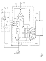
- Figure 1 shows a schematic block diagram for explanation an embodiment of the present invention.
- an input signal 10 in particular a Rectangular signal, which with TTL levels and a pulse repetition frequency (PRF) for example between 1 MHz and 10 MHz is provided in a transmission control signal 11 and reception control signal 12 split.
- the transmission control signal 11 is fed to a delay device 13, which in particular a static delay z. B. means a filter device 14, 15 from a resistor 14 and a capacitor grounded with an electrode 15 provides.
- the delay device has pulse processing 13 a pulse shaper 16, which pulses z. B. generated a length of 400 ps.
- the delay device 13 gives a constantly delayed transmission control signal 17 to trigger a transmission pulse.
- An RF raw signal 18, in particular a received radar raw signal, is fed to a signal processing device 19, in which the radar raw signal 18 is detected and in particular using an algorithm on a digital processor is processed.
- the raw RF signal 18 becomes a delay information signal 20 generated, which is a controllable delay device 21 is supplied.
- One in the signal processing device 19 optionally generated calibration signal 22 is also the controllable delay device 21 fed.
- the controllable delay device 21 delays this Receive drive signal 12 in response to the delay information signal 20, which in particular is a digital word z. B. provides with a word length of 8 bits, and / or depending on the calibration signal 22.
- the controllable delay device 21 shows a linear deceleration curve with a known, i.e. H. adjustable and constant incline, whereby that the actual delay that the controllable Delay device 21 generated, proportional to one set delay runs, with the proportionality factor due to external influences such as B. the temperature or component fluctuations essentially does not change.
- the receive drive signal 12 through the delay means 21 and the externally applied manipulated variables 20, 22 Delayed in a targeted manner.
- the delay information signal 20 is e.g. B. as 8 bit Data word on the inputs 23 to 30 of the controllable delay device 21 fed.
- the controllable delay device 21 becomes the delay information signal 20 preferably stored using TTL latches 31 before the digital data word of the delay information signal 20 in a D / A converter 32 into an analog signal 33, preferably a voltage signal is converted.
- the receive control signal 12 is fed to the controllable delay device 21 via a trigger input 34 and forwarded to a trigger circuit 35, which is also connected on the input side to a reset input 36, via which the trigger circuit 35 can be reset.
- the trigger circuit 35 is followed by a function generator 37, which preferably generates a ramp-shaped signal 39 as a function of the reception control signals 12 supplied via the trigger input 34 and the calibration signal 22 which is input to the controllable delay device 21 via a calibration or offset adaptation input 38 ,
- the function generator 37 or the generated function can preferably be influenced via two further inputs R SET 40 and C EXT 41.
- a comparison device in particular a TTL comparator, compares the ramp-shaped signal 39 with the analog signal 33 and generates a selectively delayed receive drive signal 43, whose delay is proportional to the applied Delay information signal 20.
- the reception drive signal 12 becomes variable with the help of the controllable delay device 21 preferably digitally delayed while the transmit control signal 11 firmly delayed in the delay device 13 becomes.
- the raw radar signal 18 provides the information as to when to the relative delay of the transmit trigger 17 Zero occurs, d. H. what time period passes until the transmission signal of a transmission device as a reception signal / which is received via a receiving device is, directly, d. H. without an object to it To reflect distance determination, is detected. This time can either z. B. by an 8 bit Represent input word 20 and can for the further absolute Distance calculation can be used or directly over the calibration signal 22 of the controllable delay device 21 are supplied, so that for example digital data word 00000000 as delay information signal 20 set to the absolute distance zero becomes.
- FIG. 2 shows a signal diagram to explain the operation an embodiment of the present invention.
- the received radar raw signal 18 is above the Time axis t 44 shown.
- Time 45 describes this simultaneous opening or activation of transmit and receive pulse. Because the shape of the raw signal from sensor to sensor can be different, it is necessary to use an algorithm to provide a reliable of these variations Assigns zero point information.
- the following algorithm is to be calibrated in the signal processing device 19 according to FIG. 1 processed, provided: differentiation of the raw signal 18; Setting a threshold for determining the slope the edge 46 of the raw signal 18, setting the zero point indicator when the threshold is exceeded.
- An offset of this Indicator of the actual zero point at the send and Reception switches are open at the same time, is measured once determined and is essentially from sensor to sensor constant and is included in the calibration.
- each amplitude value of the radar raw signal 18 according to FIG 2 can be assigned a point in time on the time axis 44 can also result in a distance assignment the raw radar signal 18. Scanning for calibration takes place starting from negative distances, the in of the data processing device 19 according to FIG Algorithm the first peak in the output signal as a zero signal recognizes and calculates the exact position of the zero point. Early peaks are physical not possible and consequently the assignment of the zero signal clearly. The measured offset or the measured time delay is saved and all, actually Objects that are detected by the measurement scan are thus corrected.
- the calibration scan makes sense after the detection a temperature change of e.g. B. 5 ° C and / or after performed at a certain time interval.
- a temperature change e.g. B. 5 ° C and / or after performed at a certain time interval.
- the calibration and distance measurement always be carried out together and thus always scanned from negative distances is, the distances of the detected objects in Measurement scan with a zero signal corresponding to the offset, which is recalculated for each scan are corrected.
- the zero point which is opened when the transmit and Receive switch occurs, is not necessarily at the first, second peak or zero crossing.
- controllable delay device which is a component of the company Analog Devices (AD 9501) corresponds, but also with other components e.g. ASICs similar properties can be realized.
Abstract
Description
Die vorliegende Erfindung betrifft ein Verfahren und eine Vorrichtung zum Kalibrieren einer HF-Einrichtung.The present invention relates to a method and a Device for calibrating an HF device.
HF-Systeme werden heute vielfach für Messvorgänge, insbesondere Entfernungs- und Geschwindigkeitsmessungen von Objekten, eingesetzt. Eine besondere Bedeutung kommt dabei der Hochfrequenzmessung (Radar) rundum Fahrzeuge zu. Entfernungsmesseinrichtungen, die zur Erkennung von Entfernungen und Relativgeschwindigkeiten geeignet sind, werden insbesondere als Nahbereichs- Radarsysteme für Automobile vorgesehen. Hierzu wird eine Anzahl von Einzelsensoren an geeigneten Stellen um ein Automobil angeordnet.RF systems are widely used today for measurement processes, in particular Distance and speed measurements of objects, used. This is of particular importance high-frequency measurement (radar) around vehicles. Distance measuring devices the to detect distances and relative speeds are particularly suitable intended as short-range radar systems for automobiles. For this purpose, a number of individual sensors are used Arranged around an automobile.
Ein bekanntes Radar- Frontendsystem mit Namen SRR (Short Range Radar) arbeitet bei einer Frequenz von etwa 24 GHz und erlaubt Entfernungsbestimmungen durch Aussendung und Laufzeitbestimmung von HF-Pulsen, welche z. B. eine typische Breite von 400 ps aufweisen.A well-known radar front-end system called SRR (Short Range Radar) operates at a frequency of around 24 GHz and allows distance determination by sending and Runtime determination of RF pulses, which, for. B. a typical 400 ps wide.
Ein übliches SRR System setzt eine Verzögerungsschaltung ein, die den Empfangspuls gegenüber dem Sendepuls gezielt zeitlich verzögert. Die Verzögerung, die der zu detektierenden Entfernungszelle entspricht, wird durch Anlegen eines vorbestimmten Spannungspegels eingestellt. Zur Vermessung des gesamten Entfernungsbereichs wird die Verzögerungsschaltung vom kleinsten zum größten Wert oder umgekehrt verstellt.A common SRR system uses a delay circuit one that targets the receive pulse versus the transmit pulse delayed. The delay that the to be detected Distance cell corresponds, is created by creating a predetermined voltage level set. For measurement of the entire distance range becomes the delay circuit from the smallest to the greatest value or vice versa adjusted.
Die Genauigkeit mit der die Verzögerungsschaltung eingestellt werden kann, bestimmt maßgeblich die Entfernungsmessgenauigkeit. Für die Bestimmung des Winkels, unter dem ein Objekt insbesondere der Nähe eines Fahrzeugs erkannt werden kann, ist die Vermessung des Objektes mit mindestens zwei Einzelsensoren notwendig. Der Winkelwert kann durch Auswertung der gemessenen Einzelentfernungen mit Hilfe der Triangulation gewonnen werden. Entscheidend für die Winkelmessgenauigkeit ist daher auch die in den Einzelsensoren erzielbare Messgenauigkeit für die Entfernungsmessung.The accuracy with which the delay circuit is set distance measurement accuracy. For determining the angle at which detected an object, particularly in the vicinity of a vehicle is the measurement of the object with at least two individual sensors required. The angle value can by Evaluation of the measured individual distances using the Triangulation can be obtained. Crucial for the angular measurement accuracy is therefore also the one in the individual sensors achievable measurement accuracy for distance measurement.
Um die Messgenauigkeit beispielsweise eines SRR-Systems zu kalibrieren, bedarf es eines Nullabgleichs. Dieser Nullabgleich ist allerdings nur für eine Temperatur und unter identischen äußeren Montagebedingungen gültig. Ist ein solches System eingebaut besteht derzeit keine Möglichkeit das System nachzukalibrieren, woraus inakzeptable absolute Messfehler resultieren. Darüber hinaus ist die Übertragungsfunktion der Verzögerungseinrichtung bzw. -leitung nicht zwingend linear, d. h. selbst wenn man einen nahezu perfekten Nullabgleich erreicht, gilt dieser nur bei der/den Abgleichentfernung(en), da nicht interpoliert werden kann, wenn die Übertragungsfunktion nicht linear ist. Neben Temperatureffekten wirken sich auf ein solches HF-System zusätzlich Bauelementschwankungen und Alterungseffekte der eingesetzten Elemente nachteilig auf die Messgenauigkeit aus.To measure the accuracy of an SRR system, for example calibrate, a zero adjustment is required. This zeroing is only for one temperature and below identical external installation conditions apply. It is one System installed there is currently no possibility that Recalibrate system, resulting in unacceptable absolute Measurement errors result. In addition, the transfer function the delay device or line not necessarily linear, d. H. even if you almost reached perfect zero balance, this only applies to the adjustment distance (s), as they are not interpolated can if the transfer function is not linear. In addition to temperature effects, such an HF system is also affected additional component fluctuations and aging effects of the elements used adversely to the measurement accuracy out.
Das erfindungsgemäße Verfahren bzw. die erfindungsgemäße Vorrichtung zum Kalibrieren eine HF-Einrichtung mit den Merkmalen des Anspruchs 1 weist gegenüber dem bekannten Lösungsansatz den Vorteil auf, dass im Betrieb z. B. des SRR bei Bedarf ein Nullabgleich währen des Messzyklus durchführbar ist. Dadurch kann eine Nachkalibrierung des Systems erfolgen und die Messgenauigkeit kann gesteigert werden.The method according to the invention or the one according to the invention Device for calibrating an HF device with the Features of claim 1 points over the known approach the advantage that in operation z. B. the SRR if necessary, a zero adjustment can be carried out during the measuring cycle is. This can result in recalibration of the system and the measuring accuracy can be increased.
Die der vorliegenden Erfindung zugrundeliegende Idee besteht im Wesentlichen darin, dass man ein Radarsignal ausnützt, welches entsteht, wenn ein Sende- und ein Empfangsschalter gleichzeitig auf Durchgang geschaltet sind. Dann sieht das Radar sich selbst, also z. B. interne Verkopplungen und Antennenüberkopplungen, welche bei der Entfernung von 0 m bzw. bei dem definierten Abstand zwischen Sendeund Empfangseinrichtung auftreten. Diese reproduzierbare Entfernungsinformation des SRR umfasst die Laufzeiten der vollständigen Verzögerungskette, welche die Laufzeiten der Basisbandpulserzeuger, HF-Schalter und Antennen beinhaltet, womit sämtliche Einflüsse dieser Komponenten herauskalibriert werden können. The idea on which the present invention is based exists essentially using a radar signal which arises when a send and a receive switch are switched to continuity at the same time. Then the radar sees itself, e.g. B. internal couplings and antenna overcoupling, which occurs during the removal of 0 m or at the defined distance between transmit and Reception device occur. This reproducible Distance information of the SRR includes the running times of the complete chain of delays covering the terms of the Includes baseband pulse generators, RF switches and antennas, with which all influences of these components are calibrated out can be.
Erfindungsgemäß wird somit zum Kalibrieren einer HF-Einrichtung ein Eingangssignal in ein Sendeansteuersignal und ein Empfangsansteuersignal aufgespalten, das Sendeansteuersignal in einer Verzögerungseinrichtung zum Triggern eines Sendepulses verzögert, das Empfangsansteuersignal in Abhängigkeit eines Verzögerungsformationssignals und/oder eines Kalibrierungssignals in einer steuerbaren Verzögerungseinrichtung zum selektiven Triggern eines Empfangspulses selektiv verzögert, und ein HF-Rohsignal, insbesondere ein empfangenes Radarsignal, in das Verzögerungsinformationssignal und/oder das Kalibrierungssignal in einer Signalverarbeitungseinrichtung zum Kalibrieren der HF-Einrichtung abgetastet und verarbeitet.According to the invention, this is used to calibrate an HF device an input signal in a transmission control signal and a receive drive signal is split, the transmit drive signal in a delay device for triggering of a transmit pulse is delayed, the receive drive signal in Dependence of a delay formation signal and / or a calibration signal in a controllable delay device for selective triggering of a receive pulse selectively delayed, and an RF raw signal, in particular a received radar signal into the delay information signal and / or the calibration signal in a signal processing device for calibrating the HF device scanned and processed.
In den Unteransprüchen finden sich vorteilhafte Weiterbildungen
und Verbesserungen des in Anspruch 1 angegebenen
Verfahrens bzw. der in Anspruch 10 angegebenen Vorrichtung
zur Kalibrierung einer HF-Einrichtung.Advantageous further developments can be found in the subclaims
and improvements to that specified in claim 1
Method or the device specified in
Gemäß einer bevorzugten Weiterbildung wird in der Signalverarbeitungseinrichtung aus dem HF-Rohsignal in Abhängigkeit der vorliegenden Verzögerung des Sendeansteuersignals ein absoluter Nullpunkt und somit ein Offset der HF- Einrichtung ermittelt, bei welchem sowohl der Sendepuls als auch der Empfangspuls gleichzeitig aktiviert werden. Dies hat den Vorteil, dass die Laufzeit der gesamten Verzögerungskette bestimmbar wird und folglich sämtliche Einflüsse dieser Komponenten herauskalibriert werden können. According to a preferred development, the signal processing device dependent on the raw RF signal the present delay of the transmission control signal an absolute zero point and thus an offset of the HF device determined in which both the transmission pulse as the reception pulse can also be activated at the same time. This has the advantage that the running time of the entire delay chain becomes determinable and consequently all influences of these components can be calibrated out.
Gemäß einer weiteren bevorzugten Weiterbildung wird zum Ermitteln des absoluten Nullpunks das HF-Rohsignal differenziert, ein Schwellwert zur Bestimmung der Steigung einer Flanke des HF-Rohsignals bestimmt, und wenn der Schwellwert überschritten wird, wird an dieser Stelle der absolute Nullpunkt bzw. der Offset aus dem HF-Rohsignal bestimmt. Vorteilhaft an diesem Algorithmus ist, dass damit die von Sensor zu Sensor unterschiedlich ausfallenden Formen des Rohsignals trotz auftretender Variationen eine zuverlässige Nullpunktsinformation zuordnen kann.According to a further preferred development, determination is carried out differentiates the raw RF signal from the absolute zero point, a threshold for determining the slope of a Edge of the RF raw signal is determined and if the threshold is exceeded, the absolute becomes at this point Zero point or the offset is determined from the raw RF signal. The advantage of this algorithm is that it is used by Sensor to sensor different forms of the Raw signal a reliable despite occurring variations Can assign zero point information.
Gemäß einer weiteren bevorzugten Weiterbildung wird auf Basis des ermittelten Nullpunkts bzw. des Offsets die selektive Verzögerung des Empfangsansteuersignals in der steuerbaren Verzögerungseinrichtung zur Kalibrierung bzw. zum Nullabgleich der HF-Einrichtung angepasst. Dies ermöglicht das eigentliche Herauskalibrieren der unerwünscht auftretenden Effekte wie z. B. die Temperaturabhängigkeit.According to a further preferred development, based on of the determined zero point or the offset the selective Delay of the receive control signal in the controllable Delay device for calibration or Adjusted zero adjustment of the HF device. this makes possible the actual calibration out of the undesirable ones Effects such as B. the temperature dependence.
Gemäß einer weiteren bevorzugten Weiterbildung erfolgt die Kalibrierung über das Kalibrierungssignal, insbesondere ein Spannungssignal, welches einem Offsetsteuereingang der steuerbaren Verzögerungseinrichtung zugeführt wird. Dadurch wird es möglich den detektierten Offset nicht über das Verzögerungsinformationssignal zu steuern und damit den Scan-Bereich nicht einzuschränken, sondern die Offsetverstellung bzw. Nullpunktkalibrierung mittels des Kalibrierungssignals separat vorzunehmen. According to a further preferred development, the Calibration via the calibration signal, in particular a Voltage signal, which an offset control input of controllable delay device is supplied. Thereby the detected offset will not be possible via the delay information signal to control and thus the scan area not to restrict, but the offset adjustment or zero point calibration using the calibration signal to be carried out separately.
Gemäß einer weiteren bevorzugten Weiterbildung ist das der steuerbaren Verzögerungseinrichtung zugeführte Verzögerungsinformationssignal ein Digitalwort, welches insbesondere eine Länge von 8 Bit aufweist. Dies hat den Vorteil, dass das in der Signalverarbeitungseinrichtung generierte Verzögerungsinformationssignal mit Hilfe eines Mikroprozessors bearbeitet werden kann.According to a further preferred development, this is the controllable delay device supplied delay information signal a digital word, which in particular has a length of 8 bits. This has the advantage that that generated in the signal processing device Delay information signal using a microprocessor can be edited.
Gemäß einer weitern bevorzugten Weiterbildung wird die Kalibrierung der HF-Einrichtung nach einer von außen detektierten vorbestimmten Temperaturänderung und/oder nach einem vorbestimmten Zeitintervall durchgeführt. Dadurch wird sichergestellt, dass die HF-Einrichtung vor allem bei kritischen Temperaturänderungen aber auch in gewissen zeitlichen Abständen nachkalibriert wird.According to a further preferred development, the calibration the HF device after one detected from the outside predetermined temperature change and / or after a predetermined time interval performed. This will ensures that the RF device is especially critical Temperature changes also in certain temporal Intervals is recalibrated.
Gemäß einer weiteren bevorzugten Weiterbildung wird die selbstkalibrierende HF-Einrichtung zur Entfernungs- und / oder Geschwindigkeitsbestimmung von Objekten, insbesondere mit Nahbereichs-Pulsradar, eingesetzt. Dies birgt den Vorteil, dass aufgrund der Kalibrierungsmöglichkeit der HF-Einrichtung im Messeinsatz präzise, reproduzierbare Messergebnisse erzielt werden.According to a further preferred development, the self-calibrating HF device for Distance and / or speed determination of objects, in particular with short-range pulse radar. This has the advantage that due to the possibility of calibration of the HF device precise, reproducible measurement results in the measuring insert be achieved.
Gemäß einer weiteren bevorzugten Weiterbildung wird die Selbstkalibrierung der HF-Einrichtung bei und/oder vor jeder Entfernungsmessung der HF-Einrichtung durchgeführt. Dadurch wird eine permanente Nachkalibrierung der Anordnung ermöglicht.According to a further preferred development, the Self-calibration of the HF device at and / or in front of everyone Distance measurement of the HF device carried out. Thereby becomes a permanent recalibration of the arrangement allows.
Gemäß einer weiteren bevorzugten Weiterbildung sieht die Verzögerungseinrichtung eine statische Verzögerung vor, welche insbesondere eine Filtereinrichtung z. B. aus einem Widerstand und einem Kondensator besteht und/oder einen Pulsformer aufweist. Durch die somit bereitgestellte statische Verzögerung wird das Sendeansteuersignal vorteilhaft um eine bestimmte, bekannte Zeitperiode zeitlich verzögert sowie Sendepulse einer vorbestimmten Länge vorgesehen.According to a further preferred development, the Delay device a static delay before which in particular a filter device z. B. from one Resistor and a capacitor and / or one Has pulse shaper. Due to the static provided Delay, the transmission control signal is advantageous delayed by a certain known time period and transmit pulses of a predetermined length are provided.
Gemäß einer weiteren bevorzugten Weiterbildung umfasst die Signalverarbeitungseinrichtung einen Prozessor, auf welchem ein Algorithmus zum Bestimmen eines Nullpunkts bzw. Offsets aus dem HF-Rohsignal abarbeitbar ist. Dies birgt den Vorteil der digitalen Datenverarbeitung und somit eine mögliche Miniaturisierung der Signalverarbeitungseinrichtung.According to a further preferred development, the Signal processing device a processor on which an algorithm for determining a zero point or offset can be processed from the raw RF signal. This has the advantage of digital data processing and thus a possible one Miniaturization of the signal processing device.
Gemäß einer weiteren bevorzugten Weiterbildung weist die steuerbare Verzögerungseinrichtung eine Digital / Analog Umwandlungseinrichtung zum Umwandeln des digitalen Verzögerungsinformationssignals in ein Analogsignal, insbesondere in ein analoges Spannungssignal, auf. Dadurch wird eine analoge Weiterverarbeitung des Verzögerungsinformationssignals in der steuerbaren Verzögerungseinrichtung ermöglicht. According to a further preferred development, the controllable delay device a digital / analog Converting means for converting the digital delay information signal into an analog signal, in particular into an analog voltage signal. This will make one analogue processing of the delay information signal in the controllable delay device.
Gemäß einer weiteren bevorzugten Weiterbildung weist die steuerbare Verzögerungseinrichtung einen Funktionsgenerator zum Erzeugen eines rampenförmigen Signals aus dem Empfangsansteuersignal in Abhängigkeit von dem Kalibrierungssignal auf. Dies ermöglicht die vorteilhafte Offset-Kalibrierung separat von der eigentlichen steuerbaren Verzögerung zum Erfassen des Scan-Bereichs.According to a further preferred development, the controllable delay device a function generator for generating a ramp-shaped signal from the reception drive signal depending on the calibration signal on. This enables the advantageous offset calibration separate from the actual controllable delay to Capture the scan area.
Gemäß einer weiteren bevorzugten Weiterbildung weist die steuerbare Verzögerungseinrichtung einen Komparator, insbesondere einen TTL-Komparator, zum Vergleichen des rampenförmigen Signals mit dem Analogsignal und zum Ausgeben eines Vergleichssignals auf. Dadurch wird eine steuerbare Verzögerung des Empfangsansteuersignals sichergestellt.According to a further preferred development, the controllable delay device, a comparator, in particular a TTL comparator to compare the ramp-shaped Signal with the analog signal and to output a Comparison signal. This makes it controllable Delay of the receive control signal ensured.
Gemäß einer weiteren bevorzugten Weiterbildung sieht die steuerbare Verzögerungseinrichtung einen linearen Verzögerungsverlauf mit konstanter und bekannter Steigerung proportional zu dem Verzögerungsinformationssignal vor. Dies hat den Vorteil, dass durch Signalgrößenänderungen direkt proportionale, lineare Verzögerungen des Empfangsansteuersignals erzielt werden.According to a further preferred development, the controllable delay device a linear delay curve proportional with constant and known increase to the delay information signal. This has the advantage that directly through signal size changes proportional, linear delays of the receive control signal be achieved.
Gemäß einer weiteren bevorzugten Weiterbildung sind das Sendeansteuersignal und das Empfangsansteuersignal mit einer Pulswiederholfrequenz (PRF) beaufschlagte Rechtecksignale mit TTL-Pegeln, z. B. in einem Wiederholratenfrequenzbereich von 1 MHz bis 10 MHz. Dadurch werden für SSR-Systeme übliche Pulsmuster ermöglicht. According to a further preferred development, these are Transmit control signal and the receive control signal with a Pulse repetition rate (PRF) applied square wave signals with TTL levels, e.g. B. in a repetition rate frequency range from 1 MHz to 10 MHz. This makes for SSR systems usual pulse pattern allows.
Ausführungsbeispiele der Erfindung sind in den Zeichnungen dargestellt und in der nachfolgenden Beschreibung näher erläutert.Embodiments of the invention are in the drawings shown and explained in more detail in the following description.
Es zeigen:
- Fig. 1
- ein schematisches Blockdiagramm zur Erläuterung einer Ausführungsform der vorliegenden Erfindung; und
- Fig. 2
- ein Signalschaubild zur Erläuterung einer Funktionsweise einer Ausführungsform der vorliegenden Erfindung.
- Fig. 1
- a schematic block diagram for explaining an embodiment of the present invention; and
- Fig. 2
- a signal diagram for explaining an operation of an embodiment of the present invention.
In den Figuren bezeichnen gleiche Bezugszeichen gleiche oder funktionsgleiche Bestandteile.In the figures, the same reference symbols denote the same or functionally identical components.
Figur 1 zeigt ein schematisches Blockdiagramm zur Erläuterung einer Ausführungsform der vorliegenden Erfindung.Figure 1 shows a schematic block diagram for explanation an embodiment of the present invention.
In Figur 1 wird ein Eingangssignal 10, insbesondere ein
Rechtecksignal, welches mit TTL-Pegeln und einer Pulswiederholfrequenz
(PRF) beispielsweise zwischen 1 MHz und 10
MHz versehen ist, in ein Sendeansteuersignal 11 und Empfangsansteuersignal
12 aufgespaltet. Das Sendeansteuersignal
11 wird einer Verzögerungseinrichtung 13 zugeführt,
welche insbesondere eine statische Verzögerung z. B. mittels
einer Filtereinrichtung 14, 15 aus einem Widerstand 14
und einem mit einer Elektrode auf Masse gelegten Kondensator
15 vorsieht. Zur Pulsaufbereitung weist die Verzögerungseinrichtung
13 einen Pulsformer 16 auf, welcher Pulse
z. B. einer Länge von 400 ps erzeugt. Die Verzögerungseinrichtung
13 gibt ein konstant verzögertes Sendeansteuersignal
17 zum Triggern eines Sendepulses aus.In Figure 1, an
Ein HF-Rohsignal 18, insbesondere ein empfangenes Radarrohsignal,
wird einer Signalverarbeitungseinrichtung 19 zugeführt,
in welcher das Radarrohsignal 18 erfasst und insbesondere
mit Hilfe eines Algorithmus auf einem Digitalprozessor
bearbeitet wird. In der Signalverarbeitungseinrichtung
19 wird aus dem HF-Rohsignal 18 ein Verzögerungsinformationssignal
20 erzeugt, welches einer steuerbaren Verzögerungseinrichtung
21 zugeführt wird. Ein in der Signalverarbeitungseinrichtung
19 optional erzeugtes Kalibrierungssignal
22 wird ebenfalls der steuerbaren Verzögerungseinrichtung
21 zugeführt.An RF
Die steuerbare Verzögerungseinrichtung 21 verzögert das
Empfangsansteuersignal 12 in Abhängigkeit von dem Verzögerungsinformationssignals
20, welches insbesondere ein Digitalwort
z. B. mit einer Wortlänge von 8 Bit vorsieht,
und/oder in Abhängigkeit von dem Kalibrierungssignal 22.
Vorzugsweise stellt die steuerbare Verzögerungseinrichtung
21 einen linearen Verzögerungsverlauf mit bekannter, d. h.
einstellbarer und konstanter Steigung bereit, wobei gilt,
dass die tatsächliche Verzögerung, welche die steuerbare
Verzögerungseinrichtung 21 generiert, proportional zu einer
eingestellten Verzögerung verläuft, wobei sich der Proportionalitätsfaktor
aufgrund von äußeren Einflüssen wie z. B.
der Temperatur oder Bauteilschwankungen im Wesentlichen
nicht ändert. Im Gegensatz zum konstant verzögerten Signal
17 zum Triggern eines Sendeschalters (nicht dargestellt)
wird das Empfangsansteuersignal 12 durch die Verzögerungseinrichtung
21 und die externen angelegten Stellgrößen 20,
22 zeitlich gezielt verzögert.The
Das Verzögerungsinformationssignal 20 wird z. B. als 8 bit
Datenwort den Eingängen 23 bis 30 der steuerbaren Verzögerungseinrichtung
21 zugeführt. In der steuerbaren Verzögerungseinrichtung
21 wird das Verzögerungsinformationssignal
20 vorzugsweise mittels TTL-Latches 31 gespeichert, bevor
das digitale Datenwort des Verzögerungsinformationssignals
20 in einem D/A-Wandler 32 in ein analoges Signal 33, vorzugsweise
ein Spannungssignal umgewandelt wird.The
Das Empfangsansteuersignal 12 wird der steuerbare Verzögerungseinrichtung
21 über einen Triggereingang 34 zugeführt
und an eine Triggerschaltung 35 weitergeleitet, welche eingangsseitig
ebenfalls mit einem Reseteingang 36 verbunden
ist, über welchen die Triggerschaltung 35 rückstellbar ist.
An die Triggerschaltung 35 schließt sich ein Funktionsgenerator
37 an, welcher in Abhängigkeit von dem über den Triggereingang
34 zugeführten Empfangsansteuersignalen 12 und
dem Kalibrierungssignals 22, welches der steuerbaren Verzögerungseinrichtung
21 über einen Kalibrierungs- bzw. Offsetanpasseingang
38 eingegeben wird, vorzugsweise ein rampenförmiges
Signal 39 erzeugt. Der Funktionsgenerator 37
bzw. die generierte Funktion ist vorzugsweise über zwei
weitere Eingänge RSET 40 und CEXT 41 beeinflussbar.The receive
Eine Vergleichseinrichtung, insbesondere ein TTL- Komparator,
vergleicht das rampenförmige Signal 39 mit dem Analogsignal
33 und erzeugt ein selektiv verzögertes Empfangsansteuersignal
43, dessen Verzögerung proportional zum angelegten
Verzögerungsinformationssignal 20 ist.A comparison device, in particular a TTL comparator,
compares the ramp-shaped
Da zum Herauskalibrieren der temperatur- und bauteilabhängigen
Gesamtsignallaufzeit das empfangsseitige Triggersignal
12 relativ zum Triggersignal 11 des Sendezweiges verzögert
werden muss, wird das Empfangsansteuersignal 12 variabel
mit Hilfe der steuerbaren Verzögerungseinrichtung 21
vorzugsweise digital verzögert, während das Sendeansteuersignal
11 in der Verzögerungseinrichtung 13 fest verzögert
wird.Because to calibrate out the temperature and component dependent
Total signal transit time of the trigger signal at the receiving
Das Radar-Rohsignal 18 liefert die Information, wann bezogen
auf die relative Verzögerung des Sendetriggers 17 der
Nullpunkt auftritt, d. h. welche Zeitperiode verstreicht
bis das Sendesignal einer Sendeeinrichtung als Empfangssignal/
welches über eine Empfangseinrichtung aufgenommen
wird, auf direktem Wege, d. h. ohne an einem Objekt zu dessen
Entfernungsbestimmung zu reflektieren, detektiert wird.
Dieser Zeitpunkt lässt sich entweder z. B. durch ein 8 Bit
Eingangswort 20 darstellen und kann für die weitere absolute
Entfernungsberechnung verwendet werden oder direkt über
das Kalibrierungssignal 22 der steuerbaren Verzögerungseinrichtung
21 zugeführt werden, so dass beispielsweise das
digitale Datenwort 00000000 als Verzögerungsinformationssignal
20 auf den absoluten Entfernungsnullpunkt gesetzt
wird.The
Figur 2 zeigt ein Signalschaubild zur Erläuterung der Funktionsweise einer Ausführungsform der vorliegenden Erfindung.Figure 2 shows a signal diagram to explain the operation an embodiment of the present invention.
In Figur 2 ist das empfangene Radar- Rohsignal 18 über der
Zeitachse t 44 dargestellt. Der Zeitpunkt 45 beschreibt das
gleichzeitige Öffnen bzw. Aktivieren von Sende- und Empfangspuls.
Da die Form des Rohsignals von Sensor zu Sensor
unterschiedlich ausfallen kann, ist es notwendig, einen Algorithmus
vorzusehen, der diesen Variationen eine zuverlässige
Nullpunktinformation zuordnet.In Figure 2, the received radar
Da insbesondere die Amplitude des Nullsignals und die Auslenkungsrichtung
des ersten Schwingungsbauches unterschiedlich
sind, bietet sich an, das Rohsignal 18 zu differenzieren
und nur die jeweiligen Flanken 46 des Rohsignals 18 zu
betrachten. Nimmt man dann den Betrag der Ableitung, so ist
es nicht mehr relevant, ob zuerst eine positive oder negative
Auslenkung des Signals erfolgt. In Messungen hat sich
bestätigt, dass die Flankensteilheit der ersten Auslenkung
gut reproduzierbar ist.Because in particular the amplitude of the zero signal and the direction of deflection
of the first antinode different
are, it makes sense to differentiate the
Zum detektieren des absoluten Entfernungsnullpunkts aus dem
Radar-Rohsignal 18, um damit eine erfindungsgemäße HF-Einrichtung
zu kalibrieren ist folgender Algorithmus, welcher
in der Signalverarbeitungseinrichtung 19 nach Figur 1
abgearbeitet wird, vorgesehen: Differenziation des Rohsignals
18; Setzen einer Schwelle zur Bestimmung der Steigung
der Flanke 46 des Rohsignals 18, Setzen des Nullpunktsindikators
bei Überschreiten der Schwelle. Ein Offset dieses
Indikators zum tatsächlichen Nullpunkt, bei der Sende- und
Empfangsschalter gleichzeitig offen sind, wird messtechnisch
einmal bestimmt und ist von Sensor zu Sensor im Wesentlichen
konstant und wird bei der Kalibrierung mit eingerechnet.To detect the absolute zero point from the
Radar
Da jedem Amplitudenwert des Radar-Rohsignals 18 gemäß Figur
2 ein Zeitpunkt auf der Zeitachse 44 zugeordnet werden
kann, ergibt sich ebenfalls eine Entfernungszuordnung aus
dem Radar-Rohsignal 18. Das Scannen für die Kalibrierung
erfolgt beginnend von negativen Entfernungen, wobei der in
der Datenverarbeitungseinrichtung 19 nach Figur 1 ablaufende
Algorithmus den ersten Peak im Ausgangssignal als Nullsignal
erkennt und die exakte Position des Nullpunkts errechnet.
Zeitlich früh auftretende Peaks sind physikalisch
nicht möglich und die Zuordnung des Nullsignals folglich
eindeutig. Der gemessene Offset bzw. die gemessene Zeitverzögerung
wird gespeichert und sämtliche, im eigentlichen
Mess-Scan detektierten Objekte werden damit korrigiert.Since each amplitude value of the radar
Der Kalibrierungs-Scan wird sinnvollerweise nach der Detektion einer Temperaturänderung von z. B. 5° C und/oder nach einem bestimmten Zeitintervall durchgeführt. Bei ausreichender Rechenleistung der Signalverarbeitungseinrichtung ist ebenfalls denkbar, dass die Kalibrierung und die Entfernungsmessung immer zusammen durchgeführt werden und somit immer von negativen Entfernungen beginnend gescannt wird, wobei die Entfernungen der detektierten Objekte im Mess-Scan mit einem dem Offset entsprechenden Nullsignal, welches für jeden Scan neu berechnet wird, korrigiert werden.The calibration scan makes sense after the detection a temperature change of e.g. B. 5 ° C and / or after performed at a certain time interval. With sufficient Computing power of the signal processing device it is also conceivable that the calibration and distance measurement always be carried out together and thus always scanned from negative distances is, the distances of the detected objects in Measurement scan with a zero signal corresponding to the offset, which is recalculated for each scan are corrected.
Der Nullpunkt, welcher bei gleichzeitigem Öffnen von Sendeund Empfangsschalter auftritt, liegt nicht notwendigerweise bei dem ersten, zweiten Peak oder dem Nulldurchgang.The zero point, which is opened when the transmit and Receive switch occurs, is not necessarily at the first, second peak or zero crossing.
Obwohl die vorliegende Erfindung vorstehend anhand eines bevorzugten Ausführungsbeispiels beschrieben wurde, ist sie darauf nicht beschränkt, sondern auf vielfältige Weise modifizierbar.Although the present invention has been described above with reference to a preferred embodiment has been described, it is not limited to this, but can be modified in a variety of ways.
Die Erfindung ist insbesondere nicht beschränkt auf die exemplarisch verwendete, steuerbare Verzögerungseinrichtung, welche einem Baustein der Firma Analog Devices (AD 9501) entspricht, sondern auch mit anderen Bausteinen z.B. ASICs ähnlicher Eigenschaften realisierbar.The invention is in particular not limited to the examples controllable delay device used, which is a component of the company Analog Devices (AD 9501) corresponds, but also with other components e.g. ASICs similar properties can be realized.
Claims (19)
dadurch gekennzeichnet, dass in der Signalverarbeitungseinrichtung (19) aus dem HF- Rohsignal (18) in Abhängigkeit der vorliegenden Verzögerung des Sendeansteuersignals (17) ein absoluter Nullpunkt und somit ein Offset der HF-Einrichtung ermittelt wird, bei welchem sowohl der Sendepuls (17) als auch der Empfangspuls (43) gleichzeitig aktiviert werden.Method according to claim 1,
characterized in that an absolute zero point and thus an offset of the HF device is determined in the signal processing device (19) from the raw HF signal (18) depending on the existing delay of the transmit control signal (17), in which both the transmit pulse (17) and the reception pulse (43) can be activated simultaneously.
dadurch gekennzeichnet, dass zum Ermitteln des absoluten Nullpunkts das HF-Rohsignal (18) differenziert wird, ein Schwellwert zur Bestimmung der Steigung einer Flanke (46) des HF- Rohsignals (18) bestimmt wird, und wenn dieser Schwellwert überschritten wird an dieser Stelle der absolute Nullpunkt bzw. der Offset aus dem HF- Rohsignal (18) bestimmt wird.Method according to claim 2,
characterized in that the raw RF signal (18) is differentiated to determine the absolute zero, a threshold value for determining the slope of an edge (46) of the raw RF signal (18) is determined, and if this threshold value is exceeded at this point absolute zero or the offset is determined from the HF raw signal (18).
dadurch gekennzeichnet, dass auf Basis des ermittelten Nullpunktes bzw. des Offsets die selektive Verzögerung des Empfangsansteuersignals (12) in der steuerbaren Verzögerungseinrichtung (21) zur Kalibrierung bzw. zum Nullabgleich der HF-Einrichtung angepasst wird. Method according to one of the preceding claims 2 or 3,
characterized in that, on the basis of the determined zero point or the offset, the selective delay of the reception control signal (12) in the controllable delay device (21) is adapted for calibration or for zero adjustment of the HF device.
dadurch gekennzeichnet, dass die Kalibrierung über das Kalibrierungssignal (22), insbesondere ein Spannungssignal, erfolgt, welches einem Offsetsteuereingang (38) der steuerbaren Verzögerungseinrichtung (21) zugeführt wird.Method according to claim 4,
characterized in that the calibration takes place via the calibration signal (22), in particular a voltage signal, which is fed to an offset control input (38) of the controllable delay device (21).
dadurch gekennzeichnet, dass das der steuerbaren Verzögerungseinrichtung (21) zugeführte Verzögerungsinformationssignal (20) ein Digitalwort ist, welches insbesondere eine Länge von 8-bit aufweist.Method according to one of the preceding claims,
characterized in that the delay information signal (20) supplied to the controllable delay device (21) is a digital word which in particular has a length of 8 bits.
dadurch gekennzeichnet, dass die Kalibrierung der HF-Einrichtung nach einer von außen detektierten vorbestimmten Temperaturänderung und/oder nach einem vorbestimmten Zeitintervall durchgeführt wird.Method according to one of the preceding claims,
characterized in that the calibration of the HF device is carried out after a predetermined temperature change detected from the outside and / or after a predetermined time interval.
dadurch gekennzeichnet, dass die selbstkalibrierende HF-Einrichtung zur Entfernungs- und/oder Geschwindigkeitsbestimmung von Objekten, insbesondere mit einem Nahbereichs Pulsradar, eingesetzt wird. Method according to one of the preceding claims,
characterized in that the self-calibrating HF device is used for determining the distance and / or speed of objects, in particular with a short-range pulse radar.
dadurch gekennzeichnet, dass die Selbstkalibrierung der HF-Einrichtung bei und/oder vor jeder Entfernungsmessung der HF-Einrichtung durchgeführt wird.A method according to claim 8,
characterized in that the self-calibration of the HF device is carried out during and / or before each distance measurement of the HF device.
dadurch gekennzeichnet, dass die Verzögerungseinrichtung (13) eine statische Verzögerung vorsieht, welche insbesondere eine Filtereinrichtung (14, 15) z. B. aus einem Widerstand (14) und einem Kondensator (15) und/oder einen Pulsformer (16) aufweist.Device according to claim 10,
characterized in that the delay device (13) provides a static delay, which in particular a filter device (14, 15) z. B. from a resistor (14) and a capacitor (15) and / or a pulse shaper (16).
dadurch gekennzeichnet, dass die Signalverarbeitungseinrichtung (19) einen Prozessor aufweist, auf welchem ein Algorithmus zum Bestimmen eines Nullpunkts bzw. Offsets aus dem HF-Rohsignal abarbeitbar ist.Device according to one of the preceding claims 10, 11,
characterized in that the signal processing device (19) has a processor on which an algorithm for determining a zero point or offset from the raw RF signal can be processed.
dadurch gekennzeichnet, dass die steuerbare Verzögerungseinrichtung (21) mindestens einen Eingang (23 bis 30) zum Zuführen des Verzögerungsinformationssignals (20) aufweist, welches insbesondere digital in einer TTL- Latch- Speichereinrichtung (31) speicherbar ist.Device according to one of the preceding claims 10 to 12,
characterized in that the controllable delay device (21) has at least one input (23 to 30) for supplying the delay information signal (20), which in particular can be stored digitally in a TTL latch memory device (31).
dadurch gekennzeichnet, dass die steuerbare Verzögerungseinrichtung (21) eine digital/analog Umwandlungseinrichtung (32) zum Umwandeln des digitalen Verzögerungsinformationssignals (20) in ein Analogsignal (33), insbesondere ein analoges Spannungssignal, aufweist. Device according to one of the preceding claims 10 to 13,
characterized in that the controllable delay device (21) has a digital / analog conversion device (32) for converting the digital delay information signal (20) into an analog signal (33), in particular an analog voltage signal.
dadurch gekennzeichnet, dass die steuerbare Verzögerungseinrichtung (21) einen Funktionsgenerator (37) zum Erzeugen eines rampenförmigen Signals (39) aus dem Empfangsansteuersignal (12) in Abhängigkeit von dem Kalibrierungssignal (22) aufweist.Device according to one of the preceding claims 10 to 14,
characterized in that the controllable delay device (21) has a function generator (37) for generating a ramp-shaped signal (39) from the receive control signal (12) as a function of the calibration signal (22).
dadurch gekennzeichnet, dass die steuerbare Verzögerungseinrichtung (21) eine Vergleichseinrichtung (42), insbesondere einen TTL-Komparator, zum Vergleichen des rampenförmigen Signals (39) mit dem Analogsignal (33) und zum Ausgeben eines Vergleichssignals (43) aufweist.Device according to claim 15,
characterized in that the controllable delay device (21) has a comparison device (42), in particular a TTL comparator, for comparing the ramp-shaped signal (39) with the analog signal (33) and for outputting a comparison signal (43).
dadurch gekennzeichnet, dass die steuerbare Verzögerungseinrichtung (21) einen linearen Verzögerungsverlauf mit konstanter und bekannter Steigung proportional zu dem Verzögerungsinformationssignal (20) vorsieht.Device according to one of the preceding claims 10 to 16,
characterized in that the controllable delay device (21) provides a linear delay curve with a constant and known gradient proportional to the delay information signal (20).
dadurch gekennzeichnet, dass die Vorrichtung in einem System zum Bestimmen des Abstandes und/oder der Geschwindigkeit eines Objektes, insbesondere mit einem Nahbereichs Pulsradar, vorgesehen ist.Device according to one of the preceding claims 10 to 17,
characterized in that the device is provided in a system for determining the distance and / or the speed of an object, in particular with a short-range pulse radar.
dadurch gekennzeichnet, dass das Sendeansteuersignal (11) und das Empfangsansteuersignal (12) mit einer Pulswiederholfrequenz (PRF) beaufschlagte Rechtecksignale mit TTL-Pegeln, z.B. in einem Wiederholratenfrequenzbereich von 1 MHz bis 10 MHz, sind.Device according to one of the preceding claims 10 to 18,
characterized in that the transmit control signal (11) and the receive control signal (12) are square-wave signals applied with a pulse repetition frequency (PRF) with TTL levels, for example in a repetition rate frequency range from 1 MHz to 10 MHz.
Applications Claiming Priority (2)
| Application Number | Priority Date | Filing Date | Title |
|---|---|---|---|
| DE2002127822 DE10227822A1 (en) | 2002-06-21 | 2002-06-21 | Method and device for calibrating an HF device |
| DE10227822 | 2002-06-21 |
Publications (2)
| Publication Number | Publication Date |
|---|---|
| EP1376152A2 true EP1376152A2 (en) | 2004-01-02 |
| EP1376152A3 EP1376152A3 (en) | 2004-03-31 |
Family
ID=29716586
Family Applications (1)
| Application Number | Title | Priority Date | Filing Date |
|---|---|---|---|
| EP03007608A Withdrawn EP1376152A3 (en) | 2002-06-21 | 2003-04-02 | Method and device for calibrating an HF-device |
Country Status (2)
| Country | Link |
|---|---|
| EP (1) | EP1376152A3 (en) |
| DE (1) | DE10227822A1 (en) |
Cited By (4)
| Publication number | Priority date | Publication date | Assignee | Title |
|---|---|---|---|---|
| EP1566656A2 (en) * | 2004-02-17 | 2005-08-24 | Fujitsu Ten Limited | Radar apparatus |
| EP1981120A1 (en) * | 2007-04-09 | 2008-10-15 | Honeywell International Inc. | Method for phase calibrating antennas in a radar system |
| CN109375196A (en) * | 2018-12-12 | 2019-02-22 | 北京华科博创科技有限公司 | A kind of laser radar caliberating device and scaling method based on space-time transformation |
| CN110462532A (en) * | 2017-03-20 | 2019-11-15 | 贝美克斯公司 | The automatic calibration of measuring circuit |
Citations (3)
| Publication number | Priority date | Publication date | Assignee | Title |
|---|---|---|---|---|
| EP0928974A2 (en) * | 1998-01-09 | 1999-07-14 | Endress + Hauser Gmbh + Co. | Partial probe mapping |
| WO1999063362A1 (en) * | 1998-05-29 | 1999-12-09 | Robert Bosch Gmbh | Sampler control device |
| WO2000077542A1 (en) * | 1999-06-11 | 2000-12-21 | S.M.S. Smart Microwave Sensors Gmbh | Distance measuring device and method for calibrating a distance measuring device |
-
2002
- 2002-06-21 DE DE2002127822 patent/DE10227822A1/en not_active Withdrawn
-
2003
- 2003-04-02 EP EP03007608A patent/EP1376152A3/en not_active Withdrawn
Patent Citations (3)
| Publication number | Priority date | Publication date | Assignee | Title |
|---|---|---|---|---|
| EP0928974A2 (en) * | 1998-01-09 | 1999-07-14 | Endress + Hauser Gmbh + Co. | Partial probe mapping |
| WO1999063362A1 (en) * | 1998-05-29 | 1999-12-09 | Robert Bosch Gmbh | Sampler control device |
| WO2000077542A1 (en) * | 1999-06-11 | 2000-12-21 | S.M.S. Smart Microwave Sensors Gmbh | Distance measuring device and method for calibrating a distance measuring device |
Cited By (8)
| Publication number | Priority date | Publication date | Assignee | Title |
|---|---|---|---|---|
| EP1566656A2 (en) * | 2004-02-17 | 2005-08-24 | Fujitsu Ten Limited | Radar apparatus |
| EP1566656A3 (en) * | 2004-02-17 | 2006-07-26 | Fujitsu Ten Limited | Radar apparatus |
| US7529290B2 (en) | 2004-02-17 | 2009-05-05 | Fujitsu Ten Limited | Radar apparatus |
| EP1981120A1 (en) * | 2007-04-09 | 2008-10-15 | Honeywell International Inc. | Method for phase calibrating antennas in a radar system |
| US7522096B2 (en) | 2007-04-09 | 2009-04-21 | Honeywell International Inc | Method for phase calibrating antennas in a radar system |
| CN110462532A (en) * | 2017-03-20 | 2019-11-15 | 贝美克斯公司 | The automatic calibration of measuring circuit |
| CN109375196A (en) * | 2018-12-12 | 2019-02-22 | 北京华科博创科技有限公司 | A kind of laser radar caliberating device and scaling method based on space-time transformation |
| CN109375196B (en) * | 2018-12-12 | 2019-08-20 | 北京华科博创科技有限公司 | A kind of laser radar caliberating device and scaling method based on space-time transformation |
Also Published As
| Publication number | Publication date |
|---|---|
| EP1376152A3 (en) | 2004-03-31 |
| DE10227822A1 (en) | 2004-01-08 |
Similar Documents
| Publication | Publication Date | Title |
|---|---|---|
| EP1141744B1 (en) | Method for detecting and correcting non-linearities of high-frequency voltage-controlled oscillators | |
| EP1395846B1 (en) | Method and device for self-calibration of a radar sensor arrangement | |
| DE102007030978B4 (en) | radar device | |
| DE10055457B4 (en) | Device for detecting a radar characteristic | |
| DE69825204T2 (en) | Self-calibration of an oscilloscope using a rectangular test signal | |
| EP2799898B1 (en) | Weather radar | |
| EP1210567B1 (en) | Device for determining the fill-level of a medium | |
| EP2144083B1 (en) | Method for dynamic calculation of noise levels | |
| EP1990657B1 (en) | Optical rangefinder | |
| EP1185881B1 (en) | Distance measuring device and method for calibrating a distance measuring device | |
| EP2626676B1 (en) | Apparatus and method for correcting an offset | |
| EP0804744A1 (en) | Process of non-contact distance sensing | |
| DE10162668A1 (en) | Auto adaptive signal processing for measuring a distance using electromagnetic pulse propagation time process, e.g. for adaptive cruise control or vehicle collision prevention | |
| DE2945200C2 (en) | Method and circuit device for generating sawtooth pulses and the use of such circuit devices in ultrasonic measuring devices | |
| DE3006276A1 (en) | ARRANGEMENT FOR PROCESSING RADAR ECHO REPORTING IN RADAR SYSTEMS, IN PARTICULAR A NAVY RADAR SYSTEM | |
| EP1376152A2 (en) | Method and device for calibrating an HF-device | |
| EP3523633A1 (en) | Apparatus and method for time-resolved capture of pulsed electromagnetic radiofrequency radiation | |
| EP3018490B1 (en) | Method for detecting interference in a received signal in a radar sensor of a motor vehicle, computing device, driver assistance system, motor vehicle and computer program product | |
| EP1160536A1 (en) | Laser radar proximity fuze with mask discrimination | |
| EP1456687B1 (en) | Method for measuring distance | |
| EP1014580B1 (en) | Method for measuring the delay between two periodic pulse signals of the same frequency | |
| EP3245481B1 (en) | Inductive position determination | |
| DE4309097C2 (en) | Device for testing impedance deviations in cables | |
| DE102020129060B3 (en) | Method for determining a threshold value curve of an ultrasonic sensor device of a motor vehicle, computer program product, computer-readable storage medium and ultrasonic sensor device | |
| DE102008020035B4 (en) | Method and circuit for distance measurement according to the radar principle |
Legal Events
| Date | Code | Title | Description |
|---|---|---|---|
| PUAI | Public reference made under article 153(3) epc to a published international application that has entered the european phase |
Free format text: ORIGINAL CODE: 0009012 |
|
| AK | Designated contracting states |
Kind code of ref document: A2 Designated state(s): AT BE BG CH CY CZ DE DK EE ES FI FR GB GR HU IE IT LI LU MC NL PT RO SE SI SK TR |
|
| AX | Request for extension of the european patent |
Extension state: AL LT LV MK |
|
| PUAL | Search report despatched |
Free format text: ORIGINAL CODE: 0009013 |
|
| AK | Designated contracting states |
Kind code of ref document: A3 Designated state(s): AT BE BG CH CY CZ DE DK EE ES FI FR GB GR HU IE IT LI LU MC NL PT RO SE SI SK TR |
|
| AX | Request for extension of the european patent |
Extension state: AL LT LV MK |
|
| 17P | Request for examination filed |
Effective date: 20040930 |
|
| AKX | Designation fees paid |
Designated state(s): DE FR GB IT SE |
|
| GRAP | Despatch of communication of intention to grant a patent |
Free format text: ORIGINAL CODE: EPIDOSNIGR1 |
|
| STAA | Information on the status of an ep patent application or granted ep patent |
Free format text: STATUS: THE APPLICATION IS DEEMED TO BE WITHDRAWN |
|
| 18D | Application deemed to be withdrawn |
Effective date: 20071101 |