EP1376023A1 - Ventilator and method of manufacturing the ventilator - Google Patents
Ventilator and method of manufacturing the ventilator Download PDFInfo
- Publication number
- EP1376023A1 EP1376023A1 EP20010917769 EP01917769A EP1376023A1 EP 1376023 A1 EP1376023 A1 EP 1376023A1 EP 20010917769 EP20010917769 EP 20010917769 EP 01917769 A EP01917769 A EP 01917769A EP 1376023 A1 EP1376023 A1 EP 1376023A1
- Authority
- EP
- European Patent Office
- Prior art keywords
- air
- passage
- blower unit
- heat exchanging
- inlet port
- Prior art date
- Legal status (The legal status is an assumption and is not a legal conclusion. Google has not performed a legal analysis and makes no representation as to the accuracy of the status listed.)
- Granted
Links
Images




Classifications
-
- F—MECHANICAL ENGINEERING; LIGHTING; HEATING; WEAPONS; BLASTING
- F24—HEATING; RANGES; VENTILATING
- F24F—AIR-CONDITIONING; AIR-HUMIDIFICATION; VENTILATION; USE OF AIR CURRENTS FOR SCREENING
- F24F12/00—Use of energy recovery systems in air conditioning, ventilation or screening
- F24F12/001—Use of energy recovery systems in air conditioning, ventilation or screening with heat-exchange between supplied and exhausted air
- F24F12/006—Use of energy recovery systems in air conditioning, ventilation or screening with heat-exchange between supplied and exhausted air using an air-to-air heat exchanger
-
- F—MECHANICAL ENGINEERING; LIGHTING; HEATING; WEAPONS; BLASTING
- F24—HEATING; RANGES; VENTILATING
- F24F—AIR-CONDITIONING; AIR-HUMIDIFICATION; VENTILATION; USE OF AIR CURRENTS FOR SCREENING
- F24F13/00—Details common to, or for air-conditioning, air-humidification, ventilation or use of air currents for screening
- F24F13/20—Casings or covers
-
- F—MECHANICAL ENGINEERING; LIGHTING; HEATING; WEAPONS; BLASTING
- F24—HEATING; RANGES; VENTILATING
- F24F—AIR-CONDITIONING; AIR-HUMIDIFICATION; VENTILATION; USE OF AIR CURRENTS FOR SCREENING
- F24F11/00—Control or safety arrangements
- F24F11/0001—Control or safety arrangements for ventilation
- F24F2011/0006—Control or safety arrangements for ventilation using low temperature external supply air to assist cooling
-
- F—MECHANICAL ENGINEERING; LIGHTING; HEATING; WEAPONS; BLASTING
- F24—HEATING; RANGES; VENTILATING
- F24F—AIR-CONDITIONING; AIR-HUMIDIFICATION; VENTILATION; USE OF AIR CURRENTS FOR SCREENING
- F24F12/00—Use of energy recovery systems in air conditioning, ventilation or screening
- F24F12/001—Use of energy recovery systems in air conditioning, ventilation or screening with heat-exchange between supplied and exhausted air
- F24F2012/007—Use of energy recovery systems in air conditioning, ventilation or screening with heat-exchange between supplied and exhausted air using a by-pass for bypassing the heat-exchanger
-
- Y—GENERAL TAGGING OF NEW TECHNOLOGICAL DEVELOPMENTS; GENERAL TAGGING OF CROSS-SECTIONAL TECHNOLOGIES SPANNING OVER SEVERAL SECTIONS OF THE IPC; TECHNICAL SUBJECTS COVERED BY FORMER USPC CROSS-REFERENCE ART COLLECTIONS [XRACs] AND DIGESTS
- Y02—TECHNOLOGIES OR APPLICATIONS FOR MITIGATION OR ADAPTATION AGAINST CLIMATE CHANGE
- Y02B—CLIMATE CHANGE MITIGATION TECHNOLOGIES RELATED TO BUILDINGS, e.g. HOUSING, HOUSE APPLIANCES OR RELATED END-USER APPLICATIONS
- Y02B30/00—Energy efficient heating, ventilation or air conditioning [HVAC]
- Y02B30/56—Heat recovery units
Definitions
- the present invention relates to a ventilating apparatus which provides ventilation while recovering heat from air being discharged to the outdoors and to its method of manufacture.
- ventilating apparatus operable to provide ventilation while recovering heat from air which is discharged outdoors have been used in many cases, with a view to being able to achieve energy saving in air conditioning.
- Such a type of ventilating apparatus not only simply replaces indoor air with outdoor air, but also effects heat exchange between air which is taken into a room from the outdoors (supply air) and air which is discharged outdoors from the room (exhaust air). After recovery of the heat in the exhaust air, the supply air is delivered indoors.
- an object of the present invention is to provide a ventilating apparatus of easy assembly and easy maintenance and its method of manufacture.
- a ventilating apparatus includes: a unit casing in which a first inlet port for the suction of air from the inside of a room, a first outlet port for the discharge of air to the room inside, a second inlet port for the suction of air from the outside of the room, and a second outlet port for the discharge of air to the room outside are formed; a first zoning member, positioned in the vicinity of either one of the first inlet port and the second outlet port, for dividing the inside of the unit casing into an air-supply passage through which outdoor air is led indoors and an air-exhaust passage through which indoor air is led outdoors; a blower unit for air-exhaust positioned in the vicinity of the other of the first inlet port and the second outlet port; a second zoning member, positioned in the vicinity of either one of the second inlet port and the first outlet port, for dividing the inside of the unit casing into the air-supply passage and the air-exhaust passage; a blower unit for air-supply
- An opening for allowing the heat exchanging element to be inserted along the guide rail may be formed in the unit casing.
- Spacer members for securing spaces for the air suction or the air blowoff of the air-supply blower unit and the air-exhaust blower unit may be mounted in the unit casing.
- the ventilating apparatus described above may have a passage selecting member including a bypass passage for allowing the indoor air sucked from the fist inlet port to bypass the heat exchanging element and a damper for selecting, as a passage for the indoor air, between a passage passing through the heat exchanging element and the bypass passage.
- a method of manufacturing a ventilating apparatus is a method of manufacturing a ventilating apparatus including a unit casing, zoning members for providing a division into an air-supply passage and an air-exhaust passage in the unit casing, blower units for leading outdoor air indoors through the air-supply passage and for leading indoor air outdoors through the air-exhaust passage, and a heat exchanging element, positioned in the unit casing, for effecting heat exchange between the outdoor air and the indoor air, wherein attachment of the heat exchanging element is carried out after the blower units and the zoning members are attached.
- such arrangement may be made in which electrical wiring of the blower units is carried out prior to attachment of the heat exchanging element and the heat exchanging element is attached by inserting, after a guide rail for guiding the heat exchanging element during attachment and removal is mounted, the heat exchanging element along the guide rail.
- a method of manufacturing a ventilating apparatus is a method of manufacturing a ventilating apparatus having a unit casing including a bottom plate, a front sideplate in which a first outlet port for the discharge of air to the inside of a room and a first inlet port for the suction of air from the room inside are formed side by side in a right-left direction, a rear sideplate in which a second inlet port for the suction of air from the outside of the room and a second outlet port for the discharge of air to the room outside are formed side by side in a right-left direction, a left sideplate in which an opening is formed at the center thereof, a lid member for closing the opening in an openable and closable manner, a right sideplate, and a top plate, a blower unit for air-supply so disposed in the vicinity of the first outlet port that air is discharged from the first outlet port, a blower unit for air-exhaust so disposed in the vicinity of the second outlet port that air is discharged from the second outlet port
- the heat exchanging element can be attached and detached easily by inserting or removing it along the guide rail. Since the guide rail also plays a role of fixing the blower units and zoning members in position, this eliminates the need for fixing means to fixing them, thereby providing a simplified apparatus constitution. Besides, a simplified manufacture method is realized.
- the ventilating apparatus (1) is a heat recovery type ventilating apparatus operable to effect, by the means of a heat exchanging element (15) , heat exchange between air (101) recovered from the inside of a room and fresh air (102) taken in from the outdoors and to provide ventilation while recovering heat held in the indoor air (101) .
- a unit casing (2) of the ventilating apparatus (1) is formed into a rectangular parallelepipedic shape.
- the unit casing (2) is made up of a bottom plate (3) , a front sideplate (4) , a rear sideplate (5) , a left sideplate (6) , a right sideplate (7) , and a top plate (8) .
- Formed in a left-hand portion of the front sideplate (4) is a first outlet port (9) for the discharge of the outside air (102) to the inside of a room.
- a first inlet port (10) for the recovery of air from the room inside.
- the first outlet port (9) and the first inlet port (10) are provided with duct adapters (11, 12) , respectively, for attachment to ducts (not shown) extending indoors.
- a second outlet port (13) for the discharge of air recovered from the room inside to the outdoors is formed in a right-hand portion of the rear sideplate (5) .
- a second inlet port (14) for the introduction of outside air from the outdoors is formed in a left-hand portion of the rear sideplate (5) .
- the second outlet port (13) and the second inlet port (14) are also provided with duct adapters (not shown), respectively, of the same type as the duct adapters (11, 12) .
- Formed at the center of the left sideplate (6) is an opening (16) through which heat exchanging elements (15, 15) (which will be described later) are inserted.
- a blower unit (17) for air-supply is mounted in the vicinity of the first outlet port (9) .
- a blower unit (18) for air-exhaust is mounted in the vicinity of the second outlet port (13) . Since the air-supply blower unit (17) and the air-exhaust blower unit (18) are identical in structure with each other, only the structure of the air-supply blower unit (17) will be described hereinafter and the description of the air-exhaust blower unit (18) is omitted.
- the air-supply blower unit (17) is implemented by a so-called double suction type sirocco fan.
- the air-supply blower unit (17) includes a fan housing (19) , a fan rotor (20) housed in the inside of the fan housing (19) , and a fan motor (21) for driving the fan rotor (20) .
- An air outlet port (23) is formed in the front side of the fan housing (19) .
- the left side of the fan housing (19) is partially opened and such an opening serves as a suction port (22) for the suction of air.
- the entire right side of the fan housing (19) is opened and a partition plate (24) is attached to the right side of the fan housing (19) .
- An air suction port (22) is formed in the partition plate (24) .
- a mounting base (25) with the fan motor (21) fixed thereto is attached to the partition plate (24) .
- the fan rotor (20) is fixed to the shaft (not shown) of the fan motor (21) .
- Such arrangement allows the fan motor (21) , the mounting base (25) , and the partition plate (24) to be mounted detachably to the fan housing (19) in the form of one piece.
- the air-supply blower unit (17) is disposed at a left front portion in the unit casing (2) so that the outlet port (23) of the fan housing (19) and the first outlet port (9) of the unit casing (2) are in continuous connection.
- the air-exhaust blower unit (18) is disposed at a right rear portion in the unit casing (2) so that the outlet port (23) of the fan housing (19) and the second outlet port (13) of the unit casing (2) are in continuous connection.
- a first spacer (26) Positioned at a left front corner in the unit casing (2) is a first spacer (26) (see Figure 10 or Figure 11 ) for securing a clearance between the air-supply blower unit (17) and the left sideplate (6) .
- the first spacer (26) serves to secure an air passage for the suction of air from the suction port (22) on the left of the air-supply blower unit (17) .
- a second spacer (27) for securing a clearance between the air-exhaust blower unit (18) and the right sideplate (7) .
- the second spacer (27) servers to secure an air passage for the suction of air from the suction port (22) on the right of the air-exhaust blower unit (18) .
- a first zoning member (28) is positioned at a right front portion in the unit casing (2) .
- a second zoning member (29) is positioned at a left rear portion of the unit casing (2) .
- the fist zoning member (28) and the second zoning member (29) are members for dividing the inside of the unit casing (2) into an air-supply passage (30) and an air-exhaust passage (31) .
- the first zoning member (28) provides a division into an air passage (32) through which indoor air sucked from the first suction port (10) is led to the lower left and an air passage (33) through which outside air, after passing through the heat exchanging element (15) , is led to the left.
- the air passage (32) is a passage for introducing indoor air into a passage on the air-exhaust side of the heat exchanging element (15)
- the air passage (33) is a passage for leading outside air withdrawn from a passage on the air-supply side of the heat exchanging element (15) to the air-supply blower unit (17) .
- the second zoning member (29) has the same constitution as the first zoning member (28) .
- the second zoning member (29) provides a division into an air passage (34) through which outdoor air sucked from the second suction port (14) is led to the air-supply side passage of the heat exchanging element (15) and an air passage (35) through which indoor air withdrawn from the air-exhaust side passage of the heat exchanging element (15) is led to the air-exhaust blower unit (18) .
- the first zoning member (28) and the second zoning member (29) are simply fitted in specified positions in the unit casing (2) , in other words they are not fixed to the unit casing (2) by special fixing means such as a screw.
- the passage selecting member (36) disposed at a right front corner in the unit casing (2) is a passage selecting member (36) for switching passages for air sucked from the first inlet port (10) .
- the passage selecting member (36) has a main body portion (38) in which a bypass passage (37) is formed and a damper (39) for openably and closably covering the bypass passage (37) .
- the main body portion (38) is made of styrene foam.
- a flow-out port (not shown) of the bypass passage (37) is formed in the rear side of the main body portion (38) .
- a damper arm (40) pin-connected to the damper (39) and a damper motor (41) for expanding and contracting the damper arm (40) are formed at the back of the damper (39) as shown in Figure 10 or Figure 11 (not shown in Figure 5 ).
- the damper (39) is opened when the damper arm (40) is extended by the damper motor (41)
- the damper (39) is closed when the damper arm (40) is contracted by the damper motor (41) .
- the heat exchanging elements (15, 15) positioned at longitudinal central portions in the unit casing (2) are the heat exchanging elements (15, 15) extending in a right-left direction. Stated another way, the heat exchanging elements (15, 15) are disposed between the air-supply blower unit (17) and the second zoning member (29) and between the first zoning member (28) and the air-exhaust blower unit (18) , respectively.
- the heat exchanging element (15) is constituted by a so-called total enthalpy heat exchanger.
- the heat exchanging element (15) is formed by lamination of a plurality of liners (44, 44, ...) having ribs (43) and spacers (42) extending in one direction.
- liners (44, 44, ...) are each made of a plate material of paper of approximately square shape and are laminated together such that the extending direction of the ribs (43) and the spacers (42) of each liner (44) is different from the extending direction of the ribs (43) and the spacers (42) of the other liner (44) ⁇
- air-supply passages and air-exhaust passages are alternately defined between each liner (44, 44, ...) , whereby heat is transferred between outside air circulating in the air-supply passage and indoor air circulating in the air-exhaust passage through the liner (44) .
- End face plates (45, 45) are mounted on both longitudinal direction (the same direction in which the liners (44, 44, ...) are laminated) ends of the heat exchanging element (15) .
- One of the end face plates (45, 45) is provided with a handle (46) .
- Attached to the four corners of the laminated liners (44, 44, ...) are frame columns (47) extending in the longitudinal direction of the heat exchanging element (15) .
- the liners (44, 44, ...) are fixed by the end face plates (45, 45) and the four frame columns (47) .
- a guide rail (48) extending in a right-left direction is attached to a longitudinal central portion of the bottom plate (3) of the unit casing (2) . Further, another guide rail (48) extending in a right-left direction is also attached to a longitudinal central portion of the top plate (8) (not shown). Besides, guide rails (48, 48) are mounted on the rear of the air-supply blower unit (17) and the first zoning member (28) and on the front of the air-exhaust blower unit (18) and the second zoning member (29) . These guide rails (48) guide insertion and removal of the heat exchanging elements (15) with respect to the unit casing (2) .
- these guide rails (48) press the blower units (17, 18) and the zoning members (28, 29) toward the front or rear so that they are fixed in position.
- the guide rails (48) also play a role of securing an air passage between themselves and the heat exchanging elements (15) .
- the guide rail (48) includes a rail main body portion (49) with a recessed portion for supporting therein the frame column (47) of the heat exchanging element (15) , a fixation portion (50) provided at one longitudinal end of the rail main body portion (49) , and a claw portion (51) provided at the other longitudinal end.
- a hole (52) through which fixing means such as a screw is passed, is formed in the fixation portion (50) .
- the claw portion (51) is formed in the form of a thin plate projecting in the longitudinal direction of the rail main body portion (49) .
- a seal material (53) is embedded in the recessed portion of the rail main body portion (49) .
- the seal material (53) is made of a material which is readily deformable upon receiving pressing force by the frame column (47) of the heat exchanging element (15) , so that the seal material (53) becomes adhered to the frame column (47) thereby preventing leakage of air.
- an electric appliance box (54) in which electric appliances are housed, is mounted on the front of the left sideplate (6) of the unit casing (2) .
- an introduction port (not shown), through which a cable (55) (not shown in Figure 1 , but see Figure 11 in which although the cable (55) is represented by a single line it is actually made up of a plurality of cables) connected to the air-supply blower unit (17) , to the air-exhaust blower unit (18) , and to the damper motor (41) is inserted, is formed through the front of the left sideplate (6) .
- the cable (55) is introduced into the inside of the electric appliance box (54) through the introduction port.
- the air-supply passage and the air-exhaust passage of the heat exchanging element (15) are provided, in their fronts thereof, with filters, respectively (not shown).
- Insulating material (not shown) is affixed to a part of the interior wall of the unit casing (2) . Attached to the left sideplate (6) and to the right sideplate (7) are metal hangers (56) .
- both the blower units (17, 18) are activated and the indoor air (101) is introduced into the unit casing (2) from the first inlet port (10) .
- the indoor air (101) after passing through the air-exhaust passage of the heat exchanging element (15) , is discharged outdoors from the second outlet port (13) .
- the fresh outside air (102) is introduced from the second inlet port (14) .
- the outside air (102) after passing through the air-supply passage of the heat exchanging element (15) , is delivered indoors through the first outlet port (9) .
- the outside air (102) and the indoor air (101) exchange heat in the heat exchanging element (15)
- the outside air (102) after recovering heat held in the indoor air (101) , is supplied indoors. That is, during the summer outdoor warm outside air robs cold from the indoor air to change to cool air and is delivered indoors. On the other hand, during the winter outdoor cold outside air robs heat from the indoor air to change to warm air and is delivered indoors.
- the damper (39) of the passage selecting member (36) is opened and indoor air sucked from the first inlet port (10) flows through the bypass passage (37) and is discharged outdoors from the second outlet port (13) .
- no heat exchange takes place between the outside air and indoor air.
- the bottom plate (3) is prepared. Thermal insulation is affixed to specified areas of the bottom plate (3) . Then the front sideplate (4) , the rear sideplate (5) , the left sideplate (6) , and the right sideplate (7) are assembled to the bottom plate (3) . As a result of such assembly, the unit casing (2) without the top plate (8) is obtained.
- the passage selecting member (36) which has been pre-assembled or assembled concurrently with the foregoing work, is attached to a right front portion in the unit casing (2) .
- first spacer (26) and the second spacer (27) are disposed at a left front portion and at a right rear portion in the unit casing (2) respectively in the unit casing (2) .
- the air-supply blower unit (17) and the air-exhaust blower unit (18) which have been pre-assembled or assembled concurrently with the foregoing work, are attached to a left front portion and to a right rear portion respectively in the unit casing (2) .
- the first zoning member (28) is placed into between the air-supply blower unit (17) and the passage selecting member (36)
- the second zoning member (29) is placed into between the air-exhaust blower unit (18) and the left sideplate (6) .
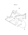
- each guide rail (48) is carried out in the following way (see Figure 10 ).
- the claw portion (51) of a guide rail (48) is either inserted in a clearance defined between the passage selecting member (36) and the bottom plate (3) or pierced into the bottom of the passage selecting member (36) for fixing one end of the guide rail (48) .
- the guide rail (48) is positioned on the bottom plate (3) so that the fixation hole (52) of the guide rail (48) and a screw hole or the like formed in the bottom plate (3) (not shown) are positioned one over the other.
- fixing means such as a screw is inserted through the hole (52) of the guide rail (48) for fixing the other end of the guide rail (48) to the bottom plate (3) .
- another guide rail (48) is prepared and its claw portion (51) is pierced into a longitudinal central portion of the main body portion (38) and fixed there. And, while bringing the guide rail (48) into contact with the first zoning member (28) and with the air-supply blower unit (17) so that the first zoning member (28) and the air-supply blower unit (17) are pressed forward by the guide rail (48) , the fixation portion (50) of the guide rail (48) is fixed to a front edge portion of the opening (16) in the left sideplate (6) . Further, still another guide rail (48) is prepared and its claw portion (51) is pierced into a rear portion of the main body portion (38) and fixed there.
- the fixation portion (50) of the guide rail (48) is fixed to a rear edge portion of the opening (16) in the left sideplate (6) .
- fixing means such as screw is used, like the guide rail (48) of the bottom plate (3) .
- the cable (55) formed by bundling an adequate number of cables (note that a cable for the damper motor (41) is not diagrammed) is fixed at several points with for example clamp members (57) and disposed so that when the heat exchanging element (15) is later inserted the cable (55) and the heat exchanging element (15) are prevented from interfering with each other.
- the cable (55) is introduced into the electric appliance box (54) and each cable is electrically wire-bound.
- the top plate (8) to which the guide rail (48) has been pre-attached or attached concurrently with the aforesaid work, is mounted on the front sideplate (4) , the rear sideplate (5) , the left sideplate (6) , and the right sideplate (7) .
- filters are inserted on the front sides of the air-supply passage and the air-exhaust passage of the heat exchanging element (15) from the opening (16) of the left sideplate (6) .
- the first outlet port (9) , the first inlet port (10) , the second outlet port (13) , and the second inlet port (14) are provided with the duct adapters (11, 12) .
- the metal hangers (56) are attached to the left sideplate (6) and to the right sideplate (7) .
- the air-supply blower unit (17) and the others are subjected to insulation test and withstand voltage test, and to running test.
- the inside of the unit casing (2) is cleaned.
- the opening (16) of the left sideplate (6) is closed with the openable/closable cover (58) (see Figure 10 or Figure 11 ).
- final examinations such as visual inspection are carried out and then packaging is performed after inspection acceptance.
- the assembly of the ventilating apparatus (1) can be carried out with ease and speed.
- the maintenance of the air-supply blower unit (17) and the others can be done easily by uncovering the cover of the opening (16) of the left sideplate (6) and removing the heat exchanging element (15) through the opening (16) along the guide rail (48) . That is, in accordance with the present embodiment, the maintenance of the ventilating apparatus (1) is also easy to carry out.
- the present invention is useful for ventilating apparatus.
Landscapes
- Engineering & Computer Science (AREA)
- Chemical & Material Sciences (AREA)
- Combustion & Propulsion (AREA)
- Mechanical Engineering (AREA)
- General Engineering & Computer Science (AREA)
- Air-Conditioning Room Units, And Self-Contained Units In General (AREA)
- Other Air-Conditioning Systems (AREA)
- Devices For Blowing Cold Air, Devices For Blowing Warm Air, And Means For Preventing Water Condensation In Air Conditioning Units (AREA)
- Ventilation (AREA)
- Cooling Or The Like Of Electrical Apparatus (AREA)
- Heat-Exchange Devices With Radiators And Conduit Assemblies (AREA)
- Air-Flow Control Members (AREA)
Abstract
Description
Claims (7)
- A ventilating apparatus comprising:a unit casing (2) in which a first inlet port (10) for the suction of air from the inside of a room, a first outlet port (9) for the discharge of air to said room inside, a second inlet port (14) for the suction of air from the outside of said room, and a second outlet port (13) for the discharge of air to said room outside are formed;a first zoning member (28), positioned in the vicinity of either one of said first inlet port (10) and said second outlet port (13), for dividing the inside of said unit casing (2) into an air-supply passage (30) through which outdoor air (102) is led indoors and an air-exhaust passage (31) through which indoor air (101) is led outdoors;a blower unit (18) for air-exhaust positioned in the vicinity of the other of said first inlet port (10) and said second outlet port (13);a second zoning member (29), positioned in the vicinity of either one of said second inlet port (14) and said first outlet port (9), for dividing the inside of said unit casing (2) into said air-supply passage (30) and said air-exhaust passage (31);a blower unit (17) for air-supply positioned in the vicinity of the other of said second inlet port (14) and said first outlet port (9);one or more heat exchanging elements (15), disposed between said first zoning member (28) and said air-exhaust blower unit (18) and between said second zoning member (29) and said air-supply blower unit (17), for effecting heat exchange between said outdoor air (102) of said air-supply passage (30) and said indoor air (101) of the air-exhaust passage (31); andone or more guide rails (48) for positioning and fixing said first zoning member (28), said second zoning member (29), said air-supply blower unit (17), and said air-exhaust blower unit (18), and for guiding said heat exchanging element (15) to a specified position in said unit casing (2).
- The ventilating apparatus of claim 1,
wherein an opening (16) for allowing said heat exchanging element (15) to be inserted along said guide rail (48) is formed in said unit casing (2). - The ventilating apparatus of claim 1,
wherein spacer members (26, 27) for securing spaces for the air suction or the air blowoff of said air-supply blower unit (17) and said air-exhaust blower unit (18) are mounted in said unit casing (2). - The ventilating apparatus of claim 1 further comprising:a passage selecting member (36) including a bypass passage (37) for allowing said indoor air (101) sucked from said fist inlet port (10) to bypass said heat exchanging element (15) and a damper (39) for selecting, as a passage for said indoor air (101), between a passage (32) passing through said heat exchanging element (15) and said bypass passage (37).
- A method of manufacturing a ventilating apparatus (1),
said ventilating apparatus (1) comprising:wherein in said ventilating apparatus manufacture method:a unit casing (2);zoning members (28, 29) for providing a division into an air-supply passage (30) and an air-exhaust passage (31) in said unit casing (2);blower units (17, 18) for leading outdoor air (102) indoors through said air-supply passage (30) and for leading indoor air (101) outdoors through said air-exhaust passage (31); anda heat exchanging element (15), positioned in said unit casing (2), for effecting heat exchange between said outdoor air (102) and said indoor air (101);attachment of said heat exchanging element (15) is carried out after said blower units (17, 18) and said zoning members (28, 29) are attached. - The ventilating apparatus manufacture method of claim 5,
wherein electrical wiring of said blower units (17, 18) is carried out prior to attachment of said heat exchanging element (15); and
wherein said heat exchanging element (15) is attached by inserting, after a guide rail (48) for guiding said heat exchanging element (15) during attachment and removal is mounted, said heat exchanging element (15) along said guide rail (48). - A method of manufacturing a ventilating apparatus (1).
said ventilating apparatus (1) comprising:wherein in said ventilating apparatus manufacture method:a unit casing (2) including: a bottom plate (3); a front sideplate (4) in which a first outlet port (9) for the discharge of air to the inside of a room and a first inlet port (10) for the suction of air from said room inside are formed side by side in a right-left direction; a rear sideplate (5) in which a second inlet port (14) for the suction of air from the outside of said room and a second outlet port (13) for the discharge of air to said room outside are formed side by side in a right-left direction; a left sideplate (6) in which an opening (16) is formed at the center thereof; a lid member (58) for closing said opening (16) in an openable and closable manner; a right sideplate (7); and a top plate (8);a blower unit (17) for air-supply so disposed in the vicinity of said first outlet port (9) that air is discharged from said first outlet port (9);a blower unit (18) for air-exhaust so disposed in the vicinity of said second outlet port (13) that air is discharged from said second outlet port (13);a first zoning member (28), disposed in the vicinity of said first inlet port (10), for dividing the inside of said unit casing (2) so that air sucked from said first inlet port (10) is led to said air-exhaust blower unit (18) while air sucked from said second inlet port (14) is led to said air-supply blower unit (17);a second zoning member (29), disposed in the vicinity of said second inlet port (14), for dividing the inside of said unit casing (2) so that air sucked from said second inlet port (14) is led to said air-supply blower unit (17) while air sucked from said first inlet port (10) is led to said air-exhaust blower unit (18);a first spacer member (26) interposed between said air-supply blower unit (17) and said left sideplate (6);a second spacer member (27) interposed between said air-exhaust blower unit (18) and said right sideplate (7);guide rails (48, 48) which are positioned at the longitudinal center of said bottom plate (3) of said unit casing (2) and at the longitudinal center of said top plate (8) of said unit casing (2), respectively and which each extend in a right-left direction ;a front guide rail (48) which is mounted on the rear of said air-supply blower unit (17) and said first zoning member (28) and which extends in a right-left direction;a rear guide rail (48) which is mounted on the front of said air-exhaust blower unit (18) and said second zoning member (29) and which extends in a right-left direction;a heat exchanging element (15), detachably mounted on each guide rail (48, 48) so as to be interposed between said air-supply blower unit (17) and said second zoning member (29) and between said air-exhaust blower unit (18) and said first zoning member (28), for effecting heat exchange between indoor air (101) sucked from said first inlet port (10) and outdoor air (102) sucked from said second inlet port (14);a passage selecting member (36) including a bypass passage (37) for allowing said indoor air (101) sucked from said fist inlet port (10) to bypass said heat exchanging element (15) and a damper (39) for selecting, as a passage for said indoor air (101), between a passage (32) passing through said heat exchanging element (15) and said bypass passage (37); andan electric appliance box (54) positioned outside said unit casing (2);said bottom plate (3), said front sideplate (4), said rear sideplate (5), said left sideplate (6), and said right sideplate (7) are assembled together;thereafter, said passage selecting member (36) is mounted;thereafter, said first spacer member (26) and said second spacer member (27) are mounted;thereafter, said air-supply blower unit (17) and said air-exhaust blower unit (18) are mounted;thereafter, said first zoning member (28) and said second zoning member (29) are mounted;thereafter, said guide rail (48) is attached to said bottom plate (3), while said front guide rail (48) and said rear guide rail (48) are mounted;thereafter, both said blower units (17, 18) and said electric appliance box (54) are connected together by a cable (55);thereafter, said heat exchanging element (15) is inserted from an opening (16) formed in said left sideplate (6) along each guide rail (48); andthereafter, said top plate (8) is attached.
Priority Applications (1)
| Application Number | Priority Date | Filing Date | Title |
|---|---|---|---|
| AT01917769T ATE344910T1 (en) | 2001-03-30 | 2001-03-30 | VENTILATION DEVICE AND METHOD FOR THE PRODUCTION THEREOF |
Applications Claiming Priority (1)
| Application Number | Priority Date | Filing Date | Title |
|---|---|---|---|
| PCT/JP2001/002839 WO2002081977A1 (en) | 2001-03-30 | 2001-03-30 | Ventilator and method of manufacturing the ventilator |
Publications (3)
| Publication Number | Publication Date |
|---|---|
| EP1376023A1 true EP1376023A1 (en) | 2004-01-02 |
| EP1376023A4 EP1376023A4 (en) | 2004-12-22 |
| EP1376023B1 EP1376023B1 (en) | 2006-11-08 |
Family
ID=11737215
Family Applications (1)
| Application Number | Title | Priority Date | Filing Date |
|---|---|---|---|
| EP01917769A Expired - Lifetime EP1376023B1 (en) | 2001-03-30 | 2001-03-30 | Ventilator and method of manufacturing the ventilator |
Country Status (7)
| Country | Link |
|---|---|
| EP (1) | EP1376023B1 (en) |
| JP (1) | JP4736305B2 (en) |
| CN (2) | CN1226570C (en) |
| DE (1) | DE60124428T8 (en) |
| ES (1) | ES2273817T3 (en) |
| TR (1) | TR200103426T1 (en) |
| WO (1) | WO2002081977A1 (en) |
Cited By (7)
| Publication number | Priority date | Publication date | Assignee | Title |
|---|---|---|---|---|
| EP1688675A2 (en) | 2005-02-07 | 2006-08-09 | Lg Electronics Inc. | Ventilating system |
| WO2007048383A3 (en) * | 2005-10-29 | 2007-09-07 | Brach & Moll Klimatechnik Gmbh | Air conditioner or cooling device |
| EP1832818A3 (en) * | 2006-03-06 | 2009-08-19 | STIEBEL ELTRON GmbH & Co. KG | Ventilation system |
| WO2017153801A1 (en) * | 2016-03-10 | 2017-09-14 | Carrier Corporation | Air handling unit |
| EP3370002A4 (en) * | 2015-10-29 | 2019-06-19 | Mitsubishi Electric Corporation | HEAT EXCHANGE VENTILATION DEVICE |
| US11035586B2 (en) | 2012-02-02 | 2021-06-15 | Carrier Corporation | Energy recovery ventilator |
| EP4148335A1 (en) * | 2021-09-14 | 2023-03-15 | Dantherm A/S | A heat recovery ventilation unit, an airstream swap unit and a pre-heater sub-assembly |
Families Citing this family (19)
| Publication number | Priority date | Publication date | Assignee | Title |
|---|---|---|---|---|
| EP1680627A1 (en) * | 2003-10-14 | 2006-07-19 | LG Electronics, Inc. | Ventilator |
| CN100434819C (en) * | 2004-06-09 | 2008-11-19 | 乐金电子(天津)电器有限公司 | Ventilator |
| KR101140705B1 (en) * | 2004-10-18 | 2012-05-03 | 삼성전자주식회사 | An ventilation apparatus |
| KR100628042B1 (en) * | 2005-02-15 | 2006-09-26 | 엘지전자 주식회사 | Ventilation system |
| JP4872428B2 (en) * | 2006-04-14 | 2012-02-08 | ダイキン工業株式会社 | Ventilation equipment |
| DE102009025651A1 (en) * | 2009-06-17 | 2011-01-05 | Meltem Lüftungsgeräte GmbH & Co. KG | Device for frost protection of a recuperative air exchange device and method for operating the device |
| KR101269287B1 (en) * | 2011-02-23 | 2013-05-29 | 이동욱 | Thermal energy collection ventilator |
| US9194603B2 (en) | 2011-08-10 | 2015-11-24 | Panasonic Ecology Systems Guangdong Co., Ltd. | Heating and ventilating fan |
| CN103375888B (en) * | 2012-04-27 | 2017-05-10 | 广东松下环境系统有限公司 | Heating ventilator |
| JP6509360B2 (en) * | 2015-10-29 | 2019-05-08 | 三菱電機株式会社 | Heat exchange ventilation system |
| KR101841953B1 (en) * | 2017-03-31 | 2018-03-26 | 탑에어주식회사 | Air blower having bypass function and heat exchanger having the same |
| US11287149B2 (en) * | 2017-06-08 | 2022-03-29 | Mitsubishi Electric Corporation | Heat exchange ventilator |
| WO2019058517A1 (en) * | 2017-09-22 | 2019-03-28 | 三菱電機株式会社 | Heat exchanging type ventilation system |
| CN109340987A (en) * | 2018-10-17 | 2019-02-15 | 张静 | Ventilation equipment |
| CN111189210A (en) * | 2019-12-31 | 2020-05-22 | 阿尔西制冷工程技术(北京)有限公司 | Heat recovery device and air conditioning system |
| CN111998453A (en) * | 2020-04-09 | 2020-11-27 | 卢利华 | Whole-house air epidemic prevention energy-saving system |
| KR20230026824A (en) * | 2021-08-18 | 2023-02-27 | 삼성전자주식회사 | Ventilation apparatus and ventilation system having the same |
| JP7507736B2 (en) * | 2021-10-27 | 2024-06-28 | 三菱電機株式会社 | Heat exchange ventilation system |
| JP7737040B2 (en) * | 2024-02-05 | 2025-09-10 | ダイキン工業株式会社 | ventilation equipment |
Family Cites Families (10)
| Publication number | Priority date | Publication date | Assignee | Title |
|---|---|---|---|---|
| DE3027447A1 (en) * | 1980-07-19 | 1982-02-11 | Horst Joachim 6700 Ludwigshafen Schmittel | Ventilation equipment for room - has additional heat exchanger in stale air current connected to heat exchanger inlet |
| JPS62218747A (en) * | 1986-03-19 | 1987-09-26 | Mitsubishi Electric Corp | Ceiling embedded type ventilator |
| JPS63190838A (en) * | 1987-02-04 | 1988-08-08 | Agency Of Ind Science & Technol | Production of ethylene glycol |
| JPH065543Y2 (en) * | 1987-05-18 | 1994-02-09 | 三菱電機株式会社 | Ventilation |
| JPH0641073Y2 (en) * | 1987-05-29 | 1994-10-26 | 三菱電機株式会社 | Ventilator with heat exchanger |
| JPH053833U (en) * | 1991-06-26 | 1993-01-22 | 株式会社東芝 | Exhaust fan with heat exchanger |
| JPH05223306A (en) * | 1992-02-17 | 1993-08-31 | Mitsubishi Electric Corp | Ventilator with heat exchanger |
| JPH0626684A (en) * | 1992-07-13 | 1994-02-04 | Matsushita Seiko Co Ltd | Electric part box of ventilator |
| JPH09137984A (en) * | 1995-11-14 | 1997-05-27 | Mitsubishi Electric Corp | Ventilation equipment |
| JP3114648B2 (en) * | 1997-04-30 | 2000-12-04 | ダイキン工業株式会社 | Motor unit mounting structure |
-
2001
- 2001-03-30 WO PCT/JP2001/002839 patent/WO2002081977A1/en not_active Ceased
- 2001-03-30 EP EP01917769A patent/EP1376023B1/en not_active Expired - Lifetime
- 2001-03-30 DE DE60124428T patent/DE60124428T8/en active Active
- 2001-03-30 CN CNB018003729A patent/CN1226570C/en not_active Expired - Lifetime
- 2001-03-30 ES ES01917769T patent/ES2273817T3/en not_active Expired - Lifetime
- 2001-03-30 TR TR2001/03426T patent/TR200103426T1/en unknown
- 2001-03-30 JP JP2002508884A patent/JP4736305B2/en not_active Expired - Lifetime
- 2001-10-26 CN CN01266869U patent/CN2531303Y/en not_active Expired - Lifetime
Cited By (12)
| Publication number | Priority date | Publication date | Assignee | Title |
|---|---|---|---|---|
| EP1688675A2 (en) | 2005-02-07 | 2006-08-09 | Lg Electronics Inc. | Ventilating system |
| EP1688675A3 (en) * | 2005-02-07 | 2007-12-19 | Lg Electronics Inc. | Ventilating system |
| US7331853B2 (en) | 2005-02-07 | 2008-02-19 | Lg Electronics Inc. | Ventilating system |
| CN1818491B (en) * | 2005-02-07 | 2010-10-06 | Lg电子株式会社 | Ventilating system |
| WO2007048383A3 (en) * | 2005-10-29 | 2007-09-07 | Brach & Moll Klimatechnik Gmbh | Air conditioner or cooling device |
| EP1832818A3 (en) * | 2006-03-06 | 2009-08-19 | STIEBEL ELTRON GmbH & Co. KG | Ventilation system |
| US11035586B2 (en) | 2012-02-02 | 2021-06-15 | Carrier Corporation | Energy recovery ventilator |
| EP3370002A4 (en) * | 2015-10-29 | 2019-06-19 | Mitsubishi Electric Corporation | HEAT EXCHANGE VENTILATION DEVICE |
| WO2017153801A1 (en) * | 2016-03-10 | 2017-09-14 | Carrier Corporation | Air handling unit |
| CN109154451A (en) * | 2016-03-10 | 2019-01-04 | 开利公司 | Air conditioner unit |
| US10890352B2 (en) | 2016-03-10 | 2021-01-12 | Carrier Corporation | Air handling unit |
| EP4148335A1 (en) * | 2021-09-14 | 2023-03-15 | Dantherm A/S | A heat recovery ventilation unit, an airstream swap unit and a pre-heater sub-assembly |
Also Published As
| Publication number | Publication date |
|---|---|
| JPWO2002081977A1 (en) | 2004-07-29 |
| CN2531303Y (en) | 2003-01-15 |
| CN1226570C (en) | 2005-11-09 |
| DE60124428T2 (en) | 2007-10-04 |
| JP4736305B2 (en) | 2011-07-27 |
| EP1376023A4 (en) | 2004-12-22 |
| ES2273817T3 (en) | 2007-05-16 |
| EP1376023B1 (en) | 2006-11-08 |
| WO2002081977A1 (en) | 2002-10-17 |
| DE60124428D1 (en) | 2006-12-21 |
| TR200103426T1 (en) | 2003-05-21 |
| DE60124428T8 (en) | 2008-01-17 |
| CN1406329A (en) | 2003-03-26 |
Similar Documents
| Publication | Publication Date | Title |
|---|---|---|
| EP1376023B1 (en) | Ventilator and method of manufacturing the ventilator | |
| AU2006209087B2 (en) | Indoor unit of air conditioner | |
| CN201615551U (en) | Vertical air conditioner | |
| CN101578488A (en) | Outdoor unit of air conditioner | |
| JP5449950B2 (en) | Outside air treatment air conditioner | |
| KR20090039797A (en) | Ventilation | |
| JP5449951B2 (en) | Outside air treatment air conditioner | |
| CN106765848B (en) | Integrated fresh air exchanging air conditioner | |
| EP1376022A1 (en) | Method of manufacturing ventilator | |
| JPH0626399A (en) | Thermoelectric supply device | |
| EP3370002B1 (en) | Heat exchanging ventilation device | |
| KR100964362B1 (en) | Air conditioner | |
| JPH0228342Y2 (en) | ||
| JP2005030734A (en) | Humidity control device | |
| JP4544419B2 (en) | Air conditioner | |
| CN223755501U (en) | air conditioner indoor unit | |
| JPH0641073Y2 (en) | Ventilator with heat exchanger | |
| JP2005030660A (en) | Air conditioner | |
| CN223596064U (en) | Indoor unit of air conditioner | |
| JP3443854B2 (en) | Air conditioner | |
| JP3744684B2 (en) | Air conditioning system | |
| JPH0330731Y2 (en) | ||
| JP2012154541A (en) | Air conditioner | |
| JPH063315Y2 (en) | Air conditioner for telephone box | |
| JPH06307670A (en) | Floor-standing ventilation unit for air conditioning |
Legal Events
| Date | Code | Title | Description |
|---|---|---|---|
| PUAI | Public reference made under article 153(3) epc to a published international application that has entered the european phase |
Free format text: ORIGINAL CODE: 0009012 |
|
| 17P | Request for examination filed |
Effective date: 20021106 |
|
| AK | Designated contracting states |
Kind code of ref document: A1 Designated state(s): AT BE CH CY DE DK ES FI FR GB GR IE IT LI LU MC NL PT SE TR |
|
| A4 | Supplementary search report drawn up and despatched |
Effective date: 20041105 |
|
| RIC1 | Information provided on ipc code assigned before grant |
Ipc: 7F 24F 12/00 B Ipc: 7F 24F 7/08 A Ipc: 7F 24F 13/20 B |
|
| GRAP | Despatch of communication of intention to grant a patent |
Free format text: ORIGINAL CODE: EPIDOSNIGR1 |
|
| GRAS | Grant fee paid |
Free format text: ORIGINAL CODE: EPIDOSNIGR3 |
|
| GRAA | (expected) grant |
Free format text: ORIGINAL CODE: 0009210 |
|
| AK | Designated contracting states |
Kind code of ref document: B1 Designated state(s): AT BE CH CY DE DK ES FI FR GB GR IE IT LI LU MC NL PT SE TR |
|
| PG25 | Lapsed in a contracting state [announced via postgrant information from national office to epo] |
Ref country code: IT Free format text: LAPSE BECAUSE OF FAILURE TO SUBMIT A TRANSLATION OF THE DESCRIPTION OR TO PAY THE FEE WITHIN THE PRESCRIBED TIME-LIMIT;WARNING: LAPSES OF ITALIAN PATENTS WITH EFFECTIVE DATE BEFORE 2007 MAY HAVE OCCURRED AT ANY TIME BEFORE 2007. THE CORRECT EFFECTIVE DATE MAY BE DIFFERENT FROM THE ONE RECORDED. Effective date: 20061108 Ref country code: CH Free format text: LAPSE BECAUSE OF FAILURE TO SUBMIT A TRANSLATION OF THE DESCRIPTION OR TO PAY THE FEE WITHIN THE PRESCRIBED TIME-LIMIT Effective date: 20061108 Ref country code: FI Free format text: LAPSE BECAUSE OF FAILURE TO SUBMIT A TRANSLATION OF THE DESCRIPTION OR TO PAY THE FEE WITHIN THE PRESCRIBED TIME-LIMIT Effective date: 20061108 Ref country code: NL Free format text: LAPSE BECAUSE OF FAILURE TO SUBMIT A TRANSLATION OF THE DESCRIPTION OR TO PAY THE FEE WITHIN THE PRESCRIBED TIME-LIMIT Effective date: 20061108 Ref country code: LI Free format text: LAPSE BECAUSE OF FAILURE TO SUBMIT A TRANSLATION OF THE DESCRIPTION OR TO PAY THE FEE WITHIN THE PRESCRIBED TIME-LIMIT Effective date: 20061108 Ref country code: AT Free format text: LAPSE BECAUSE OF FAILURE TO SUBMIT A TRANSLATION OF THE DESCRIPTION OR TO PAY THE FEE WITHIN THE PRESCRIBED TIME-LIMIT Effective date: 20061108 |
|
| REG | Reference to a national code |
Ref country code: GB Ref legal event code: FG4D |
|
| REG | Reference to a national code |
Ref country code: CH Ref legal event code: EP |
|
| REG | Reference to a national code |
Ref country code: IE Ref legal event code: FG4D |
|
| REF | Corresponds to: |
Ref document number: 60124428 Country of ref document: DE Date of ref document: 20061221 Kind code of ref document: P |
|
| PG25 | Lapsed in a contracting state [announced via postgrant information from national office to epo] |
Ref country code: DK Free format text: LAPSE BECAUSE OF FAILURE TO SUBMIT A TRANSLATION OF THE DESCRIPTION OR TO PAY THE FEE WITHIN THE PRESCRIBED TIME-LIMIT Effective date: 20070208 Ref country code: SE Free format text: LAPSE BECAUSE OF FAILURE TO SUBMIT A TRANSLATION OF THE DESCRIPTION OR TO PAY THE FEE WITHIN THE PRESCRIBED TIME-LIMIT Effective date: 20070208 |
|
| PG25 | Lapsed in a contracting state [announced via postgrant information from national office to epo] |
Ref country code: PT Free format text: LAPSE BECAUSE OF FAILURE TO SUBMIT A TRANSLATION OF THE DESCRIPTION OR TO PAY THE FEE WITHIN THE PRESCRIBED TIME-LIMIT Effective date: 20070409 |
|
| ET | Fr: translation filed | ||
| NLV1 | Nl: lapsed or annulled due to failure to fulfill the requirements of art. 29p and 29m of the patents act | ||
| REG | Reference to a national code |
Ref country code: ES Ref legal event code: FG2A Ref document number: 2273817 Country of ref document: ES Kind code of ref document: T3 |
|
| REG | Reference to a national code |
Ref country code: CH Ref legal event code: PL |
|
| PLBE | No opposition filed within time limit |
Free format text: ORIGINAL CODE: 0009261 |
|
| STAA | Information on the status of an ep patent application or granted ep patent |
Free format text: STATUS: NO OPPOSITION FILED WITHIN TIME LIMIT |
|
| 26N | No opposition filed |
Effective date: 20070809 |
|
| PG25 | Lapsed in a contracting state [announced via postgrant information from national office to epo] |
Ref country code: MC Free format text: LAPSE BECAUSE OF NON-PAYMENT OF DUE FEES Effective date: 20070331 Ref country code: IE Free format text: LAPSE BECAUSE OF NON-PAYMENT OF DUE FEES Effective date: 20070330 |
|
| PG25 | Lapsed in a contracting state [announced via postgrant information from national office to epo] |
Ref country code: GR Free format text: LAPSE BECAUSE OF FAILURE TO SUBMIT A TRANSLATION OF THE DESCRIPTION OR TO PAY THE FEE WITHIN THE PRESCRIBED TIME-LIMIT Effective date: 20070209 |
|
| PG25 | Lapsed in a contracting state [announced via postgrant information from national office to epo] |
Ref country code: LU Free format text: LAPSE BECAUSE OF NON-PAYMENT OF DUE FEES Effective date: 20070330 Ref country code: CY Free format text: LAPSE BECAUSE OF FAILURE TO SUBMIT A TRANSLATION OF THE DESCRIPTION OR TO PAY THE FEE WITHIN THE PRESCRIBED TIME-LIMIT Effective date: 20061108 |
|
| PG25 | Lapsed in a contracting state [announced via postgrant information from national office to epo] |
Ref country code: TR Free format text: LAPSE BECAUSE OF FAILURE TO SUBMIT A TRANSLATION OF THE DESCRIPTION OR TO PAY THE FEE WITHIN THE PRESCRIBED TIME-LIMIT Effective date: 20061108 |
|
| REG | Reference to a national code |
Ref country code: FR Ref legal event code: PLFP Year of fee payment: 16 |
|
| REG | Reference to a national code |
Ref country code: FR Ref legal event code: PLFP Year of fee payment: 17 |
|
| REG | Reference to a national code |
Ref country code: FR Ref legal event code: PLFP Year of fee payment: 18 |
|
| PGFP | Annual fee paid to national office [announced via postgrant information from national office to epo] |
Ref country code: DE Payment date: 20200317 Year of fee payment: 20 Ref country code: IT Payment date: 20200221 Year of fee payment: 20 Ref country code: GB Payment date: 20200318 Year of fee payment: 20 |
|
| PGFP | Annual fee paid to national office [announced via postgrant information from national office to epo] |
Ref country code: BE Payment date: 20200217 Year of fee payment: 20 |
|
| PGFP | Annual fee paid to national office [announced via postgrant information from national office to epo] |
Ref country code: FR Payment date: 20200214 Year of fee payment: 20 |
|
| PGFP | Annual fee paid to national office [announced via postgrant information from national office to epo] |
Ref country code: ES Payment date: 20200401 Year of fee payment: 20 |
|
| REG | Reference to a national code |
Ref country code: DE Ref legal event code: R071 Ref document number: 60124428 Country of ref document: DE |
|
| REG | Reference to a national code |
Ref country code: GB Ref legal event code: PE20 Expiry date: 20210329 |
|
| PG25 | Lapsed in a contracting state [announced via postgrant information from national office to epo] |
Ref country code: GB Free format text: LAPSE BECAUSE OF EXPIRATION OF PROTECTION Effective date: 20210329 |
|
| REG | Reference to a national code |
Ref country code: BE Ref legal event code: MK Effective date: 20210330 |
|
| REG | Reference to a national code |
Ref country code: ES Ref legal event code: FD2A Effective date: 20211229 |
|
| PG25 | Lapsed in a contracting state [announced via postgrant information from national office to epo] |
Ref country code: ES Free format text: LAPSE BECAUSE OF EXPIRATION OF PROTECTION Effective date: 20210331 |