EP1376014A2 - Heating stove type fireplace - Google Patents
Heating stove type fireplace Download PDFInfo
- Publication number
- EP1376014A2 EP1376014A2 EP03396058A EP03396058A EP1376014A2 EP 1376014 A2 EP1376014 A2 EP 1376014A2 EP 03396058 A EP03396058 A EP 03396058A EP 03396058 A EP03396058 A EP 03396058A EP 1376014 A2 EP1376014 A2 EP 1376014A2
- Authority
- EP
- European Patent Office
- Prior art keywords
- fireplace
- heat
- heat storage
- storage unit
- gases
- Prior art date
- Legal status (The legal status is an assumption and is not a legal conclusion. Google has not performed a legal analysis and makes no representation as to the accuracy of the status listed.)
- Granted
Links
Images


Classifications
-
- F—MECHANICAL ENGINEERING; LIGHTING; HEATING; WEAPONS; BLASTING
- F24—HEATING; RANGES; VENTILATING
- F24B—DOMESTIC STOVES OR RANGES FOR SOLID FUELS; IMPLEMENTS FOR USE IN CONNECTION WITH STOVES OR RANGES
- F24B1/00—Stoves or ranges
- F24B1/20—Ranges
- F24B1/24—Ranges with built-in masses for heat storage or heat insulation
-
- F—MECHANICAL ENGINEERING; LIGHTING; HEATING; WEAPONS; BLASTING
- F24—HEATING; RANGES; VENTILATING
- F24B—DOMESTIC STOVES OR RANGES FOR SOLID FUELS; IMPLEMENTS FOR USE IN CONNECTION WITH STOVES OR RANGES
- F24B1/00—Stoves or ranges
- F24B1/18—Stoves with open fires, e.g. fireplaces
Definitions
- the invention relates to a heating stove type fireplace according to the introduction of claim 1.
- Heating stoves are traditionally fireplaces intended for quick heating.
- the heating stove contains a metal shell surrounding the furnace that extends upward to form a channel for rising smoke and a chimney connection, through which smoke gases are guided into the smoke chimney. Because the heating stove releases the heat it creates for all practical purposes immediately through its metal shell to the surrounding airspace, it is quick-heating if wood is burned in it efficiently and cleanly.
- the object of the invention is to remove the above-mentioned disadvantages.
- the object of the invention is to provide a novel heating stove type fireplace that would further make possible traditional quick heating, but would also make possible the effective use of the energy contained in wood and clean burning without unclean burn gases.
- a heating stove fireplace for heating a living space contains a metal shell surrounding a furnace with an openable hatch and a grate.
- a heat storage unit of a material that can well withstand the stress of high temperatures and that quickly stores heat.
- a burn gases afterglow heat transfer unit to effect direct transfer of heat from burn gases that come from the heat storage unit and still contain heat energy to the airspace surrounding the fireplace.
- the fireplace has a chimney connection for smoke gases after the afterglow heat transfer unit.
- the basis of this invention is that effective and clean burning requires a relatively fast and high-temperature burn process.
- this burn process can usefully be joined with a heating stove type fireplace, the heat energy of the hottest burn gases must be stored immediately, before the heat of the heating stove is transferred to the outer shell. From this was born the basic idea of the invention, i.e. the locating of a heat storage unit within a traditional heating stove in-between the furnace and the metal shell of the heating stove that releases heat outward into the area of the room.
- the fireplace releases the heat of partially cooled burn gases through the metal shell in the manner of a traditional heating stove while at the same time, during the heating phase, storing the greater part of the heat in a heat storage unit.
- the heat storage unit begins to release heat through the metal shell and the other structures of the fireplace.
- the heating stove according to the invention works thus not only in the manner of a traditional heating stove as a quick heater, but also as a long-term source of heat that releases heat slowly while also making possible very low emission and clean smoke gases that have largely released their heat.
- the heat transfer unit for burn gases afterglow consists of a part of the metal shell whose inner surface is in direct contact with the smoke gases coming from the heat storage unit.
- the outer shell of the fireplace is tight-fitting and without openings in the area of the afterglow heat transfer unit as well as after it in the flow direction of smoke gases.
- the furnace is made of heat-storing materials such as soapstone that form the rear wall, side walls and also the cover structure of the throat leading towards the heat storage unit.
- heat-storing structures work, in addition to the main heat unit located after the furnace, as structures that rapidly store heat energy. This makes possible a burning event in the furnace with cleaner smoke gases that occurs at a higher temperature and is more effective than previously possible without having the temperature of the outer shell of the heating stove rise to dangerous levels.
- the chimney connection of the heating stove is above the afterglow heat transfer unit.
- the heating stove is relatively small in both depth and width.
- the furnace, heat storage unit, afterglow heat transfer unit and chimney connection are partially or completely located in relationship to each other adjacent, stacked on top of one another, or fit in some other way as will be apparent later in this description.
- the metal outer shell for example a surface shell of heat-storing material.
- the metal shell can be covered completely, for example with tiles or soapstone or some other type of stone tile that possesses a desired colour and appearance.
- the afterglow heat transfer unit performing preferably direct and fast heat transfer of the smoke gases, is located inside the surface shell so that one can use flow openings in the surface shell to create airflow from the heat transfer unit to the airspace surrounding the fireplace.
- the heat storage unit located after the furnace consists of a huge heat-storing mass, such as a soapstone structure, through which are arrayed a plurality of rising and/or transverse smoke channels to increase heat transfer surface area between the hot smoke gases and the mass.
- the heat-storing mass can also be of sealing compound or of many parts composing one mass.
- the mass must essentially have a relatively large heat transfer surface area, i.e. the sum of the surface areas of the gas channels travelling through and around the mass. This enables effective and fast heat transfer to the heat-storing material from very hot, perhaps partially still burning smoke gases.
- the heat-storing mass it consists of many one-directional and preferably vertical plates slightly distant from one another and of a heat-storing material.
- the distances between the plates form smoke channels.
- the plates can be for example soapstone plates of uniform thickness where plate thickness is about double the width of the distance between individual plates. In this way 5-10 plates can be fit into the heating stove creating a large, effectively heat-absorbing surface.
- the plates can be used flow distributors, for example plate-like guides of metal or soapstone.
- flow distributors for example plate-like guides of metal or soapstone.
- the entire volume of the heat storage unit functions at essentially the same temperature and at maximum power to store an integral part of the heat energy of the hot smoke gases and to release out to the metal shell of the heating stove a flow of warm, i.e. not too hot, gases.
- both the heat storage and heat release features of the heat storage unit can be adjusted.
- the soapstone plates of the mass can be attached on all sides to the surrounding metal shell, wherein the smoke channels traverse only within the heat-storing mass. Heat is thus effectively stored into the heat storage unit, while the outer surface of the fireplace in the area of the heat storage unit stays relatively cool during heating. This way heat flow in the surrounding area during heating occurs through the smoke gases afterglow heat transfer unit.
- the metal shell extends in a vertical direction up the fireplace from the bottom part level of the furnace up to the chimney connection. This way the metal shell can function as the load-bearing structure of the fireplace and as its outer shell. It is also possible that the metal shell is vertical only in the area of the heat storage unit and from there outward forming the afterglow heat transfer unit. It is even possible that the metal shell rests on and seals only in the upper part of the heat storage unit and continues from there upward, wherein the outer surface of the furnace area and the greater part of the outer surface of the heat storage unit area can be for example the same soapstone structure that forms the furnace and heat storage unit.
- brackets, props, or other supports in the metal shell from the lower edge of the fireplace upwards over essentially its entire height can be used to provide support for the entire massive heat-storing inner part of the fireplace. This way the weight of the heat storage unit does not lie on the structures of the fireplace, making possible the tearing out and rebuilding, i.e. the exchanging, if needed, of the heat-storing wall structures of the furnace without disturbing the upper structures of the fireplace.
- a heating stove type fireplace according to the invention is of modular structure, i.e. it is composed of three suitably measured modules separately distinguished by measurement of their desired heating characteristics and located on top of one another and/or adjacent, the furnace module, the heat storage module, the heat transfer module.
- the modules are separately attachable to one another, making possible modules of different size and shape.
- the number of modules is also variable, because multiple heat storage heat storage modules as well as possibly multiple heat transfer modules can be arranged one after the other and/or one on top of the other.
- the thickness of the heat-storing mass of the furnace walls i.e. their heating capacity, the height of the furnace as well as the form of the hatch or the size of its opening can all vary.
- the shape and number of the smoke channels the amount of heat-storing mass and the amount of usable heat-storing mass can all vary, as well as height/width/depth of the entire heat storage unit. The adjustment of height/width/depth is preferably achieved by having the heat storage unit be composed of two or more stacked or adjacent cheaply identical heat storage modules.
- a suitable heat transfer unit can be chosen to follow it. It may be relatively low and have a conical reduction of the furnace towards the chimney connection, or it may have more height and therefore more also a greater heat transfer surface area. It can also be larger and wider than the heat storage module located before it.
- the inner surface of the heat transfer module which is in contact with the smoke gases, can also have heat transfer fins used to increase heat absorption. In the same way its outer surface can have convex shape that for example form decorations, but also increase exterior surface area for heat release.
- a control is arranged in the fireplace that enables bypass of the heat storage unit for a short time, for example when it is desired to quickly get heat into a room area.
- the control is used to guide hot burn gases directly to the afterglow heat transfer unit.
- the fireplace can even have, in conjunction with the control, a separate express heater, i.e. a heat-conducting shell before the afterglow heat transfer unit such that direct heat transfer surface area into the area of the room is noticeably greater than during normal heating.
- a heating stove type fireplace according to the invention has significant advantages compared to known prior art. Since there is often a need to get quick heat, the heating stove has its own application area. In addition, its small size and relative lightness are often are often critical factors when purchasing a heating device. A fireplace according to the invention has managed to retain all the aforementioned positive attributes of the traditional heating stove. In addition, an attempt has been made to add new heating technologies and effective heat storage capacity such as to create a wholeness where, with less amount of fuel and cleaner smoke gases, better heating characteristics are achieved for both quick heat production and long-term and even heat release.
- This invention makes possible the burning of wood and briquettes at a temperature of 800°C or more, preferably at a temperature of approximately 1000°C. Using these structures and methods the energy use relationship of the fireplace is increased 10-30%, even 50%, compared to traditional heating stoves.
- the heating stove type fireplace in figure 1 contains a metal outer shell 1, which extends from the very bottom edge of the fireplace upward for the entire height of the fireplace.
- the fireplace has a furnace 4 with a hatch (not illustrated) and a grate 3 and that opens upward through the throat to the heat storage unit 5.
- the metal outer shell 1 narrows greatly forming a tapering surface towards the upward-pointing chimney connection, which forms the smoke gases afterglow heat transfer unit 6.
- the inside of the metal shell of the heat transfer unit 6 is in direct contact with the still relatively warm smoke gases rising from the heat storage unit and on the outside it is in direct contact with the airspace 7 to be heated. Therefore, heat energy is allowed to rapidly and effectively move through the metal shell 6 and a relatively well-cooled flow of smoke gases rises to the chimney connection 8.
- the fireplace in figure 1 can be of modular structure such that the modules are separate from one another and thus combinative and stackable one on top of the other in a suitable combination.
- the furnace module 17 is of course at the bottom.
- On top of this are stacked three identical heat storage modules 18, on top of which is located the heat transfer module 19.
- figure 1 also shows supports 20 attached to the outer shell 1, on which the heat storage modules 18, i.e. the upper massive parts of the fireplace above the furnace, rests so that the furnace wall structures can be changed or maintained without dismantling the entire heating stove.
- the heat storage modules 18, i.e. the upper massive parts of the fireplace above the furnace rests so that the furnace wall structures can be changed or maintained without dismantling the entire heating stove.
- the furnace 4 consists of a rear wall 9 and side walls 10 of heat-storing soapstone, as well as cover structure 11 of the furnace, also of soapstone, load-bearing blocks, which form the throat towards the heat storage unit 5.
- heat storage unit 5 In heat storage unit 5 are six upright, adjacent plates 15, each of which is composed of six soapstone plates.
- the plates 15 are one-directional and suitably distant from one another such, that the area between the plates forms vertically-leading smoke channels 14.
- metal flow distributors 16 i.e. guides for the upward-rising flow of smoke gases. Through these the hot, rising smoke gases are guided as evenly as possible across the entire surface area of the plates 15, such that the storage of heat into the soapstone plates is effective.
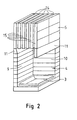
- Figure 3 shows another embodiment of this invention, in which the furnace 4 and the heat storage unit 5 located above it are like those in the embodiment of figure 1.
- the metal outer shell 2 begins only above the furnace, i.e. from the lower edge of the heat storage unit 5. It is also possible that it begins only from near the upper edge of the heat storage unit.
- the fireplace in the embodiment of this figure is further surrounded by a surface shell 12 of preferably soapstone.
- the surface shell forms preferably a front wall, rear wall, side walls and cover for the fireplace.
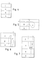
- Figures 4-7 show by way of example different structural alternatives of how the different parts of a fireplace according to the invention can be located in relationship to one another. There are of course even more possible alternatives.
Landscapes
- Engineering & Computer Science (AREA)
- Chemical & Material Sciences (AREA)
- Combustion & Propulsion (AREA)
- Mechanical Engineering (AREA)
- General Engineering & Computer Science (AREA)
- Solid-Fuel Combustion (AREA)
- Incineration Of Waste (AREA)
- Tunnel Furnaces (AREA)
- Crystals, And After-Treatments Of Crystals (AREA)
- Resistance Heating (AREA)
Abstract
Description
Claims (17)
- A heating stove type fireplace used for heating living spaces, characterized in that the fireplace containsa metal outer shell (1,2),a furnace (4) provided with an openable hatch and grate (3),a heat storage unit (5) located after the furnace in the flow direction of essentially hottest burn gases,a smoke gases afterglow heat transfer unit (6) located after the heat storage unit in the flow direction of burn gases to effect direct heat transfer to the surrounding airspace from smoke gases coming from the heat storage unit (7) as well asa smoke gases chimney connection (8) located after the afterglow heat transfer unit.
- A fireplace according to claim 1, characterized in that the smoke gases afterglow heat transfer unit (6) is comprised of a part of the metal outer shell (1,2), whose inner surface is in direct contact with smoke gases coming from the heat storage unit (5).
- A fireplace according to claim 1 or 2, characterized in that the furnace (4) is comprised of a rear wall (9), side walls (10), as well as a cover structure (11) forming a throat towards the heat storage unit (5) of heat-storing material, preferably of soapstone.
- A fireplace according to any of claims 1 to 3, characterized in that the grate (3) has a pre-burn control, which enables effective burning, for guiding burn air adjustably and optionally from the different areas of the grate through it to the burning load.
- A fireplace according to any of claims 1 to 4, characterized in that the fireplace has a tight-fitting outer shell having no openings in the area of the afterglow heat transfer unit and after it in the flow direction of smoke gases.
- A fireplace according to any of claims 1 to 5, characterized in that outside the metal outer shell (2) is a surface shell (12).
- A fireplace according to claim 6, characterized in that the heat transfer unit (6) is inside the surface shell (12), wherein the surface shell contains flow openings (13) to effect airflow from the heat transfer unit to the airspace (7) surrounding the fireplace.
- A fireplace according to any of claims 1 to 7, characterized in that the heat storage unit (5) consists of a massive heat-storing mass, such as of soapstone, through which are arrayed a plurality of smoke channels (14) to increase surface area for heat transfer between the smoke gases and the mass.
- A fireplace according to claim 8, characterized in that the heat-storing mass consists of a plurality of one-directional plates (15) slightly distant from one another, where the distances between plates form the smoke channels (14).
- A fireplace according to claim 9, characterized in that the smoke channels (14) between the plates (15) have flow distributors (16) that spread the hot smoke gases essentially evenly over the entire surface area of the plates.
- A fireplace according to any of claims 1 to 10, characterized in that the metal shell (1) extends in the flow direction of burn gases from below the furnace (4) to the chimney connection.
- A fireplace according to any of claims 1 to 10, characterized in that the metal shell (2) extends in the flow direction of burn gases from the area of the heat storage unit (5) to the chimney connection (8).
- A fireplace according to any of claims 1 to 11, characterized in that the metal shell (1) has supports for support of the heat-storing inner area of the fireplace above the furnace (4).
- A fireplace according to any of claims 1 to 13, characterized in that the fireplace is composed of three stacked and/or adjacent modules separately distinguished by measurement of their desired heating characteristics, the furnace module (17), heat storage module (18) and the heat transfer module (19).
- A fireplace according claim 14, characterized in that the heat storage unit is comprised of two or more stacked and/or adjacent, preferably identical, heat storage modules.
- A fireplace according to any of claims 1 to 15, characterized in that the fireplace has a control (R) to guide hot burn gases optionally through the heat storage unit (5) or past the heat storage unit to the afterglow heat transfer unit (6).
- A fireplace according to any of claims 1 to 15, characterized in that the fireplace has a express heat releaser (Q) to guide hot burn gases essentially directly to the airspace surrounding the fireplace.
Applications Claiming Priority (2)
| Application Number | Priority Date | Filing Date | Title |
|---|---|---|---|
| FI20021205A FI20021205A0 (en) | 2002-06-20 | 2002-06-20 | Hearth |
| FI20021205 | 2002-06-20 |
Publications (3)
| Publication Number | Publication Date |
|---|---|
| EP1376014A2 true EP1376014A2 (en) | 2004-01-02 |
| EP1376014A3 EP1376014A3 (en) | 2006-11-22 |
| EP1376014B1 EP1376014B1 (en) | 2009-07-29 |
Family
ID=8564197
Family Applications (1)
| Application Number | Title | Priority Date | Filing Date |
|---|---|---|---|
| EP03396058A Expired - Lifetime EP1376014B1 (en) | 2002-06-20 | 2003-06-16 | Heating stove type fireplace |
Country Status (4)
| Country | Link |
|---|---|
| EP (1) | EP1376014B1 (en) |
| AT (1) | ATE438067T1 (en) |
| DE (1) | DE60328563D1 (en) |
| FI (1) | FI20021205A0 (en) |
Cited By (3)
| Publication number | Priority date | Publication date | Assignee | Title |
|---|---|---|---|---|
| EP2267370A1 (en) * | 2009-06-23 | 2010-12-29 | Peter Kobler | Combustion oven |
| EP2330352A1 (en) * | 2009-12-02 | 2011-06-08 | Nunnanlahden Uuni Oy | Fireplace |
| EP2345848A1 (en) * | 2010-01-15 | 2011-07-20 | Tulikivi Oyj | Arrangement in heat-accumulating fireplace |
Families Citing this family (1)
| Publication number | Priority date | Publication date | Assignee | Title |
|---|---|---|---|---|
| RU2473842C1 (en) * | 2011-08-25 | 2013-01-27 | Владимир Иванович Коштаков | Method for bricklaying of furnaces and fireplaces |
Family Cites Families (3)
| Publication number | Priority date | Publication date | Assignee | Title |
|---|---|---|---|---|
| FR2528951B1 (en) * | 1982-06-22 | 1987-02-20 | Gravier Maurice | DEVICE FOR RECOVERING CALORIES FROM A FIREPLACE AND METHOD FOR THE PRODUCTION THEREOF |
| CH647856A5 (en) * | 1982-09-30 | 1985-02-15 | Hans Peter Fryand | Device for accumulating heat, in particular in a fireplace or fireplace furnace |
| DE8716439U1 (en) * | 1987-12-12 | 1988-05-26 | Champ Sauna Sonne Freizeit Vertriebsgesellschaft mbH, 3589 Knüllwald | Circulating air tiled stove with heat storage |
-
2002
- 2002-06-20 FI FI20021205A patent/FI20021205A0/en unknown
-
2003
- 2003-06-16 AT AT03396058T patent/ATE438067T1/en not_active IP Right Cessation
- 2003-06-16 EP EP03396058A patent/EP1376014B1/en not_active Expired - Lifetime
- 2003-06-16 DE DE60328563T patent/DE60328563D1/en not_active Expired - Fee Related
Cited By (4)
| Publication number | Priority date | Publication date | Assignee | Title |
|---|---|---|---|---|
| EP2267370A1 (en) * | 2009-06-23 | 2010-12-29 | Peter Kobler | Combustion oven |
| EP2330352A1 (en) * | 2009-12-02 | 2011-06-08 | Nunnanlahden Uuni Oy | Fireplace |
| RU2547853C2 (en) * | 2009-12-02 | 2015-04-10 | Нуннанлахден Ууни Ой | Fire-place |
| EP2345848A1 (en) * | 2010-01-15 | 2011-07-20 | Tulikivi Oyj | Arrangement in heat-accumulating fireplace |
Also Published As
| Publication number | Publication date |
|---|---|
| EP1376014A3 (en) | 2006-11-22 |
| DE60328563D1 (en) | 2009-09-10 |
| ATE438067T1 (en) | 2009-08-15 |
| FI20021205A0 (en) | 2002-06-20 |
| EP1376014B1 (en) | 2009-07-29 |
Similar Documents
| Publication | Publication Date | Title |
|---|---|---|
| EP2107315A2 (en) | Fireplace | |
| RU153204U1 (en) | HEATING BOILER | |
| US10627112B2 (en) | Combustion apparatus | |
| US4292933A (en) | Furnace | |
| US4561420A (en) | Woodburning stove, fireplace or the like | |
| EP1376014B1 (en) | Heating stove type fireplace | |
| RU70966U1 (en) | MULTIFUNCTIONAL FURNACE | |
| DE3614998C2 (en) | ||
| US4597376A (en) | Heat recovery hood | |
| EP1890092B1 (en) | Fire place for solid fuel for the heating of a room and remote rooms as for heating of sanitary water. | |
| US20080035137A1 (en) | Combustion apparatus | |
| RU2551183C2 (en) | Heating device | |
| KR101622270B1 (en) | a portable korean underfloor heating boiler | |
| RU2610411C2 (en) | Heating device | |
| RU2445550C1 (en) | Heating device | |
| CN205048482U (en) | Cooking heating stove | |
| RU61012U1 (en) | HEATING DEVICE | |
| GB2233748A (en) | Improvements in or relating to back boilers | |
| FI105948B (en) | Accumulating fireplace | |
| GB2541452B (en) | An oven | |
| RU146582U1 (en) | BOILER HEATING WATER HEATING | |
| RU72747U1 (en) | FURNACE UNIVERSAL | |
| RU2337274C2 (en) | Heating device | |
| RU101154U1 (en) | HEATING DEVICE | |
| RU139286U1 (en) | HEATING COMBINED FURNACE |
Legal Events
| Date | Code | Title | Description |
|---|---|---|---|
| PUAI | Public reference made under article 153(3) epc to a published international application that has entered the european phase |
Free format text: ORIGINAL CODE: 0009012 |
|
| AK | Designated contracting states |
Kind code of ref document: A2 Designated state(s): AT BE BG CH CY CZ DE DK EE ES FI FR GB GR HU IE IT LI LU MC NL PT RO SE SI SK TR |
|
| AX | Request for extension of the european patent |
Extension state: AL LT LV MK |
|
| PUAL | Search report despatched |
Free format text: ORIGINAL CODE: 0009013 |
|
| AK | Designated contracting states |
Kind code of ref document: A3 Designated state(s): AT BE BG CH CY CZ DE DK EE ES FI FR GB GR HU IE IT LI LU MC NL PT RO SE SI SK TR |
|
| AX | Request for extension of the european patent |
Extension state: AL LT LV MK |
|
| 17P | Request for examination filed |
Effective date: 20070512 |
|
| AKX | Designation fees paid |
Designated state(s): AT BE BG CH CY CZ DE DK EE ES FI FR GB GR HU IE IT LI LU MC NL PT RO SE SI SK TR |
|
| RAP1 | Party data changed (applicant data changed or rights of an application transferred) |
Owner name: NUNNAUUNI OY |
|
| 17Q | First examination report despatched |
Effective date: 20080327 |
|
| GRAP | Despatch of communication of intention to grant a patent |
Free format text: ORIGINAL CODE: EPIDOSNIGR1 |
|
| GRAS | Grant fee paid |
Free format text: ORIGINAL CODE: EPIDOSNIGR3 |
|
| GRAA | (expected) grant |
Free format text: ORIGINAL CODE: 0009210 |
|
| AK | Designated contracting states |
Kind code of ref document: B1 Designated state(s): AT BE BG CH CY CZ DE DK EE ES FI FR GB GR HU IE IT LI LU MC NL PT RO SE SI SK TR |
|
| REG | Reference to a national code |
Ref country code: GB Ref legal event code: FG4D |
|
| REG | Reference to a national code |
Ref country code: CH Ref legal event code: EP |
|
| REG | Reference to a national code |
Ref country code: IE Ref legal event code: FG4D |
|
| REF | Corresponds to: |
Ref document number: 60328563 Country of ref document: DE Date of ref document: 20090910 Kind code of ref document: P |
|
| NLV1 | Nl: lapsed or annulled due to failure to fulfill the requirements of art. 29p and 29m of the patents act | ||
| PG25 | Lapsed in a contracting state [announced via postgrant information from national office to epo] |
Ref country code: AT Free format text: LAPSE BECAUSE OF FAILURE TO SUBMIT A TRANSLATION OF THE DESCRIPTION OR TO PAY THE FEE WITHIN THE PRESCRIBED TIME-LIMIT Effective date: 20090729 Ref country code: ES Free format text: LAPSE BECAUSE OF FAILURE TO SUBMIT A TRANSLATION OF THE DESCRIPTION OR TO PAY THE FEE WITHIN THE PRESCRIBED TIME-LIMIT Effective date: 20091109 Ref country code: SE Free format text: LAPSE BECAUSE OF FAILURE TO SUBMIT A TRANSLATION OF THE DESCRIPTION OR TO PAY THE FEE WITHIN THE PRESCRIBED TIME-LIMIT Effective date: 20090729 |
|
| PG25 | Lapsed in a contracting state [announced via postgrant information from national office to epo] |
Ref country code: SI Free format text: LAPSE BECAUSE OF FAILURE TO SUBMIT A TRANSLATION OF THE DESCRIPTION OR TO PAY THE FEE WITHIN THE PRESCRIBED TIME-LIMIT Effective date: 20090729 Ref country code: NL Free format text: LAPSE BECAUSE OF FAILURE TO SUBMIT A TRANSLATION OF THE DESCRIPTION OR TO PAY THE FEE WITHIN THE PRESCRIBED TIME-LIMIT Effective date: 20090729 |
|
| PG25 | Lapsed in a contracting state [announced via postgrant information from national office to epo] |
Ref country code: PT Free format text: LAPSE BECAUSE OF FAILURE TO SUBMIT A TRANSLATION OF THE DESCRIPTION OR TO PAY THE FEE WITHIN THE PRESCRIBED TIME-LIMIT Effective date: 20091129 Ref country code: BG Free format text: LAPSE BECAUSE OF FAILURE TO SUBMIT A TRANSLATION OF THE DESCRIPTION OR TO PAY THE FEE WITHIN THE PRESCRIBED TIME-LIMIT Effective date: 20091029 |
|
| PG25 | Lapsed in a contracting state [announced via postgrant information from national office to epo] |
Ref country code: EE Free format text: LAPSE BECAUSE OF FAILURE TO SUBMIT A TRANSLATION OF THE DESCRIPTION OR TO PAY THE FEE WITHIN THE PRESCRIBED TIME-LIMIT Effective date: 20090729 Ref country code: CZ Free format text: LAPSE BECAUSE OF FAILURE TO SUBMIT A TRANSLATION OF THE DESCRIPTION OR TO PAY THE FEE WITHIN THE PRESCRIBED TIME-LIMIT Effective date: 20090729 Ref country code: RO Free format text: LAPSE BECAUSE OF FAILURE TO SUBMIT A TRANSLATION OF THE DESCRIPTION OR TO PAY THE FEE WITHIN THE PRESCRIBED TIME-LIMIT Effective date: 20090729 Ref country code: DK Free format text: LAPSE BECAUSE OF FAILURE TO SUBMIT A TRANSLATION OF THE DESCRIPTION OR TO PAY THE FEE WITHIN THE PRESCRIBED TIME-LIMIT Effective date: 20090729 |
|
| PG25 | Lapsed in a contracting state [announced via postgrant information from national office to epo] |
Ref country code: SK Free format text: LAPSE BECAUSE OF FAILURE TO SUBMIT A TRANSLATION OF THE DESCRIPTION OR TO PAY THE FEE WITHIN THE PRESCRIBED TIME-LIMIT Effective date: 20090729 Ref country code: BE Free format text: LAPSE BECAUSE OF FAILURE TO SUBMIT A TRANSLATION OF THE DESCRIPTION OR TO PAY THE FEE WITHIN THE PRESCRIBED TIME-LIMIT Effective date: 20090729 |
|
| PLBE | No opposition filed within time limit |
Free format text: ORIGINAL CODE: 0009261 |
|
| STAA | Information on the status of an ep patent application or granted ep patent |
Free format text: STATUS: NO OPPOSITION FILED WITHIN TIME LIMIT |
|
| 26N | No opposition filed |
Effective date: 20100503 |
|
| PG25 | Lapsed in a contracting state [announced via postgrant information from national office to epo] |
Ref country code: GR Free format text: LAPSE BECAUSE OF FAILURE TO SUBMIT A TRANSLATION OF THE DESCRIPTION OR TO PAY THE FEE WITHIN THE PRESCRIBED TIME-LIMIT Effective date: 20091030 |
|
| PG25 | Lapsed in a contracting state [announced via postgrant information from national office to epo] |
Ref country code: FI Free format text: LAPSE BECAUSE OF NON-PAYMENT OF DUE FEES Effective date: 20100616 Ref country code: MC Free format text: LAPSE BECAUSE OF NON-PAYMENT OF DUE FEES Effective date: 20100630 |
|
| REG | Reference to a national code |
Ref country code: CH Ref legal event code: PL |
|
| GBPC | Gb: european patent ceased through non-payment of renewal fee |
Effective date: 20100616 |
|
| REG | Reference to a national code |
Ref country code: FR Ref legal event code: ST Effective date: 20110228 |
|
| PG25 | Lapsed in a contracting state [announced via postgrant information from national office to epo] |
Ref country code: IT Free format text: LAPSE BECAUSE OF FAILURE TO SUBMIT A TRANSLATION OF THE DESCRIPTION OR TO PAY THE FEE WITHIN THE PRESCRIBED TIME-LIMIT Effective date: 20090729 |
|
| PG25 | Lapsed in a contracting state [announced via postgrant information from national office to epo] |
Ref country code: IE Free format text: LAPSE BECAUSE OF NON-PAYMENT OF DUE FEES Effective date: 20100616 Ref country code: LI Free format text: LAPSE BECAUSE OF NON-PAYMENT OF DUE FEES Effective date: 20100630 Ref country code: DE Free format text: LAPSE BECAUSE OF NON-PAYMENT OF DUE FEES Effective date: 20110101 Ref country code: CH Free format text: LAPSE BECAUSE OF NON-PAYMENT OF DUE FEES Effective date: 20100630 |
|
| PG25 | Lapsed in a contracting state [announced via postgrant information from national office to epo] |
Ref country code: FR Free format text: LAPSE BECAUSE OF NON-PAYMENT OF DUE FEES Effective date: 20100630 |
|
| PG25 | Lapsed in a contracting state [announced via postgrant information from national office to epo] |
Ref country code: GB Free format text: LAPSE BECAUSE OF NON-PAYMENT OF DUE FEES Effective date: 20100616 |
|
| PG25 | Lapsed in a contracting state [announced via postgrant information from national office to epo] |
Ref country code: CY Free format text: LAPSE BECAUSE OF FAILURE TO SUBMIT A TRANSLATION OF THE DESCRIPTION OR TO PAY THE FEE WITHIN THE PRESCRIBED TIME-LIMIT Effective date: 20090729 |
|
| PG25 | Lapsed in a contracting state [announced via postgrant information from national office to epo] |
Ref country code: HU Free format text: LAPSE BECAUSE OF FAILURE TO SUBMIT A TRANSLATION OF THE DESCRIPTION OR TO PAY THE FEE WITHIN THE PRESCRIBED TIME-LIMIT Effective date: 20100130 Ref country code: LU Free format text: LAPSE BECAUSE OF NON-PAYMENT OF DUE FEES Effective date: 20100616 |
|
| PG25 | Lapsed in a contracting state [announced via postgrant information from national office to epo] |
Ref country code: TR Free format text: LAPSE BECAUSE OF FAILURE TO SUBMIT A TRANSLATION OF THE DESCRIPTION OR TO PAY THE FEE WITHIN THE PRESCRIBED TIME-LIMIT Effective date: 20090729 |