EP1375922A2 - Oil vane pump - Google Patents
Oil vane pump Download PDFInfo
- Publication number
- EP1375922A2 EP1375922A2 EP03013963A EP03013963A EP1375922A2 EP 1375922 A2 EP1375922 A2 EP 1375922A2 EP 03013963 A EP03013963 A EP 03013963A EP 03013963 A EP03013963 A EP 03013963A EP 1375922 A2 EP1375922 A2 EP 1375922A2
- Authority
- EP
- European Patent Office
- Prior art keywords
- passage
- suction
- oil
- drain
- drain outlet
- Prior art date
- Legal status (The legal status is an assumption and is not a legal conclusion. Google has not performed a legal analysis and makes no representation as to the accuracy of the status listed.)
- Withdrawn
Links
Images



Classifications
-
- F—MECHANICAL ENGINEERING; LIGHTING; HEATING; WEAPONS; BLASTING
- F04—POSITIVE - DISPLACEMENT MACHINES FOR LIQUIDS; PUMPS FOR LIQUIDS OR ELASTIC FLUIDS
- F04C—ROTARY-PISTON, OR OSCILLATING-PISTON, POSITIVE-DISPLACEMENT MACHINES FOR LIQUIDS; ROTARY-PISTON, OR OSCILLATING-PISTON, POSITIVE-DISPLACEMENT PUMPS
- F04C14/00—Control of, monitoring of, or safety arrangements for, machines, pumps or pumping installations
- F04C14/24—Control of, monitoring of, or safety arrangements for, machines, pumps or pumping installations characterised by using valves controlling pressure or flow rate, e.g. discharge valves or unloading valves
- F04C14/26—Control of, monitoring of, or safety arrangements for, machines, pumps or pumping installations characterised by using valves controlling pressure or flow rate, e.g. discharge valves or unloading valves using bypass channels
-
- F—MECHANICAL ENGINEERING; LIGHTING; HEATING; WEAPONS; BLASTING
- F01—MACHINES OR ENGINES IN GENERAL; ENGINE PLANTS IN GENERAL; STEAM ENGINES
- F01C—ROTARY-PISTON OR OSCILLATING-PISTON MACHINES OR ENGINES
- F01C21/00—Component parts, details or accessories not provided for in groups F01C1/00 - F01C20/00
- F01C21/10—Outer members for co-operation with rotary pistons; Casings
-
- F—MECHANICAL ENGINEERING; LIGHTING; HEATING; WEAPONS; BLASTING
- F04—POSITIVE - DISPLACEMENT MACHINES FOR LIQUIDS; PUMPS FOR LIQUIDS OR ELASTIC FLUIDS
- F04C—ROTARY-PISTON, OR OSCILLATING-PISTON, POSITIVE-DISPLACEMENT MACHINES FOR LIQUIDS; ROTARY-PISTON, OR OSCILLATING-PISTON, POSITIVE-DISPLACEMENT PUMPS
- F04C2/00—Rotary-piston machines or pumps
- F04C2/30—Rotary-piston machines or pumps having the characteristics covered by two or more groups F04C2/02, F04C2/08, F04C2/22, F04C2/24 or having the characteristics covered by one of these groups together with some other type of movement between co-operating members
- F04C2/34—Rotary-piston machines or pumps having the characteristics covered by two or more groups F04C2/02, F04C2/08, F04C2/22, F04C2/24 or having the characteristics covered by one of these groups together with some other type of movement between co-operating members having the movement defined in groups F04C2/08 or F04C2/22 and relative reciprocation between the co-operating members
- F04C2/344—Rotary-piston machines or pumps having the characteristics covered by two or more groups F04C2/02, F04C2/08, F04C2/22, F04C2/24 or having the characteristics covered by one of these groups together with some other type of movement between co-operating members having the movement defined in groups F04C2/08 or F04C2/22 and relative reciprocation between the co-operating members with vanes reciprocating with respect to the inner member
- F04C2/3446—Rotary-piston machines or pumps having the characteristics covered by two or more groups F04C2/02, F04C2/08, F04C2/22, F04C2/24 or having the characteristics covered by one of these groups together with some other type of movement between co-operating members having the movement defined in groups F04C2/08 or F04C2/22 and relative reciprocation between the co-operating members with vanes reciprocating with respect to the inner member the inner and outer member being in contact along more than one line or surface
-
- F—MECHANICAL ENGINEERING; LIGHTING; HEATING; WEAPONS; BLASTING
- F04—POSITIVE - DISPLACEMENT MACHINES FOR LIQUIDS; PUMPS FOR LIQUIDS OR ELASTIC FLUIDS
- F04C—ROTARY-PISTON, OR OSCILLATING-PISTON, POSITIVE-DISPLACEMENT MACHINES FOR LIQUIDS; ROTARY-PISTON, OR OSCILLATING-PISTON, POSITIVE-DISPLACEMENT PUMPS
- F04C15/00—Component parts, details or accessories of machines, pumps or pumping installations, not provided for in groups F04C2/00 - F04C14/00
- F04C15/0003—Sealing arrangements in rotary-piston machines or pumps
- F04C15/0034—Sealing arrangements in rotary-piston machines or pumps for other than the working fluid, i.e. the sealing arrangements are not between working chambers of the machine
- F04C15/0038—Shaft sealings specially adapted for rotary-piston machines or pumps
Definitions
- This invention generally relates to an oil pump apparatus.
- the oil pump apparatus is applicable for supplying an oil pressure to a vehicle power steering device.
- a vehicle oil pump apparatus disclosed in a Japanese Utility Model Application published as No. 1993-96483 is provided with a base portion, a rotor acting as a pump, a drive shaft, and a sealing member.
- the base portion includes an operating chamber, a shaft aperture, a suction port, a discharging port, a suction passage supplying an oil to the suction port, and a discharged passage discharged with the oil from the discharging port.
- the rotor is disposed in the operating chamber for its rotation and acting as the pump introducing the oil in the suction passage to the suction port and supplying the oil to the discharged passage via the discharging port.
- the drive shaft is disposed in the shaft aperture for its rotation so as to rotate the rotor.
- the sealing member is disposed in a boundary between an outer peripheral surface of the drive shaft and an inner peripheral surface of the shaft aperture so as to seal the boundary.
- a flow control valve is disposed in the discharged passage so as to return an excess oil to the suction passage in response to operation thereof.
- Both ends of the rotor possess a predetermined clearance between adjacent members thereof and are sildaly in contact therewith via oil films.
- the oil may leak from the contact surfaces to the drive shaft.
- the leaked oil is guided to the sealing member from the outer periphery of the drive shaft and is returned to the suction passage via a drain bore defined in the base portion.
- the drain bore includes a drain inlet communicating with the shaft aperture, a drain outlet communicating with the suction passage, and a drain connecting passage for connecting the drain inlet and the drain outlet.
- An opening diameter of the drain outlet is designed to be small in light of an inner structure of the oil pump apparatus, an wall thickness of the base portion and the like.
- an oil pump apparatus includes a base portion, a rotating means, a drive shaft, a sealing means, and a drain bore.
- the base portion includes an operating chamber, a shaft aperture, a suction port, a discharging port, a suction passage supplying an oil to the suction port, and a discharged passage discharged with the oil from the discharging port.
- the rotating means is disposed in the operating chamber for its rotation, acts as a pump introducing the oil in the suction passage to the operating chamber via the suction port, and supplied the oil to the discharged passage via the discharging port.
- the drive shaft is disposed in the shaft aperture for its rotation so as to rotate the rotating means.
- the sealing means is disposed in a boundary between an outer peripheral surface of the drive shaft and an inner peripheral surface of the shaft aperture so as to seal the boundary.
- the drain bore includes a drain inlet communicating with the shaft aperture, a drain outlet communicating with the suction passage, and a drain connecting passage connecting the drain inlet and the drain outlet.
- An excess oil in the shaft aperture is introduced from the drain inlet for draining the oil and is drained from the drain outlet via the drain connecting passage.
- An opening center of the drain outlet is positioned outwardly from an inner peripheral surface of the suction passage or from an extended line of the inner peripheral surface somewhere around the opening center of the drain outlet exists so as to take along an orthogonal direction relative to a central axis of the suction passage.
- an oil pump apparatus includes a base portion, a rotating means, a drive shaft, a sealing means, and a drain bore.
- the base portion includes an operating chamber, a shaft aperture, a suction port, a discharging port, a suction passage supplying an oil to the suction port, and a discharged passage discharged with the oil from the discharging port.
- the rotating means is disposed in the operating chamber for its rotation, acts as a pump introducing the oil in the suction passage to the operating chamber via the suction port, and supplied the oil to the discharged passage via the discharging port.
- the drive shaft is disposed in the shaft aperture for its rotation so as to rotate the rotating means.
- the sealing means is disposed in a boundary between an outer peripheral surface of the drive shaft and an inner peripheral surface of the shaft aperture so as to seal the boundary.
- the drain bore includes a drain inlet communicating with the shaft aperture, a drain outlet communicating with the suction passage, and a drain connecting passage connecting the drain inlet and the drain outlet.
- An excess oil in the shaft aperture is introduced from the drain inlet for draining the oil and is drained from the drain outlet via the drain connecting passage.
- An opening center of the drain outlet is positioned at a side of the shaft aperture to be away from an imaginary line connecting a central axis of the discharged passage and a central axis of the suction passage somewhere around the opening center of the drain outlet exits so as to take in parallel with the central axis of the suction passage, such that the opening center of the drain outlet is not overlapped on the imaginary line.
- an oil pump apparatus includes a base portion, a rotating means, a drive shaft, a sealing means, and a drain bore.
- the base portion includes an operating chamber, a shaft aperture, a suction port, a discharging port, a suction passage supplying an oil to the suction port, and a discharged passage discharged with the oil from the discharging port.
- the rotating means is disposed in the operating chamber for its rotation, acts as a pump introducing the oil in the suction passage to the operating chamber via the suction port, and supplied the oil to the discharged passage via the discharging port.
- the drive shaft is disposed in the shaft aperture for its rotation so as to rotate the rotating means.
- the sealing means is disposed in a boundary between an outer peripheral surface of the drive shaft and an inner peripheral surface of the shaft aperture so as to seal the boundary.
- the drain bore includes a drain inlet communicating with the shaft aperture, a drain outlet communicating with the suction passage, and a drain connecting passage connecting the drain inlet and the drain outlet.
- An excess oil in the shaft aperture is introduced from the drain inlet for draining the oil and is drained from the drain outlet via the drain connecting passage.
- An opening center of the drain outlet is positioned outwardly from an inner peripheral surface of the suction passage or from an extended line of the inner peripheral surface somewhere around the opening center of the drain outlet exits so as to take along an orthogonal direction relative to a central axis of the suction passage.
- the opening center of the drain outlet is positioned at a side of the shaft aperture to be away from an imaginary line connecting a central axis of the discharged passage and a central axis of the suction passage somewhere around the opening center of the drain outlet exits so as to take in parallel with the central axis of the suction passage, such that the opening center of the drain outlet is not overlapped on the imaginary line.
- a base portion 1 of an oil pump apparatus includes a housing 13, a first side plate 16, and a second side plate 18.
- the housing 13 houses two types of chambers, one is an operating chamber 11 defined by an inner peripheral surface 11a, and the other one is a discharging chamber 12 communicating with the operating chamber 11.
- the first side plate 16 is disposed in the operating chamber 11 via a ring-shaped sealing portion 15 so as to face the discharging chamber 12.
- the second side plate 18 is integrally fixed to a clamp surface 13a of the housing 13. More particularly, a clamp such as a fixing screw 14 passes through a passage hole 18p of the second side plate 18. The fixing screw 14 is screwed into a screw bore 13p of the housing 13.
- the second side plate 18 is detachably fixed to the clamp surface 13a of the housing 13 via a ring-shaped sealing portion 18s.
- Discharging ports 19 are defined substantially in parallel with an axial direction of the first side plate 16 and communicate with the discharging chamber 12 and the operating chamber 11.
- a cam ring 20 is disposed in the operating chamber 11 so as to be tightly held between the first side plate 16 and the second side plate 18.
- a shaft aperture 21 is defined in the base portion 1 so as to communicate with the operating chamber 11.
- the shaft aperture 21 includes a first shaft aperture 21a, which is defined in the housing 13 and possesses a relatively large diameter, a second shaft aperture 21b, which is defined in the first side plate 16 and possesses a relatively small diameter, and a third shaft aperture 21c, which is defined in the second side palate 18 and possesses a relatively small diameter.
- a suction passage 24 is defined in the housing 13 of the base portion 1 in parallel with a central axis of the shaft aperture 21.
- the suction passage 24 communicates with suction ports 27 via a suction communicating passage 26 so as to supply oil to the suction ports 27.
- the suction passage 24 does not possesses a perfect circle cross-sectional shape but possesses an elliptic or oval cross-sectional shape with a major diameter 24b (i.e. a second diameter) and a minor diameter 24a (i.e. a first diameter).
- the major diameter 24b extends in an extending direction of a central axis P2 of a discharged passage 28 (described later).
- the minor diameter 24a substantially intersects at right angle with the central axis P2 of the discharged passage 28.
- a rotor assembly i.e. a rotating means 3 is disposed in the operating chamber 11 for its rotation. More particularly, the rotor assembly 3 is disposed in the cam ring 20 for its rotation.
- the oil supplied to the suction ports 27 is discharged to the discharging chamber 12 via the discharging ports 19 and is further discharged to the discharged passage 28 along with rotation of the rotor assembly 3. That is, the rotor assembly 3 acts as a pump.
- the rotor assembly 3 includes a rotor 30 rotatable in the cam ring 20 and plural vanes 31 disposed in respective grooves 31a radially defined at an outer pexzphery of the rotor 30.
- Each vane 31 can be moved in inner and outer radial directions of the rotor 30.
- a cam surface 20c is defined at an inner peripheral surface of the cam ring 20.
- Plural chambers 33 are defined by the plural vanes 31a in the cam surface 20c of the cam ring 20.
- An outer end of each vane 31 is slidably moved at the cam surface 20c.
- the discharged passage 28 with an inner peripheral surface 28r is defined in the housing 13 of the base portion 1.
- the discharged passage 28 possesses a circular cross-sectional shape and communicates with the discharging chamber 12.
- the discharged passage 28 is defined in the housing 13 so as to communicate with the operating chamber 11 via the discharging chamber 12 and the discharging ports 19. Therefore, when the rotor assembly 3 rotates, the oil is supplied to the discharged passage 28 via the discharging ports 19 and the discharging chamber 12.
- the central axis P2 of the discharged passage 28 intersects with a central axis P1 of the suction passage 24.
- the discharged passage 28 communicates with the suction passage 24 via a bypass passage 29.
- the bypass passage 29 is defined by an inner peripheral surface 29r in the housing 13 and acts for returning excess oil supplied to the discharged passage 28 to the suction passage 24.
- a central axis of the bypass passage 29 extends coaxially with the central axis P1 of the suction passage 24 such that the bypass passage 19 communicates with the suction passage 24.
- a fluid cross-sectional area of the suction passage 24 is designed to be greater than a fluid cross-sectional area of the by pass passage 29, thereby enabling to assure an oil suction efficiency of the suction passage 24.
- the bypass passage 29 possesses a circular cross-sectional shape.
- An inner diameter of the bypass passage 29 is designed to be smaller than one of the suction passage 28 and to be smaller than the major diameter 24b of the suction passage 24, and yet is designed to be substantially the same as the minor diameter 24a of the suction passage 24.
- the bypass passage 29 is also illustrated in FIGS. 4 (A), 5 (A), and 6 (A).
- a drive shaft 4 is held for its rotation by a metal bearing 210 disposed in the shaft aperture 21.
- the drive shaft 4 is integrally engaged within a bore of the rotor 30 such that the drive shaft 4 and the rotor assembly 3 can be integrally rotated.
- the rotor assembly 3 rotates in response to rotation of the drive shaft 4 connected to a crankshaft (not shown) of an engine. Therefore, when the drive shaft 4 rotates about a central axis thereof in response to rotation of the crankshaft, the rotor 30 and the vanes 31 are rotated in the same direction. In this case, the outer ends of the vanes 31 are slidably rotated along the cam surface 20c.
- Each chamber 33 connected to each suction port 27 is designed to possess a relatively large volume so as to surely attract the oil supplied to the suction ports 27.
- each chamber connected to each discharging port 19 is designed to posses a relatively small volume.
- the rotor assembly 3 is disposed in the housing 13 to possess a predetermined clearance between the first side plate 16 and a front end surface of the rotor assembly 3 and between the second side plate 18 and a rear end surface thereof. Both end surfaces of the rotor assembly 3 is slidably in contact with the first and second side plates 16 and 18 via oil films. Therefore, the oil can be leaked in a direction of the drive shaft 4.
- a seal disposing portion 13b at a portion of the housing 13 facing the shaft aperture 21.
- a sealing means such as a ring-shaped sealing member (i.e. a sealing means) 45 is disposed at the seal disposing portion 13b so as to seal a boundary between an outer peripheral surface of the drive shaft 4 and an inner peripheral surface of the shaft aperture 21. Therefore, the oil can be effectively prevented from being leaked at the outer peripheral surface of the drive shaft 4.
- the sealing member 45 possesses a ring-shaped sealing portion 45b with a seal lip portion 45a and a ring-shaped spring 45c biasing the seal lip portion 45a in a radially inner direction of the shaft aperture 21 so as to enhance a sealing performance.
- an oil guiding groove (not shown) in an inner periphery of the metal bearing 210. The oil leaked at the outer peripheral surface of the drive shaft 4 is guided to the metal bearing 210 via the oil guiding groove.
- a drain bore 5 is defined in the housing 13 so as to drain the excess oil in the shaft aperture 21 to the suction passage 24, i.e. in a direction indicated by an arrow W1.
- An oil guiding passage 21w is defined at an outer periphery of the metal bearing 210 in the shaft aperture 21.
- the oil guiding passage 21w extends along an axial direction of the drive shaft 4 and one end thereof opens communicating with the sealing member 45.
- the drain bore 5 includes a drain inlet 50 communicating with the shaft aperture 21 via the oil guiding passage 21w, a drain outlet 51 communicating with the suction passage 24, and a drain connecting passage connecting the drain inlet 50 with the drain outlet 51.
- the drain inlet 50 communicates with the oil guiding passage 21w near the operating chamber 11 rather than the seal disposing portion 13b. Therefore, the oil leaked at the outer periphery of the drive shaft 4 during operation of the oil pump apparatus according to the embodiment of the present invention is introduced by the drain inlet 50 via the oil guiding groove and the oil guiding passage 21w. The introduced oil is conveyed in the direction indicated by the arrow W1 via the drain connecting passage 52 and is drained from the drain outlet 51.
- the drain bore 5 is defined at a small zone between the discharged passage 28 and the operating chamber 11 in the housing 13 and possesses a small diameter.
- a central axis P4 of the drain connecting passage 52 intersects with the central axis P1 of the suction passage 24 and the central axis P2 of the discharged passage 28 with slopes relative the respective central axes.
- the central axis P4 of the drain connecting passage 52 extends to a radially inner side of an opening 6a of a suction hole 6 than an inner peizphery 6c thereof. Therefore, the drain bore 5 can be defined in the housing 13 by inserting a cut drill in a direction indicated by an arrow K4 from the opening 6a.
- the suction hole 6 is defined in hosing 13 so as to communicate with the suction passage 24 and the bypass passage 29.
- the suction hole 6 possesses a circular cross-sectional view.
- the suction hole 6 includes a first hole portion 61 possessing a relatively large inner diameter and a second hole portion 62 possessing a relatively small inner diameter.
- the first and second hole portions 61 and 62 are coaxially arranged.
- a conic surface 62m i.e. an end surface
- the drain outlet 51 communicates with the surface 62m of the second hole portion 62.
- the suction hole 6 is positioned above the operating chamber 11 and adjacent to the discharged passage 28 at FIG.5(A).
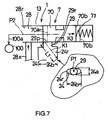
- a flow control valve 7 (illustrated in FIG. 7) disposed in the discharged passage 28 operates so as to return the excess oil in the discharged passage 28 to the suction passage 24 maintained at a relatively low pressure level via the bypass passage 29, i.e. in a direction indicated by an arrow K1. Therefore, the excess oil supplied to the discharged passage 28 is adjusted to an appropriate oil amount such that the oil with the appropriate oil amount can be supplied to a hydraulic equipment 100 (illustrated in FIG. 2).
- a supercharge effect can be expected when the oil in the discharged passage 28 is returned to the suction passage 24 via the bypass passage 29.
- the suction hole 6 is located adjacent to the discharged passage 28, the oil can be introduced to the suction passage 24 from the suction hole 6 with an enhanced suction efficiensy.
- a central axis P5 of the suction hole 6 possesses a space ⁇ X (i.e. a predetermined distance) relative to the central axis P1 of the suction passage 24, i.e. relative to the central axis of the bypass passage 29.
- the suction hole 6 is attached with a suction portion 64 having a suction cylinder 65 via a ring-shaped sealing portion 64s and a ring-shaped fixing portion 64w.
- the oil flows from the suction cylinder 65, a bore 64m of the suction portion 64, the suction passage 24, the suction communicating passage 26, the suction ports 27, the chambers 33, the discharging ports 19, the discharging chamber 12, the discharged passage 28, and the hydraulic pressure equipment 100.
- the flow control valve 7 is employed for adjusting the amount of the oil in the discharged passage 28.
- the flow control valve 7 includes a spool 70 disposed in a reciprocable manner in the discharged passage 28 and a bias spring 71 for biasing the spool 70 in a direction for closing an inlet opening 29p of the bypass passage 29.
- the spool 70 includes a front end surface 70a and a rear end surface 70b.
- the oil in the discharging ports 19 and the discharging chamber 12 is supplied to the discharged passage 28 via a supply passage 28x defined in the housing 13.
- the oil is further supplied to the hydraulic equipment 100 via an oil passage 100a.
- the spool 70 When the oil supplied to the discharged passage 28 exceed the appropriate oil amount, the spool 70 is moved in a direction indicated by an arrow K3, i.e. in a direction for elastically compressing the bias spring 71 with the pressure of the oil in the discharged passage 28, wherein an opening area of the inlet opening 29p of the bypass passage 29 is increased. Accordingly, the excess oil in the discharged passage 28 can be supplied to the suction passage 24 maintained at the relatively low pressure level via the bypass passage 29 in the direction indicated by the arrow K1. In this case, the oil from the discharged passage 28 can be appropriately supplied to the hydraulic equipment 100 via the oil passage 100a.
- the oil in the discharged passage 28 maintained at a relatively high pressure level is returned to the suction passage 24 maintained at the relatively low pressure level in the direction indicated by the arrow K1
- the oil is generally returned in a fairly high return speed.
- an inside of the discharged passage 28 is maintained at a relatively high pressure level with a relatively large oil amount, wherein the oil is generally returned in a fairly high return speed.
- the suction passage 24 possesses the elliptic or oval cross-sectional shape with the major diameter 24b and the minor diameter 24a. As illustrated in FIG. 2, the major diameter 24b extends along the extending direction of the central axis P2 of the discharged passage 28.
- a distance L1 from the inlet opening 29p of the bypass passage 29 to an inner peripheral surface of the suction passage 24 can be designed to be longer than a distance therebetween of a suction passage 24 possessing a perfect circular cross-sectional shape. Therefore, the structure of the suction passage 24 according to the embodiment of the present invention is effective to absorb a direct contact of the returning oil with the suction passage 24.
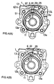
- FIG. 3 (A) is a sectional view taken along an orthogonal direction relative to the central axis P1 of the suction passage 24, and shows the opening center 51x of the drain outlet 51.
- the opening center 51x of the drain outlet 51 is designed to be positioned outwardly from the inner peripheral surface 24r of the suction passage 24 or an extended line thereof. That is, the opening ' center 51x of the drain outlet 51 is defined in a direction indicated by an arrow N1 in FIG. 3 (A) so as to be away from the central axis P1 of the suction passage 24. Therefore, in the case that when the oil pump apparatus has been designed to be able to generate a relatively high oil pressure and amount, the drained oil flow from the drain outlet 51 can be restrained from being affected by the oil flow from the discharged passage 28 to the suction passage 24 via the bypass passage 29.
- a drain performance for draining the oil from the drain outlet 51 can be effectively restrained from being deteriorated.
- the oil leaked in the shaft aperture 21 can be hence surely drained from the drain outlet 51 via the drain inlet 50 and the drain connecting passage 52.
- a pressure of the seal member 45 can be restrained from being increased, thereby enabling to restraining a early wear-out of the seal lip portion 45a of the seal member 45, and further enabling to restraining a drop-off of the seal member 45.
- the opening center 51x of the drain outlet 51 of the comparable oil pump apparatus is defined to be positioned inwardly from the inner peripheral surface 24r of the suction passage 24. That is, the opening center 51x of the drain outlet 51 is defined in a direction indicated by an arrow N2 in FIG. 3 (B). Therefore, the oil drained from the drain outlet 51 can be easily affected by the oil flow into the suction passage 24. Therefore, especially when the oil pump apparatus has been designed to be able to generate a relatively high oil pressure and amount, the drain outlet 51 can be directly affected by the oil flow into the suction passage 24.
- the oil leaked at the shaft aperture 21 may not be appropriately drained from the drain outlet 51.
- the pressure in the shaft aperture 21 may be unnecessarily increased.
- the seal lip portion 45a of the seal member 45 may be worn out earlier than expected. In this case, the seal member 45 may be dropped out of the seal disposing portion 13b.
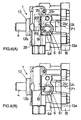
- FIG. 5 (A) is a sectional view taken in parallel with the center axis P1 of the suction passage 24, and shows the opening center 51x of the drain outlet 51.
- an imaginary line P3 is defined to imaginarily connect the central axis P2 of the discharged passage 28 and the central axis P1 of the suction passage 24.
- the opening center 51x of the drain outlet 51 is defined to be positioned at the shaft aperture 21 side, i.e. in a direction indicated by an arrow N3, so as to be away from the imaginary line P3. Therefore, the drain outlet 51 of the drain bore 5 can be effectively restrained from being affected by the oil flow into the suction passage 24.
- the oil can be surely drained from the drain outlet 51 to the suction passage 24, thereby enabling to restrain the pressure increase around the seal member 45, enabling to restrain early wear-out of the seal lip portion 45a, and enabling to restrain drop-off of the seal member 45.
- the opening center 51x of the drain outlet 51 of the comparable oil pump apparatus is defined to be overlapped on the imaginary line P3.
- the oil drained from the drain outlet 51 may be easily affected by the oil flow into the suction passage 24.
- the oil pressure apparatus has been designed to be able to generate a relatively high oil pressure and amount, the oil may not be sufficiently able to be drained from the drain outlet 51.
- the sea lip portion 45a may be worn out earlier than expected. Further, the seal member 45 may be dropped out of the seal disposing portion 13b.
- the drain outlet 51 As illustrated in FIG. 6 (A), the drain outlet 51 according to the embodiment of the present invention is designed to be fairly away from the central axis Pi of the suction passage 24 comparing with the drain outlet 51 of a comparable oil pump apparatus illustrated in FIG. 6(B).
- the opening center 51x of the drain outlet 51 is designed to be positioned outwardly from the inner peripheral surface 24r or the extension thereof. That is, the opening center 51x of the drain outlet 51 is defined in the direction indicated by the arrow N1 in FIG. 3 (A) and is defined to be away from the central axis P1 of the suction passage 24.
- the opening center 51x of the drain outlet 51 is defined to be positioned at the shaft aperture 21 side.
- the drain outlet 51 of the drain bore 5 can be defined in any one of the above-described two manners or in a combined manner of the above-described two manners.
- the oil flows in the suction passage 24 along a direction indicated by an arrow W.
- the oil from the discharged passage 28 to the suction passage 24 via the bypass passage 29 flows in the same direction indicated by the arrow W.
- the drain outlet 51 faces a portion facing the suction passage 24 of the suction cylinder 6.
- the drain outlet 51 can face the only suction passage 24 or the only bypass passage 29.
- the vane type oil pump apparatus is employed as an oil pump apparatus.
- a gear oil pump apparatus can be applicable.
- the suction passage 24 possesses the elliptic or oval axial sectional shape with the major diameter 24b and the minor diameter 24a.
- the suction passage 24 can possess a perfect circular axial sectional shape.
- the drain outlet 51 of the drain bore 5 is defined in any one of the above-described two manners (FIG. 3 (A), or FIG. 5 (A)) or in the combined manner of the above-desclzbed two manners.
- the drain outlet 51 can be defined to be away from the central axis P1 of the suction passage 24. Therefore, even when the oil pump apparatus has been designed to be able to generate a relatively high oil pressure and amount, the oil drained from the drain outlet 51 can be effectively restrained from being affected by the oil flow into the suction passage 24, thereby enabling to assure the oil drain performance from the drain outlet 51.
- the pressure of the seal member 45 can be effectively restrained from being increased, the seal lip portion 45a of the seal member 45 can be effectively restrained from being worn-out earlier than expected, and the sealing member 45 can be effectively restrained from being dropped off. This may be able to lead to improvement of a reliability of the oil pump apparatus.
Landscapes
- Engineering & Computer Science (AREA)
- Mechanical Engineering (AREA)
- General Engineering & Computer Science (AREA)
- Physics & Mathematics (AREA)
- Fluid Mechanics (AREA)
- Rotary Pumps (AREA)
- Details And Applications Of Rotary Liquid Pumps (AREA)
Abstract
Description
Claims (20)
- An oil pump apparatus comprising:wherein an opening center of the drain outlet is positioned outwardly from an inner peripheral surface of the suction passage or from an extended line of the inner peripheral surface somewhere around the opening center of the drain outlet exists so as to take along an orthogonal direction relative to a central axis of the suction passage.a base portion including:an operating chamber;a shaft aperture;a suction port;a discharging port;a suction passage supplying an oil to the suction port; anda discharged passage discharged with the oil from the discharging port;a rotating means disposed in the operating chamber for its rotation and acting as a pump introducing the oil in the suction passage to the operating chamber via the suction port and supplying the oil to the discharged passage via the discharging port;a drive shaft disposed in the shaft aperture for its rotation so as to rotate the rotating means;a sealing means disposed in a boundary between an outer peripheral surface of the drive shaft and an inner peripheral surface of the shaft aperture so as to seal the boundary; anda drain bore including:a drain inlet communicating with the shaft aperture;a drain outlet communicating with the suction passage; anda drain connecting passage connecting the drain inlet and the drain outlet, wherein an excess oil in the shaft aperture is introduced from the drain inlet for draining the oil and is drained from the drain outlet via the drain connecting passage,
- An oil pump apparatus comprising:wherein an opening center of the drain outlet is positioned at a side of the shaft aperture to be away from an imaginary line connecting a central axis of the discharged passage and a central axis of the suction passage somewhere around the opening center of the drain outlet exists so as to take in parallel with the central axis of the suction passage, such that the opening center of the drain outlet is not overlapped on the imaginary line.a base portion including:an operating chamber;a shaft aperture;a suction port;a discharging port;a suction passage supplying an oil to the suction; anda discharged passage discharged with the oil from the discharging port;a rotating means disposed in the operating chamber for its rotation and acting as a pump introducing the oil in the suction passage to the operating chamber via the suction port and supplying the oil to the discharged passage via the discharging port;a drive shaft disposed in the shaft aperture for its rotation so as to rotate the rotating means;a sealing means disposed in a boundary between an outer peupheral surface of the drive shaft and an inner peripheral surface of the shaft aperture so as to seal the boundary; anda drain bore including:a drain inlet communicating with the shaft aperture;a drain outlet communicating with the suction passage; anda drain connecting passage connecting the drain inlet and the drain outlet, wherein an excess oil in the shaft aperture is introduced from the drain inlet for draining the oil and is drained from the drain outlet via the drain connecting passage,
- An oil pump apparatus comprising:wherein an opening center of the drain outlet is positioned outwardly from an inner peupheral surface of the suction passage or from an extended line of the inner peripheral surface somewhere around the opening center of the drain outlet exists so as to take along an orthogonal direction relative to a central axis of the suction passage, anda base portion including:an operating chamber;a shaft aperture;a suction port;a discharging port;a suction passage supplying an oil to the suction port; anda discharged passage discharged with the oil from the discharging port;a rotating means disposed in the operating chamber for its rotation and acting as a pump introducing the oil in the suction passage to the operating chamber via the suction port and supplying the oil to the discharged passage via the discharging port;a drive shaft disposed in the shaft aperture for its rotation so as to rotate the rotating means;a sealing means disposed in a boundary between an outer peripheral surface of the drive shaft and an inner peripheral surface of the shaft aperture so as to seal the boundary; anda drain bore including:a drain inlet communicating with the shaft aperture;a drain outlet communicating with the suction passage; anda drain connecting passage connecting the drain inlet and the drain outlet, wherein an excess oil in the shaft aperture is introduced from the drain inlet for draining the oil and is drained from the drain outlet via the drain connecting passage,
wherein the opening center of the drain outlet is positioned at a side of the shaft aperture to be away from an imaginary line connecting a central axis of the discharged passage and a central axis of the suction passage somewhere around the opening center of the drain outlet exists so as to take in parallel with the central axis of the suction passage, such that the opening center of the drain outlet is not overlapped on the imaginary line. - An oil pump apparatus according to claim 1, further comprising:a suction hole possessing a cylindrical shaped structure with an end surface facing the suction passage, wherein the opening center of the drain outlet is defined at the end surface of the suction hole.
- An oil pump apparatus according to claim 4, wherein, a central axis of the suction hole deviates from the central axis of the suction passage with a predetermined distance therefrom.
- An oil pump apparatus according to claim 1, wherein the opening center of the drain outlet is defined at the suction passage.
- An oil pump apparatus according to claim 1, further composing:wherein the opening center of the drain outlet is defined at the bypass passage. .a bypass passage connecting the discharged passage and the suction passage, '
- An oil pump apparatus according to claim 1, wherein the suction passage possesses an oval cross-sectional shape with a first diameter and a second diameter of which length is longer than one of the first diameter.
- An oil pump apparatus according to claim 4, wherein a central axis of the drain connecting passage extends to a radially inner side of the suction hole than an inner periphery thereof.
- An oil pump apparatus according to claim 2, further comprising:a suction hole possessing a cylindrical shaped structure with an end surface facing the suction passage, wherein the opening center of the drain outlet is defined at the end surface of the suction hole.
- An oil pump apparatus according to claim 2, wherein the opening center of the drain outlet is defined at the suction passage.
- An oil pump apparatus according to claim 2, further composing:wherein the opening center of the drain outlet is defined at the bypass passage.a bypass passage connecting the discharged passage and the suction passage,
- An oil pump apparatus according to claim 2, wherein the suction passage possesses an oval cross-sectional shape with a first diameter and a second diameter of which length is longer than one of the first diameter.
- An oil pump apparatus according to claim 10, wherein a central axis of the drain connecting passage extends to a radially inner side of the suction hole than an inner periphery thereof.
- An oil pump apparatus according to claim 3, further comprising:a suction hole possessing a cylindrical shaped structure with an end surface facing the suction passage, wherein the opening center of the drain outlet is defined at the end surface of the suction hole.
- An oil pump apparatus according to claim 15, wherein, a central axis of the suction hole deviates from the central axis of the suction passage with a predetermined distance therefrom.
- An oil pump apparatus according to claim 3, wherein the opening center of the drain outlet is defined at the suction passage.
- An oil pump apparatus according to claim 3, further comprising:wherein the opening center of the drain outlet is defined at the bypass passage.a bypass passage connecting the discharged passage and the suction passage,
- An oil pump apparatus according to claim 3, wherein the suction passage possesses an oval cross-sectional shape with a first diameter and a second diameter of which length is longer than one of the first diameter.
- An oil pump apparatus according to claim 15, wherein a central axis of the drain connecting passage extends to a radially inner side of the suction hole than an inner periphery thereof.
Applications Claiming Priority (2)
| Application Number | Priority Date | Filing Date | Title |
|---|---|---|---|
| JP2002178322A JP4245863B2 (en) | 2002-06-19 | 2002-06-19 | Oil pump |
| JP2002178322 | 2002-06-19 |
Publications (2)
| Publication Number | Publication Date |
|---|---|
| EP1375922A2 true EP1375922A2 (en) | 2004-01-02 |
| EP1375922A3 EP1375922A3 (en) | 2006-09-06 |
Family
ID=29717482
Family Applications (1)
| Application Number | Title | Priority Date | Filing Date |
|---|---|---|---|
| EP03013963A Withdrawn EP1375922A3 (en) | 2002-06-19 | 2003-06-20 | Oil vane pump |
Country Status (3)
| Country | Link |
|---|---|
| US (1) | US7070396B2 (en) |
| EP (1) | EP1375922A3 (en) |
| JP (1) | JP4245863B2 (en) |
Families Citing this family (1)
| Publication number | Priority date | Publication date | Assignee | Title |
|---|---|---|---|---|
| US10060775B2 (en) | 2014-03-10 | 2018-08-28 | Driblet Labs, LLC | Smart water management system |
Family Cites Families (8)
| Publication number | Priority date | Publication date | Assignee | Title |
|---|---|---|---|---|
| US4424014A (en) * | 1981-06-08 | 1984-01-03 | General Motors Corporation | Power steering pump drive shaft seal area drain structure |
| JPS60178987A (en) * | 1984-02-24 | 1985-09-12 | Toyoda Mach Works Ltd | Pumping apparatus |
| JPS63167089A (en) * | 1986-12-27 | 1988-07-11 | Kayaba Ind Co Ltd | Vane pump |
| JP2867285B2 (en) * | 1990-03-09 | 1999-03-08 | 自動車機器株式会社 | Vane pump |
| JPH0587062A (en) * | 1991-09-25 | 1993-04-06 | Toyoda Mach Works Ltd | Variable capacity type vane pump device |
| JP4342647B2 (en) * | 1999-08-20 | 2009-10-14 | 株式会社ショーワ | Back pressure groove structure of variable displacement vane pump |
| JP4070391B2 (en) * | 2000-06-15 | 2008-04-02 | カヤバ工業株式会社 | Vane pump pressure regulator |
| JP3874694B2 (en) * | 2002-04-26 | 2007-01-31 | 株式会社ジェイテクト | Oil pump device |
-
2002
- 2002-06-19 JP JP2002178322A patent/JP4245863B2/en not_active Expired - Fee Related
-
2003
- 2003-06-19 US US10/464,561 patent/US7070396B2/en not_active Expired - Fee Related
- 2003-06-20 EP EP03013963A patent/EP1375922A3/en not_active Withdrawn
Also Published As
| Publication number | Publication date |
|---|---|
| US7070396B2 (en) | 2006-07-04 |
| EP1375922A3 (en) | 2006-09-06 |
| JP4245863B2 (en) | 2009-04-02 |
| JP2004019609A (en) | 2004-01-22 |
| US20040208755A1 (en) | 2004-10-21 |
Similar Documents
| Publication | Publication Date | Title |
|---|---|---|
| JP3531769B2 (en) | Oil pump device | |
| US8695548B2 (en) | Valve timing control apparatus | |
| CN107304765B (en) | Rotary pump comprising a lubrication groove in the sealing seat | |
| JP5443428B2 (en) | Vane pump | |
| EP1243794A2 (en) | Vane hydraulic motor | |
| US9291163B2 (en) | Pump having fitting portions | |
| US20110176909A1 (en) | Vehicle hydraulic control unit | |
| KR100289782B1 (en) | Hydraulic pump | |
| JPH01247767A (en) | Internal contact gear motor | |
| US6544013B2 (en) | Oil pump apparatus | |
| JP6534647B2 (en) | Vane pump | |
| US7070396B2 (en) | Oil pump apparatus having oil drain | |
| US20170356444A1 (en) | Transfer device | |
| US20060120896A1 (en) | Oil pump | |
| US5273408A (en) | Variable-displacement vane pump | |
| CN109923313B (en) | Vane pump | |
| US6048185A (en) | Hydraulic pumps | |
| US20180245589A1 (en) | Variable oil pump | |
| CN100379990C (en) | vane pump | |
| US8197238B2 (en) | Pump apparatus | |
| EP0753449B1 (en) | Flow control device of power steering system | |
| JP3732621B2 (en) | Hydraulic pump | |
| JP2005036686A (en) | Hydraulic pump | |
| JPH03134280A (en) | Oil pump for vehicle | |
| JP3546740B2 (en) | Oil pump device |
Legal Events
| Date | Code | Title | Description |
|---|---|---|---|
| PUAI | Public reference made under article 153(3) epc to a published international application that has entered the european phase |
Free format text: ORIGINAL CODE: 0009012 |
|
| AK | Designated contracting states |
Kind code of ref document: A2 Designated state(s): AT BE BG CH CY CZ DE DK EE ES FI FR GB GR HU IE IT LI LU MC NL PT RO SE SI SK TR |
|
| AX | Request for extension of the european patent |
Extension state: AL LT LV MK |
|
| PUAL | Search report despatched |
Free format text: ORIGINAL CODE: 0009013 |
|
| AK | Designated contracting states |
Kind code of ref document: A3 Designated state(s): AT BE BG CH CY CZ DE DK EE ES FI FR GB GR HU IE IT LI LU MC NL PT RO SE SI SK TR |
|
| AX | Request for extension of the european patent |
Extension state: AL LT LV MK |
|
| RAP1 | Party data changed (applicant data changed or rights of an application transferred) |
Owner name: JTEKT CORPORATION |
|
| RIN1 | Information on inventor provided before grant (corrected) |
Inventor name: ETO, ATSUSHI Inventor name: YAMUCHI, KENTARO |
|
| 17P | Request for examination filed |
Effective date: 20070302 |
|
| AKX | Designation fees paid |
Designated state(s): DE FR GB |
|
| 17Q | First examination report despatched |
Effective date: 20071031 |
|
| STAA | Information on the status of an ep patent application or granted ep patent |
Free format text: STATUS: THE APPLICATION IS DEEMED TO BE WITHDRAWN |
|
| 18D | Application deemed to be withdrawn |
Effective date: 20110104 |