EP1375208A1 - Heating, ventilating and air conditioning module having an improved heater core configuration - Google Patents
Heating, ventilating and air conditioning module having an improved heater core configuration Download PDFInfo
- Publication number
- EP1375208A1 EP1375208A1 EP03076796A EP03076796A EP1375208A1 EP 1375208 A1 EP1375208 A1 EP 1375208A1 EP 03076796 A EP03076796 A EP 03076796A EP 03076796 A EP03076796 A EP 03076796A EP 1375208 A1 EP1375208 A1 EP 1375208A1
- Authority
- EP
- European Patent Office
- Prior art keywords
- heater core
- air
- set forth
- assembly
- further defined
- Prior art date
- Legal status (The legal status is an assumption and is not a legal conclusion. Google has not performed a legal analysis and makes no representation as to the accuracy of the status listed.)
- Granted
Links
Images



Classifications
-
- F—MECHANICAL ENGINEERING; LIGHTING; HEATING; WEAPONS; BLASTING
- F28—HEAT EXCHANGE IN GENERAL
- F28D—HEAT-EXCHANGE APPARATUS, NOT PROVIDED FOR IN ANOTHER SUBCLASS, IN WHICH THE HEAT-EXCHANGE MEDIA DO NOT COME INTO DIRECT CONTACT
- F28D1/00—Heat-exchange apparatus having stationary conduit assemblies for one heat-exchange medium only, the media being in contact with different sides of the conduit wall, in which the other heat-exchange medium is a large body of fluid, e.g. domestic or motor car radiators
- F28D1/02—Heat-exchange apparatus having stationary conduit assemblies for one heat-exchange medium only, the media being in contact with different sides of the conduit wall, in which the other heat-exchange medium is a large body of fluid, e.g. domestic or motor car radiators with heat-exchange conduits immersed in the body of fluid
- F28D1/04—Heat-exchange apparatus having stationary conduit assemblies for one heat-exchange medium only, the media being in contact with different sides of the conduit wall, in which the other heat-exchange medium is a large body of fluid, e.g. domestic or motor car radiators with heat-exchange conduits immersed in the body of fluid with tubular conduits
- F28D1/047—Heat-exchange apparatus having stationary conduit assemblies for one heat-exchange medium only, the media being in contact with different sides of the conduit wall, in which the other heat-exchange medium is a large body of fluid, e.g. domestic or motor car radiators with heat-exchange conduits immersed in the body of fluid with tubular conduits the conduits being bent, e.g. in a serpentine or zig-zag
-
- B—PERFORMING OPERATIONS; TRANSPORTING
- B60—VEHICLES IN GENERAL
- B60H—ARRANGEMENTS OF HEATING, COOLING, VENTILATING OR OTHER AIR-TREATING DEVICES SPECIALLY ADAPTED FOR PASSENGER OR GOODS SPACES OF VEHICLES
- B60H1/00—Heating, cooling or ventilating devices
- B60H1/00007—Combined heating, ventilating, or cooling devices
- B60H1/00021—Air flow details of HVAC devices
- B60H1/00028—Constructional lay-out of the devices in the vehicle
-
- B—PERFORMING OPERATIONS; TRANSPORTING
- B60—VEHICLES IN GENERAL
- B60H—ARRANGEMENTS OF HEATING, COOLING, VENTILATING OR OTHER AIR-TREATING DEVICES SPECIALLY ADAPTED FOR PASSENGER OR GOODS SPACES OF VEHICLES
- B60H1/00—Heating, cooling or ventilating devices
- B60H1/00321—Heat exchangers for air-conditioning devices
- B60H1/00328—Heat exchangers for air-conditioning devices of the liquid-air type
-
- F—MECHANICAL ENGINEERING; LIGHTING; HEATING; WEAPONS; BLASTING
- F28—HEAT EXCHANGE IN GENERAL
- F28D—HEAT-EXCHANGE APPARATUS, NOT PROVIDED FOR IN ANOTHER SUBCLASS, IN WHICH THE HEAT-EXCHANGE MEDIA DO NOT COME INTO DIRECT CONTACT
- F28D1/00—Heat-exchange apparatus having stationary conduit assemblies for one heat-exchange medium only, the media being in contact with different sides of the conduit wall, in which the other heat-exchange medium is a large body of fluid, e.g. domestic or motor car radiators
- F28D1/02—Heat-exchange apparatus having stationary conduit assemblies for one heat-exchange medium only, the media being in contact with different sides of the conduit wall, in which the other heat-exchange medium is a large body of fluid, e.g. domestic or motor car radiators with heat-exchange conduits immersed in the body of fluid
- F28D1/04—Heat-exchange apparatus having stationary conduit assemblies for one heat-exchange medium only, the media being in contact with different sides of the conduit wall, in which the other heat-exchange medium is a large body of fluid, e.g. domestic or motor car radiators with heat-exchange conduits immersed in the body of fluid with tubular conduits
- F28D1/053—Heat-exchange apparatus having stationary conduit assemblies for one heat-exchange medium only, the media being in contact with different sides of the conduit wall, in which the other heat-exchange medium is a large body of fluid, e.g. domestic or motor car radiators with heat-exchange conduits immersed in the body of fluid with tubular conduits the conduits being straight
- F28D1/0535—Heat-exchange apparatus having stationary conduit assemblies for one heat-exchange medium only, the media being in contact with different sides of the conduit wall, in which the other heat-exchange medium is a large body of fluid, e.g. domestic or motor car radiators with heat-exchange conduits immersed in the body of fluid with tubular conduits the conduits being straight the conduits having a non-circular cross-section
- F28D1/05366—Assemblies of conduits connected to common headers, e.g. core type radiators
- F28D1/05375—Assemblies of conduits connected to common headers, e.g. core type radiators with particular pattern of flow, e.g. change of flow direction
-
- B—PERFORMING OPERATIONS; TRANSPORTING
- B60—VEHICLES IN GENERAL
- B60H—ARRANGEMENTS OF HEATING, COOLING, VENTILATING OR OTHER AIR-TREATING DEVICES SPECIALLY ADAPTED FOR PASSENGER OR GOODS SPACES OF VEHICLES
- B60H1/00—Heating, cooling or ventilating devices
- B60H1/00007—Combined heating, ventilating, or cooling devices
- B60H1/00021—Air flow details of HVAC devices
- B60H2001/00078—Assembling, manufacturing or layout details
- B60H2001/00107—Assembling, manufacturing or layout details characterised by the relative position of the heat exchangers, e.g. arrangements leading to a curved airflow
-
- F—MECHANICAL ENGINEERING; LIGHTING; HEATING; WEAPONS; BLASTING
- F28—HEAT EXCHANGE IN GENERAL
- F28D—HEAT-EXCHANGE APPARATUS, NOT PROVIDED FOR IN ANOTHER SUBCLASS, IN WHICH THE HEAT-EXCHANGE MEDIA DO NOT COME INTO DIRECT CONTACT
- F28D1/00—Heat-exchange apparatus having stationary conduit assemblies for one heat-exchange medium only, the media being in contact with different sides of the conduit wall, in which the other heat-exchange medium is a large body of fluid, e.g. domestic or motor car radiators
- F28D1/02—Heat-exchange apparatus having stationary conduit assemblies for one heat-exchange medium only, the media being in contact with different sides of the conduit wall, in which the other heat-exchange medium is a large body of fluid, e.g. domestic or motor car radiators with heat-exchange conduits immersed in the body of fluid
- F28D2001/0253—Particular components
- F28D2001/026—Cores
- F28D2001/0273—Cores having special shape, e.g. curved, annular
-
- F—MECHANICAL ENGINEERING; LIGHTING; HEATING; WEAPONS; BLASTING
- F28—HEAT EXCHANGE IN GENERAL
- F28D—HEAT-EXCHANGE APPARATUS, NOT PROVIDED FOR IN ANOTHER SUBCLASS, IN WHICH THE HEAT-EXCHANGE MEDIA DO NOT COME INTO DIRECT CONTACT
- F28D21/00—Heat-exchange apparatus not covered by any of the groups F28D1/00 - F28D20/00
- F28D2021/0019—Other heat exchangers for particular applications; Heat exchange systems not otherwise provided for
- F28D2021/008—Other heat exchangers for particular applications; Heat exchange systems not otherwise provided for for vehicles
- F28D2021/0091—Radiators
- F28D2021/0096—Radiators for space heating
-
- Y—GENERAL TAGGING OF NEW TECHNOLOGICAL DEVELOPMENTS; GENERAL TAGGING OF CROSS-SECTIONAL TECHNOLOGIES SPANNING OVER SEVERAL SECTIONS OF THE IPC; TECHNICAL SUBJECTS COVERED BY FORMER USPC CROSS-REFERENCE ART COLLECTIONS [XRACs] AND DIGESTS
- Y10—TECHNICAL SUBJECTS COVERED BY FORMER USPC
- Y10S—TECHNICAL SUBJECTS COVERED BY FORMER USPC CROSS-REFERENCE ART COLLECTIONS [XRACs] AND DIGESTS
- Y10S165/00—Heat exchange
- Y10S165/903—Convection
Definitions
- the subject invention relates to an improved heater core configuration for a heating, ventilating, and air conditioning module.
- HVAC Automotive heating, ventilating, and air conditioning
- a hollow housing disposed within in a vehicle.
- the heater core is usually located within a lower quadrant of the housing and is used to heat the air that flows into a passenger compartment of the vehicle.
- the subject invention includes a heating, ventilating, and air conditioning (HVAC) assembly or module for heating, venting, and cooling a passenger compartment of a vehicle.
- HVAC heating, ventilating, and air conditioning
- the HVAC module comprises a hollow housing having an inlet and at least one outlet for directing a flow of air into the passenger compartment.
- a first heat exchanger preferably an evaporator core
- a second heat exchanger is disposed within the housing between the evaporator core and the outlet with the heater core having an upstream surface generally facing the evaporator core and a downstream surface generally facing the outlet.
- the heater core includes a first portion and a second portion being angled relative to the first portion such that the upstream surface of the first portion at least partially faces the upstream surface of the second portion to define an angled heater core facing the evaporator core wherein air flowing over the upstream surfaces is evenly distributed across both of the first and second portions, thereby increasing the effectiveness of the heater core.
- the subject invention also includes a method of optimizing a flow of air over the angled heater core.
- the method comprises the steps of; measuring an incoming temperature of the air adjacent the upstream surface of the heater core; measuring an outgoing temperature of the air adjacent the downstream surface of the heater core; calculating a variance between the incoming and outgoing temperatures of the air to determine a temperature increase across the heater core; measuring an incoming pressure of the air adjacent the upstream surface of the heater core; measuring an outgoing pressure of the air adjacent the downstream surface of the heater core; calculating a variance between the incoming and outgoing pressures of the air to determine a pressure drop across the heater core; and adjusting the angular position the first portion of the heater core relative to the second portion of the heater core until the temperature increase across the heater core is maximized and the pressure drop across the heater core is minimized, thereby determining the optimum relative positions of the first and second portions for the angled heater core.
- the subject invention sets forth an improved heater core which is angled such that air uniformly flows over an entire outer surface of the heater core while maximizing a temperature increase across the heater core and minimizing a pressure drop across the heater core.
- HVAC heating, ventilating, and air conditioning
- the upper passenger compartment outlet 18 distributes air to an upper duct (not shown) which in turn transfers the air to passenger vents disposed along a dashboard (not shown).
- the lower passenger compartment outlet 20 distributes air to a lower duct (not shown) which in turn transfers the air to a floorboard or foot area vents (not shown).
- Arrows are provided to illustrate the flow of air through the housing 12 and the outlets 16,18,20.
- the general configuration of the housing 12 and location and number of outlets are well known to those skilled in the HVAC art and may be of any suitable design.
- a first heat exchanger 22 is disposed within the housing 12 downstream of the inlet 14 and upstream from the outlets 16,18,20.
- the first heat exchanger 22 is an evaporator core 22.
- the evaporator core 22 is arranged and configured to intercept substantially all of the air flowing into the passenger compartment.
- the housing 12 includes an evaporator core mounting area 24 which is positioned adjacent the inlet 14 of the housing 12.
- the evaporator core 22 is secured to the housing 12 in the evaporator core 22 mounting area 24 and is large enough to completely extend across the inlet 14. Hence, air flowing from the inlet 14 toward the outlets 16,18,20 passes through the evaporator core 22.
- the evaporator core 22 cools and dehumidifies the air flowing therethrough as is known in the HVAC art. It should also be appreciated that the evaporator core 22 may be of any suitable design or configuration without deviating from the scope of the subject invention.
- a second heat exchanger 26 is also disposed within the housing 12 between the evaporator core 22 and the outlets 16,18,20.
- the second heat exchanger 26 is a heater core 26 with the heater core 26 having an upstream surface 28 generally facing the evaporator core 22 and a downstream surface 30 generally facing the outlet 16,18,20.
- the heater core 26 includes opposing manifolds 31 with a plurality of fins 32 and tubes 33 extending along the length thereof between the manifolds 31. Inlet 35 and outlet 37 ports are disposed on one or more of the manifolds 31 to transfer liquid through the tubes 33 between the manifolds 31 thereby facilitating the necessary heat transfer between the liquid and the air.
- the fins 32, tubes 33, manifolds 31 and remaining portions of the heater core 26 are designed and configured in a manner known to those skilled in the heat exchanger arts. Further details of the preferred heater core 26 will be discussed in greater detail below.
- the housing 12 further includes an upper quadrant 34 and a lower quadrant 36 with the evaporator core 22 disposed within both of the quadrants and the heater core 26 disposed within the lower quadrant 36. Hence, air flowing through the upper quadrant 34 will be for venting and cooling, and air flowing through the lower quadrant 36 will be for heating.
- At least one, and preferably more than one, flow valve 38 is disposed within the housing 12 for controlling the flow of air between the upper 34 and lower 36 quadrants.
- the flow valve 38 directs the flow of air such that heated, vented, and/or cooled air can be distributed through the outlets 16,18,20 as desired.
- the heater core 26 includes a first portion 40 and a second portion 42 being angled relative to the first portion 40.
- the angled heater core 26 faces the evaporator core 22 such that the upstream surface 28 of the first portion 40 at least partially faces the upstream surface 28 of the second portion 42. Because of this angled feature, air flowing over the upstream surfaces 28 is more evenly distributed across both of the first 40 and second 42 portions, thereby increasing the effectiveness of the heater core 26, see Figure 5. In other words, the temperature increase across the heater core 26 is maximized and the pressure drop across the heater core 26 is minimized.
- Each of the first 40 and second 42 portions preferably have a substantially flat rectangular configuration with a central region and a peripheral region. The central regions abut each other such that the first 40 and second 42 portions create a continuous angled heater core 26.
- FIG. 3A and 3B illustrate a first embodiment of the heater core 26 wherein the fins 32 and tubes 33 extend in a vertical direction when mounted in the housing 12.
- the fins 32 and tubes 33 are bent at the intersection of the central regions to define the angled heater core 26.
- Figures 4A and 4B illustrate a second embodiment of the heater core 26 wherein the fins 32 and tubes 33 extend in a horizontal direction when mounted in the housing 12.
- the fins 32 can be spaced in a uniform or non-uniform manner. As best shown in Figures 1, 2, 3A, and 4A the plurality of fins 32 are spaced apart in a non-uniform manner.
- the fins 32 are unequally spaced throughout at least one of the central and peripheral regions.
- the fins 32 have a higher density in the central region of the first portion 40 where the incurring air flow rate is higher.
- the tubes 33 may be spaced apart in a non-uniform manner in conjunction with or instead of the fins 32.
- the tubes 33 and/or fins 32 are unequally spaced throughout at least one of the central and peripheral regions.
- the plurality of fins 32 and tubes 33 are alternatively spaced apart in a uniform manner. In other words, both the fins 32 and tubes 33 are equally spaced throughout the central and peripheral regions.
- the air flow is concentrated most in the central region of the first portion 40. Hence, the air velocity is greatest in this region.
- the fins 32 are concentrated in this area.
- the remaining regions of the first 40 and second 42 portions have fins 32 that are spaced farther apart.
- the spacing of fins 32 in the first 40 and second 42 portions controls the velocity of the air flowing through the heater core 26.
- the increased velocity of the air passing through the central region of the first portion 40 is reduced more than the velocity of the air passing through the other regions of the first 40 and second 42 portions. This equates to having a more uniform exit velocity of the air.
- the first portion 40 is angled relative to the second portion 42 by more than 90 degrees.
- the angle between the first 40 and second 42 portions is illustrated in Figures 5 - 7, by the included angle ⁇ .
- the first portion 40 is angled relative to the second portion 42 by an included angle ⁇ of 140 degrees.
- the downstream surface 30 of the first portion 40 is angled relative to the downstream portion of the second portion 42 by an included angle ⁇ of 140 degrees.
- a bend angle ⁇ is also illustrated in Figures 5 - 7 wherein the bend angle ⁇ sets forth the angle of the downstream surfaces 30 of the first 40 and second 42 portions relative to a plane 44.
- the plane 44 is substantially perpendicular to a flow velocity of the air toward the heater core 26, see Figures 5 - 7.
- the total velocity vector of the air toward the heater core 26 is labeled as U ⁇ .
- the velocity vector U ⁇ is split into two different velocity vectors U n and U p .
- Velocity vector un of the air is the normal component of the velocity vector U ⁇ relative to the heater core 26.
- the velocity vector U n denotes the velocity of air that is facing the upstream surface 28 of the heater core 26 and subsequently passes through the heater core 26 to exit out the downstream surface 30 of the heater core 26.
- Velocity vector up of the air is the parallel component of the velocity vector U ⁇ relative to the heater core 26.
- velocity vector Up denotes the velocity of air that runs parallel along the upstream surface 28 of the heater core 26.
- This velocity component, Up defines an inefficiency of the heater core 26 in that a portion of the total velocity of air U ⁇ is not passing through the heater core 26. Therefore, it is desirable to always have the velocity vector u p be smaller than the velocity vector un.
- the bend angle of the heater core 26 directly affects the values of the velocity vectors u n and u p .
- the velocity vectors for u p and u n are illustrated as components of u ⁇ .
- the optimum bend angle ⁇ wherein the velocity vector un is larger than the velocity vector u p , is less than 45 degrees.
- the velocity vector u p would be larger than the velocity vector u n , thereby creating an inefficient heater core 26.
- the velocity vector up would be larger than the velocity vector u n , thereby creating an inefficient heater core 26.
- the bend angle ⁇ the preferred angular position of the first 40 and second 42 portions relative to the plane 44 is less than 45 degrees.
- the bend angle of the heater core 26 also directly affects the temperature increase values and the pressure drop values.
- the change in temperature and change in pressure are illustrated for various different bend angles of the heater core 26.
- the optimum bend angle ⁇ wherein the temperature increase is maximized and the pressure drop is minimized, is 20 degrees.
- the first 40 and second 42 portions of the heater core 26 were angled relative to the plane 44 by a bend angle ⁇ of significantly more or less than 20 degrees, the temperature increase will reduce and the pressure drop will become larger, thereby creating an inefficient heater core 26.
- the preferred included angle ⁇ and bend angle ⁇ discussed above correlate to each other such that the combination of included angle ⁇ plus twice bend angle ⁇ equals 180 degrees.
- the preferred included angles ⁇ and bend angles ⁇ can change depending upon the type, design, and configuration of the heater core 26. A method of ideally determining the included angle ⁇ and bend angle ⁇ for any heat exchanger is set forth in detail below.
- the particular angle of the first portion 40 relative to the second portion 42 is important to the performance of any heat exchanger, including the heater core 26 of the subject invention. If the relative angle between the portions 40,42 is not optimized, then the heater core 26 will not operate at its full effectiveness, i.e., the temperature increase will not be maximized and the pressure drop will not be minimized.
- the subject invention includes a method of optimizing the flow of air over the heater core 26.
- the method comprising the step of calculating a variance between incoming and outgoing temperatures of the air to determine a temperature increase across the heater core 26.
- the method further comprises the step of calculating a variance between incoming and outgoing pressures of the air to determine a pressure drop across the heater core 26.
- the angular position the first portion 40 of the heater core 26 is then adjusted relative to the second portion 42 of the heater core 26 until the temperature increase across the heater core 26 is maximized and the pressure drop across the heater core 26 is minimized. This adjustment of the first 40 and second 42 portions thereby determines the optimum relative positions of the first 40 and second 42 portions for the angled heater core 26.
- One method of calculating the temperature increase across the heater core 26 includes measuring an incoming temperature of the air adjacent the upstream surface 28 of the heater core 26 and measuring an outgoing temperature of the air adjacent the downstream surface 30 of the heater core 26. The outgoing temperature is then subtracted from the incoming temperature to determine the temperature increase. The measurements of the incoming and outgoing temperatures may be accomplished by any suitable device such as a temperature probe.
- one method of calculating the pressure drop across the heater core 26 includes measuring an incoming pressure of the air adjacent the upstream surface 28 of the heater core 26 and measuring an outgoing pressure of the air adjacent the downstream surface 30 of the heater core 26. The incoming pressure is then subtracted from the outgoing pressure to determine the pressure drop. The measurements of the incoming and outgoing pressures may be accomplished in any known manner such as utilizing a pressure probe.
- the step of adjusting the angular position the first portion 40 relative to the second portion 42 is further defined as adjusting the first 40 and second 42 portions until the first portion 40 is angled relative to the second portion 42 by an included angle ⁇ of more than 90 degrees. More preferably, the step of adjusting the angular position of the first portion 40 relative to the second portion 42 is further defined as adjusting the first 40 and second 42 portions until the first portion 40 is angled relative to the second portion 42 by an included angle ⁇ of 140 degrees.
- the step of adjusting the angular position of the first portion 40 relative to the second portion 42 is further defined as adjusting the first 40 and second 42 portions until the downstream surface 30 of the first portion 40 is angled relative to the downstream portion of the second portion 42 by an included angle ⁇ of 140 degrees.
- the step of calculating the temperature increase across the heater core 26 may also be accomplished by utilizing the following formula; where, ⁇ T a is the temperature increase of the air across the heater core 26, is the mass flow rate of the air across the heater core 26, is the mass flow rate of the liquid flowing through the heater core 26, c a is the specific heat of the air, Cc is the specific heat of the liquid passing through the heater core 26, and ⁇ Tc is the temperature decrease of the liquid.
- the step of calculating the temperature increase across the heater core is further defined as subtracting an inlet temperature of the liquid from an outlet temperature of the liquid to obtain the ⁇ Tc temperature decrease.
- one or more of the manifolds 31 include an inlet port 35 and/or an outlet port 37 such that the inlet and outlet temperatures of the liquid can be measured.
- the above formula for calculating the temperature increase eliminates the need for a temperature probe disposed in the airflow path of the air.
- the mass flow rate of the air and the mass flow rate of the liquid are easily determined and the specific heat of the air c a and the specific heat of the liquid Cc are known constants.
- the temperature measurements of the liquid at the inlet 35 and outlet 37 ports can be easily determined.
- the above temperature formula simplifies the process for determining the temperature increase across the heater core 26.
- the step of calculating the pressure drop across the heater core 26 may also be accomplished by utilizing the following formula; where, ⁇ P a is the pressure drop of the air across the heater core 26,
- the above formula for calculating the pressure drop eliminates the need for a pressure probe disposed in the airflow path of the air.
- the values for the coefficient of friction ⁇ , depth of thickness ⁇ of the heater core 26, mass flow rate of the air density of the air ⁇ a , hydraulic diameter of the flow passages d h , and area A of the upstream surface 28 are all known.
- the coefficient of friction or friction factor ⁇ is dependent upon the airside fin configuration within the heater core 26. Hence, the friction factor ⁇ for each of the heater cores 26 shown in Figures 3A - 4B will be different. The remaining value is to determine the bend angle ⁇ .
- the step of adjusting the angular position of the first portion 40 relative to the second portion 42 is further defined as adjusting the first 40 and second 42 portions until the bend angle ⁇ is less than 45 degrees. Even more preferably, the step of adjusting the angular position the first portion 40 relative to the second portion 42 is further defined as adjusting the first 40 and second 42 portions until the bend angle ⁇ is 20 degrees.
Landscapes
- Engineering & Computer Science (AREA)
- Physics & Mathematics (AREA)
- Thermal Sciences (AREA)
- Mechanical Engineering (AREA)
- General Engineering & Computer Science (AREA)
- Air-Conditioning For Vehicles (AREA)
Abstract
Description
- The subject invention relates to an improved heater core configuration for a heating, ventilating, and air conditioning module.
- Automotive heating, ventilating, and air conditioning (HVAC) modules typically incorporate a hollow housing disposed within in a vehicle. An evaporator core and a heater core, as well as various valves for directing a flow of air, are mounted within the housing. The heater core is usually located within a lower quadrant of the housing and is used to heat the air that flows into a passenger compartment of the vehicle.
- There have been numerous designs for the housings and heater cores to maximize the effectiveness of the heater core. As illustrated in U.S. Patent Nos. 5,927,380 and 6,045,444, the heater cores within automotive HVAC modules typically have flat rectangular configurations. The flow of air over the flat rectangular heater cores has a tendency to stagnate in certain areas thereby reducing the operable effectiveness of the heater core.
- Accordingly, it would be desirable to develop a heater core which allows for uniform flow of air over an entire outer surface of the heater core while maximizing a temperature increase across the heater core and minimizing a pressure drop across the heater core.
- The subject invention includes a heating, ventilating, and air conditioning (HVAC) assembly or module for heating, venting, and cooling a passenger compartment of a vehicle. The HVAC module comprises a hollow housing having an inlet and at least one outlet for directing a flow of air into the passenger compartment. A first heat exchanger, preferably an evaporator core, is disposed within the housing downstream of the
inlet 14 and upstream from the outlet with the evaporator core arranged and configured for intercepting substantially all of the air flowing into the passenger compartment. A second heat exchanger, preferably a heater core, is disposed within the housing between the evaporator core and the outlet with the heater core having an upstream surface generally facing the evaporator core and a downstream surface generally facing the outlet. The heater core includes a first portion and a second portion being angled relative to the first portion such that the upstream surface of the first portion at least partially faces the upstream surface of the second portion to define an angled heater core facing the evaporator core wherein air flowing over the upstream surfaces is evenly distributed across both of the first and second portions, thereby increasing the effectiveness of the heater core. - The subject invention also includes a method of optimizing a flow of air over the angled heater core. The method comprises the steps of; measuring an incoming temperature of the air adjacent the upstream surface of the heater core; measuring an outgoing temperature of the air adjacent the downstream surface of the heater core; calculating a variance between the incoming and outgoing temperatures of the air to determine a temperature increase across the heater core; measuring an incoming pressure of the air adjacent the upstream surface of the heater core; measuring an outgoing pressure of the air adjacent the downstream surface of the heater core; calculating a variance between the incoming and outgoing pressures of the air to determine a pressure drop across the heater core; and adjusting the angular position the first portion of the heater core relative to the second portion of the heater core until the temperature increase across the heater core is maximized and the pressure drop across the heater core is minimized, thereby determining the optimum relative positions of the first and second portions for the angled heater core.
- Accordingly, the subject invention sets forth an improved heater core which is angled such that air uniformly flows over an entire outer surface of the heater core while maximizing a temperature increase across the heater core and minimizing a pressure drop across the heater core.
- Other advantages of the present invention will be readily appreciated as the same becomes better understood by reference to the following detailed description when considered in connection with the accompanying drawings wherein:
- Figure 1 is a partially cross sectional perspective view of a heating, ventilating, and air conditioning (HVAC) assembly or module in accordance with the subject invention with a flow valve in a mid position;
- Figure 2 is a partially cross sectional perspective view of the HVAC module with the flow valve in a cooling position;
- Figure 3A is a perspective view of a heater core of the subject invention having bent tubes and fins extending in a vertical direction wherein the fins are spaced in a non-uniform manner;
- Figure 3B is a perspective view of another heater core having bent tubes and fins extending in a vertical direction with the fins being spaced in a uniform manner;
- Figure 4A is a perspective view of yet another heater core of the subject invention having tubes and fins extending in a horizontal direction wherein the fins are spaced in a non-uniform manner;
- Figure 4B is a perspective view of another heater core having tubes and fins extending in a horizontal direction with the fins being spaced in a uniform manner;
- Figure 5 is a cross sectional side view of the HVAC module with the flow valve in a heating position;
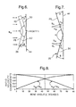
- Figure 6 is a schematic side view of the heater core;
- Figure 7 is a schematic side view of the heater core illustrating velocity components for the air;
- Figure 8 is a graph illustrating the relationships between various velocity components relative to various bend angles β of the heater core; and
- Figure 9 is a graph illustrating a temperature rise and a pressure drop for various bend angles β of the heater core.
-
- Referring to the Figures, wherein like numerals indicate like or corresponding parts throughout the several views, a heating, ventilating, and air conditioning (HVAC) assembly or module for heating, venting, and cooling a passenger compartment of a vehicle (not shown) is generally illustrated at 10 in Figures 1 and 2. The
HVAC module 10 includes ahollow housing 12 having aninlet 14 and at least oneoutlet outlets outlet 16, an upperpassenger compartment outlet 18, and a lowerpassenger compartment outlet 20. The upperpassenger compartment outlet 18 distributes air to an upper duct (not shown) which in turn transfers the air to passenger vents disposed along a dashboard (not shown). The lowerpassenger compartment outlet 20 distributes air to a lower duct (not shown) which in turn transfers the air to a floorboard or foot area vents (not shown). Arrows are provided to illustrate the flow of air through thehousing 12 and theoutlets housing 12 and location and number of outlets are well known to those skilled in the HVAC art and may be of any suitable design. - A
first heat exchanger 22 is disposed within thehousing 12 downstream of theinlet 14 and upstream from theoutlets first heat exchanger 22 is anevaporator core 22. Theevaporator core 22 is arranged and configured to intercept substantially all of the air flowing into the passenger compartment. Preferably, thehousing 12 includes an evaporatorcore mounting area 24 which is positioned adjacent theinlet 14 of thehousing 12. Theevaporator core 22 is secured to thehousing 12 in theevaporator core 22mounting area 24 and is large enough to completely extend across theinlet 14. Hence, air flowing from theinlet 14 toward theoutlets evaporator core 22. Theevaporator core 22 cools and dehumidifies the air flowing therethrough as is known in the HVAC art. It should also be appreciated that theevaporator core 22 may be of any suitable design or configuration without deviating from the scope of the subject invention. - A
second heat exchanger 26 is also disposed within thehousing 12 between theevaporator core 22 and theoutlets second heat exchanger 26 is aheater core 26 with theheater core 26 having anupstream surface 28 generally facing theevaporator core 22 and adownstream surface 30 generally facing theoutlet heater core 26 includesopposing manifolds 31 with a plurality offins 32 andtubes 33 extending along the length thereof between themanifolds 31.Inlet 35 andoutlet 37 ports are disposed on one or more of themanifolds 31 to transfer liquid through thetubes 33 between themanifolds 31 thereby facilitating the necessary heat transfer between the liquid and the air. Thefins 32,tubes 33, manifolds 31 and remaining portions of theheater core 26 are designed and configured in a manner known to those skilled in the heat exchanger arts. Further details of the preferredheater core 26 will be discussed in greater detail below. - The
housing 12 further includes anupper quadrant 34 and alower quadrant 36 with theevaporator core 22 disposed within both of the quadrants and theheater core 26 disposed within thelower quadrant 36. Hence, air flowing through theupper quadrant 34 will be for venting and cooling, and air flowing through thelower quadrant 36 will be for heating. - At least one, and preferably more than one,
flow valve 38 is disposed within thehousing 12 for controlling the flow of air between the upper 34 and lower 36 quadrants. Theflow valve 38 directs the flow of air such that heated, vented, and/or cooled air can be distributed through theoutlets - Referring also to Figures 3A - 5, the
heater core 26 is now discussed in greater detail. Theheater core 26 includes afirst portion 40 and asecond portion 42 being angled relative to thefirst portion 40. Preferably, theangled heater core 26 faces theevaporator core 22 such that theupstream surface 28 of thefirst portion 40 at least partially faces theupstream surface 28 of thesecond portion 42. Because of this angled feature, air flowing over theupstream surfaces 28 is more evenly distributed across both of the first 40 and second 42 portions, thereby increasing the effectiveness of theheater core 26, see Figure 5. In other words, the temperature increase across theheater core 26 is maximized and the pressure drop across theheater core 26 is minimized. - Each of the first 40 and second 42 portions preferably have a substantially flat rectangular configuration with a central region and a peripheral region. The central regions abut each other such that the first 40 and second 42 portions create a continuous
angled heater core 26. - The
heater cores 26 shown in the Figures have slightly different configurations. In particular, Figures 3A and 3B illustrate a first embodiment of theheater core 26 wherein thefins 32 andtubes 33 extend in a vertical direction when mounted in thehousing 12. Thefins 32 andtubes 33 are bent at the intersection of the central regions to define theangled heater core 26. Figures 4A and 4B illustrate a second embodiment of theheater core 26 wherein thefins 32 andtubes 33 extend in a horizontal direction when mounted in thehousing 12. In addition, thefins 32 can be spaced in a uniform or non-uniform manner. As best shown in Figures 1, 2, 3A, and 4A the plurality offins 32 are spaced apart in a non-uniform manner. In other words, thefins 32 are unequally spaced throughout at least one of the central and peripheral regions. Preferably, thefins 32 have a higher density in the central region of thefirst portion 40 where the incurring air flow rate is higher. Alternatively, thetubes 33 may be spaced apart in a non-uniform manner in conjunction with or instead of thefins 32. Hence, thetubes 33 and/orfins 32 are unequally spaced throughout at least one of the central and peripheral regions. As shown in Figure 3B and 4B, the plurality offins 32 andtubes 33 are alternatively spaced apart in a uniform manner. In other words, both thefins 32 andtubes 33 are equally spaced throughout the central and peripheral regions. - As illustrated in Figure 5, the air flow is concentrated most in the central region of the
first portion 40. Hence, the air velocity is greatest in this region. In order to capitalize on this increased velocity, thefins 32 are concentrated in this area. The remaining regions of the first 40 and second 42 portions havefins 32 that are spaced farther apart. The spacing offins 32 in the first 40 and second 42 portions controls the velocity of the air flowing through theheater core 26. As such, the increased velocity of the air passing through the central region of thefirst portion 40 is reduced more than the velocity of the air passing through the other regions of the first 40 and second 42 portions. This equates to having a more uniform exit velocity of the air. By taking advantage of the increased localized velocity of the air, the temperature increase across theheater core 26 can be maximized while the pressure drop across theheater core 26 can be minimized. - Referring also to Figures 6 and 7, preferably, the
first portion 40 is angled relative to thesecond portion 42 by more than 90 degrees. The angle between the first 40 and second 42 portions is illustrated in Figures 5 - 7, by the included angle α. Even more preferably, thefirst portion 40 is angled relative to thesecond portion 42 by an included angle α of 140 degrees. Specifically, thedownstream surface 30 of thefirst portion 40 is angled relative to the downstream portion of thesecond portion 42 by an included angle α of 140 degrees. - A bend angle β is also illustrated in Figures 5 - 7 wherein the bend angle β sets forth the angle of the
downstream surfaces 30 of the first 40 and second 42 portions relative to aplane 44. Theplane 44 is substantially perpendicular to a flow velocity of the air toward theheater core 26, see Figures 5 - 7. - The total velocity vector of the air toward the
heater core 26 is labeled as U∞. When the air hits theheater core 26, the velocity vector U∞ is split into two different velocity vectors Un and Up. Velocity vector un of the air is the normal component of the velocity vector U∞ relative to theheater core 26. Stated another way, the velocity vector Un denotes the velocity of air that is facing theupstream surface 28 of theheater core 26 and subsequently passes through theheater core 26 to exit out thedownstream surface 30 of theheater core 26. Velocity vector up of the air is the parallel component of the velocity vector U∞ relative to theheater core 26. In other words, velocity vector Up denotes the velocity of air that runs parallel along theupstream surface 28 of theheater core 26. This velocity component, Up, defines an inefficiency of theheater core 26 in that a portion of the total velocity of air U∞ is not passing through theheater core 26. Therefore, it is desirable to always have the velocity vector up be smaller than the velocity vector un. - The bend angle of the
heater core 26 directly affects the values of the velocity vectors un and up. Referring to Figure 8, the velocity vectors for up and un are illustrated as components of u∞. As illustrated, the optimum bend angle β, wherein the velocity vector un is larger than the velocity vector up, is less than 45 degrees. In other words, if the first 40 and second 42 portions of theheater core 26 were angled relative to theplane 44 by a bend angle β of more than 45 degrees, the velocity vector up would be larger than the velocity vector un, thereby creating aninefficient heater core 26. Stated another way, if thefirst portion 40 of theheater core 26 was angled relative to thesecond portion 42 of theheater core 26 by an included angle α of less than 90 degrees, the velocity vector up would be larger than the velocity vector un, thereby creating aninefficient heater core 26. Using the bend angle β, the preferred angular position of the first 40 and second 42 portions relative to theplane 44 is less than 45 degrees. - The bend angle of the
heater core 26 also directly affects the temperature increase values and the pressure drop values. Referring to Figure 9, the change in temperature and change in pressure are illustrated for various different bend angles of theheater core 26. As illustrated, the optimum bend angle β, wherein the temperature increase is maximized and the pressure drop is minimized, is 20 degrees. Hence, if the first 40 and second 42 portions of theheater core 26 were angled relative to theplane 44 by a bend angle β of significantly more or less than 20 degrees, the temperature increase will reduce and the pressure drop will become larger, thereby creating aninefficient heater core 26. Stated another way, if thefirst portion 40 of theheater core 26 was angled relative to thesecond portion 42 of theheater core 26 by an included angle α of significantly more or less than 140 degrees, the temperature increase will reduce and the pressure drop will become larger, thereby creating aninefficient heater core 26. - As appreciated, the preferred included angle α and bend angle β discussed above correlate to each other such that the combination of included angle α plus twice bend angle β equals 180 degrees. In addition, the preferred included angles α and bend angles β can change depending upon the type, design, and configuration of the
heater core 26. A method of ideally determining the included angle α and bend angle β for any heat exchanger is set forth in detail below. - As discussed above, the particular angle of the
first portion 40 relative to thesecond portion 42 is important to the performance of any heat exchanger, including theheater core 26 of the subject invention. If the relative angle between theportions heater core 26 will not operate at its full effectiveness, i.e., the temperature increase will not be maximized and the pressure drop will not be minimized. - Accordingly, the subject invention includes a method of optimizing the flow of air over the
heater core 26. The method comprising the step of calculating a variance between incoming and outgoing temperatures of the air to determine a temperature increase across theheater core 26. The method further comprises the step of calculating a variance between incoming and outgoing pressures of the air to determine a pressure drop across theheater core 26. The angular position thefirst portion 40 of theheater core 26 is then adjusted relative to thesecond portion 42 of theheater core 26 until the temperature increase across theheater core 26 is maximized and the pressure drop across theheater core 26 is minimized. This adjustment of the first 40 and second 42 portions thereby determines the optimum relative positions of the first 40 and second 42 portions for theangled heater core 26. - One method of calculating the temperature increase across the
heater core 26 includes measuring an incoming temperature of the air adjacent theupstream surface 28 of theheater core 26 and measuring an outgoing temperature of the air adjacent thedownstream surface 30 of theheater core 26. The outgoing temperature is then subtracted from the incoming temperature to determine the temperature increase. The measurements of the incoming and outgoing temperatures may be accomplished by any suitable device such as a temperature probe. Similarly, one method of calculating the pressure drop across theheater core 26 includes measuring an incoming pressure of the air adjacent theupstream surface 28 of theheater core 26 and measuring an outgoing pressure of the air adjacent thedownstream surface 30 of theheater core 26. The incoming pressure is then subtracted from the outgoing pressure to determine the pressure drop. The measurements of the incoming and outgoing pressures may be accomplished in any known manner such as utilizing a pressure probe. - Preferably, as discussed above, the step of adjusting the angular position the
first portion 40 relative to thesecond portion 42 is further defined as adjusting the first 40 and second 42 portions until thefirst portion 40 is angled relative to thesecond portion 42 by an included angle α of more than 90 degrees. More preferably, the step of adjusting the angular position of thefirst portion 40 relative to thesecond portion 42 is further defined as adjusting the first 40 and second 42 portions until thefirst portion 40 is angled relative to thesecond portion 42 by an included angle α of 140 degrees. Even more preferably, the step of adjusting the angular position of thefirst portion 40 relative to thesecond portion 42 is further defined as adjusting the first 40 and second 42 portions until thedownstream surface 30 of thefirst portion 40 is angled relative to the downstream portion of thesecond portion 42 by an included angle α of 140 degrees. - The step of calculating the temperature increase across the
heater core 26 may also be accomplished by utilizing the following formula;where, ΔTa is the temperature increase of the air across the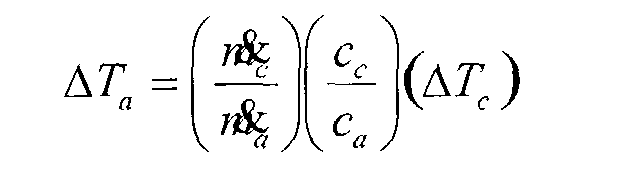
heater core 26,
is the mass flow rate of the air across the
heater core 26,
is the mass flow rate of the liquid flowing through the
heater core 26,
ca is the specific heat of the air,
Cc is the specific heat of the liquid passing through theheater core 26, and ΔTc is the temperature decrease of the liquid. - The step of calculating the temperature increase across the heater core is further defined as subtracting an inlet temperature of the liquid from an outlet temperature of the liquid to obtain the ΔTc temperature decrease. As discussed above, one or more of the
manifolds 31 include aninlet port 35 and/or anoutlet port 37 such that the inlet and outlet temperatures of the liquid can be measured. The above formula for calculating the temperature increase eliminates the need for a temperature probe disposed in the airflow path of the air. The mass flow rate of the airand the mass flow rate of the liquid are easily determined and the specific heat of the air ca and the specific heat of the liquid Cc are known constants. In addition, the temperature measurements of the liquid at the
inlet 35 andoutlet 37 ports can be easily determined. Hence, the above temperature formula simplifies the process for determining the temperature increase across theheater core 26. - The step of calculating the pressure drop across the
heater core 26 may also be accomplished by utilizing the following formula;where, ΔPa is the pressure drop of the air across the
heater core 26, - ƒ is a coefficient of friction within the
heater core 26, - λ is a depth or thickness of the
heater core 26, - is a mass flow rate of the air across the

heater core 26, - β is a bend angle the first 40 and second 42 portions relative to
a
plane 44 with theplane 44 being substantially perpendicular to a flow of the air toward theheater core 26, - ρa is a density of the air,
- gc is the constant of proportionality in Newton's second law of motion,
- dh is a hydraulic diameter of the flow passages through the
heater core,
and - A is a face area of the upstream surface of the heater core.
-
- The above formula for calculating the pressure drop eliminates the need for a pressure probe disposed in the airflow path of the air. The values for the coefficient of friction ƒ, depth of thickness λof the
heater core 26, mass flow rate of the airdensity of the air ρa, hydraulic diameter of the flow passages dh, and area A of the
upstream surface 28 are all known. The coefficient of friction or friction factor ƒ is dependent upon the airside fin configuration within theheater core 26. Hence, the friction factor ƒ for each of theheater cores 26 shown in Figures 3A - 4B will be different. The remaining value is to determine the bend angle β. As discussed above, the step of adjusting the angular position of thefirst portion 40 relative to thesecond portion 42 is further defined as adjusting the first 40 and second 42 portions until the bend angle β is less than 45 degrees. Even more preferably, the step of adjusting the angular position thefirst portion 40 relative to thesecond portion 42 is further defined as adjusting the first 40 and second 42 portions until the bend angle β is 20 degrees. Each of the values for the pressure formula set forth above are quickly determined such that this formula simplifies the process for determining the pressure drop across theheater core 26. - Obviously, many modifications and variations of the present invention are possible in light of the above teachings. The invention may be practiced otherwise than as specifically described within the scope of the appended claims, wherein the reference numerals in the claims are merely for convenience and are not to be read in any way as limiting.
Claims (25)
- A heating, ventilating, and air conditioning assembly (10) for heating, venting, and cooling a passenger compartment of a vehicle, said assembly comprising;said second heat exchanger (26) including a first portion (40) and a second portion (42) being angled relative to said first portion (40) such that said upstream surface (28) of said first portion (40) at least partially faces said upstream surface (28) of said second portion (42) to define an angled second heat exchanger (26) facing said first heat exchanger (22) wherein air flowing over said upstream surfaces (28) is evenly distributed across both of said first (40) and second (42) portions, thereby increasing the effectiveness of said second heat exchanger (26).a hollow housing (12) having an inlet (14) and at least one outlet (16,18,20) for directing a flow of air into the passenger compartment;a first heat exchanger (22) disposed within said housing (12) downstream of said inlet (14) and upstream from said outlet (16,18,20) with said first heat exchanger (22) arranged and configured for intercepting substantially all of the air flowing into the passenger compartment; anda second heat exchanger (26) disposed within said housing (12) between said first heat exchanger (22) and said outlet (16,18,20) with said second heat exchanger (26) having an upstream surface (28) generally facing said first heat exchanger (22) and a downstream surface (30) generally facing said outlet (16,18,20);
- An assembly as set forth in claim 1 wherein said first heat exchanger (22) is further defined as an evaporator core (22) and said second heat exchanger (26) is further defined as a heater core (26).
- An assembly as set forth in claim 1 wherein said first portion (40) is angled relative to said second portion (42) by more than 90 degrees.
- An assembly as set forth in claim 3 wherein said first portion (40) is angled relative to said second portion (42) by 140 degrees.
- An assembly as set forth in claim 4 wherein said downstream surface (30) of said first portion (40) is angled relative to said downstream portion of said second portion (42) by 140 degrees.
- An assembly as set forth in claim 5 wherein each of said first (40) and second (42) portions have a substantially flat rectangular configuration.
- An assembly as set forth in claim 2 wherein each of said first (40) and second (42) portions of said heater core (26) further include a plurality of fins (32) spaced apart in a uniform manner.
- An assembly as set forth in claim 2 wherein each of said first (40) and second (42) portions of said heater core (26) further include a plurality of fins (32) spaced apart in a non-uniform manner.
- An assembly as set forth in claim 8 wherein each of said first (40) and second (42) portions include a central region and a peripheral region with said central regions abutting each other, and said fins (32) of said first portion (40) having a higher concentration in said central region.
- An assembly as set forth in claim 2 wherein said housing (12) further includes an upper quadrant (34) and a lower quadrant (36) with said evaporator core (22) disposed within both of said quadrants (34,36) and said heater core (26) disposed within said lower quadrant (36).
- An assembly as set forth in claim 10 further including at least one flow valve (38) disposed within said housing (12) for controlling the flow of air between said upper (34) and lower (36) quadrants.
- An assembly as set forth in claim 10 wherein said housing (12) further includes three outlets (16,18,20) for distributing the flow of air throughout the passenger compartment.
- A method of optimizing a flow of air over a heater core (26) in a heating, ventilating, and air conditioning assembly (10) with the heater core (26) having an upstream surface (28) and a downstream surface (30) and the heater core (26) being divided into a first portion (40) and a second portion (42) angled relative to the first portion (40) such that the upstream surface (28) of the first portion (40) at least partially faces the upstream surface (28) of the second portion (42), thereby defining an angled heater core (26), said method comprising the steps of;
calculating a variance between incoming and outgoing temperatures of the air to determine a temperature increase across the heater core (26);
calculating a variance between incoming and outgoing pressures of the air to determine a pressure drop across the heater core (26); and
adjusting the angular position the first portion (40) of the heater core (26) relative to the second portion (42) of the heater core (26) until the temperature increase across the heater core (26) is maximized and the pressure drop across the heater core (26) is minimized, thereby determining the optimum relative positions of the first (40) and second (42) portions for the angled heater core (26). - A method as set forth in claim 13 wherein the step of calculating the temperature increase across the heater core (26) is further defined as measuring an incoming temperature of the air adjacent the upstream surface (28) of the heater core (26) and measuring an outgoing temperature of the air adjacent the downstream surface (30) of the heater core (26).
- A method as set forth in claim 14 wherein the step of calculating the temperature increase across the heater core (26) is further defined as subtracting the outgoing temperature from the incoming temperature.
- A method as set forth in claim 13 wherein the step of calculating the pressure drop across the heater core (26) is further defined as measuring an incoming pressure of the air adjacent the upstream surface (28) of the heater core (26) and measuring an outgoing pressure of the air adjacent the downstream surface (30) of the heater core (26).
- A method as set forth in claim 16 wherein the step of calculating the pressure drop across the heater core (26) is further defined as subtracting the incoming pressure from the outgoing pressure.
- A method as set forth in claim 13 wherein the step of calculating the temperature increase across the heater core (26) is further defined as calculating the temperature increase according to the following formula;where, ΔTa is the temperature increase of the air across the heater core (26),
 is the mass flow rate of the air across the heater core (26),
 is the mass flow rate of liquid flowing through the heater core (26),
 ca is a specific heat of the air,Cc is a specific heat of the liquid flowing through the heater core (26),
andΔTc is the temperature decrease of the liquid. - A method as set forth in claim 18 wherein the step of calculating the temperature increase across the heater core (26) is further defined as subtracting an inlet temperature of the liquid from an outlet temperature of the liquid to obtain the ΔTc temperature decrease.
- A method as set forth in claim 13 wherein the step of calculating the pressure drop across the heater core (26) is further defined as calculating the pressure drop according to the following formula; where, ΔPa is the pressure drop of the air across the heater core (26),
 ƒ is a coefficient of friction within the heater core (26),λ is a depth of the heater core (26),is a mass flow rate of the air across the heater core (26),
 β is a bend angle the first (40) and second (42) portions relative to a plane (44) with the plane (44) being substantially perpendicular to a flow of the air toward the heater core (26),ρa is a density of the air,gc is the constant of proportionality in Newton's second law of motion,dh is a hydraulic diameter of the flow passages through the heater core (26),
andA is a face area of the upstream surface (28) of the heater core (26). - A method as set forth in claim 20 wherein the step of adjusting the angular position of the first portion (40) relative to the second portion (42) is further defined as adjusting the first (40) and second (42) portions until the bend angle β is less than 45 degrees.
- A method as set forth in claim 21 wherein the step of adjusting the angular position of the first portion (40) relative to the second portion (42) is further defined as adjusting the first (40) and second (42) portions until the bend angle β is 20 degrees.
- A method as set forth in claim 13 wherein the step of adjusting the angular position of the first portion (40) relative to the second portion (42) is further defined as adjusting the first (40) and second (42) portions until the first portion (40) is angled relative to the second portion (42) by more than 90 degrees.
- A method as set forth in claim 23 wherein the step of adjusting the angular position of the first portion (40) relative to the second portion (42) is further defined as adjusting the first (40) and second (42) portions until the first portion (40) is angled relative to the second portion (42) by 140 degrees.
- A method as set forth in claim 24 wherein the step of adjusting the angular position of the first portion (40) relative to the second portion (42) is further defined as adjusting the first (40) and second (42) portions until the downstream surface (30) of the first portion (40) is angled relative to the downstream portion of the second portion (42) by 140 degrees.
Applications Claiming Priority (2)
| Application Number | Priority Date | Filing Date | Title |
|---|---|---|---|
| US179576 | 2002-06-25 | ||
| US10/179,576 US6880620B2 (en) | 2002-06-25 | 2002-06-25 | Heating, ventilating, and air conditioning module having an improved heater core configuration |
Publications (2)
| Publication Number | Publication Date |
|---|---|
| EP1375208A1 true EP1375208A1 (en) | 2004-01-02 |
| EP1375208B1 EP1375208B1 (en) | 2005-03-30 |
Family
ID=29717907
Family Applications (1)
| Application Number | Title | Priority Date | Filing Date |
|---|---|---|---|
| EP03076796A Expired - Lifetime EP1375208B1 (en) | 2002-06-25 | 2003-06-10 | Heating, ventilating and air conditioning module having an improved heater core configuration |
Country Status (3)
| Country | Link |
|---|---|
| US (1) | US6880620B2 (en) |
| EP (1) | EP1375208B1 (en) |
| DE (1) | DE60300442T2 (en) |
Cited By (4)
| Publication number | Priority date | Publication date | Assignee | Title |
|---|---|---|---|---|
| EP1596146A3 (en) * | 2004-05-10 | 2006-11-02 | Sanden Corporation | Heat exchangers and air conditioning systems including such heat exchangers |
| WO2008064251A3 (en) * | 2006-11-22 | 2008-10-09 | Johnson Controls Tech Co | Space-saving multichannel heat exchanger |
| WO2014059993A1 (en) * | 2012-10-16 | 2014-04-24 | Dantherm Air Handling A/S | Heat exchanger |
| US9783243B2 (en) | 2015-02-24 | 2017-10-10 | Illinois Tool Works Inc. | Sealing plug, assembly and method for sealing an opening |
Families Citing this family (19)
| Publication number | Priority date | Publication date | Assignee | Title |
|---|---|---|---|---|
| US20070169922A1 (en) * | 2006-01-24 | 2007-07-26 | Pautler Donald R | Microchannel, flat tube heat exchanger with bent tube configuration |
| US20070204977A1 (en) * | 2006-03-06 | 2007-09-06 | Henry Earl Beamer | Heat exchanger for stationary air conditioning system with improved water condensate drainage |
| US20070204978A1 (en) * | 2006-03-06 | 2007-09-06 | Henry Earl Beamer | Heat exchanger unit |
| US7699095B2 (en) | 2006-03-29 | 2010-04-20 | Delphi Technologies, Inc. | Bendable core unit |
| US20070289320A1 (en) * | 2006-06-15 | 2007-12-20 | Mohinder Singh Bhatti | Vapor compression AC system with evaporative cooler assisted evaporator |
| US20090188266A1 (en) * | 2008-01-29 | 2009-07-30 | Stephen Think Hung | Heating, ventilating, and air conditioning system having a thermal energy exchanger |
| US20090191804A1 (en) * | 2008-01-29 | 2009-07-30 | Lakhi Nandlal Goenka | Heating, ventilating, and air conditioning system having a thermal energy exchanger |
| CN101782337A (en) * | 2009-01-20 | 2010-07-21 | 三花丹佛斯(杭州)微通道换热器有限公司 | Micro-channel heat exchanger |
| US8721408B2 (en) * | 2009-11-18 | 2014-05-13 | Keihin Corporation | Air conditioner for vehicle |
| US20120227944A1 (en) * | 2011-03-10 | 2012-09-13 | Theodor Moisidis | Bent tube heat exchanger assembly |
| US9385382B2 (en) | 2013-06-10 | 2016-07-05 | GM Global Technology Operations LLC | Systems and methods for controlling cabin heating in fuel cell vehicles |
| US9724978B2 (en) * | 2015-04-14 | 2017-08-08 | Mahle International Gmbh | HVAC module having an open architecture |
| GB2546547A (en) * | 2016-01-22 | 2017-07-26 | Denso Marston Ltd | A heat exchanger system |
| DE102017101694A1 (en) | 2017-01-30 | 2018-08-02 | Voith Patent Gmbh | Cooling arrangement for a rail vehicle |
| JP7329373B2 (en) * | 2019-07-01 | 2023-08-18 | 三菱重工サーマルシステムズ株式会社 | Air Conditioning Units, Heat Exchangers, and Air Conditioners |
| US20210063089A1 (en) | 2019-09-03 | 2021-03-04 | Mahle International Gmbh | Curved heat exchanger and method of manufacturing |
| FR3115732B1 (en) * | 2020-11-04 | 2022-10-14 | Valeo Systemes Thermiques | Cooling module for electric or hybrid motor vehicle with tangential turbomachine with additional heat exchanger |
| CN117628672A (en) * | 2023-10-07 | 2024-03-01 | 青岛海尔空调器有限总公司 | Method, device and air conditioner for controlling air conditioner |
| FR3159663B1 (en) | 2024-02-26 | 2026-05-08 | Liebherr Aerospace Toulouse Sas | HEAT EXCHANGER COMPRISING A PLURALITY OF FLUID CIRCULATION PLATES EACH COMPRISING AT LEAST TWO DISTINCT PORTIONS, COOLING SYSTEM AND MANUFACTURING METHOD |
Citations (5)
| Publication number | Priority date | Publication date | Assignee | Title |
|---|---|---|---|---|
| DE3814086A1 (en) * | 1987-04-28 | 1988-11-10 | Avl Verbrennungskraft Messtech | Heat exchanger system having a cross-flow blower |
| DE4227565C1 (en) * | 1992-08-20 | 1993-11-04 | Daimler Benz Ag | HEAT EXCHANGER IN A MOTOR VEHICLE |
| DE19641642A1 (en) * | 1995-10-20 | 1997-04-24 | Carrier Corp | Roof-mounted air conditioning unit |
| US5927380A (en) * | 1998-01-12 | 1999-07-27 | General Motors Corporation | Automotive heating, air conditioning and ventilation system with combined mode door and dual temperature sensor |
| US6045444A (en) * | 1998-08-28 | 2000-04-04 | General Motors Corporation | Compact automotive air conditioning module |
Family Cites Families (23)
| Publication number | Priority date | Publication date | Assignee | Title |
|---|---|---|---|---|
| US3545224A (en) * | 1968-12-18 | 1970-12-08 | Trane Co | Heat pump apparatus |
| DE3118539A1 (en) * | 1981-05-09 | 1982-12-02 | M.A.N. Maschinenfabrik Augsburg-Nürnberg AG, 8000 München | Engine cooling system on vehicles, especially motor vehicles |
| DE3344212A1 (en) * | 1983-12-07 | 1985-09-05 | Konvekta GmbH, 3578 Schwalmstadt | Device for air-conditioning the passenger compartment of a motor vehicle |
| DE3533196A1 (en) * | 1985-09-18 | 1987-03-26 | Sueddeutsche Kuehler Behr | Double heat exchanger, especially a heating element for a heating or air-conditioning system of a motor vehicle |
| FR2594757B1 (en) * | 1986-02-27 | 1990-09-28 | Valeo | ARRANGEMENT OF HEAT EXCHANGERS IN FRONT OF THE BODY OF A MOTOR VEHICLE |
| US4958500A (en) * | 1989-04-20 | 1990-09-25 | Hitachi, Ltd. | Air conditioner and air conditioning method |
| JPH04316931A (en) * | 1991-04-12 | 1992-11-09 | Toshiba Corp | Manufacture of heat exchanger and air conditioner equipped with the exchanger |
| US5335718A (en) | 1992-04-02 | 1994-08-09 | Ford Motor Company | Space-efficient air conditioning/heating module |
| GB2270154B (en) | 1992-08-26 | 1996-08-28 | Toshiba Kk | Air conditioner |
| JPH0755184A (en) | 1993-08-06 | 1995-03-03 | Fujitsu General Ltd | Air conditioner indoor unit |
| JP3514518B2 (en) | 1993-09-29 | 2004-03-31 | 三菱電機株式会社 | Separable air conditioner |
| DE19602805B4 (en) | 1995-02-01 | 2004-07-15 | Denso Corp., Kariya | Method for controlling a vehicle air conditioning system |
| US5669229A (en) | 1995-05-30 | 1997-09-23 | Mitsubishi Jukogyo Kabushiki Kaisha | Ceiling-mounted type air conditioner |
| JPH08327137A (en) * | 1995-05-30 | 1996-12-13 | Mitsubishi Heavy Ind Ltd | Ceiling-suspended air conditioner |
| JPH0942697A (en) * | 1995-07-27 | 1997-02-14 | Nippon Light Metal Co Ltd | Heat exchanger |
| JPH09226350A (en) | 1996-02-28 | 1997-09-02 | Calsonic Corp | Heater unit for vehicle air conditioner |
| JP3607007B2 (en) * | 1996-07-03 | 2005-01-05 | サンデン株式会社 | Air conditioner |
| JPH1061438A (en) * | 1996-08-20 | 1998-03-03 | Suzuki Motor Corp | Heat exchanger |
| JPH1058961A (en) * | 1996-08-22 | 1998-03-03 | Zexel Corp | Vehicle air conditioner |
| KR100214639B1 (en) | 1996-12-21 | 1999-08-02 | 구자홍 | Top suction cross flow type indoor unit of air conditioner |
| DE19743656C2 (en) * | 1997-10-02 | 2000-02-17 | Behr Gmbh & Co | Heating or air conditioning for a motor vehicle |
| US5934361A (en) | 1998-02-27 | 1999-08-10 | General Motors Corporation | Automotive heating and air conditioning assembly with improved air flow and temperature control |
| JP2001183000A (en) * | 1999-12-24 | 2001-07-06 | Sanyo Electric Co Ltd | Air conditioner |
-
2002
- 2002-06-25 US US10/179,576 patent/US6880620B2/en not_active Expired - Lifetime
-
2003
- 2003-06-10 DE DE60300442T patent/DE60300442T2/en not_active Expired - Lifetime
- 2003-06-10 EP EP03076796A patent/EP1375208B1/en not_active Expired - Lifetime
Patent Citations (5)
| Publication number | Priority date | Publication date | Assignee | Title |
|---|---|---|---|---|
| DE3814086A1 (en) * | 1987-04-28 | 1988-11-10 | Avl Verbrennungskraft Messtech | Heat exchanger system having a cross-flow blower |
| DE4227565C1 (en) * | 1992-08-20 | 1993-11-04 | Daimler Benz Ag | HEAT EXCHANGER IN A MOTOR VEHICLE |
| DE19641642A1 (en) * | 1995-10-20 | 1997-04-24 | Carrier Corp | Roof-mounted air conditioning unit |
| US5927380A (en) * | 1998-01-12 | 1999-07-27 | General Motors Corporation | Automotive heating, air conditioning and ventilation system with combined mode door and dual temperature sensor |
| US6045444A (en) * | 1998-08-28 | 2000-04-04 | General Motors Corporation | Compact automotive air conditioning module |
Cited By (4)
| Publication number | Priority date | Publication date | Assignee | Title |
|---|---|---|---|---|
| EP1596146A3 (en) * | 2004-05-10 | 2006-11-02 | Sanden Corporation | Heat exchangers and air conditioning systems including such heat exchangers |
| WO2008064251A3 (en) * | 2006-11-22 | 2008-10-09 | Johnson Controls Tech Co | Space-saving multichannel heat exchanger |
| WO2014059993A1 (en) * | 2012-10-16 | 2014-04-24 | Dantherm Air Handling A/S | Heat exchanger |
| US9783243B2 (en) | 2015-02-24 | 2017-10-10 | Illinois Tool Works Inc. | Sealing plug, assembly and method for sealing an opening |
Also Published As
| Publication number | Publication date |
|---|---|
| DE60300442T2 (en) | 2005-09-22 |
| DE60300442D1 (en) | 2005-05-04 |
| EP1375208B1 (en) | 2005-03-30 |
| US6880620B2 (en) | 2005-04-19 |
| US20030234098A1 (en) | 2003-12-25 |
Similar Documents
| Publication | Publication Date | Title |
|---|---|---|
| EP1375208B1 (en) | Heating, ventilating and air conditioning module having an improved heater core configuration | |
| US5311935A (en) | Corrugated fin type heat exchanger | |
| US6308770B1 (en) | Air conditioning apparatus | |
| US6834709B2 (en) | Automotive air conditioner | |
| US5209285A (en) | Inclined tube radiator | |
| US9115934B2 (en) | Heat exchanger flow limiting baffle | |
| CN107709090A (en) | Neck fan for vehicle seat and method for adjusting same | |
| KR100443392B1 (en) | Automotive air conditioner | |
| CN101121375A (en) | Vehicle Air Conditioning System | |
| JP4821034B2 (en) | Air conditioning unit for vehicles | |
| US7370691B2 (en) | Heat exchanger and heating or air conditioning unit of a motor vehicle containing said heat exchanger | |
| US6651453B2 (en) | Air-conditioning device for a motor vehicle | |
| CA3052746C (en) | Pneumatic radiation air conditioner | |
| JPH07149135A (en) | Air conditioner for vehicle | |
| US12104819B2 (en) | Air-conditioning unit, heat exchanger, and air conditioner | |
| JPH109777A (en) | Multi-tube heat exchangers and air conditioners | |
| US20260097622A1 (en) | Heating, ventilation, and air conditioning system | |
| JP3018385B2 (en) | Automotive air conditioners | |
| EP3894774B1 (en) | Air conditioning system provided with a droplet separator, in particular for a motor vehicle | |
| JP3277772B2 (en) | Heat Exchanger for Air Conditioning and Air Conditioner for Automobile | |
| KR101236717B1 (en) | Combination structure of water temp sensor forair conditioner | |
| KR102512379B1 (en) | Air conditioner for vehicle | |
| JP2001163036A (en) | Hot water heating system | |
| KR20060015962A (en) | Evaporator and vehicle air conditioner | |
| KR19980034438U (en) | heat transmitter |
Legal Events
| Date | Code | Title | Description |
|---|---|---|---|
| PUAI | Public reference made under article 153(3) epc to a published international application that has entered the european phase |
Free format text: ORIGINAL CODE: 0009012 |
|
| AK | Designated contracting states |
Kind code of ref document: A1 Designated state(s): AT BE BG CH CY CZ DE DK EE ES FI FR GB GR HU IE IT LI LU MC NL PT RO SE SI SK TR |
|
| AX | Request for extension of the european patent |
Extension state: AL LT LV MK |
|
| GRAP | Despatch of communication of intention to grant a patent |
Free format text: ORIGINAL CODE: EPIDOSNIGR1 |
|
| 17P | Request for examination filed |
Effective date: 20040702 |
|
| AKX | Designation fees paid |
Designated state(s): DE FR GB |
|
| GRAS | Grant fee paid |
Free format text: ORIGINAL CODE: EPIDOSNIGR3 |
|
| GRAA | (expected) grant |
Free format text: ORIGINAL CODE: 0009210 |
|
| AK | Designated contracting states |
Kind code of ref document: B1 Designated state(s): DE FR GB |
|
| REG | Reference to a national code |
Ref country code: GB Ref legal event code: FG4D |
|
| REF | Corresponds to: |
Ref document number: 60300442 Country of ref document: DE Date of ref document: 20050504 Kind code of ref document: P |
|
| REG | Reference to a national code |
Ref country code: IE Ref legal event code: FG4D |
|
| ET | Fr: translation filed | ||
| PLBE | No opposition filed within time limit |
Free format text: ORIGINAL CODE: 0009261 |
|
| STAA | Information on the status of an ep patent application or granted ep patent |
Free format text: STATUS: NO OPPOSITION FILED WITHIN TIME LIMIT |
|
| 26N | No opposition filed |
Effective date: 20060102 |
|
| GBPC | Gb: european patent ceased through non-payment of renewal fee |
Effective date: 20070610 |
|
| PG25 | Lapsed in a contracting state [announced via postgrant information from national office to epo] |
Ref country code: GB Free format text: LAPSE BECAUSE OF NON-PAYMENT OF DUE FEES Effective date: 20070610 |
|
| REG | Reference to a national code |
Ref country code: DE Ref legal event code: R082 Ref document number: 60300442 Country of ref document: DE Representative=s name: BRP RENAUD UND PARTNER MBB RECHTSANWAELTE PATE, DE Ref country code: DE Ref legal event code: R082 Ref document number: 60300442 Country of ref document: DE Representative=s name: BRP RENAUD UND PARTNER MBB, DE Ref country code: DE Ref legal event code: R081 Ref document number: 60300442 Country of ref document: DE Owner name: MAHLE INTERNATIONAL GMBH, DE Free format text: FORMER OWNER: DELPHI TECHNOLOGIES, INC., TROY, MICH., US |
|
| REG | Reference to a national code |
Ref country code: FR Ref legal event code: PLFP Year of fee payment: 14 |
|
| REG | Reference to a national code |
Ref country code: FR Ref legal event code: PLFP Year of fee payment: 15 |
|
| REG | Reference to a national code |
Ref country code: FR Ref legal event code: TP Owner name: MAHLE INTERNATIONAL GMBH, DE Effective date: 20180103 |
|
| REG | Reference to a national code |
Ref country code: FR Ref legal event code: PLFP Year of fee payment: 16 |
|
| PGFP | Annual fee paid to national office [announced via postgrant information from national office to epo] |
Ref country code: FR Payment date: 20180629 Year of fee payment: 16 |
|
| PGFP | Annual fee paid to national office [announced via postgrant information from national office to epo] |
Ref country code: DE Payment date: 20180831 Year of fee payment: 16 |
|
| REG | Reference to a national code |
Ref country code: DE Ref legal event code: R119 Ref document number: 60300442 Country of ref document: DE |
|
| PG25 | Lapsed in a contracting state [announced via postgrant information from national office to epo] |
Ref country code: DE Free format text: LAPSE BECAUSE OF NON-PAYMENT OF DUE FEES Effective date: 20200101 |
|
| PG25 | Lapsed in a contracting state [announced via postgrant information from national office to epo] |
Ref country code: FR Free format text: LAPSE BECAUSE OF NON-PAYMENT OF DUE FEES Effective date: 20190630 |