EP1375172B1 - Thermal transfer recording web roll - Google Patents
Thermal transfer recording web roll Download PDFInfo
- Publication number
- EP1375172B1 EP1375172B1 EP03013450A EP03013450A EP1375172B1 EP 1375172 B1 EP1375172 B1 EP 1375172B1 EP 03013450 A EP03013450 A EP 03013450A EP 03013450 A EP03013450 A EP 03013450A EP 1375172 B1 EP1375172 B1 EP 1375172B1
- Authority
- EP
- European Patent Office
- Prior art keywords
- thermal transfer
- transfer recording
- recording web
- web roll
- web
- Prior art date
- Legal status (The legal status is an assumption and is not a legal conclusion. Google has not performed a legal analysis and makes no representation as to the accuracy of the status listed.)
- Expired - Lifetime
Links
- 238000012546 transfer Methods 0.000 title claims description 294
- 239000010410 layer Substances 0.000 claims description 107
- 238000004804 winding Methods 0.000 claims description 20
- 239000012790 adhesive layer Substances 0.000 claims description 18
- 239000000853 adhesive Substances 0.000 claims description 6
- 230000001070 adhesive effect Effects 0.000 claims description 6
- 229920005989 resin Polymers 0.000 description 55
- 239000011347 resin Substances 0.000 description 55
- 238000000034 method Methods 0.000 description 32
- 239000000123 paper Substances 0.000 description 24
- 230000008569 process Effects 0.000 description 16
- 238000000576 coating method Methods 0.000 description 13
- 230000000694 effects Effects 0.000 description 13
- 239000011247 coating layer Substances 0.000 description 10
- 239000011248 coating agent Substances 0.000 description 9
- 229920003023 plastic Polymers 0.000 description 9
- 239000004033 plastic Substances 0.000 description 9
- 239000003795 chemical substances by application Substances 0.000 description 8
- 239000000975 dye Substances 0.000 description 8
- 239000000314 lubricant Substances 0.000 description 8
- 239000011230 binding agent Substances 0.000 description 7
- 239000000463 material Substances 0.000 description 7
- -1 polypropylene Polymers 0.000 description 7
- 239000004925 Acrylic resin Substances 0.000 description 6
- 239000007788 liquid Substances 0.000 description 6
- 238000011068 loading method Methods 0.000 description 6
- 239000000203 mixture Substances 0.000 description 6
- 229920000178 Acrylic resin Polymers 0.000 description 5
- 239000000945 filler Substances 0.000 description 5
- 238000005096 rolling process Methods 0.000 description 5
- 229920002554 vinyl polymer Polymers 0.000 description 5
- VYPSYNLAJGMNEJ-UHFFFAOYSA-N Silicium dioxide Chemical compound O=[Si]=O VYPSYNLAJGMNEJ-UHFFFAOYSA-N 0.000 description 4
- 239000000654 additive Substances 0.000 description 4
- 239000001913 cellulose Substances 0.000 description 4
- 229920002678 cellulose Polymers 0.000 description 4
- 239000012461 cellulose resin Substances 0.000 description 4
- 238000001035 drying Methods 0.000 description 4
- 229920005668 polycarbonate resin Polymers 0.000 description 4
- 239000004431 polycarbonate resin Substances 0.000 description 4
- 229920001225 polyester resin Polymers 0.000 description 4
- 239000004645 polyester resin Substances 0.000 description 4
- 229920005749 polyurethane resin Polymers 0.000 description 4
- 238000007763 reverse roll coating Methods 0.000 description 4
- 238000007650 screen-printing Methods 0.000 description 4
- 229920002545 silicone oil Polymers 0.000 description 4
- 239000002699 waste material Substances 0.000 description 4
- 239000012463 white pigment Substances 0.000 description 4
- ZWEHNKRNPOVVGH-UHFFFAOYSA-N 2-Butanone Chemical compound CCC(C)=O ZWEHNKRNPOVVGH-UHFFFAOYSA-N 0.000 description 3
- XEKOWRVHYACXOJ-UHFFFAOYSA-N Ethyl acetate Chemical compound CCOC(C)=O XEKOWRVHYACXOJ-UHFFFAOYSA-N 0.000 description 3
- 239000004743 Polypropylene Substances 0.000 description 3
- YXFVVABEGXRONW-UHFFFAOYSA-N Toluene Chemical compound CC1=CC=CC=C1 YXFVVABEGXRONW-UHFFFAOYSA-N 0.000 description 3
- 239000011354 acetal resin Substances 0.000 description 3
- 229920001577 copolymer Polymers 0.000 description 3
- 239000012634 fragment Substances 0.000 description 3
- 238000007646 gravure printing Methods 0.000 description 3
- 238000010030 laminating Methods 0.000 description 3
- 239000000155 melt Substances 0.000 description 3
- 238000012986 modification Methods 0.000 description 3
- 230000004048 modification Effects 0.000 description 3
- 229920001778 nylon Polymers 0.000 description 3
- 229920006122 polyamide resin Polymers 0.000 description 3
- 229920005672 polyolefin resin Polymers 0.000 description 3
- 229920006324 polyoxymethylene Polymers 0.000 description 3
- 229920001155 polypropylene Polymers 0.000 description 3
- 229920005990 polystyrene resin Polymers 0.000 description 3
- 238000000859 sublimation Methods 0.000 description 3
- 230000008022 sublimation Effects 0.000 description 3
- 238000010023 transfer printing Methods 0.000 description 3
- VTYYLEPIZMXCLO-UHFFFAOYSA-L Calcium carbonate Chemical compound [Ca+2].[O-]C([O-])=O VTYYLEPIZMXCLO-UHFFFAOYSA-L 0.000 description 2
- RTZKZFJDLAIYFH-UHFFFAOYSA-N Diethyl ether Chemical compound CCOCC RTZKZFJDLAIYFH-UHFFFAOYSA-N 0.000 description 2
- UFHFLCQGNIYNRP-UHFFFAOYSA-N Hydrogen Chemical compound [H][H] UFHFLCQGNIYNRP-UHFFFAOYSA-N 0.000 description 2
- 229920000877 Melamine resin Polymers 0.000 description 2
- 239000004372 Polyvinyl alcohol Substances 0.000 description 2
- 229920001328 Polyvinylidene chloride Polymers 0.000 description 2
- PPBRXRYQALVLMV-UHFFFAOYSA-N Styrene Chemical compound C=CC1=CC=CC=C1 PPBRXRYQALVLMV-UHFFFAOYSA-N 0.000 description 2
- 229920001807 Urea-formaldehyde Polymers 0.000 description 2
- XLOMVQKBTHCTTD-UHFFFAOYSA-N Zinc monoxide Chemical compound [Zn]=O XLOMVQKBTHCTTD-UHFFFAOYSA-N 0.000 description 2
- 239000002390 adhesive tape Substances 0.000 description 2
- 230000002411 adverse Effects 0.000 description 2
- 238000013459 approach Methods 0.000 description 2
- TZCXTZWJZNENPQ-UHFFFAOYSA-L barium sulfate Chemical compound [Ba+2].[O-]S([O-])(=O)=O TZCXTZWJZNENPQ-UHFFFAOYSA-L 0.000 description 2
- 230000015572 biosynthetic process Effects 0.000 description 2
- QHIWVLPBUQWDMQ-UHFFFAOYSA-N butyl prop-2-enoate;methyl 2-methylprop-2-enoate;prop-2-enoic acid Chemical compound OC(=O)C=C.COC(=O)C(C)=C.CCCCOC(=O)C=C QHIWVLPBUQWDMQ-UHFFFAOYSA-N 0.000 description 2
- 230000008859 change Effects 0.000 description 2
- 238000004132 cross linking Methods 0.000 description 2
- JHIVVAPYMSGYDF-UHFFFAOYSA-N cyclohexanone Chemical compound O=C1CCCCC1 JHIVVAPYMSGYDF-UHFFFAOYSA-N 0.000 description 2
- 238000001514 detection method Methods 0.000 description 2
- 239000001257 hydrogen Substances 0.000 description 2
- 229910052739 hydrogen Inorganic materials 0.000 description 2
- 239000011256 inorganic filler Substances 0.000 description 2
- 229910003475 inorganic filler Inorganic materials 0.000 description 2
- 238000004519 manufacturing process Methods 0.000 description 2
- 230000007246 mechanism Effects 0.000 description 2
- 238000002156 mixing Methods 0.000 description 2
- 239000012766 organic filler Substances 0.000 description 2
- 239000003960 organic solvent Substances 0.000 description 2
- 239000000049 pigment Substances 0.000 description 2
- 229920001200 poly(ethylene-vinyl acetate) Polymers 0.000 description 2
- 229920002037 poly(vinyl butyral) polymer Polymers 0.000 description 2
- 229920000058 polyacrylate Polymers 0.000 description 2
- 229920000642 polymer Polymers 0.000 description 2
- 229920002451 polyvinyl alcohol Polymers 0.000 description 2
- 239000004800 polyvinyl chloride Substances 0.000 description 2
- 229920000915 polyvinyl chloride Polymers 0.000 description 2
- 239000005033 polyvinylidene chloride Substances 0.000 description 2
- 239000000843 powder Substances 0.000 description 2
- 238000007639 printing Methods 0.000 description 2
- 150000003242 quaternary ammonium salts Chemical class 0.000 description 2
- 230000009467 reduction Effects 0.000 description 2
- 238000007789 sealing Methods 0.000 description 2
- 239000000377 silicon dioxide Substances 0.000 description 2
- 239000002904 solvent Substances 0.000 description 2
- 238000003892 spreading Methods 0.000 description 2
- 230000007480 spreading Effects 0.000 description 2
- 229920003002 synthetic resin Polymers 0.000 description 2
- 239000000057 synthetic resin Substances 0.000 description 2
- 125000000391 vinyl group Chemical group [H]C([*])=C([H])[H] 0.000 description 2
- PEVRKKOYEFPFMN-UHFFFAOYSA-N 1,1,2,3,3,3-hexafluoroprop-1-ene;1,1,2,2-tetrafluoroethene Chemical group FC(F)=C(F)F.FC(F)=C(F)C(F)(F)F PEVRKKOYEFPFMN-UHFFFAOYSA-N 0.000 description 1
- DHKHKXVYLBGOIT-UHFFFAOYSA-N 1,1-Diethoxyethane Chemical compound CCOC(C)OCC DHKHKXVYLBGOIT-UHFFFAOYSA-N 0.000 description 1
- GZVHEAJQGPRDLQ-UHFFFAOYSA-N 6-phenyl-1,3,5-triazine-2,4-diamine Chemical compound NC1=NC(N)=NC(C=2C=CC=CC=2)=N1 GZVHEAJQGPRDLQ-UHFFFAOYSA-N 0.000 description 1
- 239000005995 Aluminium silicate Substances 0.000 description 1
- KWIUHFFTVRNATP-UHFFFAOYSA-N Betaine Natural products C[N+](C)(C)CC([O-])=O KWIUHFFTVRNATP-UHFFFAOYSA-N 0.000 description 1
- LSNNMFCWUKXFEE-UHFFFAOYSA-M Bisulfite Chemical compound OS([O-])=O LSNNMFCWUKXFEE-UHFFFAOYSA-M 0.000 description 1
- 239000005977 Ethylene Substances 0.000 description 1
- IAYPIBMASNFSPL-UHFFFAOYSA-N Ethylene oxide Chemical compound C1CO1 IAYPIBMASNFSPL-UHFFFAOYSA-N 0.000 description 1
- 239000004606 Fillers/Extenders Substances 0.000 description 1
- YCKRFDGAMUMZLT-UHFFFAOYSA-N Fluorine atom Chemical compound [F] YCKRFDGAMUMZLT-UHFFFAOYSA-N 0.000 description 1
- KWIUHFFTVRNATP-UHFFFAOYSA-O N,N,N-trimethylglycinium Chemical compound C[N+](C)(C)CC(O)=O KWIUHFFTVRNATP-UHFFFAOYSA-O 0.000 description 1
- WHNWPMSKXPGLAX-UHFFFAOYSA-N N-Vinyl-2-pyrrolidone Chemical compound C=CN1CCCC1=O WHNWPMSKXPGLAX-UHFFFAOYSA-N 0.000 description 1
- 239000004677 Nylon Substances 0.000 description 1
- CTQNGGLPUBDAKN-UHFFFAOYSA-N O-Xylene Chemical compound CC1=CC=CC=C1C CTQNGGLPUBDAKN-UHFFFAOYSA-N 0.000 description 1
- 229910019142 PO4 Inorganic materials 0.000 description 1
- 239000002033 PVDF binder Substances 0.000 description 1
- 239000004696 Poly ether ether ketone Substances 0.000 description 1
- 239000004695 Polyether sulfone Substances 0.000 description 1
- 239000004697 Polyetherimide Substances 0.000 description 1
- 239000004698 Polyethylene Substances 0.000 description 1
- 239000004793 Polystyrene Substances 0.000 description 1
- 229920001131 Pulp (paper) Polymers 0.000 description 1
- QAOWNCQODCNURD-UHFFFAOYSA-L Sulfate Chemical compound [O-]S([O-])(=O)=O QAOWNCQODCNURD-UHFFFAOYSA-L 0.000 description 1
- 229920006362 Teflon® Polymers 0.000 description 1
- GWEVSGVZZGPLCZ-UHFFFAOYSA-N Titan oxide Chemical compound O=[Ti]=O GWEVSGVZZGPLCZ-UHFFFAOYSA-N 0.000 description 1
- 238000005299 abrasion Methods 0.000 description 1
- NIXOWILDQLNWCW-UHFFFAOYSA-N acrylic acid group Chemical group C(C=C)(=O)O NIXOWILDQLNWCW-UHFFFAOYSA-N 0.000 description 1
- 239000004840 adhesive resin Substances 0.000 description 1
- 229920006223 adhesive resin Polymers 0.000 description 1
- PNEYBMLMFCGWSK-UHFFFAOYSA-N aluminium oxide Inorganic materials [O-2].[O-2].[O-2].[Al+3].[Al+3] PNEYBMLMFCGWSK-UHFFFAOYSA-N 0.000 description 1
- 235000012211 aluminium silicate Nutrition 0.000 description 1
- 150000001408 amides Chemical class 0.000 description 1
- 150000001413 amino acids Chemical class 0.000 description 1
- 229960003237 betaine Drugs 0.000 description 1
- 229910000019 calcium carbonate Inorganic materials 0.000 description 1
- 125000003178 carboxy group Chemical group [H]OC(*)=O 0.000 description 1
- 239000011111 cardboard Substances 0.000 description 1
- 239000003054 catalyst Substances 0.000 description 1
- 229920002301 cellulose acetate Polymers 0.000 description 1
- 238000006243 chemical reaction Methods 0.000 description 1
- 239000004927 clay Substances 0.000 description 1
- 229910052570 clay Inorganic materials 0.000 description 1
- 239000003086 colorant Substances 0.000 description 1
- 238000004040 coloring Methods 0.000 description 1
- 238000010276 construction Methods 0.000 description 1
- 238000007334 copolymerization reaction Methods 0.000 description 1
- 238000003851 corona treatment Methods 0.000 description 1
- 230000007423 decrease Effects 0.000 description 1
- 230000001419 dependent effect Effects 0.000 description 1
- 230000002542 deteriorative effect Effects 0.000 description 1
- 239000003085 diluting agent Substances 0.000 description 1
- 208000028659 discharge Diseases 0.000 description 1
- 239000000839 emulsion Substances 0.000 description 1
- 230000007613 environmental effect Effects 0.000 description 1
- 239000003822 epoxy resin Substances 0.000 description 1
- 150000002194 fatty esters Chemical class 0.000 description 1
- 229910052731 fluorine Inorganic materials 0.000 description 1
- 239000011737 fluorine Substances 0.000 description 1
- 150000002222 fluorine compounds Chemical class 0.000 description 1
- 239000006260 foam Substances 0.000 description 1
- 239000011086 glassine Substances 0.000 description 1
- 238000007756 gravure coating Methods 0.000 description 1
- LNEPOXFFQSENCJ-UHFFFAOYSA-N haloperidol Chemical compound C1CC(O)(C=2C=CC(Cl)=CC=2)CCN1CCCC(=O)C1=CC=C(F)C=C1 LNEPOXFFQSENCJ-UHFFFAOYSA-N 0.000 description 1
- 125000002887 hydroxy group Chemical group [H]O* 0.000 description 1
- 239000001023 inorganic pigment Substances 0.000 description 1
- 238000003780 insertion Methods 0.000 description 1
- 230000037431 insertion Effects 0.000 description 1
- 229920000554 ionomer Polymers 0.000 description 1
- 239000012948 isocyanate Substances 0.000 description 1
- NLYAJNPCOHFWQQ-UHFFFAOYSA-N kaolin Chemical compound O.O.O=[Al]O[Si](=O)O[Si](=O)O[Al]=O NLYAJNPCOHFWQQ-UHFFFAOYSA-N 0.000 description 1
- 238000004898 kneading Methods 0.000 description 1
- ZLNQQNXFFQJAID-UHFFFAOYSA-L magnesium carbonate Chemical compound [Mg+2].[O-]C([O-])=O ZLNQQNXFFQJAID-UHFFFAOYSA-L 0.000 description 1
- 239000001095 magnesium carbonate Substances 0.000 description 1
- 229910000021 magnesium carbonate Inorganic materials 0.000 description 1
- 229910044991 metal oxide Inorganic materials 0.000 description 1
- 150000004706 metal oxides Chemical class 0.000 description 1
- 150000002902 organometallic compounds Chemical class 0.000 description 1
- 239000011088 parchment paper Substances 0.000 description 1
- NBIIXXVUZAFLBC-UHFFFAOYSA-K phosphate Chemical compound [O-]P([O-])([O-])=O NBIIXXVUZAFLBC-UHFFFAOYSA-K 0.000 description 1
- 239000010452 phosphate Substances 0.000 description 1
- 239000002985 plastic film Substances 0.000 description 1
- 229920006255 plastic film Polymers 0.000 description 1
- 229920002493 poly(chlorotrifluoroethylene) Polymers 0.000 description 1
- 229920002492 poly(sulfone) Polymers 0.000 description 1
- 239000005023 polychlorotrifluoroethylene (PCTFE) polymer Substances 0.000 description 1
- 229920000647 polyepoxide Polymers 0.000 description 1
- 229920006393 polyether sulfone Polymers 0.000 description 1
- 229920002530 polyetherether ketone Polymers 0.000 description 1
- 229920001601 polyetherimide Polymers 0.000 description 1
- 229920000573 polyethylene Polymers 0.000 description 1
- 229920013716 polyethylene resin Polymers 0.000 description 1
- 229920001721 polyimide Polymers 0.000 description 1
- 239000009719 polyimide resin Substances 0.000 description 1
- 229920000306 polymethylpentene Polymers 0.000 description 1
- 239000011116 polymethylpentene Substances 0.000 description 1
- 229920000098 polyolefin Polymers 0.000 description 1
- 229920002223 polystyrene Polymers 0.000 description 1
- 239000011118 polyvinyl acetate Substances 0.000 description 1
- 229920002689 polyvinyl acetate Polymers 0.000 description 1
- 229920002620 polyvinyl fluoride Polymers 0.000 description 1
- 229920002981 polyvinylidene fluoride Polymers 0.000 description 1
- 125000002924 primary amino group Chemical group [H]N([H])* 0.000 description 1
- 229920006395 saturated elastomer Polymers 0.000 description 1
- 230000035945 sensitivity Effects 0.000 description 1
- 238000000926 separation method Methods 0.000 description 1
- 230000035939 shock Effects 0.000 description 1
- 150000003377 silicon compounds Chemical class 0.000 description 1
- 235000012239 silicon dioxide Nutrition 0.000 description 1
- 229920002050 silicone resin Polymers 0.000 description 1
- 238000004513 sizing Methods 0.000 description 1
- 239000007787 solid Substances 0.000 description 1
- 238000005507 spraying Methods 0.000 description 1
- 239000004094 surface-active agent Substances 0.000 description 1
- 229920006174 synthetic rubber latex Polymers 0.000 description 1
- BFKJFAAPBSQJPD-UHFFFAOYSA-N tetrafluoroethene Chemical group FC(F)=C(F)F BFKJFAAPBSQJPD-UHFFFAOYSA-N 0.000 description 1
- 229920005992 thermoplastic resin Polymers 0.000 description 1
- 229920001187 thermosetting polymer Polymers 0.000 description 1
- OGIDPMRJRNCKJF-UHFFFAOYSA-N titanium oxide Inorganic materials [Ti]=O OGIDPMRJRNCKJF-UHFFFAOYSA-N 0.000 description 1
- 229920006337 unsaturated polyester resin Polymers 0.000 description 1
- 239000008096 xylene Substances 0.000 description 1
- 239000011787 zinc oxide Substances 0.000 description 1
Images




Classifications
-
- B—PERFORMING OPERATIONS; TRANSPORTING
- B41—PRINTING; LINING MACHINES; TYPEWRITERS; STAMPS
- B41J—TYPEWRITERS; SELECTIVE PRINTING MECHANISMS, i.e. MECHANISMS PRINTING OTHERWISE THAN FROM A FORME; CORRECTION OF TYPOGRAPHICAL ERRORS
- B41J2/00—Typewriters or selective printing mechanisms characterised by the printing or marking process for which they are designed
- B41J2/315—Typewriters or selective printing mechanisms characterised by the printing or marking process for which they are designed characterised by selective application of heat to a heat sensitive printing or impression-transfer material
-
- B—PERFORMING OPERATIONS; TRANSPORTING
- B41—PRINTING; LINING MACHINES; TYPEWRITERS; STAMPS
- B41J—TYPEWRITERS; SELECTIVE PRINTING MECHANISMS, i.e. MECHANISMS PRINTING OTHERWISE THAN FROM A FORME; CORRECTION OF TYPOGRAPHICAL ERRORS
- B41J33/00—Apparatus or arrangements for feeding ink ribbons or like character-size impression-transfer material
- B41J33/02—Ribbon arrangements
- B41J33/04—Ribbon arrangements mounted on moving carriages
-
- B—PERFORMING OPERATIONS; TRANSPORTING
- B41—PRINTING; LINING MACHINES; TYPEWRITERS; STAMPS
- B41J—TYPEWRITERS; SELECTIVE PRINTING MECHANISMS, i.e. MECHANISMS PRINTING OTHERWISE THAN FROM A FORME; CORRECTION OF TYPOGRAPHICAL ERRORS
- B41J33/00—Apparatus or arrangements for feeding ink ribbons or like character-size impression-transfer material
- B41J33/02—Ribbon arrangements
Definitions
- the present invention relates to a thermal transfer recording web roll to be used on a thermal transfer printer.
- thermal transfer methods using thermal transfer sheets made by forming color transfer layers on base sheets.
- the color transfer layers of the thermal transfer sheets are heated from behind the thermal transfer sheets with a thermal head or the like in patterns for yellow, magenta and cyan images of characters, figures or patterns, respectively, and the patterned yellow, magenta and cyan layers are transferred to the surface of a transfer recording medium.
- Thermal transfer methods are classified roughly by the type of the color transfer layers into those of the sublimation transfer system and those of the melt transfer system.
- the thermal transfer method of the sublimation transfer system uses thermal transfer sheets made by forming color transfer layers each of a binder containing a dye that sublimates or shifts when heated on base sheets, heats the thermal transfer sheets from behind to make the dyes contained in the color transfer layers transfer from the thermal transfer sheets to a recording medium.
- the surface of the recording medium is coated with a recording layer that can easily be dyed.
- the thermal transfer method of the melt transfer system uses thermal transfer sheets made by forming color transfer layers that soften, melt and become transferable when heated on base sheets, heats the thermal transfer sheets from behind to transfer the color transfer layers to the surface of a recording medium.
- Both the thermal transfer methods of the sublimation transfer system and those of the melt transfer system are capable of forming monochromatic images and multicolor images.
- the thermal transfer method uses three or four color thermal transfer sheets for, for example, yellow, magenta and cyan images or, when necessary, yellow, magenta, cyan and black images, and thermally transfers the color images of those colors to a recording medium to form color images.
- the thermal transfer method holds a plurality of thermal transfer recording sheets in a stack and feeds the thermal transfer recording sheets to a printer or uses a thermal transfer recording web roll and feeds the thermal transfer recording web to a printer.
- the thermal transfer recording web roll in general, is formed by winding a thermal transfer recording web around a feed core (bobbin). The leading edge of the recording web wound around the feed core is attached adhesively to a take-up core and is taken up on the take-up core after the completion of thermal transfer recording or the recording web is cut in a sheet after the completion of thermal transfer recording and the printed recording sheet is delivered.
- the aforesaid conventional thermal transfer recording web roll has the following problems.
- a thermal transfer recording web roll for use on a printer, formed by winding a thermal transfer recording web having a base web, and a recording layer formed on one of the surfaces of the base web; wherein the thermal transfer recording web is wound in a substantially cylindrical shape, a sticking part sticking to an innermost layer of the thermal transfer recording web is formed in an inner end part of the thermal transfer recording web, and the outer surface of the inner end part of the thermal transfer recording web is held by the inner surface of the innermost layer of the thermal transfer recording web through the sticking part.
- the sticking part may become tack-free after the outer surface of the inner end part of the thermal transfer recording web is separated from the inner surface of the innermost layer of the thermal transfer recording web.
- the sticking parts may have a pseudoadhesive property that enables the sticking parts to be separated from the innermost layer of the thermal transfer recording web by a peeling force not higher than a peeling force corresponding to a take-up torque exerted by the printer.
- the thermal transfer recording web roll according to the present invention for use on a printer may include pseudoadhesive a double-coated tape.
- the thermal transfer recording web roll according to the present invention for use on a printer, the inner end part of the thermal transfer recording web is provided with a tab for winding.
- the inner end part of the thermal transfer recording web has the tab formed in a middle part thereof with respect to the width, and a pair of sticking parts respectively on the opposite sides of the tab.
- the thermal transfer recording web roll according to the present invention, the tab and the sticking parts may be demarcated by slits, respectively.
- the tab may project in a winding direction of the thermal transfer recording web relative to the sticking parts.
- the tab may have a rectangular projection projecting from a middle part of the inner end of the thermal transfer recording web.
- the tab may have a triangular projection projecting from a middle part of the inner end of the thermal transfer recording web.
- an adhesive layer may be formed on the other surface of the base web, and a release tape is applied to the adhesive layer.
- a noncontact IC tag may be attached to a part of the thermal transfer recording web near the inner end part of the thermal transfer recording web.
- thermal transfer recording web roll according to the present invention, adhesive strength of the sticking part between the innermost layer of the thermal transfer recording web and the inner end part of the thermal transfer recording web is higher than a peeling force corresponding to a take-up torque exerted by the printer.
- Fig. 1(A) shows an unused thermal transfer recording web roll in a first embodiment according to the present invention
- Fig. 1(B) is a sectional view of a thermal transfer recording web 10a.
- a thermal transfer recording web roll 10 in the first embodiment is formed by rolling the thermal transfer recording web 10a, and has an inner end part 11, an outer end part 12 and a fastening tape 13.
- the thermal transfer recording web 10a has a base web 30, an intermediate layer 31 formed on one of the surfaces of the base web 30, and a recording layer 32 formed on a surface of the intermediate layer 31.
- the base web 30 has a mechanical strength sufficient for preventing troubles in handling because the base web 30 holds the recording layer 32 thereon and is heated in transferring an image thereto by thermal transfer.
- the base web 30 may be formed of cellulose paper, such as condenser paper, glassine paper, parchment paper, paper having a high degree of sizing, synthetic paper (polyolefin paper and polystyrene paper), wood-free paper, art paper, cast coated paper, wall paper, lining paper, paper impregnated with a synthetic resin of an emulsion, paper impregnated with synthetic rubber latex, cardboard, may be formed of a film of one of polyester resins, polyacrylate resins, polycarbonate resins, polyurethane resins, polyimide resins, polyether imide resins, cellulose derivatives, polyethylene resins, ethylene-vinyl acetate copolymers, polypropylene resins, polystyrene resins, acrylic
- the base web 30 may be a laminate formed by laminating webs of the foregoing materials.
- a typical laminate may be a synthetic paper sheet formed by laminating a cellulose paper sheet and a synthetic paper sheet, or a synthetic paper sheet formed by laminating a cellulose paper sheet and a plastic film.
- the thickness of the base web 30 is optional. Usually, the thickness of the base web 30 is in the range of about 10 to about 300 ⁇ m. If the adhesion between the base web 30 and the intermediate layer 31 is insufficient, it is preferable to coat the surface of the base web 30 with a primer to finish the surface of the base web 30 by a corona discharge treatment.
- the intermediate layer 31 is formed on the base web 30 mainly for coloring the recording surface and opacification to conceal the base web 30.
- a material forming the intermediate layer 31 contains two or more kinds of dyes, a white pigment, necessary additives and a resin as a binder.
- Resins suitable for forming the intermediate layer 31 are, for example, thermoplastic resins, such as polyurethane resins, acrylic resins, polyester resins and polycarbonate resins, and thermosetting resins, such as resins obtained through the partial crosslinking of the aforesaid resins, crosslinked polyurethane resins, epoxy resins, melamine resins and urea resins.
- the white pigment may be an inorganic pigment, such as titanium oxide, zinc oxide, barium sulfate or alumina white, an extender pigment, such as kaolin clay, silica, magnesium carbonate or calcium carbonate, or a mixture of some of those pigments.
- an inorganic pigment such as titanium oxide, zinc oxide, barium sulfate or alumina white
- an extender pigment such as kaolin clay, silica, magnesium carbonate or calcium carbonate, or a mixture of some of those pigments.
- the intermediate layer 31 is formed by an intermediate layer forming method including the steps of preparing a coating liquid by dissolving or dispersing the aforesaid resin, at least two kinds of dyes, a white pigment and, when necessary, additives in a suitable organic solvent, such as ethyl acetate, methyl ethyl ketone, toluene, xylene or cyclohexanone, coating at least one of the surfaces of the base web 30 with a coating layer of the coating liquid by a coating means, such as a gravure coating process, a screen printing process or a reverse-roll coating process using a gravure plate, drying the coating layer and, when necessary, subjecting the coating layer to a crosslinking process.
- a coating means such as a gravure coating process, a screen printing process or a reverse-roll coating process using a gravure plate
- the intermediate layer 31 thus formed has a solid basis weight in the range of about 0.5 to 10g/m 2 , more preferably, in the range of 1 to 6 g/m 2 .
- An excessively thin intermediate layer is unable to exhibit a desired effect.
- the effect of an intermediate layer does notenhancebeyonda certain level even if the thickness thereof is increased excessively, and an excessively thick intermediate layer reduces print sensitivity.
- the recording layer 32 formed on the intermediate layer 31 formed on the base web 30 receives when heated a dye transferred from a thermal transfer sheet and records an image formed thereon.
- Materials suitable for forming the recording layer 32 are polyolefin resins, such as polypropylene resins, halogenated polymers, such as polyvinyl chloride resins and polyvinylidene chloride resins, vinyl resins, such as polyvinyl acetate resins, ethylene-vinyl acetate copolymers, vinyl chloride-acetate copolymers and polyacrylate resins, acetal resins, such as polyvinyl formal resins, polyvinylbutyral resins and polyvinyl acetal resins, saturated and unsaturated polyester resins, polycarbonate resins, cellulose resins, such as cellulose acetate resins, styrene resins, such as polystyrene resins, acryl-styrene copolymers and acrylonitril-styrene
- the binder contained in the intermediate layer 31 is a resin having active hydrogen in hydroxyl groups or carboxyl groups
- a curing agent that react with active hydrogen in the recording layer 32 enhances the adhesion between the intermediate layer 31 and the recording layer 32.
- curing agents for such a purpose are isocyanate compounds, amino compounds, and organometallic compounds. Catalysts respectively suitable for use in combination with those curing agents may be used to increase the reaction rates of the curing agent. It is preferable that the least necessary amount of curing agent is added to the material forming the recording layer 32 in order to adhere to the intermediate layer 31.
- the resin contained in the recording layer 32 fuses with a dye binder holding a dye during the thermal transfer image recording. Therefore, it is preferable that the recording layer 32 contains a lubricant, such as aphosphate, a surface-active agent, a fluorine compound, a fluorine resin, a silicon compound, a silicone oil or a silicone resin, to provide the recording layer 32 with a satisfactory release characteristic. It is particularly preferable to add a modified silicone oil to and to cure the recording layer 32.
- a lubricant such as aphosphate, a surface-active agent, a fluorine compound, a fluorine resin, a silicon compound, a silicone oil or a silicone resin
- the lubricant content is dependent on the type of the lubricant, it is preferable that the lubricant content is the leastpossible value that is sufficient for the lubricant to satisfactorily exercise its effect in the range of 1 to 20 parts by weight on the solidbases.
- the ratio of the equivalent weight of the reactive groups of the modified silicone oil to that of the reactive groups of the curing agent is in the range of 1 : 1 to 1 : 10.
- a releasing layer i.e., a layer of the aforesaid lubricant or a layer of a mixture of the binder and the aforesaid lubricant, may be formed on the recording layer instead of adding the lubricant to the recording layer.
- the recording layer 32 is formed by applying a coating liquid prepared by dissolving or dispersing a mixture of a resin and necessary additives in an organic solvent to the intermediate layer 31 by a coating process, such as a gravure printing process, a screen printing process or a reverse-roll coating process using a gravure plate, in a coating layer and drying the coating layer.
- a coating process such as a gravure printing process, a screen printing process or a reverse-roll coating process using a gravure plate, in a coating layer and drying the coating layer.
- the thickness of the recording layer in general, is in the range of 1 to 50 ⁇ m.
- a slip layer 33 may be formed on the back surface of the base web 30 of the thermal transfer recording web 10a to improve the facility of mechanical carrying of the thermal transfer recording web 10a and to prevent the curling of the thermal transfer recording web 10a. It is preferable to add a proper amount of an organic or inorganic filler to the binder or to use a resin having a high lubricity, such as a polyolefin resin or a cellulose resin, as the binder.
- the slip layer 33 may be formed of a mixture prepared by adding as additives, an organic filler, such as an acrylic filler, a nylon filler, a Teflon® filler or a polyethylene wax, and an inorganic filler, such as silicon dioxide or a metal oxide, to a resin, such as an acrylic resin, a cellulose resin, a polycarbonate resin, a polyvinyl acetal resin, a polyvinyl alcohol resin, a polyamide resin, a polystyrene resin, a polyester resin or a halogenated polymer.
- An acrylic resin is preferable and an acrylpolyol is most preferable. It is preferable to use a resin obtained by curing an acrylpolyol with a curing agent.
- the slip layer 33 is formed by applying a coating liquid prepared by thoroughly kneading a mixture prepared by mixing the aforesaid resin, a filler, a solvent and a diluent to the back surface of the base web 30 by a coating process, such as a gravure printing process, a screen printing process or a reverse-roll coating process using a gravure plate, in a coating layer and drying the coating layer.
- a coating process such as a gravure printing process, a screen printing process or a reverse-roll coating process using a gravure plate
- An adhesive layer 34 of an adhesive resin such as an acrylate resin, a polyurethane resin or a polyester resin, may be formed on the surface and/or the back surface of the base web 30.
- the adhesive layer 34 is formed by applying a coating liquid containing the aforesaid resin to the surface and/or the back surface of the base web 30 by a coating process, such as a gravure printing process, a screen printing process or a reverse-roll coating process using a gravure plate, in a coating layer and drying the coating layer.
- the surface and/or the back surface of the base web 30 may be processed by a corona discharge process instead of coating the surface and/or the back surface of the base web 30 with the coating layer to enhance adhesion between the base web 30 and the layer formed on the former.
- An antistatic layer 35 may be formed on at least one of the outermost surfaces of the thermal transfer recording web 10a.
- the antistatic layer 35 is formed by spreading a coating liquid prepared by dissolving or dispersing a fatty ester, a sulfate, a phosphate, an amide, a quaternary ammonium salt, betaine, an amino acid or an ethylene oxide addition product in a solvent.
- the antistatic layer 35 may be formed by spreading a conductive resin produced by introducing a group having an antistatic effect, such as a quaternary ammoniumsalt, aphosphate, anethosulfate, a vinylpyrrolidone or sulfonic acid, into an acrylic resin, a vinyl resin or a cellulose resin or an antistatic resin produced through the copolymerization of such an antistatic group and such a resin.
- a group having an antistatic effect such as a quaternary ammoniumsalt, aphosphate, anethosulfate, a vinylpyrrolidone or sulfonic acid
- the basis weight of the antistatic layer 35 is in the range of 0.001 to 0.1 g/m 2 .
- the antistatic layer 35 may be formed by a spraying process or a transfer process instead of a coating process.
- the thermal transfer recording web 10a provided with the antistatic layer 35 has an excellent antistatic property and is capable of preventing double-sheet feeding.
- the inner end part 11 of the rolled thermal transfer recording web 10a has a tab 11a and sticking parts 11b.
- Fig. 2 shows the inner end part 11 of the thermal transfer recording web 10a unwound from the thermal transfer recording web roll 10.
- a winding machine used in a manufacturing process catches the thermal transfer recording web 10a by the tab 11a in winding the thermal transfer recording web 10a in the thermal transfer recording web roll 10.
- the inner end part 11 is cut into three parts by slits 11c.
- the tab 11a is the middle one of those three parts.
- the two parts on the opposite sides, with respect to the width, of the tab 11a are the sticking parts 11b.
- Pseudoadhesive double-coated tapes 14 are attached to the back surfaces (outer surfaces) of the sticking parts 11b.
- the pseudoadhesive double-coated tapes 14 stick to the innermost layer, i. e. , the first layer, of the thermal transfer recording web roll 10 formed by rolling the thermal transfer recording web 10a.
- the sticking parts 11b provided with the pseudoadhesive double-coated tapes 14 loose their sticking property after the sticking parts 11b have been separated from the inner surface of the innermost layer of the thermal transfer recording web 10a.
- the outer end part 12 is fastened temporarily to the thermal transfer recording web 10a with a fastening tape 13 to prevent the thermal transfer recording web roll 10 from coming loose.
- Fig. 3 shows the innermost layer formed by rolling the thermal transfer recording web 10a.
- the sticking parts 11b of the inner end part 11 of the thermal transfer recording web 10a stick.
- the inner end part 11 is held in place on the innermost layer as shown in Fig. 3 without using any core.
- the tab 11a Since the winding machine grips the tab 11a in winding the thermal transfer recording web 10a, the tab 11a is curved permanently radially inward as shown in Figs. 1 and 3. If the inner end part 11 is entirely a sticking part, the inner end part 11 extends radially inward and interferes with a mounting shaft 5a included in a printer 5 in loading the thermal transfer recording web roll 10 into the printer 5, which makes a loading operation difficult and cause faulty loading.
- the tab 11a is at the middle, with respect to the width, of the inner end part 11 of the thermal transfer recording web 10a, and the sticking parts 11b extend in a circular shape conforming to the innermost layer. Therefore, the tab 11a will not obstruct the insertion of the mounting shaft 5a of the printer 5 into the thermal transfer recording web roll 10. Thus, the thermal transfer recording web roll 10 can easily and correctly loaded into the printer 5.
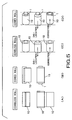
- Figs 4 and 5 are views of assistance in explaining an effect of preventing the deformation of the thermal transfer recording web roll 10.
- a thermal transfer recording web roll provided with a core 1 is formed by winding a thermal transfer recording web around the hard cylindrical core 1 under a specified tension and a specified pressure around a hard, cylindrical core 1, and therefore the position of the thermal transfer recording web roll formed on the core cannot be adjusted relative to the core 1.
- the thermal transfer recording web roll 10 in the first embodiment is easily deformable because the thermal transfer recording web roll 10 in the first embodiment, which is a coreless thermal transfer recording web roll, is formed by winding the thermal transfer recording web 10a under low pressure and low tension, the shape of the thermal transfer recording web roll 10 can easily be corrected, there is no problem in the position of the thermal transfer recording web roll 10 relative to a core, and hence the thermal transfer recording web roll 10 is easy to use and handle.
- Fig. 6 is a view of assistance in explaining the effect of the sticking parts 11b of the thermal transfer recording web 10a.
- the thermal transfer recording web 10 loosens and the diameter of the thermal transfer recording web roll 10 increases at a stage immediately before the thermal transfer recording web 10 is usedup. Consequently, the thermal transfer recording web 10a comes into contact with the inner surfaces of walls of the printer 5 in the vicinity of the thermal transfer recording web roll 10, the thermal transfer recording web 10a is rubbed with the walls and scraps and fragments of the thermal transfer recording web 10a adhere to the inner surfaces of the walls of the printer 5.
- Dyes cannot be printed on thus flawed or scratched parts of the thermal transfer recording web 10a and on parts of the recording layer 32 covered with the scraps and fragments of the thermal transfer recording web 10a scattered in the printer 5, and the printing ribbon cannot normally be separated form those parts of the thermal transfer recording web 10a.
- the thermal transfer recording web 10a needs to be wound in several turns to hold the thermal transfer recording web roll 10 in its shape.
- the thermal transfer recording web roll 10 cannot be held when the thermal transfer recording web 10a is wound in one layer.
- the flanges 5b of the printer 5 are able to hold the thermal transfer recording web roll 10 between the flanges 5b even if the thermal transfer recording web roll 10 has only one layer.
- an optimum method of attaching the sticking parts 11b to the inner surface of the innermost layer must selectively be determined taking into consideration an end detecting method by which the printer detects the end of the thermal transfer recording web 10a of the thermal transfer recording web roll 10.
- Fig. 7 is a view of assistance in explaining the relation between an end detecting method of detecting an end part to be carried out by the printer, and an attaching method of attaching the inner end part of the thermal transfer recording web 10a to the innermost layer of the thermal transfer recording web roll 10.
- the printer 5 When the printer 5 is provided with a sensor that detects light passed through an end indicating hole 2 formed in the thermal transfer recording web 10a or light reflected from an end indicating mark 2a marked on the thermal transfer recording web 10a of the thermal transfer recording web roll 10, a thermal transfer recording web feed mechanism included in the printer 5 stops when the sensor detects the light passed through the end indicating hole 2 or the light reflected from the end indicating mark 2a. Therefore, the sticking parts 11b may be of any shape provided that the sticking parts 11b are attached to the innermost layer (Figs. 7(A) and 7(B)).
- the thermal transfer recording web 10a of the thermal transfer recording web roll 10 is provided with neither any hole corresponding to the end indicating hole 2 nor any mark corresponding to the end indicating mark 2a, and the printer 5 detects a change in the torque acting on the thermal transfer recording web feed mechanism, the shape of the sticking parts 11b must selectively be determined so that the printer 5 is able to detect the change in the torque (Figs. 7(C) and 7(D)).
- the sticking parts 11b may be attached to the innermost layer with adhesivemeans capable of sticking to the innermost layer, such as adhesive double-coated tapes 14a, adhesive tapes or an adhesive (Fig. 7(E)) .
- adhesivemeans capable of sticking to the innermost layer such as adhesive double-coated tapes 14a, adhesive tapes or an adhesive (Fig. 7(E)) .
- the adhesive strength bonding the sticking parts 11b to the innermost layer must withstand the peeling effect of a take-up torque applied to the thermal transfer recording web roll 10 by the printer 5.
- the printer stops upon the separation of the sticking parts 11b from the innermost layer. Therefore, the sticking surfaces of the sticking parts 11b must become tack-free (nonadhesive) after the sticking parts 11b have been separated from the innermost layer.
- the bond strength between the sticking parts 11b and the innermost layer should not be excessively high, and the sticking parts 11b must be separated from the innermost layer when a torque not higher than the take-up torque and not lower than a predetermined level acts on the thermal transfer recording web roll 10. Therefore, it is preferable to use the pseudoadhesive double-coated tapes 14 (Fig. 7(F)).
- the thermal transfer recording web 10a of the thermal transfer recording web roll 10 in this embodiment is provided with the end indicating hole 2 as shown in Fig. 3 and is intended to be used on a printer 5 that detects the end indicating hole.
- the thermal transfer recording web roll 10 can be used on a printer 5 that detects neither an end indicating hole nor an end indicating mark and decides that the thermal transfer recording web 10a is substantially used up when the take-up torque decreases to a naught.
- the pseudoadhesive double-coated tape 14 will be explained.
- the pseudoadhesive double-coated tape 14 has either of the following two forms.
- a molten resin is extruded through a T-die or the like on a nonwoven tape (or a plastic base) to form a resin layer, and the nonwoven tape (or the plastic base) is laminated to a plastic base (or a nonwoven tape), an adhesive layer is formed on the surface of the nonwoven tape (or the plastic base), an adhesive layer is formed on the surface of the plastic base (or the nonwoven tape), and then release tapes are applied to the adhesive layers.
- Suitable resins for forming the resin layer include polypropylene resin , such as Novatec-P available from Mitsubishi Kagaku, polyolefin resins, such as TPX (polymethylpentene) available from Mitsui Kagaku, polyamide resins, ionomers and nylons.
- the thermal transfer recording web roll 10 in the first embodiment is a coreless roll, the thermal transfer recording web can be rolled without using any core and much time and labor at a low cost, and pictures of satisfactory picture quality can be printed by thermal transfer printing on the thermal transfer recording web.
- Fig. 8 shows a thermal transfer recording web roll 10 in a second embodiment according to the present invention
- the thermal transfer recording web roll 10 in the second embodiment is the same in construction as the thermal transfer-recording web roll 10 in the first embodiment, except that the former is provided with a radio frequency identification tag 20 near an inner end part 11 of the thermal transfer recording web 10a.
- the radio frequency identification tag 20 is a noncontact IC tag (RFID) attached to a part near the inner end part 11 of the inner surfaces of the thermal transfer recording web roll 10. Information about the type, size and such of the thermal transfer recording web roll 10 is recorded on the noncontact IC tag.
- RFID noncontact IC tag
- the coreless thermal transfer recording web roll 10 is able to hold necessary information and the printer is able to use the information.
- the tab 11a and the sticking parts 11b are arranged along the width of the thermal transfer recording web 10a in the foregoing embodiments, the tab 11a may be formed in a middle part with respect to the width of the thermal transfer recording web 10a so as to protrude in the winding direction, and a sticking part 11b may be formed in the inner end part as shown in Figs. 9 (A) and 9(B).
- the sticking part 11b and a pseudoadhesive double-coated tape 14 are indicated by broken lines.
- An adhesive layer 37 may be formed on a surface of the base web 30, opposite to the recording layer 31 of the thermal transfer recording web 10a of the thermal transfer recording web roll 10 in the first embodiment, and a release tape 38 may be applied to the adhesive layer 37 to use the thermal transfer recording web 10a as a photograph sealing web.
Landscapes
- Impression-Transfer Materials And Handling Thereof (AREA)
- Thermal Transfer Or Thermal Recording In General (AREA)
Description
- The present invention relates to a thermal transfer recording web roll to be used on a thermal transfer printer.
- There are a variety of thermal transfer methods using thermal transfer sheets made by forming color transfer layers on base sheets. The color transfer layers of the thermal transfer sheets are heated from behind the thermal transfer sheets with a thermal head or the like in patterns for yellow, magenta and cyan images of characters, figures or patterns, respectively, and the patterned yellow, magenta and cyan layers are transferred to the surface of a transfer recording medium. Thermal transfer methods are classified roughly by the type of the color transfer layers into those of the sublimation transfer system and those of the melt transfer system. The thermal transfer method of the sublimation transfer system uses thermal transfer sheets made by forming color transfer layers each of a binder containing a dye that sublimates or shifts when heated on base sheets, heats the thermal transfer sheets from behind to make the dyes contained in the color transfer layers transfer from the thermal transfer sheets to a recording medium. The surface of the recording medium is coated with a recording layer that can easily be dyed.
- The thermal transfer method of the melt transfer system uses thermal transfer sheets made by forming color transfer layers that soften, melt and become transferable when heated on base sheets, heats the thermal transfer sheets from behind to transfer the color transfer layers to the surface of a recording medium. Both the thermal transfer methods of the sublimation transfer system and those of the melt transfer system are capable of forming monochromatic images and multicolor images. In forming a multicolor image, the thermal transfer method uses three or four color thermal transfer sheets for, for example, yellow, magenta and cyan images or, when necessary, yellow, magenta, cyan and black images, and thermally transfers the color images of those colors to a recording medium to form color images.
- The thermal transfer method holds a plurality of thermal transfer recording sheets in a stack and feeds the thermal transfer recording sheets to a printer or uses a thermal transfer recording web roll and feeds the thermal transfer recording web to a printer.
- Recently, the thermal transfer method is used for the thermal transfer recording of a large amount of prints, and thermal transfer recording web rolls are used. The thermal transfer recording web roll, in general, is formed by winding a thermal transfer recording web around a feed core (bobbin). The leading edge of the recording web wound around the feed core is attached adhesively to a take-up core and is taken up on the take-up core after the completion of thermal transfer recording or the recording web is cut in a sheet after the completion of thermal transfer recording and the printed recording sheet is delivered.
- The aforesaid conventional thermal transfer recording web roll has the following problems.
- (1) The conventional thermal transfer recording web roll needs a feed core formed in a high dimensional accuracy to roll the thermal transfer recording web uniformly around the feed core without creasing the thermal transfer recording web. Thus, the feed core is inevitably costly.
A feed core of a reduced cost may be a paper tube formed mainly of paper pulp instead of a plastic material. The paper tube is brought into contact with a driving member of a printer to rotate the thermal transfer recording web roll on the printer. Paper powder is produced due to the abrasion of the paper tube by the driving member in rotating the thermal transfer recording web roll, the paper powder scatters in the printer and, consequently, pinholes are formed in prints formed by thermal transfer printing deteriorating image quality. - (2) The core is mere waste after the thermal transfer recording web held thereon has been used up. Since the cylindrical core is bulky for its weight, the core cannot efficiently be carried for waste disposal. The core is not recycled and thrown away, which is against demand for waste reduction to avoid environmental problems.
- (3) It takes time and requires troublesome work to store cores, to set a core on a take-up machine for taking up a thermal transfer recording web and to wind a thermal transfer recording web around the core.
- (4) An end part of a thermal transfer recording web cannot correctly attached to a desired part of a core in attaching the end part to the core with an adhesive tape, an adhesive double-coated tape or a paste. The thermal transfer recording web meanders while the same is being wound round the core and, consequently, the width of a thermal transfer recording web roll formed on the core is somewhat greater than that of the thermal transfer recording web. Since the thermal transfer recording web is wound under a specified tension and a specified pressure around a hard, cylindrical core, the position of the thermal transfer recording web roll formed on the core cannotbe adjusted relative to the core. Therefore, the core must have a length greater than the width of the thermal transfer sheet taking into consideration the attachment of the end part of the thermal transfer recording web to an incorrect part of the core, and the formation of a thermal transfer recording web roll having a width greater than the width of the thermal transfer recording web. Thus, the thermal transfer recording web roll formed by winding a thermal transfer recording web around a core is inevitably large.
Sometimes, the thermal transfer recording web roll is deformed when shocks act on the thermal transfer recording web roll when the thermal transfer recording web roll is dropped or handled improperly in carrying the thermal transfer recording web roll or loading the thermal transfer recording web roll into a printer. It is difficult to straighten the deformed, hard thermal transfer recording web roll.
The incorrect winding of the thermal transfer recording web around the core and the deformation of the thermal transfer recording web roll while the thermal transfer recording web roll is handled affect adversely to the accuracy of print position on the thermal transfer recording web. - (5) Flaws corresponding to steps including an end part of the thermal transfer recording web attached to the core and an end detection hole formed in the thermal transfer recording web are formed in the thermal transfer recording web roll due to pressure and tension that act on the thermal transfer recording web, and the flaws become apparent in different densities of prints. Fig. 10 is a view of assistance in explaining the formation of flaws in a thermal
transfer recording web 10a. In Fig. 10flaws 3 due to anend indicating hole 2 and an end part of the thermal transfer recording web attached to acore 1. Sometimes, the hardness of the thermal transfer recording web roll is reduced by adjusting winding tension and winding pressure to prevent the foregoing problem due to the adverse effect of the end part of the thermal transfer recording web attached to the core and the end detecting hole on prints, which, however, could not achieve a desired effect. As a further example, US 2002/0075375 A1 relates to a thermal transfer printer including a thermal transfer recording web roll having a bore and being obtained by rolling a thermal transfer web, wherein a segment of the thermal transfer recording web forming the innermost layer of the thermal transfer recording web roll is fixed to a part of a segment of the same, forming the second innermost layer of the thermal transfer web roll, and wherein a holding device is inserted in the bore of the thermal transfer recording web roll for holding the thermal transfer recording web roll. - It is an object of the present invention to provide a thermal transfer recording web roll to be used on a thermal transfer printer, capable of being produced at a low cost without requiring much time and labor and of producing prints having a high print quality by thermal transfer printing.
- According to the present invention, a thermal transfer recording web roll for use on a printer, formed by winding a thermal transfer recording web having a base web, and a recording layer formed on one of the surfaces of the base web; wherein the thermal transfer recording web is wound in a substantially cylindrical shape, a sticking part sticking to an innermost layer of the thermal transfer recording web is formed in an inner end part of the thermal transfer recording web, and the outer surface of the inner end part of the thermal transfer recording web is held by the inner surface of the innermost layer of the thermal transfer recording web through the sticking part.
- The thermal transfer recording web roll according to the present invention for use on a printer, the sticking part may become tack-free after the outer surface of the inner end part of the thermal transfer recording web is separated from the inner surface of the innermost layer of the thermal transfer recording web.
- The thermal transfer recording web roll according to the present invention for use on a printer, the sticking parts may have a pseudoadhesive property that enables the sticking parts to be separated from the innermost layer of the thermal transfer recording web by a peeling force not higher than a peeling force corresponding to a take-up torque exerted by the printer.
- The thermal transfer recording web roll according to the present invention for use on a printer, the sticking part may include pseudoadhesive a double-coated tape.
- The thermal transfer recording web roll according to the present invention for use on a printer, the inner end part of the thermal transfer recording web is provided with a tab for winding.
- The thermal transfer recording web roll according to the present invention for use on a printer, the inner end part of the thermal transfer recording web has the tab formed in a middle part thereof with respect to the width, and a pair of sticking parts respectively on the opposite sides of the tab.
- The thermal transfer recording web roll according to the present invention, the tab and the sticking parts may be demarcated by slits, respectively.
- The thermal transfer recording web roll according to the present invention, the tab may project in a winding direction of the thermal transfer recording web relative to the sticking parts.
- The thermal transfer recording web roll according to the present invention, the tab may have a rectangular projection projecting from a middle part of the inner end of the thermal transfer recording web.
- The thermal transfer recording web roll according to the present invention, the tabmay have a triangular projection projecting from a middle part of the inner end of the thermal transfer recording web.
- The thermal transfer recording web roll according to the present invention, an adhesive layer may be formed on the other surface of the base web, and a release tape is applied to the adhesive layer.
- The thermal transfer recording web roll according to the present invention, a noncontact IC tag may be attached to a part of the thermal transfer recording web near the inner end part of the thermal transfer recording web.
- The thermal transfer recording web roll according to the present invention, adhesive strength of the sticking part between the innermost layer of the thermal transfer recording web and the inner end part of the thermal transfer recording web is higher than a peeling force corresponding to a take-up torque exerted by the printer.
-
- Fig. 1 is a perspective view of a thermal transfer recording web roll in a first embodiment according to the present invention in an unused state;
- Fig. 2 is a plan view of an inner end part of a thermal transfer recording web unwound from the thermal transfer recording web roll shown in Fig. 1;
- Fig. 3 is a perspective view of an innermost layer of a thermal transfer recording web;
- Fig. 4 is a view of assistance in explaining an effect of preventing the deformation of a thermal transfer recording web roll;
- Fig. 5 is a view of assistance in explaining an effect of preventing the deformation of a thermal transfer recording web roll;
- Fig. 6 is a view of assistance in explaining the effect of a sticking part;
- Fig. 7 is a view of assistance in explaining the relation between an end detecting method of detecting an end part to be carried out by a printer, and an inner end part attaching method;
- Fig. 8 is an end view of a thermal transfer recording web roll in a second embodiment according to the present invention;
- Fig. 9 is a view of thermal transfer recording webs in modifications; and
- Fig. 10 is a view showing flaws formed in an inner end part of a thermal transfer recording web forming a conventional thermal transfer recording web roll.
- Preferred embodiments of the present invention will be described with reference to the accompanying drawings.
- Fig. 1(A) shows an unused thermal transfer recording web roll in a first embodiment according to the present invention, and Fig. 1(B) is a sectional view of a thermal
transfer recording web 10a. - A thermal transfer
recording web roll 10 in the first embodiment is formed by rolling the thermaltransfer recording web 10a, and has aninner end part 11, anouter end part 12 and afastening tape 13. - As shown in Fig. 1(B), the thermal
transfer recording web 10a has abase web 30, anintermediate layer 31 formed on one of the surfaces of thebase web 30, and arecording layer 32 formed on a surface of theintermediate layer 31. - Preferably, the
base web 30 has a mechanical strength sufficient for preventing troubles in handling because thebase web 30 holds therecording layer 32 thereon and is heated in transferring an image thereto by thermal transfer. There are not any particular restrictions on the material forming thebase web 30. Thebase web 30 may be formed of cellulose paper, such as condenser paper, glassine paper, parchment paper, paper having a high degree of sizing, synthetic paper (polyolefin paper and polystyrene paper), wood-free paper, art paper, cast coated paper, wall paper, lining paper, paper impregnated with a synthetic resin of an emulsion, paper impregnated with synthetic rubber latex, cardboard, may be formed of a film of one of polyester resins, polyacrylate resins, polycarbonate resins, polyurethane resins, polyimide resins, polyether imide resins, cellulose derivatives, polyethylene resins, ethylene-vinyl acetate copolymers, polypropylene resins, polystyrene resins, acrylic resins, polyvinyl chloride resins, polyvinylidene chloride resins, polyvinyl alcohol resins, polyvinyl butyral resins, nylons, polyether ether ketone resins, polysulfone resins, polyether sulfone resins, tetrafluoroethylene perfluoroalkylvinyl ether resins, polyvinyl fluoride resins, tetrafluoroethylene ethylene resins, tetrafluoroethylene hexafluoropropylene resins, polychlorotrifluoroethylene resins, and polyvinylidene fluoride resins. Thebaseweb30maybeawhite, opaque filmof a material prepared by mixing one of the foregoing synthetic resins and a white pigment or filler or may be a foam web. - The
base web 30 may be a laminate formed by laminating webs of the foregoing materials. A typical laminate may be a synthetic paper sheet formed by laminating a cellulose paper sheet and a synthetic paper sheet, or a synthetic paper sheet formed by laminating a cellulose paper sheet and a plastic film. The thickness of thebase web 30 is optional. Usually, the thickness of thebase web 30 is in the range of about 10 to about 300 µm. If the adhesion between thebase web 30 and theintermediate layer 31 is insufficient, it is preferable to coat the surface of thebase web 30 with a primer to finish the surface of thebase web 30 by a corona discharge treatment. - The
intermediate layer 31 is formed on thebase web 30 mainly for coloring the recording surface and opacification to conceal thebase web 30. A material forming theintermediate layer 31 contains two or more kinds of dyes, a white pigment, necessary additives and a resin as a binder. Resins suitable for forming theintermediate layer 31 are, for example, thermoplastic resins, such as polyurethane resins, acrylic resins, polyester resins and polycarbonate resins, and thermosetting resins, such as resins obtained through the partial crosslinking of the aforesaid resins, crosslinked polyurethane resins, epoxy resins, melamine resins and urea resins. - The white pigment may be an inorganic pigment, such as titanium oxide, zinc oxide, barium sulfate or alumina white, an extender pigment, such as kaolin clay, silica, magnesium carbonate or calcium carbonate, or a mixture of some of those pigments.
- The
intermediate layer 31 is formed by an intermediate layer forming method including the steps of preparing a coating liquid by dissolving or dispersing the aforesaid resin, at least two kinds of dyes, a white pigment and, when necessary, additives in a suitable organic solvent, such as ethyl acetate, methyl ethyl ketone, toluene, xylene or cyclohexanone, coating at least one of the surfaces of thebase web 30 with a coating layer of the coating liquid by a coating means, such as a gravure coating process, a screen printing process or a reverse-roll coating process using a gravure plate, drying the coating layer and, when necessary, subjecting the coating layer to a crosslinking process. Theintermediate layer 31 thus formed has a solid basis weight in the range of about 0.5 to 10g/m2, more preferably, in the range of 1 to 6 g/m2. An excessively thin intermediate layer is unable to exhibit a desired effect. The effect of an intermediate layer does notenhancebeyonda certain level even if the thickness thereof is increased excessively, and an excessively thick intermediate layer reduces print sensitivity. - The
recording layer 32 formed on theintermediate layer 31 formed on thebase web 30 receives when heated a dye transferred from a thermal transfer sheet and records an image formed thereon. Materials suitable for forming therecording layer 32 are polyolefin resins, such as polypropylene resins, halogenated polymers, such as polyvinyl chloride resins and polyvinylidene chloride resins, vinyl resins, such as polyvinyl acetate resins, ethylene-vinyl acetate copolymers, vinyl chloride-acetate copolymers and polyacrylate resins, acetal resins, such as polyvinyl formal resins, polyvinylbutyral resins and polyvinyl acetal resins, saturated and unsaturated polyester resins, polycarbonate resins, cellulose resins, such as cellulose acetate resins, styrene resins, such as polystyrene resins, acryl-styrene copolymers and acrylonitril-styrene copolymers, urea resins, melamine resins, and polyamide resins, such as benzoguanamine resins. Therecording layer 32 may be formed of a compatible blend of some of the foregoing resins. - When the binder contained in the
intermediate layer 31 is a resin having active hydrogen in hydroxyl groups or carboxyl groups, addition of a curing agent that react with active hydrogen in therecording layer 32 enhances the adhesion between theintermediate layer 31 and therecording layer 32. Preferable curing agents for such a purpose are isocyanate compounds, amino compounds, and organometallic compounds. Catalysts respectively suitable for use in combination with those curing agents may be used to increase the reaction rates of the curing agent. It is preferable that the least necessary amount of curing agent is added to the material forming therecording layer 32 in order to adhere to theintermediate layer 31. - In some cases, the resin contained in the
recording layer 32 fuses with a dye binder holding a dye during the thermal transfer image recording. Therefore, it is preferable that therecording layer 32 contains a lubricant, such as aphosphate, a surface-active agent, a fluorine compound, a fluorine resin, a silicon compound, a silicone oil or a silicone resin, to provide therecording layer 32 with a satisfactory release characteristic. It is particularly preferable to add a modified silicone oil to and to cure therecording layer 32. Although the lubricant content is dependent on the type of the lubricant, it is preferable that the lubricant content is the leastpossible value that is sufficient for the lubricant to satisfactorily exercise its effect in the range of 1 to 20 parts by weight on the solidbases. When a modified silicone oil having reactive groups capable of reacting with the curing agent is added to therecording layer 32, it is preferable that the ratio of the equivalent weight of the reactive groups of the modified silicone oil to that of the reactive groups of the curing agent is in the range of 1 : 1 to 1 : 10. A releasing layer, i.e., a layer of the aforesaid lubricant or a layer of a mixture of the binder and the aforesaid lubricant, may be formed on the recording layer instead of adding the lubricant to the recording layer. - The
recording layer 32 is formed by applying a coating liquid prepared by dissolving or dispersing a mixture of a resin and necessary additives in an organic solvent to theintermediate layer 31 by a coating process, such as a gravure printing process, a screen printing process or a reverse-roll coating process using a gravure plate, in a coating layer and drying the coating layer. Although the recording layer may have any thickness, the thickness of the recording layer, in general, is in the range of 1 to 50 µm. - A
slip layer 33 may be formed on the back surface of thebase web 30 of the thermaltransfer recording web 10a to improve the facility of mechanical carrying of the thermaltransfer recording web 10a and to prevent the curling of the thermaltransfer recording web 10a. It is preferable to add a proper amount of an organic or inorganic filler to the binder or to use a resin having a high lubricity, such as a polyolefin resin or a cellulose resin, as the binder. Theslip layer 33 may be formed of a mixture prepared by adding as additives, an organic filler, such as an acrylic filler, a nylon filler, a Teflon® filler or a polyethylene wax, and an inorganic filler, such as silicon dioxide or a metal oxide, to a resin, such as an acrylic resin, a cellulose resin, a polycarbonate resin, a polyvinyl acetal resin, a polyvinyl alcohol resin, a polyamide resin, a polystyrene resin, a polyester resin or a halogenated polymer. An acrylic resin is preferable and an acrylpolyol is most preferable. It is preferable to use a resin obtained by curing an acrylpolyol with a curing agent. - The
slip layer 33 is formed by applying a coating liquid prepared by thoroughly kneading a mixture prepared by mixing the aforesaid resin, a filler, a solvent and a diluent to the back surface of thebase web 30 by a coating process, such as a gravure printing process, a screen printing process or a reverse-roll coating process using a gravure plate, in a coating layer and drying the coating layer. Although theslip layer 33 may have any thickness, the thickness of theslip layer 33, in general, is in the range of 1 to 10 µm - An
adhesive layer 34 of an adhesive resin, such as an acrylate resin, a polyurethane resin or a polyester resin, may be formed on the surface and/or the back surface of thebase web 30. Theadhesive layer 34 is formed by applying a coating liquid containing the aforesaid resin to the surface and/or the back surface of thebase web 30 by a coating process, such as a gravure printing process, a screen printing process or a reverse-roll coating process using a gravure plate, in a coating layer and drying the coating layer. The surface and/or the back surface of thebase web 30 may be processed by a corona discharge process instead of coating the surface and/or the back surface of thebase web 30 with the coating layer to enhance adhesion between thebase web 30 and the layer formed on the former. - An
antistatic layer 35 may be formed on at least one of the outermost surfaces of the thermaltransfer recording web 10a. Theantistatic layer 35 is formed by spreading a coating liquid prepared by dissolving or dispersing a fatty ester, a sulfate, a phosphate, an amide, a quaternary ammonium salt, betaine, an amino acid or an ethylene oxide addition product in a solvent. Theantistatic layer 35 may be formed by spreading a conductive resin produced by introducing a group having an antistatic effect, such as a quaternary ammoniumsalt, aphosphate, anethosulfate, a vinylpyrrolidone or sulfonic acid, into an acrylic resin, a vinyl resin or a cellulose resin or an antistatic resin produced through the copolymerization of such an antistatic group and such a resin. Preferably, the basis weight of theantistatic layer 35 is in the range of 0.001 to 0.1 g/m2. Theantistatic layer 35 may be formed by a spraying process or a transfer process instead of a coating process. The thermaltransfer recording web 10a provided with theantistatic layer 35 has an excellent antistatic property and is capable of preventing double-sheet feeding. - The
inner end part 11 of the rolled thermaltransfer recording web 10a has atab 11a and stickingparts 11b. - Fig. 2 shows the
inner end part 11 of the thermaltransfer recording web 10a unwound from the thermal transferrecording web roll 10. - A winding machine used in a manufacturing process catches the thermal
transfer recording web 10a by thetab 11a in winding the thermaltransfer recording web 10a in the thermal transferrecording web roll 10. Theinner end part 11 is cut into three parts byslits 11c. Thetab 11a is the middle one of those three parts. - The two parts on the opposite sides, with respect to the width, of the
tab 11a are the stickingparts 11b. Pseudoadhesive double-coatedtapes 14 are attached to the back surfaces (outer surfaces) of the stickingparts 11b. The pseudoadhesive double-coatedtapes 14 stick to the innermost layer, i. e. , the first layer, of the thermal transferrecording web roll 10 formed by rolling the thermaltransfer recording web 10a. The stickingparts 11b provided with the pseudoadhesive double-coatedtapes 14 loose their sticking property after the stickingparts 11b have been separated from the inner surface of the innermost layer of the thermaltransfer recording web 10a. - The
outer end part 12 is fastened temporarily to the thermaltransfer recording web 10a with afastening tape 13 to prevent the thermal transferrecording web roll 10 from coming loose. - Fig. 3 shows the innermost layer formed by rolling the thermal
transfer recording web 10a. - The sticking
parts 11b of theinner end part 11 of the thermaltransfer recording web 10a stick. Thus, theinner end part 11 is held in place on the innermost layer as shown in Fig. 3 without using any core. - Since the winding machine grips the
tab 11a in winding the thermaltransfer recording web 10a, thetab 11a is curved permanently radially inward as shown in Figs. 1 and 3. If theinner end part 11 is entirely a sticking part, theinner end part 11 extends radially inward and interferes with a mountingshaft 5a included in aprinter 5 in loading the thermal transferrecording web roll 10 into theprinter 5, which makes a loading operation difficult and cause faulty loading. - In this embodiment, the
tab 11a is at the middle, with respect to the width, of theinner end part 11 of the thermaltransfer recording web 10a, and the stickingparts 11b extend in a circular shape conforming to the innermost layer. Therefore, thetab 11a will not obstruct the insertion of the mountingshaft 5a of theprinter 5 into the thermal transferrecording web roll 10. Thus, the thermal transferrecording web roll 10 can easily and correctly loaded into theprinter 5. - Figs 4 and 5 are views of assistance in explaining an effect of preventing the deformation of the thermal transfer
recording web roll 10. - A thermal transfer recording web roll provided with a
core 1 is formed by winding a thermal transfer recording web around the hardcylindrical core 1 under a specified tension and a specified pressure around a hard,cylindrical core 1, and therefore the position of the thermal transfer recording web roll formed on the core cannot be adjusted relative to thecore 1. Although the thermal transferrecording web roll 10 in the first embodiment is easily deformable because the thermal transferrecording web roll 10 in the first embodiment, which is a coreless thermal transfer recording web roll, is formed by winding the thermaltransfer recording web 10a under low pressure and low tension, the shape of the thermal transferrecording web roll 10 can easily be corrected, there is no problem in the position of the thermal transferrecording web roll 10 relative to a core, and hence the thermal transferrecording web roll 10 is easy to use and handle. - Fig. 6 is a view of assistance in explaining the effect of the sticking
parts 11b of the thermaltransfer recording web 10a. - If the
inner endpart 11 of the thermal transferrecording web roll 10 is not provided any parts corresponding to the stickingparts 11b and the thermal transferrecording web roll 10 is used on theprinter 5, the thermaltransfer recording web 10 loosens and the diameter of the thermal transferrecording web roll 10 increases at a stage immediately before the thermaltransfer recording web 10 is usedup. Consequently, the thermaltransfer recording web 10a comes into contact with the inner surfaces of walls of theprinter 5 in the vicinity of the thermal transferrecording web roll 10, the thermaltransfer recording web 10a is rubbed with the walls and scraps and fragments of the thermaltransfer recording web 10a adhere to the inner surfaces of the walls of theprinter 5. Dyes cannot be printed on thus flawed or scratched parts of the thermaltransfer recording web 10a and on parts of therecording layer 32 covered with the scraps and fragments of the thermaltransfer recording web 10a scattered in theprinter 5, and the printing ribbon cannot normally be separated form those parts of the thermaltransfer recording web 10a. - If the
inner end part 11 of the thermal transferrecording web roll 10 is not provided any parts corresponding to the stickingparts 11b, the thermaltransfer recording web 10a needs to be wound in several turns to hold the thermal transferrecording web roll 10 in its shape. Whenflanges 5b included in theprinter 5 are pressed against the opposite ends of the thermal transferrecording web roll 10 to hold the thermal transferrecording web roll 10 in place, the thermal transferrecording web roll 10 cannot be held when the thermaltransfer recording web 10a is wound in one layer. - Since the
inner end part 11 of the thermal transferrecording web roll 10 in this embodiment is provided with the stickingparts 11b, theflanges 5b of theprinter 5 are able to hold the thermal transferrecording web roll 10 between theflanges 5b even if the thermal transferrecording web roll 10 has only one layer. - Although the pseudoadhesive double-coated
tapes 14 are attached to the stickingparts 11b in this embodiment, an optimum method of attaching the stickingparts 11b to the inner surface of the innermost layer must selectively be determined taking into consideration an end detecting method by which the printer detects the end of the thermaltransfer recording web 10a of the thermal transferrecording web roll 10. - Fig. 7 is a view of assistance in explaining the relation between an end detecting method of detecting an end part to be carried out by the printer, and an attaching method of attaching the inner end part of the thermal
transfer recording web 10a to the innermost layer of the thermal transferrecording web roll 10. - When the
printer 5 is provided with a sensor that detects light passed through anend indicating hole 2 formed in the thermaltransfer recording web 10a or light reflected from anend indicating mark 2a marked on the thermaltransfer recording web 10a of the thermal transferrecording web roll 10, a thermal transfer recording web feed mechanism included in theprinter 5 stops when the sensor detects the light passed through theend indicating hole 2 or the light reflected from theend indicating mark 2a. Therefore, the stickingparts 11b may be of any shape provided that the stickingparts 11b are attached to the innermost layer (Figs. 7(A) and 7(B)). - When the thermal
transfer recording web 10a of the thermal transferrecording web roll 10 is provided with neither any hole corresponding to theend indicating hole 2 nor any mark corresponding to theend indicating mark 2a, and theprinter 5 detects a change in the torque acting on the thermal transfer recording web feed mechanism, the shape of the stickingparts 11b must selectively be determined so that theprinter 5 is able to detect the change in the torque (Figs. 7(C) and 7(D)). - When the approach of the end is indicated by the duration of a maximum take-up torque for a predetermined time, the sticking
parts 11b may be attached to the innermost layer with adhesivemeans capable of sticking to the innermost layer, such as adhesive double-coatedtapes 14a, adhesive tapes or an adhesive (Fig. 7(E)) . The adhesive strength bonding the stickingparts 11b to the innermost layer must withstand the peeling effect of a take-up torque applied to the thermal transferrecording web roll 10 by theprinter 5. - When the approach of the end is indicated by the reduction of the take-up torque to naught, the printer stops upon the separation of the sticking
parts 11b from the innermost layer. Therefore, the sticking surfaces of the stickingparts 11b must become tack-free (nonadhesive) after the stickingparts 11b have been separated from the innermost layer. The bond strength between the stickingparts 11b and the innermost layer should not be excessively high, and the stickingparts 11b must be separated from the innermost layer when a torque not higher than the take-up torque and not lower than a predetermined level acts on the thermal transferrecording web roll 10. Therefore, it is preferable to use the pseudoadhesive double-coated tapes 14 (Fig. 7(F)). - The thermal
transfer recording web 10a of the thermal transferrecording web roll 10 in this embodiment is provided with theend indicating hole 2 as shown in Fig. 3 and is intended to be used on aprinter 5 that detects the end indicating hole. However, since the stickingparts 11b are attached to the innermost layer with the pseudoadhesive double-coatedtapes 14, the thermal transferrecording web roll 10 can be used on aprinter 5 that detects neither an end indicating hole nor an end indicating mark and decides that the thermaltransfer recording web 10a is substantially used up when the take-up torque decreases to a naught. - The pseudoadhesive double-coated
tape 14 will be explained. - The pseudoadhesive double-coated
tape 14 has either of the following two forms. - (1) Release tape/Adhesive layer/Nonwoven or paper tape/Resin layer/Plastic base/Adhesive layer/Release tape
- (2) Release tape/Adhesive layer/Plastic base/Resin layer/Plastic base/Adhesive layer/Release tape
- In forming the pseudoadhesive double-coated tape of the form (1), a molten resin is extruded through a T-die or the like on a nonwoven tape (or a plastic base) to form a resin layer, and the nonwoven tape (or the plastic base) is laminated to a plastic base (or a nonwoven tape), an adhesive layer is formed on the surface of the nonwoven tape (or the plastic base), an adhesive layer is formed on the surface of the plastic base (or the nonwoven tape), and then release tapes are applied to the adhesive layers.
- Suitable resins for forming the resin layer include polypropylene resin , such as Novatec-P available from Mitsubishi Kagaku, polyolefin resins, such as TPX (polymethylpentene) available from Mitsui Kagaku, polyamide resins, ionomers and nylons.
- Since the thermal transfer
recording web roll 10 in the first embodiment is a coreless roll, the thermal transfer recording web can be rolled without using any core and much time and labor at a low cost, and pictures of satisfactory picture quality can be printed by thermal transfer printing on the thermal transfer recording web. - Fig. 8 shows a thermal transfer
recording web roll 10 in a second embodiment according to the present invention, - The thermal transfer
recording web roll 10 in the second embodiment is the same in construction as the thermal transfer-recording web roll 10 in the first embodiment, except that the former is provided with a radiofrequency identification tag 20 near aninner end part 11 of the thermaltransfer recording web 10a. - The radio
frequency identification tag 20 is a noncontact IC tag (RFID) attached to a part near theinner end part 11 of the inner surfaces of the thermal transferrecording web roll 10. Information about the type, size and such of the thermal transferrecording web roll 10 is recorded on the noncontact IC tag. When the thermal transferrecording web roll 10 is loaded into aprinter 5, a read-write head R/W reads the information held by the noncontact IC tag. - Since the radio
frequency identification tag 20 is attached to the thermal transferrecording web roll 10, the coreless thermal transferrecording web roll 10 is able to hold necessary information and the printer is able to use the information. - The present invention is not limited in its practical application to the foregoing embodiments, various modifications of the foregoing embodiments may be made and various changes are possible in the foregoing embodiments without departing from the scope of the present invention.
- For example, although the
tab 11a and the stickingparts 11b are arranged along the width of the thermaltransfer recording web 10a in the foregoing embodiments, thetab 11a may be formed in a middle part with respect to the width of the thermaltransfer recording web 10a so as to protrude in the winding direction, and a stickingpart 11b may be formed in the inner end part as shown in Figs. 9 (A) and 9(B). In Figs. 9 (A) and 9(B), the stickingpart 11b and a pseudoadhesive double-coatedtape 14 are indicated by broken lines. - An
adhesive layer 37 may be formed on a surface of thebase web 30, opposite to therecording layer 31 of the thermaltransfer recording web 10a of the thermal transferrecording web roll 10 in the first embodiment, and arelease tape 38 may be applied to theadhesive layer 37 to use the thermaltransfer recording web 10a as a photograph sealing web. - As apparent form the foregoing description, the present invention has the following effects.
- (1) The thermal transfer
recording web roll 10 can be produced at a low cost because the thermal transferrecording web roll 10 is formed by rolling the thermaltransfer recording web 10a in a substantially cylindrical shape without using any core.
Since the thermal transferrecording web roll 10 is not provided with any core, the thermal transferrecording web roll 10 does not produce unnecessary waste.
The deformation of the thermal transferrecording web roll 10 can easily be corrected and handling of the thermal transferrecording web roll 10 is facilitated.
Any flaws corresponding to steps including an end detection hole formed in the thermal transfer recording web are not formed in the thermal transfer recording web and pictures can be formed in satisfactory picture quality on the thermal transfer recording web. - (2) Since the thermal
transfer recording web 10a is provided with the stickingparts 11b at parts of theinner end part 11 that is in contact with the inner surface of the innermost layer of the thermaltransfer recording web 10a, the thermal transferrecording web roll 10 will not loosen immediately before the thermaltransfer recording web 10a of the thermal transferrecording web roll 10 is used up and thereby troubles that may result from the loosening of the thermal transferrecording web roll 10 can be avoided. - (3) Since the sticking surfaces of the sticking
parts 11b become tack-free after the stickingparts 11b have been separated from the innermost layer, the thermal transferrecording web roll 10 can be used on a printer that detects the end of the thermaltransfer recording web 10a by any detecting method. - (4) The pseudoadhesive sticking parts become tack-free surely and simply after the same have been separated from the innermost layer.
- (5) since the
tab 11a is at the middle of theinner end part 11 of the thermaltransfer recording web 10a, thetab 11a will not obstruct the loading operation for loading the thermaltransfer web roll 10 into theprinter 5 and the thermal transferrecording web roll 10 can easily and correctly loaded into theprinter 5. - (6) Since the
inner end part 11 of the thermaltransfer recording web 10a is provided with theslits 11c demarcating thetab 11a and the adjacent stickingparts 11b, any scraps and fragments are not produced in manufacturing the thermal transferrecording web roll 10. - (7) When the
tab 11a projects in the winding direction, the thermaltransfer recording web 10a can easily be attached to the winding machine. - (8) When the
adhesive layer 37 is formed on the surface, opposite the surface on which therecording layer 32 is formed, of thebase web 30, and therelease tape 38 is attached to theadhesive layer 37, a coreless thermal transfer recording web roll for use on a photograph sealing printing machine can be formed, and even an unskilled operator is able to handle the coreless thermal transfer recording web roll easily. - (9) When the thermal transfer
recording web roll 10 is provided with thenoncontact IC tag 20 in a part of the thermaltransfer recording web 10a near theinner end part 11, the coreless thermal transferrecording web roll 10 is able to hold various pieces of information.
Claims (11)
- A thermal transfer recording web roll for use on a printer, formed by winding a thermal transfer recording web having a base web (30), and a recording layer (32) formed on one of the surfaces of the base web; wherein
the thermal transfer recording web is wound in a substantially cylindrical shape,
a sticking part (11b) sticking to an innermost layer of the thermal transfer recording web is formed in an inner end part (11) of the thermal transfer recording web,
the outer surface of the inner end part (11) of the thermal transfer recording web is held by the inner surface of the innermost layer of the thermal transfer recording web through the sticking part (11b), and
the inner end part (11) of the thermal transfer recording web is provided with a tab (11a) for winding, characterized in that
the inner end part (11) of the thermal transfer recording web has the tab (11a) formed in a middle part thereof with respect to the width, and a pair of sticking parts (11b) respectively on the opposite sides of the tab (11a). - The thermal transfer recording web roll for a printer according to claim 1, wherein
the sticking part (11b) becomes tack-free after the outer surface of the inner end part (11) of the thermal transfer recording web is separated from the inner surface of the innermost layer of the thermal transfer recording web. - The thermal transfer recording web roll for a printer according to claim 1 or 2, wherein
the sticking part (11b) is formed pseudoadhesive and adapted to be separated from the inner most layer of the thermal transfer recording web by a peeling force not higher than a peeling force corresponding to a take-up torque exerted by the printer. - The thermal transfer recording web roll for use on a printer according to claim 3, wherein
the sticking part (11b) includes a pseudoadhesive double-coated tape. - The thermal transfer recording web roll for use on a printer according to claim 1, wherein
the tab (11a) and the sticking parts (11b), are demarcated by slits, respectively. - The thermal transfer recording web roll for use on a printer according to anyone of claims 1-5, wherein
the tab (11a) projects in a winding direction of the thermal transfer recording web relative to the sticking part (11b). - The thermal transfer recording web roll for use on a printer according to anyone of claims 1-6, wherein
the tab (11a) has a rectangular projection projecting from a middle part of the inner end of the thermal transfer recording web. - The thermal transfer recording web roll for use on a printer according to anyone of claims 1-7, wherein
the tab (11a) has a triangular projection projecting from a middle part of the inner end of the thermal transfer recording web. - The thermal transfer recording web roll for use on a printer according to anyone of the preceding claims, wherein
an adhesive layer is formed on the other surface of the base web, and a release tape is applied to the adhesive layer. - The thermal transfer recording web roll for use on a printer according to anyone of the preceding claims, wherein
a noncontact IC tag (20) is attached to a part of the thermal transfer recording web near the inner end part (11) of the thermal transfer recording web. - The thermal transfer recording web roll for use on a printer according to anyone of the preceding claims, wherein
adhesive strength of the sticking part (11b) between the innermost layer of the thermal transfer recording web and the inner end part (11) of the thermal transfer recording web is higher than a peeling force corresponding to a take-up torque exerted by the printer.
Applications Claiming Priority (2)
| Application Number | Priority Date | Filing Date | Title |
|---|---|---|---|
| JP2002181961A JP4090798B2 (en) | 2002-06-21 | 2002-06-21 | Thermal transfer image receiving sheet roll |
| JP2002181961 | 2002-06-21 |
Publications (2)
| Publication Number | Publication Date |
|---|---|
| EP1375172A1 EP1375172A1 (en) | 2004-01-02 |
| EP1375172B1 true EP1375172B1 (en) | 2006-02-08 |
Family
ID=29717546
Family Applications (1)
| Application Number | Title | Priority Date | Filing Date |
|---|---|---|---|
| EP03013450A Expired - Lifetime EP1375172B1 (en) | 2002-06-21 | 2003-06-23 | Thermal transfer recording web roll |
Country Status (5)
| Country | Link |
|---|---|
| US (2) | US6894711B2 (en) |
| EP (1) | EP1375172B1 (en) |
| JP (1) | JP4090798B2 (en) |
| KR (1) | KR100560707B1 (en) |
| DE (1) | DE60303467T2 (en) |
Families Citing this family (15)
| Publication number | Priority date | Publication date | Assignee | Title |
|---|---|---|---|---|
| US6724895B1 (en) | 1998-06-18 | 2004-04-20 | Supersensor (Proprietary) Limited | Electronic identification system and method with source authenticity verification |
| US7137000B2 (en) * | 2001-08-24 | 2006-11-14 | Zih Corp. | Method and apparatus for article authentication |
| US7061516B2 (en) * | 2002-10-21 | 2006-06-13 | Fuji Photo Film Co., Ltd. | Thermal printer, thermal printing method, and thermosensitive recording material |
| US7726599B2 (en) * | 2003-12-31 | 2010-06-01 | Kimberly-Clark Worldwide, Inc. | Apparatus and method for dispensing sheet material |
| ATE371540T1 (en) * | 2004-01-27 | 2007-09-15 | Rossini S P A | PRINTING ELEMENT WITH IDENTIFICATION MEANS AND METHOD FOR EMBEDDING IDENTIFICATION MEANS IN A PRINTING ELEMENT |
| WO2005106598A1 (en) * | 2004-04-28 | 2005-11-10 | Canon Kabushiki Kaisha | Toner |
| US7121457B2 (en) | 2004-04-30 | 2006-10-17 | Kimberly-Clark Worldwide, Inc. | Automatically adjusting parameters of a lifting device by identifying objects to be lifted |
| US9296214B2 (en) | 2004-07-02 | 2016-03-29 | Zih Corp. | Thermal print head usage monitor and method for using the monitor |
| US8917159B2 (en) * | 2005-08-19 | 2014-12-23 | CLARKE William McALLISTER | Fully secure item-level tagging |
| US8721203B2 (en) | 2005-10-06 | 2014-05-13 | Zih Corp. | Memory system and method for consumables of a printer |
| JP2008273641A (en) * | 2007-04-25 | 2008-11-13 | Fujifilm Corp | Thermal transfer image-receiving sheet paper tube, roll-form processed product of thermal transfer image-receiving sheet, and image forming method |
| MX2010005450A (en) * | 2007-12-21 | 2010-06-07 | Georgia Pacific Consumer Prod | Product, dispenser and method of dispensing product. |
| US8833691B1 (en) | 2007-12-21 | 2014-09-16 | Georgia-Pacific Consumer Products Lp | Product, dispenser and method of dispensing product |
| KR101415185B1 (en) * | 2012-12-18 | 2014-07-08 | 세연테크놀로지 주식회사 | RF Tag reader identifying a RFID tag on a sheet winded in a shaft |
| KR200482358Y1 (en) * | 2015-07-28 | 2017-01-13 | 이주희 | Roll sheet for hairdressing |
Family Cites Families (12)
| Publication number | Priority date | Publication date | Assignee | Title |
|---|---|---|---|---|
| US112320A (en) * | 1871-03-07 | Improvement in door-securers | ||
| US4297403A (en) * | 1980-02-06 | 1981-10-27 | Monarch Marking Systems, Inc. | Coreless pressure sensitive label supply roll |
| US5152625A (en) * | 1988-04-13 | 1992-10-06 | Canon Kabushiki Kaisha | Dual use of ribbon sensor in a printing device |
| US5106123A (en) * | 1989-04-24 | 1992-04-21 | Monarch Marking Systems, Inc. | Roll of record members |
| US5086987A (en) * | 1989-04-24 | 1992-02-11 | Monarch Marking Systems, Inc. | Method of making rolls of record members |
| JP2728738B2 (en) * | 1989-06-27 | 1998-03-18 | 王子製紙株式会社 | Thermal recording medium |
| US5318943A (en) * | 1991-05-27 | 1994-06-07 | Dai Nippon Printing Co., Ltd. | Thermal transfer image receiving sheet |
| JP2001139192A (en) | 1999-11-15 | 2001-05-22 | Sato Corp | Roll paper for printing |
| US6478229B1 (en) * | 2000-03-14 | 2002-11-12 | Harvey Epstein | Packaging tape with radio frequency identification technology |
| JP3366893B2 (en) | 2000-03-17 | 2003-01-14 | 大王製紙株式会社 | Coreless sheet roll, method and apparatus for manufacturing the same |
| KR100416933B1 (en) | 2000-12-20 | 2004-02-05 | 다이니폰 인사츠 가부시키가이샤 | Thermal transfer printer, thermal transfer recording method and thermal transfer recording web roll |
| JP2003043638A (en) * | 2001-08-02 | 2003-02-13 | Fuji Photo Film Co Ltd | Production control method for photographic film |
-
2002
- 2002-06-21 JP JP2002181961A patent/JP4090798B2/en not_active Expired - Fee Related
-
2003
- 2003-06-19 US US10/464,861 patent/US6894711B2/en not_active Ceased
- 2003-06-20 KR KR1020030040215A patent/KR100560707B1/en not_active Expired - Fee Related
- 2003-06-23 EP EP03013450A patent/EP1375172B1/en not_active Expired - Lifetime
- 2003-06-23 DE DE60303467T patent/DE60303467T2/en not_active Expired - Lifetime
-
2007
- 2007-03-27 US US11/728,981 patent/USRE42427E1/en not_active Expired - Lifetime
Also Published As
| Publication number | Publication date |
|---|---|
| JP2004025500A (en) | 2004-01-29 |
| KR20040004059A (en) | 2004-01-13 |
| KR100560707B1 (en) | 2006-03-16 |
| US6894711B2 (en) | 2005-05-17 |
| JP4090798B2 (en) | 2008-05-28 |
| US20040004657A1 (en) | 2004-01-08 |
| DE60303467T2 (en) | 2006-10-19 |
| EP1375172A1 (en) | 2004-01-02 |
| DE60303467D1 (en) | 2006-04-20 |
| USRE42427E1 (en) | 2011-06-07 |
Similar Documents
| Publication | Publication Date | Title |
|---|---|---|
| USRE42427E1 (en) | Thermal transfer recording web roll | |
| US5646090A (en) | Thermal transfer image-receiving sheet | |
| US6395375B1 (en) | Composite thermal transfer sheet | |
| US5569515A (en) | Printable linerless label and method for making same | |
| US5162141A (en) | Polymeric sheet having an incompatible ink permanently bonded thereto | |
| EP1219453B1 (en) | Thermal transfer printer, thermal transfer recording method and thermal transfer recording web roll | |
| US5569638A (en) | Roll-type heat transfer image-receiving sheet | |
| US6656881B2 (en) | Thermal Transfer image-receiving sheet | |
| JP4467811B2 (en) | Thermal transfer printer, thermal transfer recording method, and thermal transfer image receiving sheet roll | |
| JP2810178B2 (en) | Rolled composite thermal transfer sheet | |
| JP3776725B2 (en) | Thermal transfer printer, thermal transfer recording method, and thermal transfer image receiving sheet roll | |
| JPH09278292A (en) | Thermal transfer sheet roll and thermal transfer image receiving sheet roll | |
| EP1388424B1 (en) | Receiving paper for thermal transfer recording and manufacturing method thereof | |
| JP3367250B2 (en) | Thermal transfer receiving sheet | |
| JPH0494979A (en) | Leaf type composite heat transfer sheet | |
| JP2002187299A (en) | Thermal transfer printer, thermal transfer recording method, and thermal transfer image receiving sheet roll | |
| JPH11105919A (en) | Image receiving sheet package | |
| JPH09174997A (en) | Ink jet recording sheet and manufacturing method thereof | |
| JPH04269585A (en) | Thermal transfer sheet and its manufacturing method | |
| JPH0494981A (en) | Heat transfer sheet | |
| JPH0494987A (en) | Heat transfer sheet | |
| JPH10203582A (en) | Thermal transfer sheet roll package and thermal transfer image receiving sheet roll package | |
| JPH0494980A (en) | Composite thermal transfer sheet | |
| JPH03203698A (en) | Rolled form composite thermal transfer sheet | |
| JPH03281389A (en) | Co-rolled thermal transfer sheet |
Legal Events
| Date | Code | Title | Description |
|---|---|---|---|
| PUAI | Public reference made under article 153(3) epc to a published international application that has entered the european phase |
Free format text: ORIGINAL CODE: 0009012 |
|
| AK | Designated contracting states |
Kind code of ref document: A1 Designated state(s): AT BE BG CH CY CZ DE DK EE ES FI FR GB GR HU IE IT LI LU MC NL PT RO SE SI SK TR |
|
| AX | Request for extension of the european patent |
Extension state: AL LT LV MK |
|
| 17P | Request for examination filed |
Effective date: 20040527 |
|
| 17Q | First examination report despatched |
Effective date: 20040727 |
|
| AKX | Designation fees paid |
Designated state(s): DE FR GB |
|
| GRAP | Despatch of communication of intention to grant a patent |
Free format text: ORIGINAL CODE: EPIDOSNIGR1 |
|
| GRAS | Grant fee paid |
Free format text: ORIGINAL CODE: EPIDOSNIGR3 |
|
| GRAA | (expected) grant |
Free format text: ORIGINAL CODE: 0009210 |
|
| AK | Designated contracting states |
Kind code of ref document: B1 Designated state(s): DE FR GB |
|
| REG | Reference to a national code |
Ref country code: GB Ref legal event code: FG4D |
|
| REF | Corresponds to: |
Ref document number: 60303467 Country of ref document: DE Date of ref document: 20060420 Kind code of ref document: P |
|
| ET | Fr: translation filed | ||
| PLBE | No opposition filed within time limit |
Free format text: ORIGINAL CODE: 0009261 |
|
| STAA | Information on the status of an ep patent application or granted ep patent |
Free format text: STATUS: NO OPPOSITION FILED WITHIN TIME LIMIT |
|
| 26N | No opposition filed |
Effective date: 20061109 |
|
| REG | Reference to a national code |
Ref country code: FR Ref legal event code: ST Effective date: 20090228 |
|
| PG25 | Lapsed in a contracting state [announced via postgrant information from national office to epo] |
Ref country code: FR Free format text: LAPSE BECAUSE OF NON-PAYMENT OF DUE FEES Effective date: 20080630 |
|
| REG | Reference to a national code |
Ref country code: FR Ref legal event code: D3 |
|
| PGRI | Patent reinstated in contracting state [announced from national office to epo] |
Ref country code: FR Effective date: 20110519 |
|
| REG | Reference to a national code |
Ref country code: FR Ref legal event code: PLFP Year of fee payment: 14 |
|
| REG | Reference to a national code |
Ref country code: FR Ref legal event code: PLFP Year of fee payment: 15 |
|
| REG | Reference to a national code |
Ref country code: FR Ref legal event code: PLFP Year of fee payment: 16 |
|
| PGFP | Annual fee paid to national office [announced via postgrant information from national office to epo] |
Ref country code: DE Payment date: 20210618 Year of fee payment: 19 Ref country code: FR Payment date: 20210622 Year of fee payment: 19 |
|
| PGFP | Annual fee paid to national office [announced via postgrant information from national office to epo] |
Ref country code: GB Payment date: 20210625 Year of fee payment: 19 |
|
| REG | Reference to a national code |
Ref country code: DE Ref legal event code: R119 Ref document number: 60303467 Country of ref document: DE |
|
| GBPC | Gb: european patent ceased through non-payment of renewal fee |
Effective date: 20220623 |
|
| PG25 | Lapsed in a contracting state [announced via postgrant information from national office to epo] |
Ref country code: FR Free format text: LAPSE BECAUSE OF NON-PAYMENT OF DUE FEES Effective date: 20220630 |
|
| PG25 | Lapsed in a contracting state [announced via postgrant information from national office to epo] |
Ref country code: GB Free format text: LAPSE BECAUSE OF NON-PAYMENT OF DUE FEES Effective date: 20220623 Ref country code: DE Free format text: LAPSE BECAUSE OF NON-PAYMENT OF DUE FEES Effective date: 20230103 |