EP1375051A2 - A structural body for use in friction stir joining method - Google Patents
A structural body for use in friction stir joining method Download PDFInfo
- Publication number
- EP1375051A2 EP1375051A2 EP03021059A EP03021059A EP1375051A2 EP 1375051 A2 EP1375051 A2 EP 1375051A2 EP 03021059 A EP03021059 A EP 03021059A EP 03021059 A EP03021059 A EP 03021059A EP 1375051 A2 EP1375051 A2 EP 1375051A2
- Authority
- EP
- European Patent Office
- Prior art keywords
- face plate
- end portion
- truss
- face
- hollow frame
- Prior art date
- Legal status (The legal status is an assumption and is not a legal conclusion. Google has not performed a legal analysis and makes no representation as to the accuracy of the status listed.)
- Granted
Links
Images


Classifications
-
- B—PERFORMING OPERATIONS; TRANSPORTING
- B23—MACHINE TOOLS; METAL-WORKING NOT OTHERWISE PROVIDED FOR
- B23K—SOLDERING OR UNSOLDERING; WELDING; CLADDING OR PLATING BY SOLDERING OR WELDING; CUTTING BY APPLYING HEAT LOCALLY, e.g. FLAME CUTTING; WORKING BY LASER BEAM
- B23K20/00—Non-electric welding by applying impact or other pressure, with or without the application of heat, e.g. cladding or plating
- B23K20/12—Non-electric welding by applying impact or other pressure, with or without the application of heat, e.g. cladding or plating the heat being generated by friction; Friction welding
- B23K20/122—Non-electric welding by applying impact or other pressure, with or without the application of heat, e.g. cladding or plating the heat being generated by friction; Friction welding using a non-consumable tool, e.g. friction stir welding
-
- B—PERFORMING OPERATIONS; TRANSPORTING
- B32—LAYERED PRODUCTS
- B32B—LAYERED PRODUCTS, i.e. PRODUCTS BUILT-UP OF STRATA OF FLAT OR NON-FLAT, e.g. CELLULAR OR HONEYCOMB, FORM
- B32B3/00—Layered products comprising a layer with external or internal discontinuities or unevennesses, or a layer of non-planar shape; Layered products comprising a layer having particular features of form
- B32B3/10—Layered products comprising a layer with external or internal discontinuities or unevennesses, or a layer of non-planar shape; Layered products comprising a layer having particular features of form characterised by a discontinuous layer, i.e. formed of separate pieces of material
- B32B3/12—Layered products comprising a layer with external or internal discontinuities or unevennesses, or a layer of non-planar shape; Layered products comprising a layer having particular features of form characterised by a discontinuous layer, i.e. formed of separate pieces of material characterised by a layer of regularly- arranged cells, e.g. a honeycomb structure
-
- B—PERFORMING OPERATIONS; TRANSPORTING
- B23—MACHINE TOOLS; METAL-WORKING NOT OTHERWISE PROVIDED FOR
- B23K—SOLDERING OR UNSOLDERING; WELDING; CLADDING OR PLATING BY SOLDERING OR WELDING; CUTTING BY APPLYING HEAT LOCALLY, e.g. FLAME CUTTING; WORKING BY LASER BEAM
- B23K33/00—Specially-profiled edge portions of workpieces for making soldering or welding connections; Filling the seams formed thereby
-
- B—PERFORMING OPERATIONS; TRANSPORTING
- B61—RAILWAYS
- B61D—BODY DETAILS OR KINDS OF RAILWAY VEHICLES
- B61D17/00—Construction details of vehicle bodies
- B61D17/04—Construction details of vehicle bodies with bodies of metal; with composite, e.g. metal and wood body structures
- B61D17/043—Construction details of vehicle bodies with bodies of metal; with composite, e.g. metal and wood body structures connections between superstructure sub-units
-
- B—PERFORMING OPERATIONS; TRANSPORTING
- B23—MACHINE TOOLS; METAL-WORKING NOT OTHERWISE PROVIDED FOR
- B23K—SOLDERING OR UNSOLDERING; WELDING; CLADDING OR PLATING BY SOLDERING OR WELDING; CUTTING BY APPLYING HEAT LOCALLY, e.g. FLAME CUTTING; WORKING BY LASER BEAM
- B23K2101/00—Articles made by soldering, welding or cutting
- B23K2101/04—Tubular or hollow articles
- B23K2101/045—Hollow panels
-
- Y—GENERAL TAGGING OF NEW TECHNOLOGICAL DEVELOPMENTS; GENERAL TAGGING OF CROSS-SECTIONAL TECHNOLOGIES SPANNING OVER SEVERAL SECTIONS OF THE IPC; TECHNICAL SUBJECTS COVERED BY FORMER USPC CROSS-REFERENCE ART COLLECTIONS [XRACs] AND DIGESTS
- Y10—TECHNICAL SUBJECTS COVERED BY FORMER USPC
- Y10T—TECHNICAL SUBJECTS COVERED BY FORMER US CLASSIFICATION
- Y10T428/00—Stock material or miscellaneous articles
- Y10T428/24—Structurally defined web or sheet [e.g., overall dimension, etc.]
Definitions
- the present invention relates to a structural body and to a method of manufacturing a structural body.
- the present invention is applicable to structural bodies made of aluminum alloy extruded frame members. Such bodies are used in a railway car or a building structure, etc.
- Friction stir joining is a method in which a joint is made by rotating a round rod (called rotary tool) which is inserted into a joining portion and moving the rotary tool along a joining line of for example extruded frame members, so that the friction stir joining portion is heated, softened and plastically fluidized and joined in a solid-state.
- the rotary tool is comprised of a small diameter portion which is inserted into the joining portion and a large diameter portion which is adjacent the small diameter portion.
- the small diameter portion and the large diameter portion of the rotary tool are co-axial.
- the boundary or shoulder between the small diameter portion and the large diameter portion of the rotary tool is inserted a little way into the joining portion.
- This technique is disclosed, for example, in EP-A-797043.
- Fig. 9 of this document the joining of two faces of hollow extruded frame members is carried out from the side of one of the two faces. Further, a coupling member for preventing a deformation of the hollow extruded frame member is shown.
- JP-A-9-221024 there is shown a method for manufacturing a structure body of a railway vehicle in which a projecting end portion of a face plate at one side face of a hollow frame member is abutted with a projecting end portion of a face plate of another frame member and the plates are welded to each other from above. Next, opposite face plates of the two members are connected by a covering plate.
- a point of difference between friction stir joining and arc welding resides in that in the friction stir joining by insertion of the rotary tool to members to be subjected to joining a large load is applied. This load acts mainly in the insertion direction of the rotary tool (axis direction of the rotary tool).
- EP-A-797043 shows at a joining portion of the two hollow extruded frame members a vertical transverse plate (e.g. a lengthwise rib) joining the two face plates of one or both frame members.
- This lengthwise rib is positioned at an extension line of the axis of the rotary tool.
- the lengthwise rib is connected to the two face plates of the hollow extruded frame member. Since a large load acts, it is necessary to make the plate thickness of the extruded frame member large. For this reason, there is a limitation in obtaining a lightweight structure.
- this lengthwise rib of the hollow extruded frame member will be studied from another aspect.
- the portion dominant for the whole rigidity performance is the cross-rib.
- the cross-rib is arranged at a forty-five degree angle to the face plate, which is a main stress force direction of a shearing force.
- the lengthwise rib being perpendicular to two sheet face plates hardly contributes as a strengthening member.
- An object of the invention is to provide a structural body having a lightweight structure and a high rigidity performance and a method of manufacturing such a structural body.
- a method of manufacturing a structural body comprising:
- a method of manufacturing a structural body comprising providing first and second hollow frame members in each of which two sheet face plates are connected in a truss manner by plural ribs, and wherein at one side edge of the member and end portion of a first one of said face plates projects further than the end portion of the second face plate, and said end portions are connected by said plural ribs of the truss, the member having an outward-facing seat at said end portion of said second face plate; overlapping said end portion of said first face plate of a first one of said members onto said seat of the second of said hollow frame members; overlapping said end portion of said first face plate of said second hollow frame member to said seat of said first hollow frame member; and joining the members at the respective overlapped portions.
- a structural body comprising:
- a structural body comprising:
- a hollow frame member for use in friction stir joining comprising:
- a hollow frame member for use in friction stir joining comprising two sheet face plates connected in a truss manner by plural ribs, wherein an end portion of a first one of said face plates projects further than an end portion of the second one of said face plates at a side edge of said hollow frame member; and said end portion of said second face plate and a zone of said first face plate spaced from said end portion thereof are connected by one said rib of said truss.
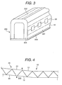
- a car body 200 is comprised of a side structure 201, a roof structure 202, a base frame 203 and an end structure body 204.
- Each of the side structure 201, the roof structure 202, and the base frame 203 is constituted by joining plural extruded frame members.
- the longitudinal direction of these extruded frame members is in the longitudinal direction of the car body 200.
- the extruded frame member is a hollow frame member made of an aluminum alloy.
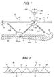
- the hollow frame members 10 and 20 are each comprised of two sheet face plates 11, 12 and 21, 22 and plural truss ribs 13 and 23.
- the two sheet face plates 11 and 12 (and likewise the two sheet face plates 21 and 22) are substantially parallel.
- the pitch of the truss formed by ribs 13 and 23 is the same.
- the truss is constituted by the ribs 13 and 23 and a center line of a plate thickness of the face plates 11 and 12 and the face plates 21 and 22.
- An apex exists at a side of the face plates 11 and 12 and the face plates 21 and 22. The apex is shown by a filled circle.
- the rails 19 and 29 are comprised of two L shape members, and are used for installing the parts and apparatus such as interior mounting sheets and seats, etc.
- a rib 13A which constitutes one side of the truss.
- the rib 13A connects the end of the face plate 11 with the end of the face plate 12.
- a rib 13B connects the end of the face plate 11 and an intermediate point of the face plate 12.
- the end portion of the face plate 21 of the hollow frame member 20 projects further laterally, towards the adjacent hollow frame member 10, than the end portion of the face plate 22. There is no rib directly connecting the ends of the face plates 21 and 22.
- An inner side of the end portion of the face plate 21 overlaps and lies on a seat 17 which is projected from the rib 13A.
- the seat 17 is provided at the thickening or rib 17A which is provided in the vicinity of the cross-point of the ribs 13A and 13B.
- An inner side of the end portion of the face plate 12 overlaps and underlies a seat 27 which projects from the end portion of the face plate 22.
- an isosceles triangle truss shape is constituted by the ribs 13A, 23B and the face plate 21.
- the dimension of this truss shape is the same as that of the other truss shapes.
- Raised portions 15, 25, 16, 26 are provided at the outer faces of the abutted portions and all have the same height and width. These abutted portions are subjected to friction stir joining. Plate thickness of the ribs 13A, 13B and 23B is greater than that of other ribs 13 and 23.
- the abutment faces are on vertical lines (lines normal to the face plates) at the apex of the truss shapes which are constituted by the ribs 13A, 13B and 23B and the plate faces 12 and 22. From the view point of accuracy of positioning of the rotary tool 250, in practice the axis of the rotary tool 250 is positioned at a vertical line or plane in the vicinity of the apex of the truss shape.
- the hollow frame members 10 and 20 are mounted on a bed 240 with the face plates 12 and 22 downward. From the upper side, the rotary tool 250 is inserted into the joint portion and the friction stir joining is carried out.
- Abutted faces 15b and 26b of the raised portions 15, 25, 16, 26 are perpendicular to the plate faces 11 and 22.
- a recessed or reentrant portion is constituted by the vertical faces 15b and 26b and horizontal faces of the seats 17 and 27. This recessed portion is opened to a face along to the face plates 11 and 22 and an end portion side of the hollow frame members 10 and 20.
- the abutted faces 15b and 26b are orthogonal to the face plates 11 and 12 and the face plates 21 and 22. Namely, the abutted faces extend along to a normal line of the face plates.
- the abutted faces 15b and 26b extend in the thickness direction of the hollow frame members 10 and 20.
- the abutted faces 15b and 26b are positioned in each case toward the opposite end portion of the respective hollow frame member 10, 20 from the normal line which passes through the apex of the truss shape.
- the abutted faces 15b, 26b lie on the normal line which passes through the apex of the truss shape, and in a case where the end portions of other face plates 21 and 12 are short (within an allowable error), the insertion position of the rotary tool 250 approaches toward other face plates side. In this case, there is a possibility that the load on the rib at the approached side becomes excessive. If the widths of the two raised portions 15 and 25 (16 and 26) are detected, then the axis of the rotary tool 250 is consistent with the center.
- the manufacturing method of this structure body will be explained.
- the hollow frame members 10 and 20 are mounted on and fixed to the bed 240.
- the abutted portion of the end portions of the face plates 11 and 21 (the face plates 12 and 22) are contacted or approached to each other.
- the raised portions 15 and 25 of the abutted portion of the upper face side face plates 11 and 21 are temporarily fixed by arc welding from above. The temporary welding is carried out intermittently.
- the raised portions 16 and 26 contact the bed 240.
- a vicinity of a cross-point between the rib 13B and the face plate 12 is mounted on the bed 240.
- the rotary tool 250 of a friction stir joining apparatus is inserted from the upper side into the abutted portion of the raised portions 15 and 25 and is moved along the joining line to carry out the friction stir joining.
- the axis of the rotary tool 250 is in a vertical plane. However, the axis is inclined relative to the advancing direction of the rotary tool 250, as already known. The width position of the two raised portions 15, 25 is detected and the axis of the rotary tool 250 is positioned at their center.
- the rotary tool 250 comprises a large diameter portion 252 and a small diameter portion 251 at a tip end of the large diameter portion 252.
- the tip end of the small diameter portion 251 of the rotary tool 250 is inserted deeply from the upper face of the seat 17.
- the lower end of the large diameter portion 252 of the rotary tool 250 is positioned at a level between the top surfaces of the raised portions 15 and 25 and the outer faces of the face plates 11 and 21.
- the diameter of the large diameter portion 252 of the rotary tool 250 is smaller than the combined width of the two raised portions 15 and 25.
- the small diameter portion 251 of the rotary tool 250 may have a screw shape.
- this structural body is reversed (turned over) and mounted again on the bed 240.
- temporary fixing is again carried out by arc welding.
- friction stir joining is carried out, from the upper side of the raised portions 16 and 26 by the rotary tool 250, in the same manner as above.
- the axis of the rotary tool 250 is at the apex of the truss shape formed by the two ribs 13A and 13B (the ribs 13A and 23B) or on the vertical linear line which passes the vicinity of the apex.
- the insertion force during the friction stir joining is supported by the two ribs 13A and 13B (13A and 23B).
- the plate thickness of the ribs 13A, 13B and 23B can be thin and a lightweight structure can be obtained.
- the bending of the face plates 11 and 12 can be restrained.
- the plate thickness of the ribs 13A, 13B and 23B is thicker than the plate thickness of other ribs 13 and 23.
- the bed 240 for supporting the ribs 13A, 13B and 23B By use of the bed 240 for supporting the ribs 13A, 13B and 23B, the bending of the face plate can be prevented.
- the whole structure body formed is constituted substantially as a truss structure. For this reason, the outer face bending rigidity performance can be improved and a lightweight structure can be obtained.
- the apex of the two ribs 13A and 13B may be positioned at the outer face side of the face plates 11 and 21.
- the joints in the above embodiment are carried out by friction stir joining, but alternatively one or both of the joints may be carried out by arc welding.
- arc welding since there is no load during the joining, the ribs 13A, 13B and 23B can be made thin.
- the upper face of the seat 17 and the lower face of the seat 27 may be inclined.
- the face plates 11 and 12 and the face plates 21 and 22 are parallel, but an alternative is possible where one of the face plates is inclined to the other face plate.
- Fig. 4 shows a further embodiment in which the normal line of the face plate of the joining portion is inclined to the vertical.
- One end of the hollow frame member 10 is horizontal.
- the hollow frame members 10 and 20 are mounted on the bed 240. This causes easily to the joining line of the end portion of the side structure body 201.
- the axis of the rotary tool 250 for the friction stir joining is along the normal line to the face plate. This normal line passes through the vicinity of the apex of the truss.
- An arrow mark shows the position and the direction of the rotary tool 250.
- Fig. 5 shows a further embodiment in which one frame member is a block shape member 30.
- This member 30 may or may not be hollow.
- Other parts in this embodiment are similar to those of the embodiment shown in Fig. 1.
- the seat 27 is provided at a rib connecting the raised portion 26 and the face plate 21. This rib is substantially orthogonal to the face plate 11 (along the normal line to the face plate).
- the face plate 21 lies substantially in the extension line of the face plate 11.
- Fig. 7 shows a further embodiment in which the rib 23A approaches to the end portion of the hollow frame member.
- An isosceles triangle is constituted by the center line of the rib 23A and the center line of the rib 13B.
- the axis of the rotary tool 250 is at the vertical linear line which passes through the cross-point of these two center lines. According to this structure, the insertion force can be supported by the three ribs.
- Fig. 8 shows a further embodiment in which the insertion position of the rotary tool 250 is between two cross-points.
Landscapes
- Engineering & Computer Science (AREA)
- Mechanical Engineering (AREA)
- Life Sciences & Earth Sciences (AREA)
- Wood Science & Technology (AREA)
- Pressure Welding/Diffusion-Bonding (AREA)
- Joining Of Building Structures In Genera (AREA)
- Laminated Bodies (AREA)
Abstract
Description
providing first and second hollow frame members in each of which two sheet face plates are connected in a truss manner by plural ribs, and wherein at one side edge of the member and end portion of a first one of said face plates projects further than the end portion of the second face plate, and said end portions are connected by said plural ribs of the truss, the member having an outward-facing seat at said end portion of said second face plate;
overlapping said end portion of said first face plate of a first one of said members onto said seat of the second of said hollow frame members;
overlapping said end portion of said first face plate of said second hollow frame member to said seat of said first hollow frame member; and
joining the members at the respective overlapped portions.
said end portions are connected by said ribs of said truss.
an end portion of a first one of said face plates projects further than an end portion of the second one of said face plates at a side edge of said hollow frame member; and
said end portion of said second face plate and a zone of said first face plate spaced from said end portion thereof are connected by one said rib of said truss.
preparing first and second hollow frame members in each of which two sheet face plates are connected in a truss manner by plural ribs, and wherein at one side edge of the member and end portion of a first one of said face plates projects further than the end portion of the second face plate, and said end portions are connected by said plural ribs of the truss, the member having an outward-facing seat at said end portion of said second face plate;
overlapping said end portion of said first face plate of a first one of said members onto said seat of the second of said hollow frame members;
overlapping said end portion of said first face plate of said second hollow frame member to said seat of said first hollow frame member; and
joining the members at the respective overlapped portions.
said end portions are connected by said ribs of said truss.
a raised portion standing up from the second face plate is provided at a vicinity of an apex of said truss at said end portion of said second face plate; and
said raised portion has a re-entrant formed by surfaces facing respectively outwardly from said second face plate and in the extension direction of said second face plate.
an end portion of a first one of said face plates projects further than an end portion of the second one of said face plates at a side edge of said hollow frame member; and
said end portion of said second face plate and a zone of said first face plate spaced from said end portion thereof are connected by one said rib of said truss.
said raised portion has a re-entrant formed by surfaces facing respectively outwardly from said second face plate and in the extension direction of said second face plate.
Claims (4)
- A hollow frame member (10, 20) for use in friction stir joining, comprising:wherein an end portion of a first one (12, 21) of said face plates projects further than an end portion of the second one (11, 22) of said face plates at a side edge of the member; andtwo sheet face plates (11, 12, 21, 22) connected in a truss manner by plural ribs;
said end portions are connected by said ribs of said truss;
characterised in that
a raised portion (15, 26) standing up outwardly from the second face plate (11, 22) is provided at a vicinity of an apex of said truss at said end portion of said second face plate; and
said raised portion (15, 26) has a re-entrant formed by surfaces facing respectively outwardly from said second face plate and in the extension direction of said second face plate. - A hollow frame member according to claim 1, wherein said surface of said re-entrant facing outwardly of said second face plate is aligned with said apex.
- A hollow frame member according to claim 1 or 2, wherein a raised portion (16, 25) standing up outwardly from said first face plate (12, 21) is provided at said end portion of said first face plate; and
said raised portion (16, 25) of said first face plate has a re-entrant formed by surfaces facing respectively outwardly from said first face plate and in the extension direction of said first face plate. - A hollow frame member according to claim 3, wherein said raised portion (16, 25) of said first face plate is in the vicinity of an apex of said truss.
Applications Claiming Priority (3)
| Application Number | Priority Date | Filing Date | Title |
|---|---|---|---|
| JP14913499 | 1999-05-28 | ||
| JP14913499A JP3481501B2 (en) | 1999-05-28 | 1999-05-28 | Structure and method of manufacturing the same |
| EP00304378A EP1055478B1 (en) | 1999-05-28 | 2000-05-24 | A structural body and a method of manufacturing it |
Related Parent Applications (1)
| Application Number | Title | Priority Date | Filing Date |
|---|---|---|---|
| EP00304378A Division EP1055478B1 (en) | 1999-05-28 | 2000-05-24 | A structural body and a method of manufacturing it |
Publications (3)
| Publication Number | Publication Date |
|---|---|
| EP1375051A2 true EP1375051A2 (en) | 2004-01-02 |
| EP1375051A3 EP1375051A3 (en) | 2004-01-21 |
| EP1375051B1 EP1375051B1 (en) | 2006-09-27 |
Family
ID=15468496
Family Applications (2)
| Application Number | Title | Priority Date | Filing Date |
|---|---|---|---|
| EP00304378A Expired - Lifetime EP1055478B1 (en) | 1999-05-28 | 2000-05-24 | A structural body and a method of manufacturing it |
| EP03021059A Expired - Lifetime EP1375051B1 (en) | 1999-05-28 | 2000-05-24 | A structural body for use in friction stir joining method |
Family Applications Before (1)
| Application Number | Title | Priority Date | Filing Date |
|---|---|---|---|
| EP00304378A Expired - Lifetime EP1055478B1 (en) | 1999-05-28 | 2000-05-24 | A structural body and a method of manufacturing it |
Country Status (8)
| Country | Link |
|---|---|
| US (1) | US6413610B1 (en) |
| EP (2) | EP1055478B1 (en) |
| JP (1) | JP3481501B2 (en) |
| KR (1) | KR100415454B1 (en) |
| CN (1) | CN1174829C (en) |
| AU (1) | AU750585B2 (en) |
| DE (2) | DE60013027T2 (en) |
| TW (1) | TW446597B (en) |
Cited By (2)
| Publication number | Priority date | Publication date | Assignee | Title |
|---|---|---|---|---|
| CN100411803C (en) * | 2005-12-01 | 2008-08-20 | 安富盛金属科技(句容)有限公司 | How to make a metal truss |
| CN101032784B (en) * | 2006-03-08 | 2011-05-11 | 萨帕铝型材股份公司 | Adjustable overlap joint and structure produced thereby |
Families Citing this family (42)
| Publication number | Priority date | Publication date | Assignee | Title |
|---|---|---|---|---|
| US6581819B1 (en) * | 1996-03-19 | 2003-06-24 | Hitachi, Ltd. | Panel structure, a friction stir welding method, and a panel |
| JP3070735B2 (en) * | 1997-07-23 | 2000-07-31 | 株式会社日立製作所 | Friction stir welding method |
| JP3288669B2 (en) | 2000-01-25 | 2002-06-04 | 川崎重工業株式会社 | Joint structure of hollow material with friction stir welding |
| CN1191144C (en) | 2000-05-08 | 2005-03-02 | 布莱阿姆青年大学 | Superabrasive tools and methods for friction stir welding |
| US7011350B2 (en) | 2000-11-22 | 2006-03-14 | Alcoa, Inc. | Flash welded joint structure and method for making a joint structure |
| US6598923B2 (en) * | 2000-11-22 | 2003-07-29 | Alcoa Inc. | Joint structure and method for making a joint structure |
| JP3675714B2 (en) * | 2000-12-20 | 2005-07-27 | 株式会社日立製作所 | Railway vehicle wife manufacturing method and rail car body |
| JP3761786B2 (en) * | 2001-01-17 | 2006-03-29 | 株式会社日立製作所 | Friction stir welding method and apparatus |
| JP3751215B2 (en) * | 2001-04-16 | 2006-03-01 | 株式会社日立製作所 | Friction stir welding method |
| US6732901B2 (en) | 2001-06-12 | 2004-05-11 | Brigham Young University Technology Transfer Office | Anvil for friction stir welding high temperature materials |
| US7360343B1 (en) * | 2002-05-07 | 2008-04-22 | Daw Technologies, Inc. | Raised access floor |
| US7127865B2 (en) * | 2002-10-11 | 2006-10-31 | Douglas Robert B | Modular structure for building panels and methods of making and using same |
| US7270257B2 (en) | 2003-01-30 | 2007-09-18 | Sii Megadiamond, Inc. | Out-of-position friction stir welding of high melting temperature alloys |
| US7530486B2 (en) | 2003-05-05 | 2009-05-12 | Sii Megadiamond, Inc. | Applications of friction stir welding using a superabrasive tool |
| WO2005084162A2 (en) | 2003-08-04 | 2005-09-15 | Smith International, Inc. | Crack repair using friction stir welding on materials including metal matrix composites, ferrous alloys, non-ferrous alloys, and superalloys |
| US20050070374A1 (en) * | 2003-09-29 | 2005-03-31 | Technology Licensing, Llc | Enhanced golf club performance via friction stir processing |
| US20060032333A1 (en) | 2004-03-24 | 2006-02-16 | Steel Russell J | Solid state processing of industrial blades, edges and cutting elements |
| US20100078224A1 (en) | 2004-05-21 | 2010-04-01 | Smith International, Inc. | Ball hole welding using the friction stir welding (fsw) process |
| CA2582732C (en) | 2004-10-05 | 2012-09-11 | Sii Megadiamond, Inc. | Expandable mandrel for use in friction stir welding |
| US9511446B2 (en) | 2014-12-17 | 2016-12-06 | Aeroprobe Corporation | In-situ interlocking of metals using additive friction stir processing |
| US20080041921A1 (en) | 2005-09-26 | 2008-02-21 | Kevin Creehan | Friction stir fabrication |
| US9511445B2 (en) | 2014-12-17 | 2016-12-06 | Aeroprobe Corporation | Solid state joining using additive friction stir processing |
| US8632850B2 (en) | 2005-09-26 | 2014-01-21 | Schultz-Creehan Holdings, Inc. | Friction fabrication tools |
| US9266191B2 (en) | 2013-12-18 | 2016-02-23 | Aeroprobe Corporation | Fabrication of monolithic stiffening ribs on metallic sheets |
| US8875976B2 (en) | 2005-09-26 | 2014-11-04 | Aeroprobe Corporation | System for continuous feeding of filler material for friction stir welding, processing and fabrication |
| US8550326B2 (en) | 2005-10-05 | 2013-10-08 | Megastir Technologies Llc | Expandable mandrel for use in friction stir welding |
| US8056797B2 (en) | 2005-10-05 | 2011-11-15 | Megastir Technologies | Expandable mandrel for use in friction stir welding |
| DE102005048001B4 (en) * | 2005-10-06 | 2007-06-14 | Euro-Composites S.A., Zone Industrielle | connecting element |
| US20070175132A1 (en) * | 2006-01-17 | 2007-08-02 | Daw Technologies, Inc. | Raised access floor |
| JP2007201177A (en) | 2006-01-26 | 2007-08-09 | Canon Inc | Top plate, positioning apparatus, exposure apparatus and device manufacturing method |
| JP4266024B2 (en) * | 2006-03-28 | 2009-05-20 | 株式会社日立製作所 | Rail vehicle, manufacturing method thereof, and hollow shape material used therefor |
| CN100462179C (en) * | 2006-05-18 | 2009-02-18 | 中南大学 | A welding device and method |
| KR100971736B1 (en) * | 2009-04-03 | 2010-07-21 | 이재호 | Shear reinforcement with dual anchorage function each up and down |
| CA2779075C (en) | 2009-11-02 | 2016-05-10 | Megastir Technologies Llc | Out of position friction stir welding of casing and small diameter tubing or pipe |
| WO2013002869A2 (en) | 2011-04-07 | 2013-01-03 | Schultz-Creehan Holdings, Inc. | System for continuous feeding of filler material for friction stir fabrication and self-reacting friction stir welding tool |
| US8590767B2 (en) * | 2011-06-21 | 2013-11-26 | Research Institute Of Industrial Science & Technology | Method for welding hollow structure |
| KR20140051248A (en) * | 2011-07-19 | 2014-04-30 | 마그나 인터내셔널 인코포레이티드 | Method of welding work pieces together |
| JP5612135B2 (en) * | 2013-01-08 | 2014-10-22 | 日本車輌製造株式会社 | Friction stir welding tool, double skin panel assembly manufacturing method, and railcar structure |
| JP6178703B2 (en) * | 2013-11-13 | 2017-08-09 | 三菱日立パワーシステムズ株式会社 | Method for manufacturing steam turbine rotor blade with anticorrosion piece |
| FR3033846B1 (en) * | 2015-03-19 | 2019-05-10 | Arianegroup Sas | FLEXIBLE CONNECTION AND FLEXIBLE CONNECTION FOR SUCH ASSEMBLY |
| WO2019089764A1 (en) | 2017-10-31 | 2019-05-09 | Aeroprobe Corporation | Solid-state additive manufacturing system and material compositions and structures |
| CN115556783A (en) * | 2022-10-20 | 2023-01-03 | 北京轨道交通技术装备集团有限公司 | Modular end wall structure of subway vehicle and manufacturing method thereof |
Family Cites Families (11)
| Publication number | Priority date | Publication date | Assignee | Title |
|---|---|---|---|---|
| US4337708A (en) * | 1980-04-11 | 1982-07-06 | Pullman Incorporated | Railway car superstructure frame |
| US4653683A (en) * | 1984-12-24 | 1987-03-31 | The Budd Company | Means and method for securing a tubular member to a side frame of a rail car truck |
| FR2590220B1 (en) * | 1985-11-19 | 1987-12-31 | Schneider Jeumont Rail Sa | METHOD OF MECHANICAL WELDING OF RAIL VEHICLE CHASSIS ELEMENTS |
| US5098007A (en) * | 1989-01-18 | 1992-03-24 | Hitachi, Ltd. | Method of manufacturing a vehicle body |
| US5199632A (en) * | 1989-06-30 | 1993-04-06 | Hitachi. Ltd. | Railway car body structures and methods of making them |
| US5351625A (en) * | 1993-07-12 | 1994-10-04 | Acf Industries | Weld support for railway tank car underbody construction |
| US5651154A (en) * | 1995-11-13 | 1997-07-29 | Reynolds Metals Company | Modular bridge deck system consisting of hollow extruded aluminum elements |
| JP3807766B2 (en) | 1996-02-20 | 2006-08-09 | 株式会社日立製作所 | Manufacturing method of railway vehicle structure |
| US6581819B1 (en) | 1996-03-19 | 2003-06-24 | Hitachi, Ltd. | Panel structure, a friction stir welding method, and a panel |
| JP3070735B2 (en) * | 1997-07-23 | 2000-07-31 | 株式会社日立製作所 | Friction stir welding method |
| US6051325A (en) * | 1997-12-23 | 2000-04-18 | Mcdonnell Douglas Corporation | Joining of machined sandwich assemblies by friction stir welding |
-
1999
- 1999-05-28 JP JP14913499A patent/JP3481501B2/en not_active Expired - Fee Related
-
2000
- 2000-03-28 US US09/536,641 patent/US6413610B1/en not_active Expired - Fee Related
- 2000-03-31 TW TW089106114A patent/TW446597B/en not_active IP Right Cessation
- 2000-05-17 AU AU35348/00A patent/AU750585B2/en not_active Ceased
- 2000-05-24 EP EP00304378A patent/EP1055478B1/en not_active Expired - Lifetime
- 2000-05-24 DE DE60013027T patent/DE60013027T2/en not_active Expired - Lifetime
- 2000-05-24 EP EP03021059A patent/EP1375051B1/en not_active Expired - Lifetime
- 2000-05-24 CN CNB001089579A patent/CN1174829C/en not_active Expired - Fee Related
- 2000-05-24 DE DE60031009T patent/DE60031009T2/en not_active Expired - Lifetime
- 2000-05-26 KR KR10-2000-0028599A patent/KR100415454B1/en not_active Expired - Fee Related
Cited By (2)
| Publication number | Priority date | Publication date | Assignee | Title |
|---|---|---|---|---|
| CN100411803C (en) * | 2005-12-01 | 2008-08-20 | 安富盛金属科技(句容)有限公司 | How to make a metal truss |
| CN101032784B (en) * | 2006-03-08 | 2011-05-11 | 萨帕铝型材股份公司 | Adjustable overlap joint and structure produced thereby |
Also Published As
| Publication number | Publication date |
|---|---|
| AU3534800A (en) | 2000-11-30 |
| AU750585B2 (en) | 2002-07-25 |
| JP2000334581A (en) | 2000-12-05 |
| DE60013027D1 (en) | 2004-09-23 |
| EP1055478A1 (en) | 2000-11-29 |
| DE60031009D1 (en) | 2006-11-09 |
| CN1174829C (en) | 2004-11-10 |
| EP1375051B1 (en) | 2006-09-27 |
| JP3481501B2 (en) | 2003-12-22 |
| TW446597B (en) | 2001-07-21 |
| DE60013027T2 (en) | 2005-08-18 |
| CN1275452A (en) | 2000-12-06 |
| KR100415454B1 (en) | 2004-01-24 |
| EP1055478B1 (en) | 2004-08-18 |
| US6413610B1 (en) | 2002-07-02 |
| DE60031009T2 (en) | 2007-01-04 |
| EP1375051A3 (en) | 2004-01-21 |
| KR20010014974A (en) | 2001-02-26 |
Similar Documents
| Publication | Publication Date | Title |
|---|---|---|
| EP1055478B1 (en) | A structural body and a method of manufacturing it | |
| US6532712B2 (en) | Structural body and method of manufacture thereof | |
| EP1103334B1 (en) | Friction stir joining method | |
| US6582831B2 (en) | Friction stir welded body and frame member therefor | |
| EP1123770B1 (en) | Friction stir joining method and structural body | |
| US6599641B1 (en) | Structural body formed by friction stir welding of hollow extruded frame members | |
| US20010004992A1 (en) | Method of friction stir welding structural body, structural body, and extruded material | |
| US20020119336A1 (en) | Method of friction stir welding structural body, structural body, and extruded material | |
| JP3459197B2 (en) | Hollow profile for friction stir welding | |
| AU2002301555B2 (en) | A frame member | |
| JP4494671B2 (en) | Structure and manufacturing method thereof | |
| JP3840029B2 (en) | Hollow profile | |
| EP1236532A1 (en) | Method of friction stir welding structural body, structural body, and extruded material | |
| AU2320401A (en) | Method of friction stir welding structural body, structural body, and extruded material |
Legal Events
| Date | Code | Title | Description |
|---|---|---|---|
| PUAI | Public reference made under article 153(3) epc to a published international application that has entered the european phase |
Free format text: ORIGINAL CODE: 0009012 |
|
| PUAL | Search report despatched |
Free format text: ORIGINAL CODE: 0009013 |
|
| 17P | Request for examination filed |
Effective date: 20031006 |
|
| AC | Divisional application: reference to earlier application |
Ref document number: 1055478 Country of ref document: EP Kind code of ref document: P |
|
| AK | Designated contracting states |
Kind code of ref document: A2 Designated state(s): DE FR GB IT SE |
|
| AK | Designated contracting states |
Kind code of ref document: A3 Designated state(s): DE FR GB IT SE |
|
| RIC1 | Information provided on ipc code assigned before grant |
Ipc: 7B 61D 17/04 B Ipc: 7E 04C 2/54 B Ipc: 7B 23K 20/12 A Ipc: 7B 23K 31/00 B |
|
| RIN1 | Information on inventor provided before grant (corrected) |
Inventor name: NAKAMURA, HIDEYUKI Inventor name: MAKINO, TOSHIAKI Inventor name: SAGAWA, TOSHIAKI Inventor name: KAWASAKI, TAKESHI |
|
| AKX | Designation fees paid |
Designated state(s): DE FR GB IT SE |
|
| 17Q | First examination report despatched |
Effective date: 20050223 |
|
| GRAP | Despatch of communication of intention to grant a patent |
Free format text: ORIGINAL CODE: EPIDOSNIGR1 |
|
| GRAS | Grant fee paid |
Free format text: ORIGINAL CODE: EPIDOSNIGR3 |
|
| GRAA | (expected) grant |
Free format text: ORIGINAL CODE: 0009210 |
|
| AC | Divisional application: reference to earlier application |
Ref document number: 1055478 Country of ref document: EP Kind code of ref document: P |
|
| AK | Designated contracting states |
Kind code of ref document: B1 Designated state(s): DE FR GB IT SE |
|
| PG25 | Lapsed in a contracting state [announced via postgrant information from national office to epo] |
Ref country code: IT Free format text: LAPSE BECAUSE OF FAILURE TO SUBMIT A TRANSLATION OF THE DESCRIPTION OR TO PAY THE FEE WITHIN THE PRESCRIBED TIME-LIMIT;WARNING: LAPSES OF ITALIAN PATENTS WITH EFFECTIVE DATE BEFORE 2007 MAY HAVE OCCURRED AT ANY TIME BEFORE 2007. THE CORRECT EFFECTIVE DATE MAY BE DIFFERENT FROM THE ONE RECORDED. Effective date: 20060927 |
|
| REG | Reference to a national code |
Ref country code: GB Ref legal event code: FG4D |
|
| REF | Corresponds to: |
Ref document number: 60031009 Country of ref document: DE Date of ref document: 20061109 Kind code of ref document: P |
|
| REG | Reference to a national code |
Ref country code: SE Ref legal event code: TRGR |
|
| ET | Fr: translation filed | ||
| PLBE | No opposition filed within time limit |
Free format text: ORIGINAL CODE: 0009261 |
|
| STAA | Information on the status of an ep patent application or granted ep patent |
Free format text: STATUS: NO OPPOSITION FILED WITHIN TIME LIMIT |
|
| 26N | No opposition filed |
Effective date: 20070628 |
|
| PGFP | Annual fee paid to national office [announced via postgrant information from national office to epo] |
Ref country code: DE Payment date: 20120516 Year of fee payment: 13 |
|
| PGFP | Annual fee paid to national office [announced via postgrant information from national office to epo] |
Ref country code: FR Payment date: 20120608 Year of fee payment: 13 Ref country code: GB Payment date: 20120523 Year of fee payment: 13 Ref country code: SE Payment date: 20120511 Year of fee payment: 13 |
|
| PGFP | Annual fee paid to national office [announced via postgrant information from national office to epo] |
Ref country code: IT Payment date: 20120519 Year of fee payment: 13 |
|
| REG | Reference to a national code |
Ref country code: SE Ref legal event code: EUG |
|
| GBPC | Gb: european patent ceased through non-payment of renewal fee |
Effective date: 20130524 |
|
| PG25 | Lapsed in a contracting state [announced via postgrant information from national office to epo] |
Ref country code: DE Free format text: LAPSE BECAUSE OF NON-PAYMENT OF DUE FEES Effective date: 20131203 Ref country code: SE Free format text: LAPSE BECAUSE OF NON-PAYMENT OF DUE FEES Effective date: 20130525 |
|
| PG25 | Lapsed in a contracting state [announced via postgrant information from national office to epo] |
Ref country code: IT Free format text: LAPSE BECAUSE OF NON-PAYMENT OF DUE FEES Effective date: 20130524 |
|
| REG | Reference to a national code |
Ref country code: FR Ref legal event code: ST Effective date: 20140131 |
|
| REG | Reference to a national code |
Ref country code: DE Ref legal event code: R119 Ref document number: 60031009 Country of ref document: DE Effective date: 20131203 |
|
| PG25 | Lapsed in a contracting state [announced via postgrant information from national office to epo] |
Ref country code: GB Free format text: LAPSE BECAUSE OF NON-PAYMENT OF DUE FEES Effective date: 20130524 |
|
| PG25 | Lapsed in a contracting state [announced via postgrant information from national office to epo] |
Ref country code: FR Free format text: LAPSE BECAUSE OF NON-PAYMENT OF DUE FEES Effective date: 20130531 |