EP1374967B1 - Plattenförmiger Filtrationskörper - Google Patents
Plattenförmiger Filtrationskörper Download PDFInfo
- Publication number
- EP1374967B1 EP1374967B1 EP03012592A EP03012592A EP1374967B1 EP 1374967 B1 EP1374967 B1 EP 1374967B1 EP 03012592 A EP03012592 A EP 03012592A EP 03012592 A EP03012592 A EP 03012592A EP 1374967 B1 EP1374967 B1 EP 1374967B1
- Authority
- EP
- European Patent Office
- Prior art keywords
- mould cavity
- compression
- filtration
- channels
- plate
- Prior art date
- Legal status (The legal status is an assumption and is not a legal conclusion. Google has not performed a legal analysis and makes no representation as to the accuracy of the status listed.)
- Expired - Lifetime
Links
- 238000001914 filtration Methods 0.000 title claims description 61
- ZZUFCTLCJUWOSV-UHFFFAOYSA-N furosemide Chemical compound C1=C(Cl)C(S(=O)(=O)N)=CC(C(O)=O)=C1NCC1=CC=CO1 ZZUFCTLCJUWOSV-UHFFFAOYSA-N 0.000 title 1
- 238000007906 compression Methods 0.000 claims description 31
- 239000000843 powder Substances 0.000 claims description 19
- 230000006835 compression Effects 0.000 claims description 18
- 238000000034 method Methods 0.000 claims description 16
- 239000012466 permeate Substances 0.000 claims description 16
- 239000000463 material Substances 0.000 claims description 14
- 239000011148 porous material Substances 0.000 claims description 10
- 238000003825 pressing Methods 0.000 claims description 8
- 239000013067 intermediate product Substances 0.000 claims description 4
- 238000004519 manufacturing process Methods 0.000 claims description 4
- 239000002245 particle Substances 0.000 claims description 4
- 238000007599 discharging Methods 0.000 claims 1
- 238000000605 extraction Methods 0.000 claims 1
- 238000002791 soaking Methods 0.000 claims 1
- 238000000465 moulding Methods 0.000 description 5
- 239000012528 membrane Substances 0.000 description 4
- 229910010293 ceramic material Inorganic materials 0.000 description 3
- 238000005056 compaction Methods 0.000 description 3
- 230000002093 peripheral effect Effects 0.000 description 3
- 239000000919 ceramic Substances 0.000 description 2
- 230000006378 damage Effects 0.000 description 2
- 230000000694 effects Effects 0.000 description 2
- 239000000706 filtrate Substances 0.000 description 2
- 239000000126 substance Substances 0.000 description 2
- VYPSYNLAJGMNEJ-UHFFFAOYSA-N Silicium dioxide Chemical compound O=[Si]=O VYPSYNLAJGMNEJ-UHFFFAOYSA-N 0.000 description 1
- 238000004140 cleaning Methods 0.000 description 1
- 238000004891 communication Methods 0.000 description 1
- 239000002131 composite material Substances 0.000 description 1
- 230000003111 delayed effect Effects 0.000 description 1
- 238000004512 die casting Methods 0.000 description 1
- 238000005553 drilling Methods 0.000 description 1
- 230000009969 flowable effect Effects 0.000 description 1
- 239000007789 gas Substances 0.000 description 1
- 239000008187 granular material Substances 0.000 description 1
- 239000007788 liquid Substances 0.000 description 1
- 239000002184 metal Substances 0.000 description 1
- 229910052751 metal Inorganic materials 0.000 description 1
- 229910021426 porous silicon Inorganic materials 0.000 description 1
- 239000003870 refractory metal Substances 0.000 description 1
- 230000003716 rejuvenation Effects 0.000 description 1
- 239000012465 retentate Substances 0.000 description 1
- 235000012239 silicon dioxide Nutrition 0.000 description 1
- 239000000377 silicon dioxide Substances 0.000 description 1
- 238000005245 sintering Methods 0.000 description 1
- 239000007787 solid Substances 0.000 description 1
- 238000009423 ventilation Methods 0.000 description 1
Images





Classifications
-
- B—PERFORMING OPERATIONS; TRANSPORTING
- B01—PHYSICAL OR CHEMICAL PROCESSES OR APPARATUS IN GENERAL
- B01D—SEPARATION
- B01D67/00—Processes specially adapted for manufacturing semi-permeable membranes for separation processes or apparatus
- B01D67/0039—Inorganic membrane manufacture
- B01D67/0041—Inorganic membrane manufacture by agglomeration of particles in the dry state
- B01D67/00411—Inorganic membrane manufacture by agglomeration of particles in the dry state by sintering
-
- B—PERFORMING OPERATIONS; TRANSPORTING
- B01—PHYSICAL OR CHEMICAL PROCESSES OR APPARATUS IN GENERAL
- B01D—SEPARATION
- B01D33/00—Filters with filtering elements which move during the filtering operation
- B01D33/15—Filters with filtering elements which move during the filtering operation with rotary plane filtering surfaces
- B01D33/21—Filters with filtering elements which move during the filtering operation with rotary plane filtering surfaces with hollow filtering discs transversely mounted on a hollow rotary shaft
-
- B—PERFORMING OPERATIONS; TRANSPORTING
- B01—PHYSICAL OR CHEMICAL PROCESSES OR APPARATUS IN GENERAL
- B01D—SEPARATION
- B01D33/00—Filters with filtering elements which move during the filtering operation
- B01D33/15—Filters with filtering elements which move during the filtering operation with rotary plane filtering surfaces
- B01D33/21—Filters with filtering elements which move during the filtering operation with rotary plane filtering surfaces with hollow filtering discs transversely mounted on a hollow rotary shaft
- B01D33/23—Construction of discs or component sectors thereof
-
- B—PERFORMING OPERATIONS; TRANSPORTING
- B01—PHYSICAL OR CHEMICAL PROCESSES OR APPARATUS IN GENERAL
- B01D—SEPARATION
- B01D33/00—Filters with filtering elements which move during the filtering operation
- B01D33/35—Filters with filtering elements which move during the filtering operation with multiple filtering elements characterised by their mutual disposition
- B01D33/37—Filters with filtering elements which move during the filtering operation with multiple filtering elements characterised by their mutual disposition in parallel connection
-
- B—PERFORMING OPERATIONS; TRANSPORTING
- B01—PHYSICAL OR CHEMICAL PROCESSES OR APPARATUS IN GENERAL
- B01D—SEPARATION
- B01D33/00—Filters with filtering elements which move during the filtering operation
- B01D33/35—Filters with filtering elements which move during the filtering operation with multiple filtering elements characterised by their mutual disposition
- B01D33/37—Filters with filtering elements which move during the filtering operation with multiple filtering elements characterised by their mutual disposition in parallel connection
- B01D33/39—Filters with filtering elements which move during the filtering operation with multiple filtering elements characterised by their mutual disposition in parallel connection concentrically or coaxially
-
- B—PERFORMING OPERATIONS; TRANSPORTING
- B01—PHYSICAL OR CHEMICAL PROCESSES OR APPARATUS IN GENERAL
- B01D—SEPARATION
- B01D33/00—Filters with filtering elements which move during the filtering operation
- B01D33/58—Handling the filter cake in the filter for purposes other than for regenerating the filter cake remaining on the filtering element
- B01D33/68—Retarding cake deposition on the filter during the filtration period, e.g. using stirrers
-
- B—PERFORMING OPERATIONS; TRANSPORTING
- B01—PHYSICAL OR CHEMICAL PROCESSES OR APPARATUS IN GENERAL
- B01D—SEPARATION
- B01D63/00—Apparatus in general for separation processes using semi-permeable membranes
- B01D63/08—Flat membrane modules
- B01D63/081—Manufacturing thereof
-
- B—PERFORMING OPERATIONS; TRANSPORTING
- B01—PHYSICAL OR CHEMICAL PROCESSES OR APPARATUS IN GENERAL
- B01D—SEPARATION
- B01D63/00—Apparatus in general for separation processes using semi-permeable membranes
- B01D63/16—Rotary, reciprocated or vibrated modules
-
- B—PERFORMING OPERATIONS; TRANSPORTING
- B01—PHYSICAL OR CHEMICAL PROCESSES OR APPARATUS IN GENERAL
- B01D—SEPARATION
- B01D69/00—Semi-permeable membranes for separation processes or apparatus characterised by their form, structure or properties; Manufacturing processes specially adapted therefor
- B01D69/10—Supported membranes; Membrane supports
-
- B—PERFORMING OPERATIONS; TRANSPORTING
- B01—PHYSICAL OR CHEMICAL PROCESSES OR APPARATUS IN GENERAL
- B01D—SEPARATION
- B01D71/00—Semi-permeable membranes for separation processes or apparatus characterised by the material; Manufacturing processes specially adapted therefor
- B01D71/02—Inorganic material
-
- B—PERFORMING OPERATIONS; TRANSPORTING
- B01—PHYSICAL OR CHEMICAL PROCESSES OR APPARATUS IN GENERAL
- B01D—SEPARATION
- B01D2323/00—Details relating to membrane preparation
- B01D2323/24—Use of template or surface directing agents [SDA]
Definitions
- the invention relates to a method for producing a plate-shaped filtration body - hereinafter referred to as "filtration plate”.
- Such filtration plates may for example have the shape of a circular disk. They consist for example of a filter membrane material, for example of porous silicon dioxide.
- a device for the filtration of flowable media may comprise a plurality of such filtration plates. The filtration plates are arranged coaxially with each other and have a mutual distance. A hollow shaft is passed through all the filtration plates. The individual filtration plate has in its interior permeate Ableitkanäle which are in conductive communication with the interior of the hollow shaft.
- the filtration plates are generated as follows:
- a sinterable powder In a mold cavity, first a first amount of a sinterable powder is poured. In this position, an intermediate body is applied, which consists of a volatilized under pressure or under heat material, for example, made of cardboard. On this intermediate body another layer of sinterable powder is poured. The whole thing is condensed in the mold nest. The material of the intermediate body volatilizes, and there remains a cavity which forms said permeate drainage channels.
- filtration plates of the type mentioned special requirements are made. These relate in particular to the strength of the individual plate. Thus, the filtration plate during operation according to the considerable stresses withstand currents in a filtration plant.
- the single plate should also be sufficiently strong in itself, so that, for example, in the structure of several layers of the composite between such layers is permanent.
- the plates should be easy to assemble into plate packages of the type mentioned. They should be easy to produce and inexpensive. They should be easy to handle, as far as the assembly and disassembly is concerned.
- the invention has for its object to make filtration plates such that they meet the requirements mentioned to a greater extent than the previously known filtration plates.
- such plates should be gap-resistant, that is, have no cracks, especially not in the area of the permeate drainage channels.
- a method for producing a plate-shaped filtration body (filtration plate) from a sinterable powder comprises the following process steps: It is introduced a first quantum sinterable powder in a mold cavity whose inner contour approximately corresponds to the outer contour of the support body. Then, an intermediate body is applied to the first quantum, which consists of a volatilized under pressure and / or heat material. After that, a second quantity of sinterable powder is poured onto the intermediate body.
- the two quanta are formed with the intermediate body therebetween by compression to an intermediate product, wherein the intermediate product is sintered, optionally brought by mechanical processing in the final form and coated with a filtering layer.
- a negative pressure is applied to the mold cavity prior to compacting and / or during the compression, or the compression is carried out intermittently.
- the invention is based on the following: It is known that the sinterable powder contains air before and during compression. The air is between the particles of the powder.
- the device has two hollow shafts 1, 2.
- the two hollow shafts are each assigned a plate pack 3 or 4.
- the filtration plates are arranged parallel to each other.
- the filtration plates 3 are rotatably connected to the hollow shaft 1, and the filtration plates 4 with the hollow shaft second
- the filtration plates 3, 4 are made of porous ceramic material with a ceramic membrane forming the outer filtration plate surface. Like from the FIGS. 4 and 5 recognizable, they are provided with channels. Since the FIGS. 4 and 5 refer to a segment of the filtration plates 3, you can see there the channels 3.1. The channels are arranged radially. They thus extend from the peripheral region of the segment to the hollow shaft 3 and communicate with the interior thereof in a conductive connection. Certain deviations from the radial direction are possible.
- the following variant is conceivable: There are two or more packages provided. At least one of these has a hollow shaft and carries active filtration plates. It can also be a number of packages equipped with dummy plates, with or without a hollow shaft.
- the respective hollow shaft and the associated filtration plates are referred to herein as a "package".
- the package formed from the hollow shaft 1 and filtration plate 3 is exactly the same design and constructed the same, as the built-up of hollow shaft 2 and the filtration plates 4 package.
- the filtration plates of one package could have a larger diameter than the filtration plates of the other package.
- the filtration plates are circular. Again, deviations would be possible. For example, an oval shape would be considered.
- the two packages are arranged in a container 5.
- the container 5 has an inlet 5.1 and an outlet 5.2.
- the two hollow shafts 1, 2 have at their upper ends outlets 1.1 and 1.2 respectively.
- the device works as follows: The container is fed through inlet 5.1, the medium to be treated. The filtrate / permeate passes through the pores of the ceramic material of the ceramic discs in the channels 3.1 and 4.1- the latter not shown here. The permeate passes from the channels into the interior of the two hollow shafts 1, 2 and is discharged at the outlets 1.1, 1.2.
- Another possibility is to provide an even larger number of packages within one and the same device. For example, one package may be centrally located while the remaining packages are concentrically grouped around the central package.
- the individual filtration plate 3, 4 can be constructed from a plurality of segments.
- the circular segment shown here is thus part of a filtration plate 3.
- the filtration plates can also be constructed entirely from a single part.
- Filtration plates 3 shown have permeate channels 3.1 certain configurations. As you can see, they are rejuvenating Channels seen from outside to inside in this plan view. They are thus wedge-shaped. In general, the permeate channels will extend parallel or approximately parallel or approximately parallel to the side surfaces of the filtration plate 3,4. In general, they extend to the center of the relevant filtration plate, which has a bore there, and terminate in the peripheral region in front of the outer edge of the filtration plate 3, 4th
- the channels 3.1 are in turn wedge-shaped, however, each have a recess in the radially outer region.
- the channel thus has a kind Astgabelform in this plan view.
- this channel design is that the permeate thereby has short paths to travel to the permeate discharge channel.
- FIG. 8 Another effect is achieved by the in FIG. 8 Channel design shown - this time seen in an axial section through the plate package. As you can see, the canal tapers again from outside to inside. The meaning is as follows: In the case of a rotating filtration plate, the permeate in the outer region of the filtration plate is under slightly elevated pressure. The described design of the channel compensates for this increased pressure by the wall thickness decrease. Finally, the channels can be designed such that the flow rate of the filtrate / permeate is constant on its way to the hollow shaft.
- FIG. 9 recognizes that the filtration plate 3 is designed streamlined in its peripheral region, such as the type of flowed edge of an airfoil. It has been shown that the wear of the membrane is thereby significantly minimized.
- Filtration plate 3 shown is constructed as follows: it comprises two support body halves 3.2, 3.3. These are joined together along a plane 3.4.
- the two support body halves 3.2, 3.3 are at least partially coated on their outer sides with a membrane filter layer 3.5.
- the level 3.4 is of fundamental importance for the function of the filtration plate. It is namely desirable that the two support body halves 3.2, 3.3 in the plane 3.4 enter into an intimate connection with each other, and that there are no cracks, crevices or air pockets in this level.
- FIG. 11 shows an essential part of an apparatus for carrying out the method.
- One recognizes a piston 21 with an end face 21.1. It also recognizes a cylinder liner 20 in which the piston 21 is guided.
- sinterable, powdery material is applied to the end face 21.1 of the piston 21, so that a bed 3.2 results, which later represents one of the two support body halves.
- phase II the piston 21 has moved downwards by a certain distance.
- an intermediate body applied consisting of a material which can volatilize under certain conditions
- a second bed which is the second support body half.
- This condition is shown in phase III.
- the two beds go into each other, so there is no parting line. From the two beds now a single molding has become, which encloses the intermediate body 3.7.
- Phase IV shows the piston 21, which is still in the phase III position, and also the intermediate body part. It can also be seen a second piston 22 which is lowered from above onto the molding. The molded part is now pressed between the two pistons 21, 22, wherein at least one of the two pistons is moved relative to the other. If piston 22 is moved, it runs in the same cylinder sleeve 20 as piston 21. As can be seen, the compact located between the two pistons 21, 22 is compressed relative to the state according to phase III, as is the intermediate body 3.7.
- the intermediate body consists of a volatilized under pressure and / or heat material.
- phase V the two pistons 21, 22 are raised upwards. Piston 22 is lifted off so that it no longer touches the molding.
- the molding is now with its lower edge at the height of the upper edge of the cylinder sleeve 20. It can be moved in the direction of the arrow and thus removed from the piston 21.
- Phase V is followed by a sintering process.
- the molding is subjected to high temperatures. This creates the now solid support body.
- the intermediate body 3.7 consists of a material that either volatilizes or dissolves when exposed to appropriate temperatures and / or chemicals, so that corresponding free spaces remain in the support body to serve as channels in the finished plate-shaped filtration body.
- the intermediate body material may be made of compressible or non-compressible material.
- FIGS. 12 and 13 a device is also shown and illustrates the compaction process.
- two pistons 21, 22 work against each other.
- the way of working is basically the same as in the Figures 11 l - 11 V shown.
- the intermediate body again consists of a material which volatilizes or dissolves when exposed to appropriate temperatures or chemicals, so that corresponding free spaces remain in the finished, plate-shaped filtration body.
- FIG. 12 illustrates the device in the initial stage.
- the mold cavity which consists of sinterable, granular material.
- FIG. 13 shows the compacted state of the powder.
- the proportion of air is 75% by volume.
- the pressing force applied by piston 21 is still 0 kp / cm 2 . Accordingly, the contents of the mold cavity, that is powder and air, are under atmospheric pressure. During compaction, the volume of air trapped between the powder particles is reduced to one fifth.
- the proportion of air is 37.5% by volume.
- the pressing force exerted by the piston 21 is 1000 kp / cm 2 .
- the air trapped between the powder particles is under a pressure of 5 atm.
- the pressure results from the initial pressure before the start of the compression process, and the compression factor.
- the cylinder sleeve 20 may be provided with holes 20.1.
- both piston 21 or piston 22 and at the same time the cylinder sleeve 20 may be provided with holes.
- the material of those parts which form the mold cavity thus the cylinder sleeve 20 and / or the piston 21, 22, be porous. It must be so-called open-pored material, in which the pores are in a conductive connection with each other, so that the air in the mold cavity can be removed during the compression process. This may, for example, be sintered metal.
- the piston 21 consists of an upper, relatively thin layer 21.2 and a lower part 21.3.
- the lower part 21.3 has a branched network of holes 21.1 relatively large clear width.
- the layer 21.2 is in turn formed from porous material.
- This embodiment has the following advantage: Since the layer 21.2 is relatively thin, the path of the displaced from the mold cavity during the compression process air is very small, at least until reaching the holes or channels 21.1. However, the small way means a low flow resistance, so that a relatively large amount of air can escape from the mold cavity in a short time. This process can be favored by connecting a vacuum - see vacuum connection 21.4 - in the lower part of the piston 21st
- Another way of avoiding trapped air is to allow the compression process to proceed slowly. Depending on the nature of the seat of the piston 21, 22 in the cylinder sleeve 20, more or less air will escape through the annular gap between the piston and cylinder sleeve. Contrary to the general endeavor to run a production process as fast as possible, the compression process will thus be delayed. As a rule of thumb, the following can apply: The reduction of the volume of the mold cavity in the compression process should be at least approximately equal to the volume of air escaping during the compression process.
- the pre-compression of a first quantum could be done gradually. During a first stage of compression, most of the first quantity is highly precompressed, and then a second, smaller portion of the first quantity is applied to the first, high density portion and compacted again under moderate pressure.
- This procedure has the advantage that the second, moderately pre-compressed part of the first quantum can form an intimate bond with the second quantum, since the grains of the second, less densified part still have a greater freedom of movement.
- Another way of solving the problem is to apply a vacuum to the mold cavity or, more generally, into the area between the two pistons 21, 22.
- Such evacuation can be initiated already before compacting. It can also take place during compaction. It can also take place before compacting and during compacting.
- the evacuation on the one hand and the compression on the other hand can be matched to each other, so that there is a desired pressure in the mold cavity during the entire process.
- the two processes mentioned can, for example, proceed in such a way that they cancel each other out, so that atmospheric pressure prevails in the mold cavity at any time during the compression. Instead, a certain overpressure could be allowed, or even a certain negative pressure.
Landscapes
- Chemical & Material Sciences (AREA)
- Chemical Kinetics & Catalysis (AREA)
- Inorganic Chemistry (AREA)
- Engineering & Computer Science (AREA)
- Manufacturing & Machinery (AREA)
- Filtering Materials (AREA)
- Separation Using Semi-Permeable Membranes (AREA)
Description
- Die Erfindung betrifft ein Verfahren zum Herstellen eines plattenförmigen Filtrationskörpers - im folgenden "Filtrationsplatte" genannt.
- Das Dokument
US 4 727 922 A1 beschreibt ein Druckgießverfahren sowie die dazugehörige Vorrichtung zum Druckgießen hochschmelzender Metalle, Dabei ist eine Zwangsentlüftung vorgesehen, mittels der die in der Form befindlichen Gase abgesaugt werden. Zusätzlich wird über einen beweglichen Kern ein Nachdrücken der flüssigen Schmelze erreicht. - Das Dokument
WO 0/05935 A2 - Auf
DE 100 19 672 undDE 100 23 292 wird verwiesen. Dort sind solche Flltrationsplatten beschrieben und dargestellt. - Solche Filtrationsplatten können beispielsweise die Gestalt einer Kreisscheibe haben. Sie bestehen beispielsweise aus einem Filtermembranmaterial, beispielsweise aus porösem Siliziumdioxid. Eine Vorrichtung zur Filtration von fließfähigen Medien kann eine Mehrzahl solcher Filtrationsplatten umfassen. Die Filtrationsplatten sind dabei koaxial zueinander angeordnet und weisen einen gegenseitigen Abstand auf. Eine Hohlwelle ist durch sämtliche Filtrationsplatten hindurchgeführt. Die einzelne Filtrationsplatte weist in ihrem Inneren Permeat-Ableitkanäle auf, die mit dem Innenraum der Hohlwelle in leitender Verbindung stehen.
- Die Filtrationsplatten werden dabei wie folgt erzeugt:
- In ein Formnest wird zunächst eine erste Menge eines sinterfähigen Pulvers geschüttet. Auf diese Lage wird ein Zwischenkörper aufgebracht, der aus einem unter Druck oder unter Wärme sich verflüchtigenden Material besteht,
beispielsweise aus Karton. Auf diesen Zwischenkörper wird eine weitere Lage sinterfähigen Pulvers geschüttet. Das Ganze wird im Formnest verdichtet. Das Material des Zwischenkörpers verflüchtigt sich, und es verbleibt ein Hohlraum, der die genannten Permeat-Ableitkanäle bildet. - An Filtrationsplatten der genannten Art werden besondere Anforderungen gestellt. Diese betreffen insbesondere die Festigkeit der einzelnen Platte. So soll die Filtrationsplatte während des Betriebes den erheblichen Beanspruchungen zufolge von Strömungen in einer Filtrationsanlage standhalten. Die einzelne Platte soll aber auch in sich genügend fest sein, so dass beispielsweise bei Aufbau aus mehreren Lagen der Verbund zwischen solchen Lagen dauerhaft ist. Die Platten sollen sich leicht zusammenfügen lassen zu Plattenpaketen der genannten Bauart. Sie sollen leicht herstellbar und kostengünstig sein. Sie sollen sich leicht handhaben lassen, was die Montage und Demontage anbetrifft.
- Die genannte Forderung der dauerhaften Bindung der Lagen aneinander ist ganz wichtig. Mit anderen Worten bedeutet dies, dass die Platten spaltfest sein müssen und sich somit nicht trennen dürfen. Trennen sie sich, so ist die Platte nicht mehr funktionsfähig. Sie ist bereits dann nicht mehr funktionsfähig, wenn sich Risse in der Platte zeigen. Die Risse treten in der Platte gerade in der Ebene auf, in welcher sich der Zwischenkörper während der Verdichtung des Pulvers befindet, und somit zwischen den Permeat-Ableitkanälen in der fertigen Platte. Die Ursachen sind bisher unbekannt.
- Der Erfindung liegt die Aufgabe zugrunde, Filtrationsplatten derart zu gestalten, dass sie den genannten Anforderungen in höherem Maße genügen, als die bisher bekannten Filtrationsplatten. Insbesondere sollen solche Platten spaltfest sein, das heißt keinerlei Risse aufweisen, vor allem nicht im Bereich der Permeat-Ableitkanäle.
- Diese Aufgabe wird durch die unabhängigen Ansprüche gelöst.
- Ein erfindungsgemäßes Verfahren zum Herstellen eines plattenförmigen Filtrationskörpers (Filtrationsplatte) aus einem sinterfähigen Pulver, wobei der plattenförmige Filtrationskörper einen Stützkörper umfasst, der aus porösem Material besteht, und in den Parmeat-Ableükanälen eingebettet ist, sowie wenigstens eine filtrierende Schicht, die auf den Außenseiten des Stützkörpers aufgebracht ist, umfasst die folgenden Verfahrensschritte: Es wird ein erstes Quantum sinterfähigen Pulvers in ein Formnest eingebracht, dessen Innenkontur annäherend der Außenkontur des Stützkörpers entspricht. Sodann wird auf das erste Quantum ein Zwischenkörper aufgebracht, der aus einem unter Druck und/oder Wärme sich verflüchtigenden Material besteht. Hiernach wird ein zweites Quantum sinterfähigen Pulvers auf den Zwischenkörper aufgeschüttet. Anschließend werden die beiden Quanten mit dem dazwischen befindlichen Zwischenkörper durch Verdichten zu einem Zwischenprodukt geformt, wobei das Zwischenprodukt gesintert, gegebenenfalls durch mechanische Bearbeitung in die endgültige Form gebracht und mit einer filtrierenden Schicht überzogen wird. Erfindungsgemäß wird vor dem Verdichten und/oder während des Verdichtens an das Formnest ein Unterdruck angelegt, oder es wird das Verdichten intermittierend durchgeführt.
- Der Erfindung liegt Folgendes zugrunde:
Dass das sinterfähige Pulver vor und beim Verdichten Luft enthält, ist bekannt. Die Luft befindet sich zwischen den Partikeln des Pulvers. - Was nicht bekannt ist und was die Erfinder erkannt haben, ist aber die Tatsache, dass diese Luft die Ursache für die mangelnde Spaltfestigkeit ist. Die Luft wird nämlich beim Verdichtungsvorgang ebenfalls verdichtet und kann über längere Zeit über die Formführungen der Pressform entweichen. Reicht die Zeit nicht aus, um während der Verdichtungsphase aus dem Pressling zu entweichen, so kann die im Pressling eingeschlossene Luft unter einem höheren Druck stehen, als der umgebende Luftdruck. Nach Entlastung kann die eingeschlossene, unter Überdruck stehende Luft entweder langsam durch die Porosität des Presslings nach außen entweichen oder schnell unter Zerstörung des Presslings. Besonders gefährdet sind dabei größere Hohlräume oder Diskontinuitäten im Pressling.
- Die Risse sind von außen nicht erkennbar. Man erkennt sie aber am Klang der Platte. Schlägt man auf eine rissbehaftete Platte, so hat diese nur einen sehr kurzzeitigen und nicht harmonischen Nachhall. Schlägt man eine einwandfreie Platte an, so hat diese einen schönen, harmonischen und langen Nachhall (geringe Dämpfung).
- Die Erfindung ist anhand der Zeichnung näher erläutert. Darin ist im Einzelnen folgendes dargestellt:
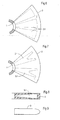
- Figur 1
- zeigt eine Vorrichtung mit Filterplatten gemäß der Erfindung in einer schematischen Aufrissansicht.
- Figur 2
- zeigt den Gegenstand von
Figur 1 in einer Draufsicht. - Figur 3
- zeigt eine abgewandelte Ausführungsform des Gegenstandes von
Figur 1 , wiederum in Draufsicht. - Figur 4
- zeigt ein Segment als Bestandteil einer Filtrationsplatte in Draufsicht.
- Figur 5
- zeigt eine Schnittansicht gemäß der Schnittlinie V - V von
Figur 4 in einer Abwicklung. - Die
Figuren 6 und 7 zeigen zwei weitere Ausführungsformen von Segmenten in Draufsicht. - Figur 8
- veranschaulicht in einem Axialschnitt eine Filtrationsplatte mit einer bestimmten Kanalkonfiguration.
- Figur 9
- zeigt eine Filtrationsplatte in Seitenansicht.
- Figur 10
- zeigt in einem zur Plattenebene senkrechten Schnitt - das heißt parallel zur Drehachse der Hohlwellen 1, 2, den Aufbau einer erfindungsgemäßen Filtrationsplatte.
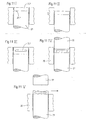
- Figur 11
- zeigt schematisch einen Teil einer Vorrichtung zum Durchführen des Verfahrens und veranschaulicht dessen einzelne Phasen.
- Figur 12
- zeigt schematisch eine erfindungsgemäße Vorrichtung mit zwei Kolben vor Beginn des Verdichtungsprozesses.
- Figur 13
- zeigt den Gegenstand von
Figur 12 am Ende des Verdichtungsprozesses. - Figur 14
- zeigt in vergrößerter Darstellung und schematisch den unteren Bereich der Vorrichtung gemäß der
Figuren 12 und 13 . - Figur 15
- zeigt eine alternative Ausführungsform zu
Figur 14 . - Wie man aus
Figur 1 erkennt, weist die Vorrichtung zwei Hohlwellen 1, 2 auf. Den beiden Hohlwellen ist jeweils ein Plattenpaket 3 beziehungsweise 4 zugeordnet. Die Filtrationsplatten sind parallel zueinander angeordnet. Die Filtrationsplatten 3 sind mit der Hohlwelle 1 drehfest verbunden, und die Filtrationsplatten 4 mit der Hohlwelle 2. - Die Filtrationsplatten 3, 4 bestehen aus porösem keramischen Material mit einer Keramikmembran, die die äußere Filtrationsplattenfläche bildet. Wie aus den
Figuren 4 und 5 erkennbar, sind sie mit Kanälen versehen. Da sich dieFiguren 4 und 5 auf ein Segment der Filtrationsplatten 3 beziehen, erkennt man dort die Kanäle 3.1. Die Kanäle sind radial angeordnet. Sie verlaufen somit vom Umfangsbereich des Segmentes zur Hohlwelle 3 und stehen mit deren Innenraum in leitender Verbindung. Gewisse Abweichungen von der radialen Richtung sind möglich. - Statt der dargestellten Ausführungsform ist auch die folgende Variante denkbar: Es sind zwei oder mehrere Pakete vorgesehen. Mindestens eines hiervon weist eine Hohlwelle auf und trägt aktive Filtrationsplatten. Es kann auch eine Anzahl von Paketen mit Dummyplatten bestückt sein, mit oder ohne Hohlwelle.
- Die betreffende Hohlwelle sowie die zugeordneten Filtrationsplatten werden hier als "Paket" bezeichnet. Dabei ist das aus Hohlwelle 1 und Filtrationsplatte 3 gebildete Paket genau gleich gestaltet und gleichartig aufgebaut, wie das aus Hohlwelle 2 und den Filtrationsplatten 4 aufgebaute Paket. Es wären jedoch auch Abweichungen hiervon möglich. So könnten beispielsweise die Filtrationsplatten des einen Paketes einen größeren Durchmesser als die Filtrationsplatten des anderen Paketes haben. Im vorliegenden Falle sind die Filtrationsplatten kreisförmig. Auch hier wären Abweichungen möglich. Beispielsweise käme eine ovale Form in Betracht.
- Die beiden Pakete sind in einem Behälter 5 angeordnet. Der Behälter 5 weist einen Einlass 5.1 sowie einen Auslass 5.2 auf. Die beiden Hohlwellen 1, 2 weisen an ihren oberen Enden Auslässe 1.1 beziehungsweise 1.2 auf.
- Die Vorrichtung arbeitet wie folgt:
Dem Behälter wird durch Einlass 5.1 das zu behandelnde Medium zugeführt. Das Filtrat/Permeat gelangt durch die Poren des keramischen Materiales der Keramikscheiben in die Kanäle 3.1 beziehungsweise 4.1- die letztgenannten hier nicht dargestellt. Das Permeat gelangt von den Kanälen in den Innenraum der beiden Hohlwellen 1, 2 und wird an den Auslässen 1.1, 1.2 abgeführt. - Was nicht durch die Poren des Keramikmaterials hindurchzudringen vermag, gelangt als Retentat zum Auslass 5.2 des Behälters 5.
- Aus der Darstellung gemäß
Figur 2 erkennt man, dass die Filtrationsplatten 3 des einen Paketes mit den Filtrationsplatten 4 des anderen Paketes überlappen. Im Überlappungsbereich 6 entsteht eine Turbulenz im Medium. Diese hat eine Reinigungswirkung an der Oberfläche der Filtrationsplatten zur Folge. Die spezifische Permeationsleistung wird groß, und der spezifische Energiebedarf wird klein. - Bei der in
Figur 3 gezeigten Ausführungsform sind drei Pakete vorgesehen. Diese sind wiederum in einem Behälter angeordnet - hier nicht dargestellt - - Eine weitere Möglichkeit besteht darin, eine noch größere Anzahl von Paketen innerhalb ein- und derselben Vorrichtung vorzusehen. So kann beispielsweise ein Paket zentral angeordnet werden, während die übrigen Pakete konzentrisch um das zentrale Paket herumgruppiert werden.
- Aus den
Figuren 4 und 5 erkennt man, dass die einzelne Filtrationsplatte 3, 4 aus einer Mehrzahl von Segmenten aufgebaut sein kann. Das hier dargestellte Kreissegment ist somit Bestandteil einer Filtrationsplatte 3. Die Filtrationsplatten können jedoch auch ganz und gar aus einem einzigen Teil aufgebaut sein. - Die in den
Figuren 5 und6 dargestellten Filtrationsplatten 3 weisen Permeat-Kanäle 3.1 bestimmter Konfigurationen auf. Wie man sieht, verjüngen sich die Kanäle in dieser Draufsicht gesehen von außen nach innen. Sie sind somit keilförmig. Im allgemeinen werden sich die Permeat-Kanäle parallel oder annähernd parallel oder annähernd parallel zu den Seitenflächen der Filtrationsplatte 3, 4 erstrecken. Im allgemeinen reichen sie bis zum Zentrum der betreffenden Filtrationsplatte, die dort eine Bohrung hat, und enden im Umfangsbereich vor dem äußeren Rand der Filtrationsplatte 3, 4. - Bei der Ausführungsform gemäß
Figur 7 sind die Kanäle 3.1 wiederum keilförmig, haben jedoch im radial äußeren Bereich jeweils eine Einbuchtung. Der Kanal hat somit in dieser Draufsicht eine Art Astgabelform. - Der Sinn dieser Kanalgestaltung besteht darin, dass das Permeat hierdurch kurze Wege zum Permeat-Ableitkanal zurückzulegen hat.
- Ein anderer Effekt wird erzielt durch die in
Figur 8 gezeigte Kanalgestaltung - diesmal in einem Axialschnitt durch das Plattenpaket gesehen. Wie man sieht, verjüngt sich der Kanal hier wiederum von außen nach innen. Der Sinn besteht in Folgendem: Bei einer rotierenden Filtrationsplatte steht das Permeat im Außenbereich der Filtrationsplatte unter leicht erhöhtem Druck. Die geschilderte Gestaltung des Kanales kompensiert diesen erhöhten Druck durch die Wandstärkenabnahme. Die Kanäle können schließlich derart gestaltet sein, dass die Fließgeschwindigkeit des Filtrats/Permeats auf dessen Weg zur Hohlwelle hin konstant ist. - Aus
Figur 9 erkennt man, dass die Filtrationsplatte 3 in ihrem Umfangsbereich stromlinienförmig gestaltet ist, etwa nach Art der angeströmten Kante eines Tragflügels. Es hat sich gezeigt, dass der Verschleiß der Membran hierdurch erheblich minimiert ist. - Die in
Figur 10 dargestellte Filtrationsplatte 3 ist wie folgt aufgebaut: sie umfasst zwei Stützkörperhälften 3.2, 3.3. Diese sind entlang einer Ebene 3.4 zusammengefügt. - Zwischen den beiden Stützkörperhälften 3.2, 3.3 befinden sich die bereits genannten Permeat-Kanäle 3.1, die das Permeat zu dem Innenraum der betreffenden Hohlwelle leiten.
- Die beiden Stützkörperhälften 3.2, 3.3 sind auf ihren Außenseiten wenigstens teilweise mit einer Membranfilterschicht 3.5 beschichtet.
- Die Ebene 3.4 ist von fundamentaler Bedeutung für die Funktion der Filtrationsplatte. Es wird nämlich angestrebt, dass die beiden Stützkörperhälften 3.2, 3.3 in der Ebene 3.4 eine innige Verbindung miteinander eingehen, und dass in dieser Ebene keinerlei Risse, Spalten oder Lufteinschlüsse vorliegen.
-
Figur 11 zeigt einen wesentlichen Teil einer Vorrichtung zum Durchführen des Verfahrens. Man erkennt einen Kolben 21 mit einer Stirnfläche 21.1. Man erkennt ferner eine Zylinderbüchse 20, in der der Kolben 21 geführt ist. - Zum Durchführen des Verfahrens wird in einer ersten Phase l sinterfähiges, pulverförmiges Material auf die Stirnfläche 21.1 des Kolbens 21 aufgebracht, so dass sich eine Schüttung 3.2 ergibt, die später eine der beiden Stützkörperhälften darstellt.
- In Phase II ist der Kolben 21 um eine bestimmte Wegstrecke nach unten gefahren. Genau wie bei der Darstellung gemäß der
Figuren 12 - 14 wird auch hier nach Aufbringen der ersten Schüttung 3.2 ein Zwischenkörper aufgebracht, bestehend aus einem Material, das sich unter bestimmten Bedingungen verflüchtigen kann, ferner eine zweite Schüttung, die die zweite Stützkörperhälfte darstellt. Dieser Zustand ist in Phase lll gezeigt. Man erkennt dort den immer noch abgefahrenen Kolben 21, der aber nun die erste Schüttung, den Zwischenkörper sowie die zweite Schüttung trägt. Die beiden Schüttungen gehen dabei ineinander über, so dass keinerlei Trennfuge besteht. Aus den beiden Schüttungen ist nunmehr ein einziges Formteil geworden, das den Zwischenkörper 3.7 umschließt. - Phase IV zeigt den Kolben 21, der sich nach wie vor in der Position von Phase III befindet, ferner das genannte Formteil mit Zwischenkörper. Man erkennt weiterhin einen zweiten Kolben 22, der von oben her auf das Formteil herabgesenkt ist. Das Formteil wird nunmehr zwischen den beiden Kolben 21, 22 verpresst, wobei mindestens einer der beiden Kolben relativ zum anderen verfahren wird. Wird Kolben 22 verfahren, so läuft er in derselben Zylinderhülse 20, wie Kolben 21, Wie man sieht, ist der zwischen den beiden Kolben 21, 22 befindliche Pressling gegenüber dem Zustand gemäß Phase III komprimiert, desgleichen der Zwischenkörper 3.7.
- Gleichzeitig mit dem Aufbringen von Druck kann auch Wärme auf das Formteil aufgebracht werden. Der Zwischenkörper besteht aus einem unter Druck und/oder Wärme sich verflüchtigenden Material.
- In Phase V sind die beiden Kolben 21, 22 nach oben hochgefahren. Kolben 22 ist dabei derart abgehoben, dass er das Formteil nicht mehr berührt. Das Formteil befindet sich jetzt mit seiner Unterkante auf der Höhe der Oberkante der Zylinderhülse 20. Es kann in Richtung des Pfeiles verschoben und damit von Kolben 21 abgenommen werden.
- Auf die Phase V folgt ein Sinterprozess. Dabei wird das Formteil hohen Temperaturen unterworfen. Dabei entsteht der nunmehr feste Stützkörper. Der Zwischenkörper 3.7 besteht aus einem Material, das bei Einwirkung entsprechender Temperaturen und/oder Chemikalien entweder sich verflüchtigt oder aufgelöst wird, so dass entsprechende Freiräume im Stützkörper verbleiben, um bei dem fertigen plattenförmigen Filtrationskörper als Kanäle zu dienen.
- Das Zwischenkörpermaterial kann aus komprimierbarem oder nicht - komprimierbarem Material bestehen.
- In den
Figuren 12 und 13 ist ebenfalls eine Vorrichtung dargestellt und der Verdichtungsvorgang veranschaulicht. Dabei arbeiten zwei Kolben 21, 22 gegeneinander. Die Arbeitsweise ist grundsätzlich die gleiche, wie in denFiguren 11 l ― 11 V gezeigt. Es ist somit auch hier ein Zwischenkörper vorhanden, der aber nicht dargestellt ist. Der Zwischenkörper besteht wiederum aus einem Material, das sich bei Einwirkung entsprechender Temperaturen oder Chemikalien verflüchtigt oder aufgelöst wird, so dass entsprechende Freiräume im fertigen, plattenförmigen Filtrationskörper verbleiben. -
Figur 12 veranschaulicht die Vorrichtung im Ausgangsstadium. Dabei befindet sich im Formnest ein entsprechendes Pulver, das aus sinterfähigem, kornförmigem Material besteht. -
Figur 13 zeigt den verdichteten Zustand des Pulvers. - Im Ausgangszustand gemäß
Figur 12 beträgt der Luftanteil beispielsweise 75 Vol.-%. Die von Kolben 21 aufgebrachte Presskraft beträgt noch 0 kp/cm2.
Demgemäss steht der Inhalt des Formnestes, das heißt Pulver und Luft, unter Atmosphärendruck. Bei der Verdichtung wird das zwischen den Pulverpartikeln eingeschlossene Luftvolumen auf ein fünftel verringert. - Im verdichteten Zustand gemäß
Figur 13 beträgt der Luftanteil 37,5 Vol.-%. Die Presskraft, die von Kolben 21 ausgeübt wird, beträgt 1000 kp/cm2. Die zwischen den Pulverpartikeln eingeschlossene Luft steht unter einen Druck von 5 atm. - Der Druck ergibt sich aus dem Anfangsdruck vor Beginn des Verdichtungsprozesses, und dem Verdichtungsfaktor.
- Ist der Luftdruck im Pressling nach der Entlastung (Presskraft = 0) größer, als der äußere Luftdruck, so steht der Pressling unter einem Innendruck. Es können sich Risse bilden, die den Pressling zerstören oder zumindest funktionsuntüchtig machen.
- Gemäß der Erfindung wird diese Zerstörung vermieden durch die erfindungsgemäßen Maßnahmen.
- Diese Maßnahmen können in Folgendem bestehen:
Es wird Luft während des Verdichtungsvorganges abgeführt. Dies kann beispielsweise dadurch geschehen, dass einer der beiden Pressstempel, beispielsweise Pressstempel 21, mit Bohrungen 21.1 versehen wird. - Auch kann die Zylinderhülse 20 mit Bohrungen 20.1 versehen sein.
- Schließlich können sowohl Kolben 21 oder Kolben 22 und zugleich die Zylinderhülse 20 mit Bohrungen versehen sein.
- Alternativ zu Bohrungen kann das Material derjenigen Teile, die das Formnest bilden, somit der Zylinderhülse 20 und/oder der Kolben 21, 22, porös sein. Dabei muss es sich um sogenanntes offenporiges Material handeln, bei welchem die Poren in leitender Verbindung miteinander stehen, so dass die im Formnest befindliche Luft während des Verdichtungsvorganges abgeführt werden kann. Dabei kann es sich beispielsweise um Sintermetall handeln.
- Eine interessante Variante ist in
Figur 15 gezeigt. Dort besteht der Kolben 21 aus einer oberen, relativ dünnen Lage 21.2 sowie aus einem unteren Teil 21.3. Der untere Teil 21.3 weist ein verzweigtes Netz von Bohrungen 21.1 relativ großer lichter Weite auf. Die Lage 21.2 ist wiederum aus offenporigem Material gebildet. - Diese Ausführungsform hat den folgenden Vorteil:
Da die Lage 21.2 relativ dünn ist, ist der Weg der aus dem Formnest beim Verdichtungsprozess verdrängten Luft sehr klein, jedenfalls bis zum Erreichen der Bohrungen oder Kanäle 21.1. Der kleine Weg bedeutet aber einen geringen Strömungswiderstand, so dass relativ viel Luft in kurzer Zeit aus dem Formnest entweichen kann. Dieser Vorgang kann begünstigt werden durch Anschließen eines Vakuums - siehe Vakuumanschluss 21.4 - im unteren Bereich des Kolbens 21. - Eine weitere Möglichkeit des Vermeidens von Lufteinschlüssen besteht darin, den Verdichtungsvorgang entsprechend langsam ablaufen zu lassen. Je nach Art des Sitzes der Kolben 21, 22 in der Zylinderhülse 20 wird nämlich mehr oder minder viel Luft durch den Ringspalt zwischen Kolben und Zylinderhülse entweichen. Entgegen dem allgemeinen Bestreben, einen Produktionsprozess möglichst schnell ablaufen zu lassen, wird man somit den Verdichtungsprozess verzögert ablaufen lassen. Als Faustformel kann Folgendes gelten:
Die Verringerung des Volumens des Formnestes beim Verdichtungsprozess sollte wenigstens annähernd gleich sein mit dem Volumen der beim Verdichtungsprozess entweichenden Luft. - Auch kann es zweckmäßig sein, den Verdichtungsprozess intermittierend ablaufen zu lassen. Dies bedeutet, dass man während einer ersten Phase einen gewissen Pressdruck aufbringt, bis ein bestimmter Kompressionszustand A erreicht ist. Sodann wird eine kurze Pause eingelegt. Es folgt ein weiterer Verdichtungsvorgang bis zum Erreichen eines zweiten Kompressionszustandes B, und so weiter.
- Eine weitere Möglichkeit des Vermeidens der Nachteile eingeschlossener Luft im Formnest besteht in Folgendem:
Wie bei der Beschreibung vonFigur 11 erwähnt, werden zwei Pulverquanten in das Formnest eingebracht. - Das Vorverdichten eines ersten Quantums könnte stufenweise geschehen. Während einer ersten Verdichtungsstufe wird der größte Teil des ersten Quantums stark vorverdichtet, und sodann wird ein zweiter, kleiner Teil des ersten Quantums auf den ersten, stark verdichteten Teil aufgebracht, und nochmals unter mäßigem Druck verdichtet. Diese Vorgehensweise hat den Vorteil, dass der zweite, mäßig vorverdichtete Teil des ersten Quantums eine innige Bindung mit dem zweiten Quantum eingehen kann, da die Körner des zweiten, weniger verdichteten Teiles noch eine größere Bewegungsfreiheit haben.
- Eine weitere Möglichkeit der Lösung der gestellten Aufgabe besteht darin, auf das Formnest oder ganz allgemein in den Bereich zwischen den beiden Kolben 21, 22 einen Unterdruck aufzubringen. Ein solches Evakuieren kann bereits vor dem verdichten eingeleitet werden. Es kann auch während des Verdichtens stattfinden. Es kann auch vor dem verdichten und während des Verdichtens stattfinden.
- Dabei können das Evakuieren einerseits und das Verdichten andererseits aufeinander abgestimmt werden, so dass im Formnest während des gesamten Prozesses ein gewünschter Druck herrscht. Die beiden genannten Vorgänge können beispielsweise derart ablaufen, dass in sie sich gegenseitig aufheben, so dass im Formnest zu jeden Zeitpunkt während des Verdichtens Atmosphärendruck herrscht. Statt dessen könnte auch ein gewisser Überdruck zugelassen werden, oder sogar ein gewisser Unterdruck.
Claims (6)
- Verfahren zum Herstellen eines plattenförmigen Filtrationskörpers (4) aus einem sinterfähigen Pulver, wobei der Filtrationskörper (4) einen Stützkörper (3) umfasst, der aus porösem Material besteht, und in den Permeat-Ableitkanäle (3.1) eingebettet sind; wenigstens eine filtrierende Schicht (3.5), die auf den Außenseiten des Stützkörpers (3) aufgebracht ist, mit den folgenden Verfahrensschrltten:1.1 es wird ein erstes Quantum sinterfähigen Pulvers in ein Formnest eingebracht, dessen Innenkontur annähernd der Außenkontur des Stützkörpers (3) entspricht;1.2 es wird auf das erste Quantum ein Zwischenkörper (3.7) aufgebracht, der aus einem unter Druck und/oder Wärme sich verflüchtigenden Material besteht;1.3 es wird ein zweites Quantum sinterfähigen Pulvers auf den Zwischenkörper (3.7) aufgeschüttet;1.4 die beiden Quanten mit dem dazwischen befindlichen Zwischenkörper (3.7) werden durch Verdichten zu einem Zwischenprodukt geformt;1.5 das Zwischenprodukt wird gesintert, gegebenenfalls durch mechanische Bearbeitung in die endgültige Form gebracht und mit einer filtrierenden Schicht überzogen; gekennzeichnet durch die folgenden Merkmale:1.6 vor dem Verdichten und/oder während des Verdichtens wird an das Formnest ein Unterdruck angelegt, oder es wird das Verdichten intermittierend durchgeführt.
- Verfahren nach Anspruch 1, dadurch gekennzeichnet, dass die Geschwindigkeit des Pressens oder die Haltedauer des gepressten Zustandes derart bemessen wird, dass die zwischen den Pulverpartikeln eingeschlossene Luft in einem solchen Maße entweicht, dass der Druck in der darin verbleibenden Luft annähernd auf Umgebungsdruck absinkt.
- Verfahren nach Anspruch 1 oder 2, dadurch gekennzeichnet, dass wenigstens eines der Quanten außerhalb des Formnestes vorverdichtet oder völlig verdichtet wird.
- Vorrichtung zum Herstellen eines plattenförmigen Filtrationskörpers (4), wobei der Filtrationskörper (4) einen Stützkörper (3) umfasst, der aus porösem Material besteht und in den Permeat-Ableitkanäle (3.1) eingebettet sind;4.1 mit einem Formnest, dessen Innenkontur der Außenkontur des Stützkörpers (3) entspricht;4.2 mit einer Presseinrichtung zum Verdichten eines in das Formnest einzubringenden Pulvers; gekennzeichnet durch die folgenden Merkmale:4.3 mit Kanälen (20.1, 21.1) zum Ableiten von im Formnest enthaltener Luft;4.4 mit einer Einrichtung zum Anlegen eines Unterdruckes an die Kanäle (20.1, 21.1).
- Vorrichtung nach Anspruch 4, dadurch gekennzeichnet, dass wenigstens Bereiche der das Formnest bildenden Bauteile (20, 21, 22) aus porösem Material bestehen.
- Vorrichtung nach Anspruch 5, dadurch gekennzeichnet, dass den Kanälen (20.1, 21.1) oder den Poren des porösen Materials eine Unterdruckeinrichtung zum Extrahieren von im Formnest befindlicher Luft zugeordnet ist.
Applications Claiming Priority (2)
| Application Number | Priority Date | Filing Date | Title |
|---|---|---|---|
| DE10228432A DE10228432A1 (de) | 2002-06-26 | 2002-06-26 | Plattenförmiger Filtrationskörper |
| DE10228432 | 2002-06-26 |
Publications (2)
| Publication Number | Publication Date |
|---|---|
| EP1374967A1 EP1374967A1 (de) | 2004-01-02 |
| EP1374967B1 true EP1374967B1 (de) | 2012-05-30 |
Family
ID=29716651
Family Applications (1)
| Application Number | Title | Priority Date | Filing Date |
|---|---|---|---|
| EP03012592A Expired - Lifetime EP1374967B1 (de) | 2002-06-26 | 2003-06-03 | Plattenförmiger Filtrationskörper |
Country Status (4)
| Country | Link |
|---|---|
| EP (1) | EP1374967B1 (de) |
| DE (1) | DE10228432A1 (de) |
| DK (1) | DK1374967T3 (de) |
| ES (1) | ES2386423T3 (de) |
Families Citing this family (3)
| Publication number | Priority date | Publication date | Assignee | Title |
|---|---|---|---|---|
| WO2002005935A2 (de) * | 2000-07-13 | 2002-01-24 | Aaflowsystems Gmbh & Co. Kg | Rotationsfilter |
| DE102010019871B4 (de) * | 2010-05-07 | 2018-07-12 | A. Kayser Automotive Systems Gmbh | Filtrationsvorrichtung |
| DE202015105788U1 (de) * | 2015-10-30 | 2017-02-01 | Gea Mechanical Equipment Gmbh | Montagevorrichtung für eine Filtrieranordnung |
Family Cites Families (4)
| Publication number | Priority date | Publication date | Assignee | Title |
|---|---|---|---|---|
| ATE53179T1 (de) * | 1985-11-30 | 1990-06-15 | Akio Nakano | Form fuer hochschmelzende metalle und verfahren zur herstellung hochschmelzender metallgegenstaende. |
| DE10039272C1 (de) * | 2000-08-11 | 2002-01-24 | Aaflowsystems Gmbh & Co Kg | Plattenförmiger Filtrationskörper |
| DE10023292C1 (de) * | 2000-05-12 | 2001-08-30 | Aaflowsystems Gmbh & Co Kg | Plattenförmiger Filtrationskörper |
| WO2002005935A2 (de) * | 2000-07-13 | 2002-01-24 | Aaflowsystems Gmbh & Co. Kg | Rotationsfilter |
-
2002
- 2002-06-26 DE DE10228432A patent/DE10228432A1/de not_active Withdrawn
-
2003
- 2003-06-03 ES ES03012592T patent/ES2386423T3/es not_active Expired - Lifetime
- 2003-06-03 EP EP03012592A patent/EP1374967B1/de not_active Expired - Lifetime
- 2003-06-03 DK DK03012592.6T patent/DK1374967T3/da active
Also Published As
| Publication number | Publication date |
|---|---|
| ES2386423T3 (es) | 2012-08-20 |
| DE10228432A1 (de) | 2004-02-12 |
| EP1374967A1 (de) | 2004-01-02 |
| DK1374967T3 (da) | 2012-07-02 |
Similar Documents
| Publication | Publication Date | Title |
|---|---|---|
| EP2496403B1 (de) | Vorrichtung und verfahren zur herstellung eines dreidimensionalen körpers | |
| EP1597003B1 (de) | Verfahren zur herstellung von miniaturkörpern oder mikrostrukturierten körpern | |
| EP2448697B1 (de) | Gussform mit entlüfter | |
| DE102014007869B4 (de) | Vorrichtung und Verfahren zum Infiltrieren von Fasermaterial mit Harz zur Herstellung eines Faserverbundbauteils | |
| DE3144678A1 (de) | Verfahren und einrichtung zur herstellung von formlingen aus einer rieselfaehigen masse | |
| DE3917277A1 (de) | Verfahren und vorrichtung zur herstellung von fertigteilen als verbundkoerper aus pulverfoermigen werkstoffen | |
| EP2121222A2 (de) | Keramischer und/oder pulvermetallurgischer verbundformkörper und verfahren zu seiner herstellung | |
| EP1916091A1 (de) | Verfahren zur herstellung von faserverbundbauteilen | |
| EP3300792A2 (de) | Verfahren zur herstellung einer keramischen filtrationsscheibe | |
| DE1289742B (de) | Verfahren zur Entnahme vorgepresster Probetabletten | |
| EP3363527B1 (de) | Verfahren zum betrieb einer filtrationsanlage | |
| DE7602966U1 (de) | Giesserei-formmaschine fuer kastenformen | |
| DE3517463C1 (de) | Isostatische Pressform zur Herstellung von Formlingen aus keramischer Masse | |
| EP1412064B1 (de) | Verfahren zum herstellen eines plattenförmigen filtrationskörpers | |
| EP3173202B1 (de) | Spezial-keramikbauteile | |
| DE10023292C1 (de) | Plattenförmiger Filtrationskörper | |
| EP0521179A1 (de) | Verfahren und Vorrichtung zur Herstellung von rohrförmigen Filterelementen | |
| EP1374967A1 (de) | Plattenförmiger Filtrationskörper | |
| DE10039272C1 (de) | Plattenförmiger Filtrationskörper | |
| EP2809461B1 (de) | Vorrichtung und verfahren zur herstellung von porenfreien profilen aus trennresten mittels strangpressen | |
| AT515747B1 (de) | Verfahren zur Herstellung einer Baugruppe | |
| DE2262400B2 (de) | Verfahren zum Herstellen von mehrschichtigen Formkörpern mit vollem oder hohlem Querschnitt | |
| DE102019127666A1 (de) | Lochplatte zum Granulieren von Schmelzen sowie Verfahren zu deren Herstellung | |
| EP1488840B1 (de) | Verfahren zur Herstellung eines Verbundfiltermaterials | |
| WO2018069513A1 (de) | Vorrichtung zur herstellung von keramikteilen |
Legal Events
| Date | Code | Title | Description |
|---|---|---|---|
| PUAI | Public reference made under article 153(3) epc to a published international application that has entered the european phase |
Free format text: ORIGINAL CODE: 0009012 |
|
| AK | Designated contracting states |
Kind code of ref document: A1 Designated state(s): AT BE BG CH CY CZ DE DK EE ES FI FR GB GR HU IE IT LI LU MC NL PT RO SE SI SK TR |
|
| AX | Request for extension of the european patent |
Extension state: AL LT LV MK |
|
| 17P | Request for examination filed |
Effective date: 20040702 |
|
| AKX | Designation fees paid |
Designated state(s): AT BE BG CH CY CZ DE DK EE ES FI FR GB GR HU IE IT LI LU MC NL PT RO SE SI SK TR |
|
| RAP1 | Party data changed (applicant data changed or rights of an application transferred) |
Owner name: WESTFALIA SEPARATOR AG |
|
| 17Q | First examination report despatched |
Effective date: 20071227 |
|
| R17C | First examination report despatched (corrected) |
Effective date: 20080110 |
|
| REG | Reference to a national code |
Ref country code: DE Ref legal event code: R079 Ref document number: 50314346 Country of ref document: DE Free format text: PREVIOUS MAIN CLASS: B01D0033210000 Ipc: B01D0071020000 |
|
| GRAP | Despatch of communication of intention to grant a patent |
Free format text: ORIGINAL CODE: EPIDOSNIGR1 |
|
| RIC1 | Information provided on ipc code assigned before grant |
Ipc: B01D 63/16 20060101ALI20111116BHEP Ipc: B01D 71/02 20060101AFI20111116BHEP |
|
| GRAS | Grant fee paid |
Free format text: ORIGINAL CODE: EPIDOSNIGR3 |
|
| GRAA | (expected) grant |
Free format text: ORIGINAL CODE: 0009210 |
|
| AK | Designated contracting states |
Kind code of ref document: B1 Designated state(s): AT BE BG CH CY CZ DE DK EE ES FI FR GB GR HU IE IT LI LU MC NL PT RO SE SI SK TR |
|
| REG | Reference to a national code |
Ref country code: GB Ref legal event code: FG4D Free format text: NOT ENGLISH |
|
| REG | Reference to a national code |
Ref country code: CH Ref legal event code: EP |
|
| REG | Reference to a national code |
Ref country code: AT Ref legal event code: REF Ref document number: 559778 Country of ref document: AT Kind code of ref document: T Effective date: 20120615 |
|
| REG | Reference to a national code |
Ref country code: IE Ref legal event code: FG4D Free format text: LANGUAGE OF EP DOCUMENT: GERMAN |
|
| REG | Reference to a national code |
Ref country code: CH Ref legal event code: NV Representative=s name: SCHMAUDER & PARTNER AG PATENT- UND MARKENANWAELTE |
|
| REG | Reference to a national code |
Ref country code: DK Ref legal event code: T3 |
|
| REG | Reference to a national code |
Ref country code: NL Ref legal event code: T3 |
|
| REG | Reference to a national code |
Ref country code: SE Ref legal event code: TRGR |
|
| REG | Reference to a national code |
Ref country code: DE Ref legal event code: R096 Ref document number: 50314346 Country of ref document: DE Effective date: 20120726 |
|
| REG | Reference to a national code |
Ref country code: ES Ref legal event code: FG2A Ref document number: 2386423 Country of ref document: ES Kind code of ref document: T3 Effective date: 20120820 |
|
| PG25 | Lapsed in a contracting state [announced via postgrant information from national office to epo] |
Ref country code: CY Free format text: LAPSE BECAUSE OF FAILURE TO SUBMIT A TRANSLATION OF THE DESCRIPTION OR TO PAY THE FEE WITHIN THE PRESCRIBED TIME-LIMIT Effective date: 20120530 Ref country code: FI Free format text: LAPSE BECAUSE OF FAILURE TO SUBMIT A TRANSLATION OF THE DESCRIPTION OR TO PAY THE FEE WITHIN THE PRESCRIBED TIME-LIMIT Effective date: 20120530 |
|
| PG25 | Lapsed in a contracting state [announced via postgrant information from national office to epo] |
Ref country code: SI Free format text: LAPSE BECAUSE OF FAILURE TO SUBMIT A TRANSLATION OF THE DESCRIPTION OR TO PAY THE FEE WITHIN THE PRESCRIBED TIME-LIMIT Effective date: 20120530 Ref country code: GR Free format text: LAPSE BECAUSE OF FAILURE TO SUBMIT A TRANSLATION OF THE DESCRIPTION OR TO PAY THE FEE WITHIN THE PRESCRIBED TIME-LIMIT Effective date: 20120831 |
|
| BERE | Be: lapsed |
Owner name: WESTFALIA SEPARATOR A.G. Effective date: 20120630 |
|
| PG25 | Lapsed in a contracting state [announced via postgrant information from national office to epo] |
Ref country code: SK Free format text: LAPSE BECAUSE OF FAILURE TO SUBMIT A TRANSLATION OF THE DESCRIPTION OR TO PAY THE FEE WITHIN THE PRESCRIBED TIME-LIMIT Effective date: 20120530 Ref country code: RO Free format text: LAPSE BECAUSE OF FAILURE TO SUBMIT A TRANSLATION OF THE DESCRIPTION OR TO PAY THE FEE WITHIN THE PRESCRIBED TIME-LIMIT Effective date: 20120530 Ref country code: EE Free format text: LAPSE BECAUSE OF FAILURE TO SUBMIT A TRANSLATION OF THE DESCRIPTION OR TO PAY THE FEE WITHIN THE PRESCRIBED TIME-LIMIT Effective date: 20120530 Ref country code: CZ Free format text: LAPSE BECAUSE OF FAILURE TO SUBMIT A TRANSLATION OF THE DESCRIPTION OR TO PAY THE FEE WITHIN THE PRESCRIBED TIME-LIMIT Effective date: 20120530 Ref country code: MC Free format text: LAPSE BECAUSE OF NON-PAYMENT OF DUE FEES Effective date: 20120630 |
|
| PG25 | Lapsed in a contracting state [announced via postgrant information from national office to epo] |
Ref country code: PT Free format text: LAPSE BECAUSE OF FAILURE TO SUBMIT A TRANSLATION OF THE DESCRIPTION OR TO PAY THE FEE WITHIN THE PRESCRIBED TIME-LIMIT Effective date: 20121001 |
|
| REG | Reference to a national code |
Ref country code: IE Ref legal event code: MM4A |
|
| PLBE | No opposition filed within time limit |
Free format text: ORIGINAL CODE: 0009261 |
|
| STAA | Information on the status of an ep patent application or granted ep patent |
Free format text: STATUS: NO OPPOSITION FILED WITHIN TIME LIMIT |
|
| PG25 | Lapsed in a contracting state [announced via postgrant information from national office to epo] |
Ref country code: BE Free format text: LAPSE BECAUSE OF NON-PAYMENT OF DUE FEES Effective date: 20120630 Ref country code: IE Free format text: LAPSE BECAUSE OF NON-PAYMENT OF DUE FEES Effective date: 20120603 |
|
| 26N | No opposition filed |
Effective date: 20130301 |
|
| REG | Reference to a national code |
Ref country code: DE Ref legal event code: R097 Ref document number: 50314346 Country of ref document: DE Effective date: 20130301 |
|
| PG25 | Lapsed in a contracting state [announced via postgrant information from national office to epo] |
Ref country code: BG Free format text: LAPSE BECAUSE OF FAILURE TO SUBMIT A TRANSLATION OF THE DESCRIPTION OR TO PAY THE FEE WITHIN THE PRESCRIBED TIME-LIMIT Effective date: 20120830 |
|
| REG | Reference to a national code |
Ref country code: AT Ref legal event code: MM01 Ref document number: 559778 Country of ref document: AT Kind code of ref document: T Effective date: 20120603 |
|
| PG25 | Lapsed in a contracting state [announced via postgrant information from national office to epo] |
Ref country code: AT Free format text: LAPSE BECAUSE OF NON-PAYMENT OF DUE FEES Effective date: 20120603 |
|
| PG25 | Lapsed in a contracting state [announced via postgrant information from national office to epo] |
Ref country code: LU Free format text: LAPSE BECAUSE OF NON-PAYMENT OF DUE FEES Effective date: 20120603 |
|
| PG25 | Lapsed in a contracting state [announced via postgrant information from national office to epo] |
Ref country code: HU Free format text: LAPSE BECAUSE OF FAILURE TO SUBMIT A TRANSLATION OF THE DESCRIPTION OR TO PAY THE FEE WITHIN THE PRESCRIBED TIME-LIMIT Effective date: 20030603 |
|
| REG | Reference to a national code |
Ref country code: FR Ref legal event code: PLFP Year of fee payment: 14 |
|
| REG | Reference to a national code |
Ref country code: FR Ref legal event code: PLFP Year of fee payment: 15 |
|
| REG | Reference to a national code |
Ref country code: FR Ref legal event code: PLFP Year of fee payment: 16 |
|
| PGFP | Annual fee paid to national office [announced via postgrant information from national office to epo] |
Ref country code: SE Payment date: 20190418 Year of fee payment: 17 Ref country code: TR Payment date: 20190530 Year of fee payment: 17 |
|
| PGFP | Annual fee paid to national office [announced via postgrant information from national office to epo] |
Ref country code: CH Payment date: 20190627 Year of fee payment: 17 |
|
| PGFP | Annual fee paid to national office [announced via postgrant information from national office to epo] |
Ref country code: ES Payment date: 20190712 Year of fee payment: 17 |
|
| REG | Reference to a national code |
Ref country code: CH Ref legal event code: PL |
|
| PG25 | Lapsed in a contracting state [announced via postgrant information from national office to epo] |
Ref country code: LI Free format text: LAPSE BECAUSE OF NON-PAYMENT OF DUE FEES Effective date: 20200630 Ref country code: CH Free format text: LAPSE BECAUSE OF NON-PAYMENT OF DUE FEES Effective date: 20200630 |
|
| PG25 | Lapsed in a contracting state [announced via postgrant information from national office to epo] |
Ref country code: SE Free format text: LAPSE BECAUSE OF NON-PAYMENT OF DUE FEES Effective date: 20200604 |
|
| PGFP | Annual fee paid to national office [announced via postgrant information from national office to epo] |
Ref country code: DE Payment date: 20210628 Year of fee payment: 19 Ref country code: FR Payment date: 20210630 Year of fee payment: 19 Ref country code: IT Payment date: 20210630 Year of fee payment: 19 Ref country code: NL Payment date: 20210623 Year of fee payment: 19 |
|
| PGFP | Annual fee paid to national office [announced via postgrant information from national office to epo] |
Ref country code: DK Payment date: 20210624 Year of fee payment: 19 Ref country code: GB Payment date: 20210624 Year of fee payment: 19 |
|
| REG | Reference to a national code |
Ref country code: SE Ref legal event code: EUG |
|
| REG | Reference to a national code |
Ref country code: ES Ref legal event code: FD2A Effective date: 20211026 |
|
| PG25 | Lapsed in a contracting state [announced via postgrant information from national office to epo] |
Ref country code: ES Free format text: LAPSE BECAUSE OF NON-PAYMENT OF DUE FEES Effective date: 20200604 |
|
| PG25 | Lapsed in a contracting state [announced via postgrant information from national office to epo] |
Ref country code: TR Free format text: LAPSE BECAUSE OF NON-PAYMENT OF DUE FEES Effective date: 20200603 |
|
| REG | Reference to a national code |
Ref country code: DE Ref legal event code: R119 Ref document number: 50314346 Country of ref document: DE |
|
| REG | Reference to a national code |
Ref country code: DK Ref legal event code: EBP Effective date: 20220630 |
|
| REG | Reference to a national code |
Ref country code: NL Ref legal event code: MM Effective date: 20220701 |
|
| GBPC | Gb: european patent ceased through non-payment of renewal fee |
Effective date: 20220603 |
|
| PG25 | Lapsed in a contracting state [announced via postgrant information from national office to epo] |
Ref country code: NL Free format text: LAPSE BECAUSE OF NON-PAYMENT OF DUE FEES Effective date: 20220701 |
|
| PG25 | Lapsed in a contracting state [announced via postgrant information from national office to epo] |
Ref country code: FR Free format text: LAPSE BECAUSE OF NON-PAYMENT OF DUE FEES Effective date: 20220630 |
|
| PG25 | Lapsed in a contracting state [announced via postgrant information from national office to epo] |
Ref country code: GB Free format text: LAPSE BECAUSE OF NON-PAYMENT OF DUE FEES Effective date: 20220603 Ref country code: DE Free format text: LAPSE BECAUSE OF NON-PAYMENT OF DUE FEES Effective date: 20230103 |
|
| PG25 | Lapsed in a contracting state [announced via postgrant information from national office to epo] |
Ref country code: IT Free format text: LAPSE BECAUSE OF NON-PAYMENT OF DUE FEES Effective date: 20220603 Ref country code: DK Free format text: LAPSE BECAUSE OF NON-PAYMENT OF DUE FEES Effective date: 20220630 |