EP1372838B1 - Process of conveying granular solids - Google Patents
Process of conveying granular solids Download PDFInfo
- Publication number
- EP1372838B1 EP1372838B1 EP02708353.4A EP02708353A EP1372838B1 EP 1372838 B1 EP1372838 B1 EP 1372838B1 EP 02708353 A EP02708353 A EP 02708353A EP 1372838 B1 EP1372838 B1 EP 1372838B1
- Authority
- EP
- European Patent Office
- Prior art keywords
- solids
- line
- pressure
- zone
- ascending
- Prior art date
- Legal status (The legal status is an assumption and is not a legal conclusion. Google has not performed a legal analysis and makes no representation as to the accuracy of the status listed.)
- Expired - Lifetime
Links
- 239000007787 solid Substances 0.000 title claims description 57
- 238000000034 method Methods 0.000 title claims description 15
- 230000001174 ascending effect Effects 0.000 claims description 20
- IJGRMHOSHXDMSA-UHFFFAOYSA-N Atomic nitrogen Chemical compound N#N IJGRMHOSHXDMSA-UHFFFAOYSA-N 0.000 description 10
- 239000007789 gas Substances 0.000 description 10
- 239000011261 inert gas Substances 0.000 description 9
- 239000012159 carrier gas Substances 0.000 description 7
- 239000003054 catalyst Substances 0.000 description 6
- 229910052757 nitrogen Inorganic materials 0.000 description 5
- XEEYBQQBJWHFJM-UHFFFAOYSA-N Iron Chemical compound [Fe] XEEYBQQBJWHFJM-UHFFFAOYSA-N 0.000 description 4
- 239000000463 material Substances 0.000 description 3
- 230000001105 regulatory effect Effects 0.000 description 3
- 239000011800 void material Substances 0.000 description 3
- 230000004888 barrier function Effects 0.000 description 2
- 239000013590 bulk material Substances 0.000 description 2
- 238000010586 diagram Methods 0.000 description 2
- 238000005243 fluidization Methods 0.000 description 2
- 238000012423 maintenance Methods 0.000 description 2
- 239000002245 particle Substances 0.000 description 2
- 238000000926 separation method Methods 0.000 description 2
- 239000004215 Carbon black (E152) Substances 0.000 description 1
- 239000003245 coal Substances 0.000 description 1
- 238000004939 coking Methods 0.000 description 1
- 238000005336 cracking Methods 0.000 description 1
- 238000007599 discharging Methods 0.000 description 1
- 210000002310 elbow joint Anatomy 0.000 description 1
- 239000012530 fluid Substances 0.000 description 1
- 229930195733 hydrocarbon Natural products 0.000 description 1
- 150000002430 hydrocarbons Chemical class 0.000 description 1
- 239000013618 particulate matter Substances 0.000 description 1
- 239000000376 reactant Substances 0.000 description 1
- 230000001172 regenerating effect Effects 0.000 description 1
- 230000008929 regeneration Effects 0.000 description 1
- 238000011069 regeneration method Methods 0.000 description 1
- 238000007789 sealing Methods 0.000 description 1
- 230000007704 transition Effects 0.000 description 1
Images

Classifications
-
- C—CHEMISTRY; METALLURGY
- C21—METALLURGY OF IRON
- C21B—MANUFACTURE OF IRON OR STEEL
- C21B13/00—Making spongy iron or liquid steel, by direct processes
- C21B13/0086—Conditioning, transformation of reduced iron ores
-
- B—PERFORMING OPERATIONS; TRANSPORTING
- B01—PHYSICAL OR CHEMICAL PROCESSES OR APPARATUS IN GENERAL
- B01J—CHEMICAL OR PHYSICAL PROCESSES, e.g. CATALYSIS OR COLLOID CHEMISTRY; THEIR RELEVANT APPARATUS
- B01J8/00—Chemical or physical processes in general, conducted in the presence of fluids and solid particles; Apparatus for such processes
- B01J8/0015—Feeding of the particles in the reactor; Evacuation of the particles out of the reactor
- B01J8/0025—Feeding of the particles in the reactor; Evacuation of the particles out of the reactor by an ascending fluid
-
- B—PERFORMING OPERATIONS; TRANSPORTING
- B65—CONVEYING; PACKING; STORING; HANDLING THIN OR FILAMENTARY MATERIAL
- B65G—TRANSPORT OR STORAGE DEVICES, e.g. CONVEYORS FOR LOADING OR TIPPING, SHOP CONVEYOR SYSTEMS OR PNEUMATIC TUBE CONVEYORS
- B65G53/00—Conveying materials in bulk through troughs, pipes or tubes by floating the materials or by flow of gas, liquid or foam
- B65G53/34—Details
- B65G53/52—Adaptations of pipes or tubes
- B65G53/521—Adaptations of pipes or tubes means for preventing the accumulation or for removal of deposits
-
- B—PERFORMING OPERATIONS; TRANSPORTING
- B01—PHYSICAL OR CHEMICAL PROCESSES OR APPARATUS IN GENERAL
- B01J—CHEMICAL OR PHYSICAL PROCESSES, e.g. CATALYSIS OR COLLOID CHEMISTRY; THEIR RELEVANT APPARATUS
- B01J2208/00—Processes carried out in the presence of solid particles; Reactors therefor
- B01J2208/00008—Controlling the process
- B01J2208/00539—Pressure
-
- Y—GENERAL TAGGING OF NEW TECHNOLOGICAL DEVELOPMENTS; GENERAL TAGGING OF CROSS-SECTIONAL TECHNOLOGIES SPANNING OVER SEVERAL SECTIONS OF THE IPC; TECHNICAL SUBJECTS COVERED BY FORMER USPC CROSS-REFERENCE ART COLLECTIONS [XRACs] AND DIGESTS
- Y02—TECHNOLOGIES OR APPLICATIONS FOR MITIGATION OR ADAPTATION AGAINST CLIMATE CHANGE
- Y02P—CLIMATE CHANGE MITIGATION TECHNOLOGIES IN THE PRODUCTION OR PROCESSING OF GOODS
- Y02P10/00—Technologies related to metal processing
- Y02P10/10—Reduction of greenhouse gas [GHG] emissions
- Y02P10/134—Reduction of greenhouse gas [GHG] emissions by avoiding CO2, e.g. using hydrogen
Definitions
- This invention relates to a process of continuously conveying granular solids according to the preamble of claim 1.
- the granular solids e.g. direct-reduced iron
- the granular solids are brought from an elevated pressure to ambient pressure for further processing in a plant.
- hot direct-reduced iron is conveyed from a fluidized-bed reactor to a pressurized cyclone, from where the granular solids are discharged downwards via a storage bin through a descending line.
- Inert gas is introduced into the descending line.
- the descending line is usually connected with an ascending line through which the granular solids are conveyed upwards into an impact pot by supplying inert gas into the ascending line. From said impact pot, the solids are introduced into a briquetting bin while further introducing inert gas. Due to the continuous supply of fine-grained solids, a column of these solids is formed in the descending line, which column at the same time represents a pressure barrier.
- fine-grained solids are introduced into an inflow tank, the amount supplied again being regulated by means of a valve.
- a supply of fine-grained solids is formed, into which extends a tube through which the solids are transported into a tank disposed at a higher level.
- a line pressurizing the inflow tank opens into the inflow tank, whereby the solids are transported through the tube into the tank disposed at a higher level.
- This known process likewise uses valves for regulating the inflow of solids.
- the inflow tank For larger amounts of solids to be transported, the inflow tank must be dimensioned correspondingly large, which again makes this apparatus very complex and expensive.
- US 2,978,279 upon which the preamble of claim 1 is based, discloses a process for pneumatically conveying granular solids from a first or second higher level by suspending the granular solids in a suitable carrier gas and passing it vertically upward as a confined stream through a lift pipe.
- US 4,327,055 discloses a method for continuously regenerating catalyst in a hydrocarbon processing system comprising the steps of withdrawing spent catalyst from the regeneration vessel through a discharge conduit, introducing a fluid stream through a fluidisation nozzle which is located at a junction between the discharge conduit and an upwardly directed carrier pipe wherein the fluidisation gas conveys the catalyst through the carrier pipe, applying an additional air stream through a carrier nozzle at the carrier pipe head and conveying the solids to the spent catalyst hopper via an elbow joint and conduit.
- EP 0 159 751 discloses a device for discharging fine grained material from a system at a higher pressure into a receiving chamber at a lower pressure.
- the material is introduced into a U-shaped submerged seal via a material feed from the system at higher pressure to an inlet arm.
- the solids are conveyed through a horizontal portion of said U-shaped submerged seal by means of conveying gas introduced via a feed line.
- the feed line opens into the horizontal portion of the U-shaped submerged seal.
- US 3,106,429 describes the elevation of granular solids, in particular of regenerated cracking catalyst. From the catalyst regenerator reactants and cracked products are removed through a line and elevated from an engager through a line to a disengager.
- US 4,444,532 discloses a method of and a apparatus for charging particulate matter into a gas stream wherein small particles of comminuted coal for coking purposes are gravity-discharged into a stream of hot gas flowing upwardly in a flight stream tube in a direction inclined generally opposite to the gas flow direction. Just prior to entry into the gas stream the particles are fluidised so that, on being entrained by the gas stream, they will become uniformly distributed through the cross-section of the same.
- the nozzle orifice for the inflow of gas should expediently be disposed as close as possible to the bulk material to be transported. Due to the line of fall of the bulk material, the nozzle orifice should therefore advantageously be disposed at a distance of 0,5 to 8 times the hydraulic diameter of the nozzle orifice below the point of intersection of the tube axes.
- Hot solids are conveyed from a heater into a cyclone (1) at a temperature of 650°C to 800°C.
- a pressure of 4 to 16 bar exists in this cyclone (1).
- the fine-grained solids are discharged downwards via a descending line (2).
- inert gas (8a) e.g. nitrogen, is introduced, in order to rinse out the reduction gas.
- the solids are conveyed upwards into an impact pot (4) by means of an ascending line (3) by supplying carrier gas (9), e.g. nitrogen, in which impact pot the pressure lies in the range from 1 to 2 bar.
- carrier gas e.g. nitrogen
- the solids are introduced into a briquetting bin (5) and then into a briquetting press (10) by supplying inert gas (8b).
- a column of these solids is formed in the descending line (2), which column at the same time represents a pressure barrier.
- This column of solids has a height between 2 and 15 m, and the height thereof can be measured by means of a position meter.
- the column can be regulated by downwardly draining the same.
- the flow of solids through the descending line (2) depends on the inert gas inflow (8a), which at the same time influences the height of the solids column in the descending line (2).
- the pressure at the point where the descending line (2) opens into the ascending line (3) is 4 to 16 bar.
- carrier gas (9) is injected via a nozzle (6).
- the pressure at the nozzle orifice (6) is by 0.5 to 1.5 bar higher than the pressure in the cyclone (1).
- the solids are conveyed into an impact pot (4), in which the pressure is 1 to 2 bar.
- the height of the ascending line from the orifice of the descending line (2) to the overflow bin (4) is 10 to 50 m.
- the diameter of the ascending line (3) may lie between 0.2 and 1.5 m.
- a plurality of auxiliary nozzles (7) are disposed, which loosen up the solids and transport the same from the nozzle orifice (6) into the range of influence of the carrier gas (9).
- the same carrier gas is passed through the nozzles (6) and (7).
- Fig. 3 shows the conveyance of the solids with a multi-stage decrease in pressure.
- Hot solids are conveyed from a heater into a cyclone (1) at a temperature of 650°C to 800°C.
- a pressure of 4 to 16 bar exists in this cyclone (1).
- the fine-grained solids are discharged downwards through a descending line (2).
- inert gas (8a) e.g. nitrogen, is introduced, in order to rinse out the reduction gas.
- the solids are conveyed upwards into an impact pot (4) by means of an ascending line (3) by supplying carrier gas (9), e.g. nitrogen, in which impact pot the pressure lies in the range from 2 to 8 bar.
- carrier gas (9) e.g. nitrogen
- impact pot the pressure lies in the range from 2 to 8 bar.
- the solids are conveyed into a second descending line (11) by supplying further inert gas (8b).
- the solids are conveyed upwards into an impact pot (14) by means of a further ascending line (13) by supplying carrier gas (12), e.g. nitrogen, in which impact pot the pressure lies in the range from 1 to 2 bar.
- carrier gas (12) e.g. nitrogen
- impact pot the pressure lies in the range from 1 to 2 bar.
- the solids are introduced into a briquetting bin (5) and then into a briquetting press (10) by supplying inert gas (8b).
- the solids are conveyed into the impact pot (4) via line (3) by adding 150 Nm 3 /h N 2 through the nozzles (6) and (7), in which impact pot a pressure of 3.0 bar is obtained. From said impact pot, the solids are discharged via the descending line (11), which has a diameter of 0.5 m and a length of 8 m. Via lines (8b) and (8c), 50 Nm 3 /h N 2 are supplied for further removing the H 2 contained in the void volume.
- the solids are conveyed into the impact pot by adding 100 Nm 3 /h N 2 (12) via line (13), in which impact pot a pressure of 1 bar exists. From said impact pot, the solids are introduced into a briquetting bin (5) and then into a briquetting press (10) by supplying 30 Nm 3 /h N 2 (8d).
Landscapes
- Chemical & Material Sciences (AREA)
- Engineering & Computer Science (AREA)
- Organic Chemistry (AREA)
- Materials Engineering (AREA)
- Environmental & Geological Engineering (AREA)
- Geochemistry & Mineralogy (AREA)
- Manufacturing & Machinery (AREA)
- General Life Sciences & Earth Sciences (AREA)
- Life Sciences & Earth Sciences (AREA)
- Metallurgy (AREA)
- Geology (AREA)
- Mechanical Engineering (AREA)
- Chemical Kinetics & Catalysis (AREA)
- Air Transport Of Granular Materials (AREA)
- Devices And Processes Conducted In The Presence Of Fluids And Solid Particles (AREA)
- Manufacture Of Iron (AREA)
- Auxiliary Methods And Devices For Loading And Unloading (AREA)
Description
- This invention relates to a process of continuously conveying granular solids according to the preamble of claim 1.
- In a direct-reduction plant, the granular solids, e.g. direct-reduced iron, are brought from an elevated pressure to ambient pressure for further processing in a plant. In this plant, hot direct-reduced iron is conveyed from a fluidized-bed reactor to a pressurized cyclone, from where the granular solids are discharged downwards via a storage bin through a descending line. Inert gas is introduced into the descending line.
- Via a valve, the descending line is usually connected with an ascending line through which the granular solids are conveyed upwards into an impact pot by supplying inert gas into the ascending line. From said impact pot, the solids are introduced into a briquetting bin while further introducing inert gas. Due to the continuous supply of fine-grained solids, a column of these solids is formed in the descending line, which column at the same time represents a pressure barrier.
- When using the previous solution with the valve, the point of transition from the descending line to the ascending line requires much effort and maintenance, as due to the temperature level and the coarse surface of the granular solids the sealings and the closure body are subject to a very high wear and therefore must be replaced quite often.
- In accordance with
US-A-2,684,873 , fine-grained solids are introduced into an inflow tank, the amount supplied again being regulated by means of a valve. In the inflow tank, a supply of fine-grained solids is formed, into which extends a tube through which the solids are transported into a tank disposed at a higher level. A line pressurizing the inflow tank opens into the inflow tank, whereby the solids are transported through the tube into the tank disposed at a higher level. - This known process likewise uses valves for regulating the inflow of solids. For larger amounts of solids to be transported, the inflow tank must be dimensioned correspondingly large, which again makes this apparatus very complex and expensive.
-
US 2,978,279 , upon which the preamble of claim 1 is based, discloses a process for pneumatically conveying granular solids from a first or second higher level by suspending the granular solids in a suitable carrier gas and passing it vertically upward as a confined stream through a lift pipe. -
US 4,327,055 discloses a method for continuously regenerating catalyst in a hydrocarbon processing system comprising the steps of withdrawing spent catalyst from the regeneration vessel through a discharge conduit, introducing a fluid stream through a fluidisation nozzle which is located at a junction between the discharge conduit and an upwardly directed carrier pipe wherein the fluidisation gas conveys the catalyst through the carrier pipe, applying an additional air stream through a carrier nozzle at the carrier pipe head and conveying the solids to the spent catalyst hopper via an elbow joint and conduit. -
EP 0 159 751 discloses a device for discharging fine grained material from a system at a higher pressure into a receiving chamber at a lower pressure. The material is introduced into a U-shaped submerged seal via a material feed from the system at higher pressure to an inlet arm. The solids are conveyed through a horizontal portion of said U-shaped submerged seal by means of conveying gas introduced via a feed line. The feed line opens into the horizontal portion of the U-shaped submerged seal. -
US 3,106,429 describes the elevation of granular solids, in particular of regenerated cracking catalyst. From the catalyst regenerator reactants and cracked products are removed through a line and elevated from an engager through a line to a disengager. -
US 4,444,532 discloses a method of and a apparatus for charging particulate matter into a gas stream wherein small particles of comminuted coal for coking purposes are gravity-discharged into a stream of hot gas flowing upwardly in a flight stream tube in a direction inclined generally opposite to the gas flow direction. Just prior to entry into the gas stream the particles are fluidised so that, on being entrained by the gas stream, they will become uniformly distributed through the cross-section of the same. - It is the object underlying the invention that in the above-mentioned process the pressure between two regions be reduced inexpensively and with little maintenance effort while continuously conveying granular solids.
- In accordance with the invention, this object is solved by the features of claim 1.
- In order to lose as little kinetic energy as possible, the nozzle orifice for the inflow of gas should expediently be disposed as close as possible to the bulk material to be transported. Due to the line of fall of the bulk material, the nozzle orifice should therefore advantageously be disposed at a distance of 0,5 to 8 times the hydraulic diameter of the nozzle orifice below the point of intersection of the tube axes.
- Since the fine-grained solids flowing out of the descending line are compacted due to the column standing above the same, it turned out to be advantageous to dispose auxiliary nozzles for loosening up the solids around the pressure line.
- It turned out to be particularly advantageous when the solids weight in the ascending line lies in the range from 0.4 to 0.7 times the bulk weight.
- With a limited overall height it is expedient to convey the solids via a multi-stage decrease in pressure.
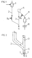
- Embodiments of the process will be explained by way of example with reference to the drawing, in which:
-
Fig. 1 shows a flow diagram of the process; -
Fig. 2 shows a detailed representation ofFig. 1 , -
Fig. 3 shows a flow diagram of the multi-stage process. - Hot solids are conveyed from a heater into a cyclone (1) at a temperature of 650°C to 800°C. In this cyclone (1), a pressure of 4 to 16 bar exists. The fine-grained solids are discharged downwards via a descending line (2). Into the descending line, inert gas (8a), e.g. nitrogen, is introduced, in order to rinse out the reduction gas.
- Subsequent to the descending line, the solids are conveyed upwards into an impact pot (4) by means of an ascending line (3) by supplying carrier gas (9), e.g. nitrogen, in which impact pot the pressure lies in the range from 1 to 2 bar. From said impact pot, the solids are introduced into a briquetting bin (5) and then into a briquetting press (10) by supplying inert gas (8b).
- Due to the continuous inflow of fine-grained solids, a column of these solids is formed in the descending line (2), which column at the same time represents a pressure barrier. This column of solids has a height between 2 and 15 m, and the height thereof can be measured by means of a position meter. The column can be regulated by downwardly draining the same.
- The flow of solids through the descending line (2) depends on the inert gas inflow (8a), which at the same time influences the height of the solids column in the descending line (2). The pressure at the point where the descending line (2) opens into the ascending line (3) is 4 to 16 bar.
- Below the point of intersection of the center line of the descending line (2) with the center line of the ascending line (3), carrier gas (9) is injected via a nozzle (6). The pressure at the nozzle orifice (6) is by 0.5 to 1.5 bar higher than the pressure in the cyclone (1). Via the ascending line (3), the solids are conveyed into an impact pot (4), in which the pressure is 1 to 2 bar. The height of the ascending line from the orifice of the descending line (2) to the overflow bin (4) is 10 to 50 m. The diameter of the ascending line (3) may lie between 0.2 and 1.5 m.
- Around the nozzle orifice (6), a plurality of auxiliary nozzles (7) are disposed, which loosen up the solids and transport the same from the nozzle orifice (6) into the range of influence of the carrier gas (9). The same carrier gas is passed through the nozzles (6) and (7).
-
Fig. 3 shows the conveyance of the solids with a multi-stage decrease in pressure. Hot solids are conveyed from a heater into a cyclone (1) at a temperature of 650°C to 800°C. In this cyclone (1), a pressure of 4 to 16 bar exists. The fine-grained solids are discharged downwards through a descending line (2). Into the descending line, inert gas (8a), e.g. nitrogen, is introduced, in order to rinse out the reduction gas. - Subsequent to the descending line (2), the solids are conveyed upwards into an impact pot (4) by means of an ascending line (3) by supplying carrier gas (9), e.g. nitrogen, in which impact pot the pressure lies in the range from 2 to 8 bar. From said impact pot, the solids are conveyed into a second descending line (11) by supplying further inert gas (8b).
- Subsequent to the descending line, the solids are conveyed upwards into an impact pot (14) by means of a further ascending line (13) by supplying carrier gas (12), e.g. nitrogen, in which impact pot the pressure lies in the range from 1 to 2 bar. From said impact pot, the solids are introduced into a briquetting bin (5) and then into a briquetting press (10) by supplying inert gas (8b).
- To the cyclone (1), 64 t/h direct-reduced iron is supplied with 40,000 Nm3/h H2. The temperature is 730°C, the pressure is 4.5 bar. Upon separation of H2 and solids, the solids are discharged via the descending line (2), which has a diameter of 0.5 m and a length of 16 m. Via line (8a), 70 Nm3/h N2 are supplied for rinsing the H2 contained in the void volume. In the ascending line (3) with a diameter of 0.25 m and a length of 25 m, the solids are conveyed into the impact pot (4) via line (3) by adding 150 Nm3/h N2 through the nozzles (6) and (7). In doing so, the pressure is reduced to 1 bar. From said impact pot, the solids are introduced into a briquetting bin (5) and then into a briquetting press (10) by supplying 30 Nm3/h N2 (8b).
- To the cyclone (1), 64 t/h direct-reduced iron is supplied with 40,000 Nm3/h H2. The temperature is 730°C, the pressure is 4.5 bar. Upon separation of H2 and solids, the solids are discharged via the descending line (2), which has a diameter of 0.5 m and a length of 8 m. Via line (8a), 50 Nm3/h N2 are supplied for rinsing the H2 contained in the void volume. In the ascending line (3) with a diameter of 0.25 m and a length of 10 m, the solids are conveyed into the impact pot (4) via line (3) by adding 150 Nm3/h N2 through the nozzles (6) and (7), in which impact pot a pressure of 3.0 bar is obtained. From said impact pot, the solids are discharged via the descending line (11), which has a diameter of 0.5 m and a length of 8 m. Via lines (8b) and (8c), 50 Nm3/h N2 are supplied for further removing the H2 contained in the void volume.
- In the ascending line (13) with a diameter of 0.25 m and a length of 15 m, the solids are conveyed into the impact pot by adding 100 Nm3/h N2 (12) via line (13), in which impact pot a pressure of 1 bar exists. From said impact pot, the solids are introduced into a briquetting bin (5) and then into a briquetting press (10) by supplying 30 Nm3/h N2 (8d).
Claims (5)
- A process of continuously conveying granular solids from a first zone through a descending line and via an ascending line to a second zone with a pressure which is lower than in the first zone, by means of a gaseous medium, wherein the inflow of the gaseous medium is effected through an upwardly directed nozzle at the point where the descending line opens into the ascending line, characterized in that the first zone is at a pressure of 4 to 16 bar and that the pressure in the second zone is 3 to 15 bar lower than the pressure of the first zone, and that the solids weight in the ascending line lies in the range from 0.3 to 0.8 times the bulk weight.
- The process as claimed in claim 1, characterized in that the nozzle orifice for the inflow of the gaseous medium is disposed at a distance of 0.5 to 8 times the hydraulic diameter of the nozzle orifice below the point of intersection of the tube axes.
- The process as claimed in claim 2, characterized in that at least one auxiliary nozzle is disposed beside the conveying nozzle.
- The process as claimed in claims 1, characterized in that the solids weight in the ascending line lies in the range from 0.4 to 0.7 times the bulk weight.
- The process as claimed in claim 1, characterized in that the solids are conveyed in a multi-stage decrease in pressure via two descending lines and via two ascending lines.
Applications Claiming Priority (3)
| Application Number | Priority Date | Filing Date | Title |
|---|---|---|---|
| DE10116892A DE10116892A1 (en) | 2001-04-04 | 2001-04-04 | Process for conveying granular solids |
| DE10116892 | 2001-04-04 | ||
| PCT/EP2002/002630 WO2002081074A1 (en) | 2001-04-04 | 2002-03-09 | Process of conveying granular solids |
Publications (2)
| Publication Number | Publication Date |
|---|---|
| EP1372838A1 EP1372838A1 (en) | 2004-01-02 |
| EP1372838B1 true EP1372838B1 (en) | 2014-05-07 |
Family
ID=7680433
Family Applications (1)
| Application Number | Title | Priority Date | Filing Date |
|---|---|---|---|
| EP02708353.4A Expired - Lifetime EP1372838B1 (en) | 2001-04-04 | 2002-03-09 | Process of conveying granular solids |
Country Status (12)
| Country | Link |
|---|---|
| US (1) | US6666629B2 (en) |
| EP (1) | EP1372838B1 (en) |
| CN (1) | CN1226077C (en) |
| AR (1) | AR033074A1 (en) |
| AU (1) | AU2002242726B2 (en) |
| BR (2) | BRPI0208569B1 (en) |
| DE (1) | DE10116892A1 (en) |
| EG (1) | EG23097A (en) |
| MY (1) | MY136337A (en) |
| SA (1) | SA02230227B1 (en) |
| WO (1) | WO2002081074A1 (en) |
| ZA (1) | ZA200306482B (en) |
Families Citing this family (41)
| Publication number | Priority date | Publication date | Assignee | Title |
|---|---|---|---|---|
| US8788092B2 (en) | 2000-01-24 | 2014-07-22 | Irobot Corporation | Obstacle following sensor scheme for a mobile robot |
| US8412377B2 (en) | 2000-01-24 | 2013-04-02 | Irobot Corporation | Obstacle following sensor scheme for a mobile robot |
| US6956348B2 (en) | 2004-01-28 | 2005-10-18 | Irobot Corporation | Debris sensor for cleaning apparatus |
| US7571511B2 (en) | 2002-01-03 | 2009-08-11 | Irobot Corporation | Autonomous floor-cleaning robot |
| US6690134B1 (en) | 2001-01-24 | 2004-02-10 | Irobot Corporation | Method and system for robot localization and confinement |
| US7663333B2 (en) | 2001-06-12 | 2010-02-16 | Irobot Corporation | Method and system for multi-mode coverage for an autonomous robot |
| US8396592B2 (en) | 2001-06-12 | 2013-03-12 | Irobot Corporation | Method and system for multi-mode coverage for an autonomous robot |
| US9128486B2 (en) | 2002-01-24 | 2015-09-08 | Irobot Corporation | Navigational control system for a robotic device |
| US8428778B2 (en) | 2002-09-13 | 2013-04-23 | Irobot Corporation | Navigational control system for a robotic device |
| US8386081B2 (en) | 2002-09-13 | 2013-02-26 | Irobot Corporation | Navigational control system for a robotic device |
| FR2858972B1 (en) * | 2003-08-19 | 2006-02-17 | Inst Francais Du Petrole | DEVICE FOR TRANSPORTING SOLID GRANULAR PARTICLES WITH CONTROLLED FLOW |
| US7332890B2 (en) | 2004-01-21 | 2008-02-19 | Irobot Corporation | Autonomous robot auto-docking and energy management systems and methods |
| DE112005000738T5 (en) | 2004-03-29 | 2007-04-26 | Evolution Robotics, Inc., Pasadena | Method and device for determining position using reflected light sources |
| WO2006002385A1 (en) | 2004-06-24 | 2006-01-05 | Irobot Corporation | Programming and diagnostic tool for a mobile robot |
| US7706917B1 (en) | 2004-07-07 | 2010-04-27 | Irobot Corporation | Celestial navigation system for an autonomous robot |
| US8972052B2 (en) | 2004-07-07 | 2015-03-03 | Irobot Corporation | Celestial navigation system for an autonomous vehicle |
| ATE523130T1 (en) | 2005-02-18 | 2011-09-15 | Irobot Corp | SELF-DRIVEN SURFACE CLEANING ROBOT FOR WET AND DRY CLEANING |
| US7620476B2 (en) | 2005-02-18 | 2009-11-17 | Irobot Corporation | Autonomous surface cleaning robot for dry cleaning |
| US8392021B2 (en) | 2005-02-18 | 2013-03-05 | Irobot Corporation | Autonomous surface cleaning robot for wet cleaning |
| US8930023B2 (en) | 2009-11-06 | 2015-01-06 | Irobot Corporation | Localization by learning of wave-signal distributions |
| EP1969438B1 (en) | 2005-12-02 | 2009-09-09 | iRobot Corporation | Modular robot |
| EP2829939B1 (en) | 2005-12-02 | 2019-11-13 | iRobot Corporation | Autonomous coverage robot navigation system |
| KR101300493B1 (en) | 2005-12-02 | 2013-09-02 | 아이로보트 코퍼레이션 | Coverage robot mobility |
| EP2533120B1 (en) | 2005-12-02 | 2019-01-16 | iRobot Corporation | Robot system |
| EP2548492B1 (en) | 2006-05-19 | 2016-04-20 | iRobot Corporation | Removing debris from cleaning robots |
| US8417383B2 (en) | 2006-05-31 | 2013-04-09 | Irobot Corporation | Detecting robot stasis |
| DE102007009758B4 (en) * | 2007-02-27 | 2024-11-28 | Metso Outotec Finland Oy | Method and device for controlling a solid flow |
| DE102007009759A1 (en) * | 2007-02-27 | 2008-08-28 | Outotec Oyj | Distribution of solid flow drawn-off from cyclone/fluidized bed container, by conducting solid flow over first down pipe and then fluidizing at bottom of down pipe by supplying carrier gas, and conveying a part of solid flow towards the top |
| KR20140123110A (en) | 2007-05-09 | 2014-10-21 | 아이로보트 코퍼레이션 | Compact autonomous coverage robot |
| US8075227B2 (en) * | 2007-11-30 | 2011-12-13 | Uop Llc | Device to transfer catalyst from a low pressure vessel to a high pressure vessel and purge the transferred catalyst |
| US7600950B2 (en) * | 2007-11-30 | 2009-10-13 | Uop Llc | Device to transfer catalyst from a low pressure vessel to a high pressure vessel and purge the transferred catalyst |
| CN102724903B (en) | 2010-02-16 | 2015-11-25 | 艾罗伯特公司 | vacuum cleaner brush |
| DE102010022773B4 (en) | 2010-06-04 | 2012-10-04 | Outotec Oyj | Process and plant for the production of pig iron |
| JP5868839B2 (en) * | 2012-12-27 | 2016-02-24 | 三菱重工業株式会社 | Char discharge pipe |
| US9207729B2 (en) * | 2013-06-07 | 2015-12-08 | Apple Inc. | Computer Architecture |
| JP6109796B2 (en) * | 2014-09-16 | 2017-04-05 | 三菱日立パワーシステムズ株式会社 | Powder conveying device and char recovery device |
| CN107531430B (en) * | 2015-06-24 | 2020-07-28 | 环球油品公司 | A device for transporting catalyst |
| US11629016B2 (en) * | 2019-01-18 | 2023-04-18 | Tricoya Technologies Ltd | System and a method for transferring solid particles from a first environment at a first gas pressure to a second environment at a second gas pressure |
| CN109911626A (en) * | 2019-04-23 | 2019-06-21 | 长春万荣装饰材料有限公司 | A pneumatic conveying device for conveying powder, sand and other materials |
| CN113274952B (en) * | 2021-05-19 | 2022-07-26 | 浙江大学 | Method for stably controlling external circulation of fluidized bed |
| AU2023477779A1 (en) * | 2023-12-22 | 2026-07-02 | Sms Group Gmbh | System and method for conveying material |
Family Cites Families (11)
| Publication number | Priority date | Publication date | Assignee | Title |
|---|---|---|---|---|
| US2684872A (en) | 1950-03-13 | 1954-07-27 | Union Oil Co | Conveyance of granular solids |
| US2684873A (en) | 1950-03-13 | 1954-07-27 | Union Oil Co | Method and apparatus for the conveyance of granular solids |
| US2684868A (en) | 1951-01-16 | 1954-07-27 | Union Oil Co | Conveyance of granular solids |
| US2978279A (en) * | 1951-12-20 | 1961-04-04 | Socony Mobil Oil Co Inc | Method and apparatus for transferring contact material |
| US2750181A (en) * | 1952-01-03 | 1956-06-12 | Phillips Petroleum Co | Pebble heater |
| US3106429A (en) * | 1960-05-31 | 1963-10-08 | Sun Oil Co | Elevation of granular solids |
| US3389076A (en) * | 1966-06-30 | 1968-06-18 | Exxon Research Engineering Co | Fluid solids transport |
| US3874739A (en) * | 1973-08-07 | 1975-04-01 | Exxon Research Engineering Co | Method and apparatus for the transfer of entrained solids |
| DE2939029C2 (en) * | 1979-09-27 | 1986-08-07 | Bergwerksverband Gmbh | Feeding device for fine-grain bulk material on an entrained flow pipe |
| US4327055A (en) * | 1979-12-31 | 1982-04-27 | Exxon Research & Engineering Co. | Continuous catalyst unloading device |
| DE3413750A1 (en) * | 1984-04-12 | 1985-10-24 | Metallgesellschaft Ag, 6000 Frankfurt | DEVICE FOR DISCHARGING FINE GRAIN MATERIAL |
-
2001
- 2001-04-04 DE DE10116892A patent/DE10116892A1/en not_active Withdrawn
-
2002
- 2002-03-09 BR BRPI0208569-0A patent/BRPI0208569B1/en unknown
- 2002-03-09 AU AU2002242726A patent/AU2002242726B2/en not_active Expired
- 2002-03-09 WO PCT/EP2002/002630 patent/WO2002081074A1/en not_active Ceased
- 2002-03-09 CN CNB028066855A patent/CN1226077C/en not_active Expired - Lifetime
- 2002-03-09 BR BR0208569-0A patent/BR0208569A/en active IP Right Grant
- 2002-03-09 EP EP02708353.4A patent/EP1372838B1/en not_active Expired - Lifetime
- 2002-03-27 AR ARP020101153A patent/AR033074A1/en unknown
- 2002-03-29 MY MYPI20021149A patent/MY136337A/en unknown
- 2002-03-31 EG EG20020339A patent/EG23097A/en active
- 2002-04-02 US US10/114,333 patent/US6666629B2/en not_active Expired - Lifetime
- 2002-07-30 SA SA02230227A patent/SA02230227B1/en unknown
-
2003
- 2003-08-20 ZA ZA200306482A patent/ZA200306482B/en unknown
Also Published As
| Publication number | Publication date |
|---|---|
| US6666629B2 (en) | 2003-12-23 |
| MY136337A (en) | 2008-09-30 |
| BR0208569A (en) | 2004-03-30 |
| EP1372838A1 (en) | 2004-01-02 |
| DE10116892A1 (en) | 2002-10-17 |
| CN1498130A (en) | 2004-05-19 |
| WO2002081074A1 (en) | 2002-10-17 |
| US20020146291A1 (en) | 2002-10-10 |
| AU2002242726B2 (en) | 2007-01-25 |
| AR033074A1 (en) | 2003-12-03 |
| CN1226077C (en) | 2005-11-09 |
| ZA200306482B (en) | 2004-08-20 |
| SA02230227B1 (en) | 2007-04-07 |
| BRPI0208569B1 (en) | 2019-04-24 |
| EG23097A (en) | 2004-03-31 |
Similar Documents
| Publication | Publication Date | Title |
|---|---|---|
| AU2002242726B2 (en) | Process of conveying granular solids | |
| AU2002242726A1 (en) | Process of conveying granular solids | |
| US4401402A (en) | Liquid seal lock hoppers and method of utilizing same | |
| JP4558941B2 (en) | Method and apparatus for emptying a polymerization reactor | |
| US5175943A (en) | Solids feed system and method for feeding fluidized beds | |
| AU685947B2 (en) | Improved gas phase fluidized bed polyolefin polymerization process using gas-solids tangential flow | |
| US3729105A (en) | Liquid sealed solids lock hopper | |
| BG62364B1 (en) | Device and method of polymerization of olefin(s) in a gas phase | |
| CA1118695A (en) | Method and apparatus for preventing coking in fluidized bed reactors for cracking heavy hydrocarbon oil | |
| US2985517A (en) | Method and apparatus for contacting and conveying of fluidized solids and fluids to be contacted therewith | |
| FI86075B (en) | FOERFARANDE FOER FRAMSTAELLNING AV EN VAETE OCH TROLMONOXID INNEHAOLLANDE GAS UR FASTA BRAENSLEN SAMT FOERGASNINGSREAKTOR FOER GENOMFOERING AV FOERFARANDET. | |
| CN101107066B (en) | Apparatus and method for removing polymer from a gas phase polymerization reactor | |
| US8703087B2 (en) | Apparatus and method for top removal of granular material from a fluidized bed deposition reactor | |
| US2624695A (en) | Transfer of granular materials | |
| US2726136A (en) | Solid particle transfer process and apparatus | |
| EP0032064B1 (en) | System for the continuous conveyance of catalyst from a fluidized bed in a regenerator | |
| EA008032B1 (en) | Direct smelting plant and process | |
| US4094651A (en) | Process for pseudohydrostatic feeding of solids into a reactor | |
| AU2003209752B2 (en) | Methods and devices for heating a continuous flow of solids | |
| EP0118929B1 (en) | Process for transporting particulate material | |
| EP0236320A1 (en) | A particulate solid feeding device | |
| US2730407A (en) | Conveyance of granular solids | |
| AU2002344993B2 (en) | Method and device for treating particulate material | |
| NZ214191A (en) | Transferring solid particles to point of higher pressure | |
| GB842299A (en) | A process involving the treatment of fluid material by contacting it with granular solid material |
Legal Events
| Date | Code | Title | Description |
|---|---|---|---|
| PUAI | Public reference made under article 153(3) epc to a published international application that has entered the european phase |
Free format text: ORIGINAL CODE: 0009012 |
|
| 17P | Request for examination filed |
Effective date: 20030911 |
|
| AK | Designated contracting states |
Kind code of ref document: A1 Designated state(s): AT BE CH CY DE DK ES FI FR GB GR IE IT LI LU MC NL PT SE TR |
|
| AX | Request for extension of the european patent |
Extension state: AL LT LV MK RO SI |
|
| RIN1 | Information on inventor provided before grant (corrected) |
Inventor name: FORMANEK, LOTHAR Inventor name: SNEYD, STUART Inventor name: HIRSCH, MARTIN |
|
| RIC1 | Information provided on ipc code assigned before grant |
Ipc: B65G 53/52 20060101ALI20131002BHEP Ipc: C21B 13/00 20060101ALI20131002BHEP Ipc: B01J 8/00 20060101AFI20131002BHEP |
|
| RAP1 | Party data changed (applicant data changed or rights of an application transferred) |
Owner name: OUTOTEC OYJ |
|
| GRAP | Despatch of communication of intention to grant a patent |
Free format text: ORIGINAL CODE: EPIDOSNIGR1 |
|
| INTG | Intention to grant announced |
Effective date: 20140123 |
|
| GRAS | Grant fee paid |
Free format text: ORIGINAL CODE: EPIDOSNIGR3 |
|
| GRAA | (expected) grant |
Free format text: ORIGINAL CODE: 0009210 |
|
| AK | Designated contracting states |
Kind code of ref document: B1 Designated state(s): BE DE |
|
| REG | Reference to a national code |
Ref country code: DE Ref legal event code: R096 Ref document number: 60246257 Country of ref document: DE Effective date: 20140618 |
|
| REG | Reference to a national code |
Ref country code: DE Ref legal event code: R097 Ref document number: 60246257 Country of ref document: DE |
|
| PLBE | No opposition filed within time limit |
Free format text: ORIGINAL CODE: 0009261 |
|
| STAA | Information on the status of an ep patent application or granted ep patent |
Free format text: STATUS: NO OPPOSITION FILED WITHIN TIME LIMIT |
|
| 26N | No opposition filed |
Effective date: 20150210 |
|
| REG | Reference to a national code |
Ref country code: DE Ref legal event code: R097 Ref document number: 60246257 Country of ref document: DE Effective date: 20150210 |
|
| PGFP | Annual fee paid to national office [announced via postgrant information from national office to epo] |
Ref country code: BE Payment date: 20210319 Year of fee payment: 20 Ref country code: DE Payment date: 20210319 Year of fee payment: 20 |
|
| REG | Reference to a national code |
Ref country code: DE Ref legal event code: R071 Ref document number: 60246257 Country of ref document: DE |
|
| REG | Reference to a national code |
Ref country code: BE Ref legal event code: MK Effective date: 20220309 |