EP1372763B1 - Syringe and needle shield assembly and method of sterilizing such assembly - Google Patents
Syringe and needle shield assembly and method of sterilizing such assembly Download PDFInfo
- Publication number
- EP1372763B1 EP1372763B1 EP02717611A EP02717611A EP1372763B1 EP 1372763 B1 EP1372763 B1 EP 1372763B1 EP 02717611 A EP02717611 A EP 02717611A EP 02717611 A EP02717611 A EP 02717611A EP 1372763 B1 EP1372763 B1 EP 1372763B1
- Authority
- EP
- European Patent Office
- Prior art keywords
- needle
- bevels
- shield
- needle shield
- syringe
- Prior art date
- Legal status (The legal status is an assumption and is not a legal conclusion. Google has not performed a legal analysis and makes no representation as to the accuracy of the status listed.)
- Expired - Lifetime
Links
- 238000000034 method Methods 0.000 title claims description 10
- 230000001954 sterilising effect Effects 0.000 title abstract description 46
- PPBRXRYQALVLMV-UHFFFAOYSA-N Styrene Chemical compound C=CC1=CC=CC=C1 PPBRXRYQALVLMV-UHFFFAOYSA-N 0.000 claims abstract description 87
- 238000004659 sterilization and disinfection Methods 0.000 claims abstract description 48
- 229920001971 elastomer Polymers 0.000 claims abstract description 40
- 125000000383 tetramethylene group Chemical group [H]C([H])([*:1])C([H])([H])C([H])([H])C([H])([H])[*:2] 0.000 claims abstract description 34
- VGGSQFUCUMXWEO-UHFFFAOYSA-N Ethene Chemical compound C=C VGGSQFUCUMXWEO-UHFFFAOYSA-N 0.000 claims abstract description 33
- 239000005977 Ethylene Substances 0.000 claims abstract description 33
- IAYPIBMASNFSPL-UHFFFAOYSA-N Ethylene oxide Chemical compound C1CO1 IAYPIBMASNFSPL-UHFFFAOYSA-N 0.000 claims description 37
- 239000000314 lubricant Substances 0.000 claims description 22
- 239000000806 elastomer Substances 0.000 claims description 12
- 239000003086 colorant Substances 0.000 claims description 11
- 239000006229 carbon black Substances 0.000 claims description 10
- 229920001169 thermoplastic Polymers 0.000 claims description 8
- 239000004416 thermosoftening plastic Substances 0.000 claims description 8
- 238000004519 manufacturing process Methods 0.000 claims description 6
- 229920002545 silicone oil Polymers 0.000 claims description 4
- 239000012466 permeate Substances 0.000 claims description 3
- 239000011248 coating agent Substances 0.000 claims 1
- 238000000576 coating method Methods 0.000 claims 1
- 229920002725 thermoplastic elastomer Polymers 0.000 abstract description 56
- 230000035515 penetration Effects 0.000 abstract description 43
- 239000005060 rubber Substances 0.000 abstract description 28
- 238000012360 testing method Methods 0.000 description 31
- 229920002633 Kraton (polymer) Polymers 0.000 description 20
- 229920003052 natural elastomer Polymers 0.000 description 19
- 229920001194 natural rubber Polymers 0.000 description 19
- 230000036407 pain Effects 0.000 description 17
- 238000002347 injection Methods 0.000 description 16
- 239000007924 injection Substances 0.000 description 16
- 244000043261 Hevea brasiliensis Species 0.000 description 13
- 239000012530 fluid Substances 0.000 description 13
- 239000003814 drug Substances 0.000 description 12
- 229920003051 synthetic elastomer Polymers 0.000 description 11
- 239000005061 synthetic rubber Substances 0.000 description 11
- 230000008901 benefit Effects 0.000 description 10
- 229920000642 polymer Polymers 0.000 description 10
- 230000006872 improvement Effects 0.000 description 9
- 239000000463 material Substances 0.000 description 9
- 210000003491 skin Anatomy 0.000 description 9
- -1 styrene-ethylene-butylene-styrene Chemical class 0.000 description 8
- 230000007704 transition Effects 0.000 description 8
- 241001631457 Cannula Species 0.000 description 7
- 238000013461 design Methods 0.000 description 7
- 230000035699 permeability Effects 0.000 description 7
- 229920003031 santoprene Polymers 0.000 description 7
- 229940079593 drug Drugs 0.000 description 6
- 239000004033 plastic Substances 0.000 description 6
- 229920003023 plastic Polymers 0.000 description 6
- 229960005486 vaccine Drugs 0.000 description 6
- 230000000712 assembly Effects 0.000 description 5
- 238000000429 assembly Methods 0.000 description 5
- 230000015572 biosynthetic process Effects 0.000 description 5
- 239000000203 mixture Substances 0.000 description 5
- 230000000694 effects Effects 0.000 description 4
- 239000000945 filler Substances 0.000 description 4
- 238000007654 immersion Methods 0.000 description 4
- 230000009467 reduction Effects 0.000 description 4
- 230000032683 aging Effects 0.000 description 3
- 238000004891 communication Methods 0.000 description 3
- 239000004205 dimethyl polysiloxane Substances 0.000 description 3
- 210000002615 epidermis Anatomy 0.000 description 3
- 239000011521 glass Substances 0.000 description 3
- 229920000435 poly(dimethylsiloxane) Polymers 0.000 description 3
- 229910001220 stainless steel Inorganic materials 0.000 description 3
- 239000010935 stainless steel Substances 0.000 description 3
- 210000001519 tissue Anatomy 0.000 description 3
- 231100000331 toxic Toxicity 0.000 description 3
- 230000002588 toxic effect Effects 0.000 description 3
- VSKJLJHPAFKHBX-UHFFFAOYSA-N 2-methylbuta-1,3-diene;styrene Chemical compound CC(=C)C=C.C=CC1=CC=CC=C1.C=CC1=CC=CC=C1 VSKJLJHPAFKHBX-UHFFFAOYSA-N 0.000 description 2
- 239000004698 Polyethylene Substances 0.000 description 2
- 230000005540 biological transmission Effects 0.000 description 2
- FACXGONDLDSNOE-UHFFFAOYSA-N buta-1,3-diene;styrene Chemical compound C=CC=C.C=CC1=CC=CC=C1.C=CC1=CC=CC=C1 FACXGONDLDSNOE-UHFFFAOYSA-N 0.000 description 2
- 238000007405 data analysis Methods 0.000 description 2
- 238000001514 detection method Methods 0.000 description 2
- 239000013536 elastomeric material Substances 0.000 description 2
- 238000007918 intramuscular administration Methods 0.000 description 2
- 230000014759 maintenance of location Effects 0.000 description 2
- 238000005259 measurement Methods 0.000 description 2
- 244000005700 microbiome Species 0.000 description 2
- 239000000178 monomer Substances 0.000 description 2
- 238000000465 moulding Methods 0.000 description 2
- 238000004806 packaging method and process Methods 0.000 description 2
- 229920000573 polyethylene Polymers 0.000 description 2
- 229920001296 polysiloxane Polymers 0.000 description 2
- 229940071643 prefilled syringe Drugs 0.000 description 2
- 230000008569 process Effects 0.000 description 2
- 239000000047 product Substances 0.000 description 2
- 230000004044 response Effects 0.000 description 2
- 238000004088 simulation Methods 0.000 description 2
- 238000010561 standard procedure Methods 0.000 description 2
- 229920000468 styrene butadiene styrene block copolymer Polymers 0.000 description 2
- 238000007920 subcutaneous administration Methods 0.000 description 2
- 239000007929 subcutaneous injection Substances 0.000 description 2
- 238000010254 subcutaneous injection Methods 0.000 description 2
- 238000011282 treatment Methods 0.000 description 2
- 230000000007 visual effect Effects 0.000 description 2
- XLYOFNOQVPJJNP-UHFFFAOYSA-N water Substances O XLYOFNOQVPJJNP-UHFFFAOYSA-N 0.000 description 2
- 229920002943 EPDM rubber Polymers 0.000 description 1
- 208000012266 Needlestick injury Diseases 0.000 description 1
- 239000004743 Polypropylene Substances 0.000 description 1
- 239000004793 Polystyrene Substances 0.000 description 1
- 229910000831 Steel Inorganic materials 0.000 description 1
- 238000005299 abrasion Methods 0.000 description 1
- 230000000903 blocking effect Effects 0.000 description 1
- 229920005549 butyl rubber Polymers 0.000 description 1
- 239000000919 ceramic Substances 0.000 description 1
- 238000011284 combination treatment Methods 0.000 description 1
- 239000002131 composite material Substances 0.000 description 1
- 238000005336 cracking Methods 0.000 description 1
- 230000001419 dependent effect Effects 0.000 description 1
- 238000009826 distribution Methods 0.000 description 1
- 239000013013 elastic material Substances 0.000 description 1
- HQQADJVZYDDRJT-UHFFFAOYSA-N ethene;prop-1-ene Chemical group C=C.CC=C HQQADJVZYDDRJT-UHFFFAOYSA-N 0.000 description 1
- 238000011156 evaluation Methods 0.000 description 1
- 235000013305 food Nutrition 0.000 description 1
- 238000009472 formulation Methods 0.000 description 1
- 229910052736 halogen Inorganic materials 0.000 description 1
- 150000002367 halogens Chemical class 0.000 description 1
- 238000003780 insertion Methods 0.000 description 1
- 230000037431 insertion Effects 0.000 description 1
- 239000007927 intramuscular injection Substances 0.000 description 1
- 238000010255 intramuscular injection Methods 0.000 description 1
- 239000007788 liquid Substances 0.000 description 1
- 238000005461 lubrication Methods 0.000 description 1
- 238000010999 medical injection Methods 0.000 description 1
- 238000012986 modification Methods 0.000 description 1
- 230000004048 modification Effects 0.000 description 1
- 210000001577 neostriatum Anatomy 0.000 description 1
- 230000037324 pain perception Effects 0.000 description 1
- 229920001155 polypropylene Polymers 0.000 description 1
- 229920002223 polystyrene Polymers 0.000 description 1
- 229920002745 polystyrene-block- poly(ethylene /butylene) Polymers 0.000 description 1
- 239000008213 purified water Substances 0.000 description 1
- 239000011347 resin Substances 0.000 description 1
- 229920005989 resin Polymers 0.000 description 1
- 238000010058 rubber compounding Methods 0.000 description 1
- 238000007789 sealing Methods 0.000 description 1
- 239000003566 sealing material Substances 0.000 description 1
- 230000035945 sensitivity Effects 0.000 description 1
- 238000000926 separation method Methods 0.000 description 1
- 229920002379 silicone rubber Polymers 0.000 description 1
- 239000004945 silicone rubber Substances 0.000 description 1
- 239000010959 steel Substances 0.000 description 1
- 229920006132 styrene block copolymer Polymers 0.000 description 1
- 229920003048 styrene butadiene rubber Polymers 0.000 description 1
- 238000006467 substitution reaction Methods 0.000 description 1
- 229920001897 terpolymer Polymers 0.000 description 1
Images


Classifications
-
- B—PERFORMING OPERATIONS; TRANSPORTING
- B24—GRINDING; POLISHING
- B24B—MACHINES, DEVICES, OR PROCESSES FOR GRINDING OR POLISHING; DRESSING OR CONDITIONING OF ABRADING SURFACES; FEEDING OF GRINDING, POLISHING, OR LAPPING AGENTS
- B24B19/00—Single-purpose machines or devices for particular grinding operations not covered by any other main group
- B24B19/16—Single-purpose machines or devices for particular grinding operations not covered by any other main group for grinding sharp-pointed workpieces, e.g. needles, pens, fish hooks, tweezers or record player styli
-
- A—HUMAN NECESSITIES
- A61—MEDICAL OR VETERINARY SCIENCE; HYGIENE
- A61M—DEVICES FOR INTRODUCING MEDIA INTO, OR ONTO, THE BODY; DEVICES FOR TRANSDUCING BODY MEDIA OR FOR TAKING MEDIA FROM THE BODY; DEVICES FOR PRODUCING OR ENDING SLEEP OR STUPOR
- A61M5/00—Devices for bringing media into the body in a subcutaneous, intra-vascular or intramuscular way; Accessories therefor, e.g. filling or cleaning devices, arm-rests
- A61M5/178—Syringes
- A61M5/31—Details
- A61M5/32—Needles; Details of needles pertaining to their connection with syringe or hub; Accessories for bringing the needle into, or holding the needle on, the body; Devices for protection of needles
- A61M5/3202—Devices for protection of the needle before use, e.g. caps
-
- A—HUMAN NECESSITIES
- A61—MEDICAL OR VETERINARY SCIENCE; HYGIENE
- A61M—DEVICES FOR INTRODUCING MEDIA INTO, OR ONTO, THE BODY; DEVICES FOR TRANSDUCING BODY MEDIA OR FOR TAKING MEDIA FROM THE BODY; DEVICES FOR PRODUCING OR ENDING SLEEP OR STUPOR
- A61M5/00—Devices for bringing media into the body in a subcutaneous, intra-vascular or intramuscular way; Accessories therefor, e.g. filling or cleaning devices, arm-rests
- A61M5/178—Syringes
- A61M5/31—Details
- A61M5/32—Needles; Details of needles pertaining to their connection with syringe or hub; Accessories for bringing the needle into, or holding the needle on, the body; Devices for protection of needles
- A61M5/3286—Needle tip design, e.g. for improved penetration
-
- A—HUMAN NECESSITIES
- A61—MEDICAL OR VETERINARY SCIENCE; HYGIENE
- A61M—DEVICES FOR INTRODUCING MEDIA INTO, OR ONTO, THE BODY; DEVICES FOR TRANSDUCING BODY MEDIA OR FOR TAKING MEDIA FROM THE BODY; DEVICES FOR PRODUCING OR ENDING SLEEP OR STUPOR
- A61M5/00—Devices for bringing media into the body in a subcutaneous, intra-vascular or intramuscular way; Accessories therefor, e.g. filling or cleaning devices, arm-rests
- A61M5/178—Syringes
- A61M5/31—Details
- A61M2005/3103—Leak prevention means for distal end of syringes, i.e. syringe end for mounting a needle
- A61M2005/3107—Leak prevention means for distal end of syringes, i.e. syringe end for mounting a needle for needles
- A61M2005/3109—Caps sealing the needle bore by use of, e.g. air-hardening adhesive, elastomer or epoxy resin
-
- A—HUMAN NECESSITIES
- A61—MEDICAL OR VETERINARY SCIENCE; HYGIENE
- A61M—DEVICES FOR INTRODUCING MEDIA INTO, OR ONTO, THE BODY; DEVICES FOR TRANSDUCING BODY MEDIA OR FOR TAKING MEDIA FROM THE BODY; DEVICES FOR PRODUCING OR ENDING SLEEP OR STUPOR
- A61M2205/00—General characteristics of the apparatus
- A61M2205/19—Constructional features of carpules, syringes or blisters
- A61M2205/192—Avoiding coring, e.g. preventing formation of particles during puncture
- A61M2205/195—Avoiding coring, e.g. preventing formation of particles during puncture by the needle tip shape
Definitions
- a hypodermic syringe typically includes a generally tubular barrel portion, which may be formed of glass or plastic, a plunger having a stopper typically formed of an elastomeric material, such as rubber or synthetic rubber, and a needle cannula typically formed from an elongated tube having a fluid-conducting lumen.
- a needle shield includes an open end, a closed end, and a needle passage through the open end which receives the sharp end of the syringe needle cannula.
- EP-A-1,008,359 describes a medical container having a pre-sealed nozzle sealed with a cap which can be formed from a wide range of materials of which 12 are mentioned and styrene-ethylene-butylene-styrene block copolymer is one.
- a needle cannula has a central lumen defining an axis through the needle cannula.
- the multi-beveled cannula needle point defines an opening to the lumen for the passage of fluids between a medical delivery device, such as a syringe, and a patient or vessel.
- the multi-beveled point preferably includes a primary bevel, a pair of tip bevels, and a pair of middle bevels.
- thermoplastic elastomers are characterized as having a low gas permeability, resulting in slow transmission of the sterilization gas into the passage in the needle shield containing the needle cannula.
- ethylene oxide gas is toxic, all of the sterilization gas must be removed from the needle shield before packaging.
- the syringe assembly is quarantined until substantially all of the sterilization gas permeates out through the shield.
- a styrene block poly(ethylene butylene) thermoplastic elastomer has a relatively high gas permeability to ethylene oxide gas as established by testing for residual gas in the shield following sterilization.
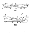
- Figure 6 is a side view of the multi-beveled needle tip of Figure 4.
- Figure 8 is a second view of a multi-beveled needle cannula tip in accordance with the present invention, depicting the needle cannula rotated about the central axis at a first rotational angle and inclined at a planar angle with respect to an imaginary plane extending through the central axis for forming the middle bevels;
- Sharpness as perceived by the nurse, was measured on a visual analog scale (VAS), and ranges from zero (excellent sharpness) to 100 (dull) as perceived by the nurse was recorded. Each sharpness VAS entry was measured by two different people, with the average measurement being used for the data analysis. The feeling of the injection as perceived by the nurse was qualified with five integer scale response variables. The overall feel of the injection was rated on a 13-point scale. The initial resistance, smoothness of penetration and roughness/shatters/ripping response variables were measured on a 4-point scale. In addition, each of the five responsible variables was oriented such that the lower scores were the preferred scores regarding product performance.
- hypodermic syringe assemblies including prefilled syringes must be sterilized before use.
- hypodermic syringes are sterilized by immersion in ethylene oxide or steam as described above.
- ethylene oxide gas is toxic, the gas must be removed prior to packaging.
- FIG. 6 exemplifies the side profile of multi-beveled needle tip 120 formed in accordance with the present invention.
- Intercept 138a is reduced in height to an extent that when viewed from the side, middle bevel 132a and tip bevel 134a appear to provide a substantially-straight profile.
- middle and tip bevels 132b, 134b when viewed in side profile, define an angle " ⁇ " that is nearly 180° as measured about intercept 138b.
- the effect is a more continuous bevel face 140 free of abrupt intercepts 138a, 138b (or for that matter, transitions 131 demarcating the primary middle bevels), resulting in a needle tip requiring less penetration force.
- the effective outer diameter of needle point 120 is reduced, helping to reduce needle penetration forces.
Landscapes
- Health & Medical Sciences (AREA)
- Engineering & Computer Science (AREA)
- Heart & Thoracic Surgery (AREA)
- Vascular Medicine (AREA)
- Anesthesiology (AREA)
- Biomedical Technology (AREA)
- Hematology (AREA)
- Life Sciences & Earth Sciences (AREA)
- Animal Behavior & Ethology (AREA)
- General Health & Medical Sciences (AREA)
- Public Health (AREA)
- Veterinary Medicine (AREA)
- Mechanical Engineering (AREA)
- Infusion, Injection, And Reservoir Apparatuses (AREA)
- Apparatus For Disinfection Or Sterilisation (AREA)
Abstract
Description
- The present invention relates to hypodermic syringes, particularly sterilized prefilled or prefillable syringes, having a needle shield or sheath providing reduced needle penetration force, a method of making a sterilized syringe assembly and an improved multibeveled needle tip configuration.
- A hypodermic syringe typically includes a generally tubular barrel portion, which may be formed of glass or plastic, a plunger having a stopper typically formed of an elastomeric material, such as rubber or synthetic rubber, and a needle cannula typically formed from an elongated tube having a fluid-conducting lumen. Such syringes may be prefilled with a medicament, drug or vaccine which require a shield or sheath enclosing the sharp end of the needle cannula typically formed of rubber or synthetic rubber. A needle shield includes an open end, a closed end, and a needle passage through the open end which receives the sharp end of the syringe needle cannula. As will be understood, hypodermic syringes must be sterilized prior to use by the healthcare worker or patient and such syringes are typically sterilized by the manufacturer and generally sealed in a plastic container ready for use.
- A preferred method of sterilizing hypodermic syringes, particularly prefillable or prefilled syringes, is to "immerse" the syringe assembly in a sterilizing gas, such as ethylene oxide. Although there are several industry recognized methods of gas sterilization, such methods depend upon permeation of the sterilization gas into the passage of the needle shield to sterilize the syringe needle cannula. However, natural and synthetic rubber and vulcanizate thermoplastic elastomers are characterized as having a low gas permeability. Further, ethylene oxide gas, which is commonly used for gas sterilization. Alternatively, steam sterilization may also be used, but is generally limited to subsequent or "terminal" sterilization. As used herein, "sterilization gas" may be any gas used for sterilization, including ethylene oxide and steam. Therefore, the cycle time required for gas sterilization is relatively long. That is, the syringe is first immersed in the sterilization gas for a time sufficient for the gas to sterilize the syringe, including the needle cannula. Following sterilization, the sterilized syringes are "quarantined" for a time sufficient for the sterilization gas to escape, including any residual gas trapped in the needle shield. Thus, the sterilization cycle time is dependent in part upon how easily the gas penetrates through the needle shield during sterilization and removal of the gas from the syringe assembly. Tests are conducted to confirm that the sterilized syringe assemblies contain only minute traces of residual ethylene oxide or water in steam sterilization prior to release for distribution or sale.
- A particular concern with the design of syringes is reduction of the needle cannula penetration force and patient comfort. The distal end or point of the needle cannula is typically provided with a tip geometry for piercing a patient's epidermis, flesh or tissue to deliver a fluid medicament, drug or vaccine stored or held in the syringe barrel. A healthcare worker or patient may also employ the syringe needle cannula to pierce an elastomeric septum or stopper of a vessel, such as a vial, to reconstitute dry or powdered medicament, drug or vaccine or to aspirate a liquid medicament, drug or vaccine contained in the vial.
- Various considerations must be made when designing a syringe. For example, it is obviously desirable to minimize the needle cannula penetration force necessary for urging the needle cannula point or tip through the epidermis and flesh of the patient. It is generally believed that by reducing the needle cannula penetration force, the patient will perceive less pain. Another consideration in designing needle cannula point geometry is to prevent or minimize "coring." Coring, as those skilled in this art understand, results when a portion of the material through which the needle cannula has penetrated becomes lodged in the lumen adjacent the needle cannula tip.
- Various attempts have been made to reduce the required penetration force of syringe needle cannulas and reduce coring as discussed more fully in the above-referenced co-pending application. These efforts have been primarily directed to improving the design of the needle cannula tip by providing facets or bevels, for example, to reduce the required penetration force. Other attempts have been made to minimize the required penetration force by minimizing coring. However, these efforts have not been as successful as desired. Further, various efforts have been made to improve syringe needle cannula shields or sheaths, particularly for prefilled hypodermic syringes. Such improvements generally relate to protecting the needle cannula and preventing inadvertent coring of the needle shield by the needle cannula as disclosed, for example, in U.S. patent no. 4,964,866 assigned to the assignee of the present application, the disclosure of which is incorporated herein by reference. Further efforts have been made in the design of needle shields or syringes to reduce the gas sterilization cycle time by providing non-linear channels in the needle cannula shield which permit entry and egress of the sterilization gas while preventing entry of microorganisms.
- However, no one has recognized the inter-relation between the selection of the material from which the needle shield is formed and the required penetration force of the needle cannula. The present invention relates to an improved five-beveled point geometry for a hypodermic needle and a needle shield which reduces the penetration force of the needle cannula. It is also believed that the improved needle shield will reduce gas sterilization cycle time.
EP-A-873,758 and its equivalent US 5,980,495 describe pre-filled single-use hypodermic devices provided with a needle cap having a lining member sealing the tip of the injector needle. The lining member is made of a soft elastic material. Materials mentioned are natural rubber, halogen butyl elastomer, preferably a transluscent rubberlike elastomer such as silicone rubber, thermoplastic elastomer, COC-elastomer.
EP-A-1,008,359 describes a medical container having a pre-sealed nozzle sealed with a cap which can be formed from a wide range of materials of which 12 are mentioned and styrene-ethylene-butylene-styrene block copolymer is one. - The syringe assembly of this invention utilizes an improved five-bevel needle configuration which reduces penetration force and a needle cannula shield or sheath formed of a styrene block thermoplastic elastomer which maintains the sharpness of the needle cannula during application, sterilization and removal of the shield, and may reduce the cycle time of gas sterilization. As described above, the improved five-beveled needle cannula configuration and needle shield may be utilized with any conventional injection device, including a conventional prefilled hypodermic syringe, and the improved needle shield or sheath of this invention has further advantages when the syringe assembly is gas sterilized. A conventional syringe assembly includes a generally tubular barrel, typically made of glass, but which may also be formed from various polymers, a needle cannula fixed to the tip portion of the barrel having a lumen therethrough in fluid communication with the interior of the barrel portion and syringes. Prefillable and prefilled syringes include a needle shield having an open end and a needle passage through the open end which receives the sharp distal end of the needle cannula to protect the needle cannula and prevent loss of fluid in the syringe barrel. The needle cannula is typically formed of stainless steel, such as AISI 304, and the needle cannula is generally coated with a lubricant, such as a silicone oil. U.S. Patent No. 5,911,711 assigned to the assignee of this application discloses preferred needle lubricants. The needle shield or sheath is typically formed of a natural or synthetic rubber generally including a significant amount of a filler to improve the mechanical properties and reduce cost. More recently, with the advent of thermoplastic elastomers replacing rubber and synthetic rubber polymers in various applications, the prior art has suggested the use of thermoplastic elastomers for syringe tip shields and tip caps. However, as set forth below, most thermoplastic elastomers provide little if any advantage over natural or synthetic rubber and vulcanizate thermoplastic elastomers suffer other disadvantages, including shrinkage during molding, lack of dimensional stability and coring. There is, therefore, a need for an improved needle cannula point configuration which reduces penetration force and a needle shield which protects and maintains the sharpness of the needle cannula point.
- It is believed by the inventors that a primary reason that a patient experiences pain when a needle cannula penetrates the skin or flesh of the patient, the needle point catches on the skin or flesh as the needle penetrates. One cause of a needle point catching on the skin or flesh is believed to be due to the height of the "intersect" established at the transition between differing bevels forming the needle point. It is believed that if this transition between differing bevels forming the needle point is less pronounced, the height of the intersects would be reduced. The effect of reducing the heights of the transitions would be to approximate, from a series of bevels forming the cannula needle point, a more continuous, unitary bevel face. The resulting continuing bevel point would thus require less penetration force in entering a patient's skin and flesh. By reducing penetration force, it is believed that the patient will also experience less pain.
- Accordingly, one aspect of this invention relates to a multi-beveled needle point, reducing the heights of the intersects created between merging bevels that results in a more continuous bevel face. As described above, a needle cannula has a central lumen defining an axis through the needle cannula. The multi-beveled cannula needle point defines an opening to the lumen for the passage of fluids between a medical delivery device, such as a syringe, and a patient or vessel. The multi-beveled point preferably includes a primary bevel, a pair of tip bevels, and a pair of middle bevels. Each of the middle bevels are contiguous with the primary bevel, and meet a respective one of the tip bevels at an intersect. The primary bevel is formed or otherwise provided on the cannula by inclining the central axis of the needle cannula to a first planar angle respective of a reference plane.
- The needle point, formed of five distinct bevels, displays reduced height intersects, resulting in a more continuous bevel face about the opening. It is believed that by providing a series of five distinct bevels, the needle point is lengthened over the needle points conventionally in use, and owing to the reduced height intervals, results in an effective outer diameter at the needle point less than the outer diameter of the needle points currently in use, all of which contribute to reduced needle penetration force.
- The needle shield of this invention is formed of a styrene block thermoplastic elastomer, most preferably a styrene block(polyethylene/butylene) thermoplastic elastomer having a Shore A hardness of between 30 and 90 or more preferably between 45 and 65. The needle shield includes an open end and a passage through the open end configured to receive the needle cannula and preferably encloses the entire needle cannula and a portion of the syringe tip to fully protect the cannula and prevent entry of microorganisms following sterilization. In the most preferred embodiment, the internal passage includes an integral annular rib, adjacent the open end, which assures retention of the needle shield on the syringe tip portion and the needle shield is preferably enclosed by a rigid cover or shield.
- As discussed in more detail hereinbelow, the needle shield of this invention has several unanticipated and unexpected advantages over needle shields formed of natural or synthetic rubber or conventional vulcanizate thermoplastic elastomers. First, extensive bench and clinical testing has established that a needle cannula shield formed of a styrene block thermoplastic elastomer, particularly a styrene block poly(ethylene/butylene) thermoplastic elastomer maintains the sharpness of the needle cannula, particularly the needle cannula point, during application and removal of the needle shield as compared to natural rubber or synthetic rubber needle shields and conventional vulcanizate thermoplastic elastomers. This improvement results in reduced penetration force which is now believed to result from at least two factors which were discovered during clinical trials and bench testing. First, the needle cannula of a hypodermic syringe is conventionally coated with a medical grade lubricant, such as a silicone oil lubricant, to reduce penetration force. It is now believed that a conventional needle shield wipes away the lubricant on the needle cannula, particularly at the needle point, which is important to reduction of penetration force. As set forth above, a conventional needle shield includes a passage configured to receive the needle cannula and most preferably includes a small bore which closely receives the needle point. Thus, the lubricant may be wiped away during the receipt and removal of the needle shield on the needle cannula. This was confirmed by electron microscopic examination of the needle cannula following insertion of the needle cannula in the needle shield and removal of the needle shield from the needle cannula. The lubricant may also be absorbed by the needle shield, particularly natural and synthetic rubber needle shields having a high filler content. Second, needle shields formed of natural or synthetic rubber having a high filler content are abrasive, which may result in microabrasion of the needle point reducing the sharpness of the needle. Regardless of the cause, however, bench and clinical testing has established that use of a needle shield formed of a styrene block poly(ethylene/butylene) thermoplastic elastomer results in less penetration force and improved sharpness as perceived by healthcare workers making the injections. This improvement was unexpected.
- Another potential advantage of a needle shield formed of a styrene block thermoplastic elastomer, particularly a styrene block poly(ethylene/butylene) thermoplastic elastomer, is reduced at sterilization cycle time. As set forth above, syringe assemblies are conventionally sterilized with ethylene oxide gas, which is toxic. During sterilization, the syringe assembly is flooded or "immersed" in the ethylene oxide gas or other sterilization gas including steam by one of several known methods. As will be understood, the sterilization gas must "penetrate" the needle shield to sterilize the needle cannula. However, rubber and conventional vulcanizate thermoplastic elastomers are characterized as having a low gas permeability, resulting in slow transmission of the sterilization gas into the passage in the needle shield containing the needle cannula. Further, because ethylene oxide gas is toxic, all of the sterilization gas must be removed from the needle shield before packaging. Again, because of the slow transmission of the sterilization gas out through the needle shield, the syringe assembly is quarantined until substantially all of the sterilization gas permeates out through the shield. Unexpectedly, a styrene block poly(ethylene butylene) thermoplastic elastomer has a relatively high gas permeability to ethylene oxide gas as established by testing for residual gas in the shield following sterilization.
- The most preferred embodiment of the needle shield for a syringe needle cannula of this invention is formed of a styrene block poly(ethylene/butylene) thermoplastic elastomer having a Shore hardness of between 45 and 65. The most preferred composition for the needle shield of this invention also includes about one to three percent colorant which contains carbon black to improve structural integrity and reduce coring.
- Other advantages and meritorious features of the syringe assembly of this invention will be more fully understood from the following description of the preferred embodiments, the appended claims, and the drawings, a brief description of which follows.
- Figure 1 is a side view of a syringe having the improved needle shield and needle cannula point configuration of this invention;
- Figure 2 is a partially cross-sectioned view of Figure 1;
- Figure 3 is an enlarged side cross-sectional view of the needle shield shown in Figures 1 and 2;
- Figure 4 is a frontal perspective view of a multi-beveled needle tip geometry in accordance with the present invention;
- Figure 5 is a top view of the multi-beveled needle tip of Figure 4;
- Figure 6 is a side view of the multi-beveled needle tip of Figure 4;
- Figure 7 is a front view of the multi-beveled needle tip of Figure 4, depicting rotational angles about the central axis of the cannula for forming the multi-bevels and tip bevels;
- Figure 8 is a second view of a multi-beveled needle cannula tip in accordance with the present invention, depicting the needle cannula rotated about the central axis at a first rotational angle and inclined at a planar angle with respect to an imaginary plane extending through the central axis for forming the middle bevels; and
- Figure 9 is a third view of the multi-beveled needle tip in accordance with the present invention, depicting the needle cannula rotated at a second rotational angle about the central axis of the needle cannula and inclined at a second planar angle with respect to an imaginary plane extending through the central axis for forming the tip bevels.
- The
syringe assembly 20 illustrated in Figures 1 and 2 and the needle shield or sheath illustrated in Figures 2 and 3 may be generally conventional in configuration except as described below and may take various forms within the purview of the appended claims. That is, thesyringe assembly 20 may be any conventional injection device, such as the syringe assembly disclosed having a generallytubular barrel portion 24 including a reduced diameter tip portion 26 and aneedle cannula 30 affixed by any suitable means to the tip portion 26 of the barrel, such that the lumen through the needle cannula is in fluid communication with the interior 32 of the barrel. Thebarrel 24 is typically formed of glass, but may also be formed of a suitable plastic, and theneedle cannula 30 is typically formed of stainless steel. Thesharp tip 34 of the needle cannula preferably includes a five-beveled point as shown in Figures 4-9 and described below. - The
barrel 24 typically includes a radial flange 36 at its open end which receives a stopper assembly, including aplunger rod 38 and astopper 40 generally formed of an elastomeric material, such as natural rubber or synthetic rubber. Theresilient stopper 40 may be connected by any suitable means to theplunger rod 38, including a threaded connection (not shown). As will be understood by those skilled in this art, theresilient stopper 40 forms an interference sealed fit with the interior surface 32 of the barrel such that as theplunger 40 is reciprocated through the barrel, a medicament, drug or vaccine may be aspirated from a vial, for example, or a medicament, drug orvaccine 44 may be injected into a patient. However, the most preferred embodiment of this invention is a prefilled syringe for medical injections. Theplunger rod 38 may also include aradial flange 42 as shown to assist the patient or healthcare worker during use of thesyringe assembly 20. As set forth herein, theneedle shield 22 of this invention is particularly suitable for sterilization of prefillable or prefilled syringe assemblies. - Figure 3 is an enlarged cross-sectional view of the
needle shield 22 shown in Figures 1 and 2. The needle shield includes an open end 46 which may be slightly tapered or conical as shown to receive the barrel tip portion 26 of the barrel as shown in Figure 2. The needle shield includes aclosed end portion 48 and aneedle passage 50 through the open end 46 with theneedle passage 50 having an inner wall 51 which seals against the tip portion 26 of the syringe. In this preferred embodiment, theneedle passage 50 includes aninternal rib 52 which is received in a reduced diameter portion of the tip portion 26 of the syringe barrel as shown in Figure 2 to assure retention of the shield on the syringe. The needle passage also includes a reduced diametercylindrical portion 54 adjacent theinternal rib 52 which assists in retaining the needle shield on the tip portion of the syringe to avoid the needle shield popping off, especially during sterilization. The annularinternal rib 52 maybe continuous or interrupted to assist in removal from the mold. This embodiment also includes an external annular rib or flange 56, adjacent the open end, which is adapted to receive and retain a rigid tubular shield which may be used to enclose theshield 22 as disclosed in the above referenced U.S. Patent No. 4,964,866. - As set forth above, the
needle shield 22 of this invention is formed of a styrene block thermoplastic elastomer, preferably a styrene block poly(ethylene/butylene) thermoplastic polymeric elastomer having a Shore A hardness of between 30 and 90, most preferably between 45 and 65. A needle shield formed of this thermoplastic elastomer has several important and unexpected advantages over conventional rubber shields and shields formed of conventional vulcanizate thermoplastic elastomers. One very important advantage of a syringe assembly having a needle shield formed of a styrene block poly(ethylene/butylene) thermoplastic polymeric elastomer is reduced needle penetration force as established by bench testing and clinical trials as follows. Three variables were tested by the applicant as part of a major program to reduce the penetration force of syringe needles and improve patient comfort during injections. These variables included a comparison of (1) the five-bevel needle point design disclosed herein and a standard three-bevel design, (2) needle lubricant (which is an aminofunctional polydimethylsiloxane copolymer available from Dow Coming) and the conventional silicone lubricant, and (3) a needle shield formed of a styrene block poly(ethylene/butylene) thermoplastic polymeric elastomer having Shore A hardness of between 45 and 65 and a conventional needle shield formed of rubber. Previous bench testing showed no improvement in penetration force between sterilized syringes having a rubber needle shield and a needle shield formed of a conventional vulcanizate thermoplastic elastomer, namely Santoprene® of Advanced Elastomer Systems of Akron, Ohio. Santoprene® is a polypropylene ethylenepropylene terpolymer rubber-based vulcanizate. The needle shield formed of a styrene block poly(ethylene/butylene) thermoplastic polymeric elastomer was KRATON® G 2705 available from Kraton Company of Houston, Texas. Other needle shields formed of other thermoplastic elastomers were also molded; however, various problems were encountered during molding, including shrinkage, cracking, etc. KRATON® polymers are available from Kraton Company in linear, diblock, triblock and radial polymers. Each molecule of KRATON® polymers consists of block segments of styrene monomer units and rubber monomer units. Each block's segment may consist of 100 monomer units or more. The most common structures of the KRATON® polymers are the linear A-B-A block types: styrene-butadiene-styrene (SBS), styreneisoprene-styrene (SIS). However, the KRATON® G series polymers, are specialized polymers of the radial (A-B)N type and the most preferred thermoplastic elastomer for this application is KRATON® G polymer series, which is a polystyrene block poly(ethylene/butylene) thermoplastic elastomer. The KRATON® G 2705 polymer is also FDA approved for contact with foods. Of all of the variables tested, the most significant improvement in penetration force verified by bench testing and reduced pain resulting from simulated injections verified by clinical testing, the most significant improvement was found with needle shields formed of a styrene block poly(ethylene/butylene) thermoplastic polymeric elastomer, such as KRATON® G 2705, as discussed below. - The applicant conducted a full 16-week bench study comparing penetration forces of syringes having needle shields formed of natural rubber and Santoprene® which, as stated above, is a polystyrene EPDM-based vulcanizate thermoplastic elastomer available from Advanced Elastomer Systems. The study also included standard methods for accelerated aging for five years. All of the syringes tested were sterilized by standard procedures with ethylene oxide and part of the group of each syringe type in the evaluation were subsequently steam sterilized using established parameters to simulate "terminal" sterilization. These bench tests determined that there was no difference within normal statistical variations between the penetration forces of syringes having needle shields formed of Santoprene® thermoplastic elastomers and natural rubber. The natural rubber needle shields were formed of one of the common formulations of commercially available natural rubber used for needle shields.
- The applicant also conducted bench tests comparing penetration forces of syringes having needle shields formed of natural rubber and a styrene block poly(ethylene/butylene) thermoplastic elastomer (KRATON® G 2705). This was a 16-week study with conventional syringes including needle cannulas having conventional 23 gauge needle cannulas with three bevel points and the needle cannulas were coated with conventional silicone lubricant. In surrogate tissue, the peak penetration force of syringes having needle shields formed of a styrene block poly(ethylene/butylene) thermoplastic elastomer (KRATON® G 2705) compared to natural rubber needle shields following sterilization by ethylene oxide was reduced 16% following sterilization with ethylene oxide plus terminal steam sterilization. Bench testing in Faultless Vial Stoppers (FVST) of Abbott Laboratories, the force reduction was 5% in both cases, consistent with earlier results. Testing after eight weeks of aging showed similar trends and after 16 weeks of aging, the trend continued strongly. In surrogate tissue, the peak force was reduced by 11% with needle shields formed of styrene block poly(ethylene/butylene) thermoplastic elastomer compared to natural rubber where the samples were sterilized with ethylene oxide and 9.5% when the samples were sterilized with ethylene oxide plus terminal steam sterilization. The following table summarizes these results.
Peak penetration force test results, grams (SD = standard deviation)Human skin substitute: NS T=0 T=0 T=8wks. T=8wks. T=16wks. T=16wks. Material: EtO only EtO& T.S. @60°C EtO only @60°C EtO& T.S. @60°C EtO only @60°C EtO& T.S. Natural 204.50 220.49 197.25 206.99 219.68 200.27 Rubber SD=27.96 SD=27.08 SD= 29.20 SD= 32.00 SD= 52.22 SD=29.95 Kraton 183.75 185.05 159.67 175.24 157.78 170.86 G2705 SD=34.49 SD=25.41 SD=15.37 SD= 17.95 SD= 28.89 SD=24.77 Faultless gray rubber vial stopper: NS T=0 T=0 T=8wks. T=8wks. T=16wks. T=16wks. Material: EtO only EtO& T.S. @60°C EtO only @60°C EtO& T.S. @60°C EtO only @60°C EtO& T.S. Natural 471.24 464.97 521.97 530.74 592.98 543.13 Rubber SD=38.25 SD=76.15 SD= 32.14 SD= 34.5 SD=121.3 SD=42.10 Kraton 453.89 443.02 509.88 509.63 483.02 511.13 G2705 SD=28.28 SD=33.65 SD= 37.26 SD=31.43 SD=27.71 SD=51.57 - Clinical tests were also conducted by the applicant with prefillable syringe systems commercially available from the applicant. As set forth above, these clinical trial were conducted to test three components of syringes, namely needle point configurations (3 vrs. 5 beveled needle points), needle lubricants and needle shields formed of natural rubber and styrene block (polyethylene/butylene) thermoplastic elastomer (KRATON® G 2705) to determine whether there was any significant difference in either perceived pain or ease of penetration. The tests were conducted with 25 gauge, 16.7 mm. (5/8") HYPAK® cannula needles. The needles were used for both subcutaneous (SC) and intramuscular (IM) injections. Although no significant difference was found in either pain or ease of penetration between three and five-beveled needles with intramuscular injections, there was a significant improvement in ease of penetration scores (assessed by nurses) with subcutaneous injections using the five-bevel needle design disclosed herein. Further, previous bench and clinical testing determined that 27 gauge needle cannulas having the improved five-bevel design resulted in a 15% to 18% reduction in penetration force in human skin substitute as compared to conventional needle cannulas of the applicant having three bevels.
- In the second clinical study conducted by the applicant, 12 nurses and 14 subjects per nurse (168 subjects total) participated in a clinical trial to evaluate three factors with respect to pain, sharpness, and a general feeling of a particular injection. Only nurses who demonstrated sensitivity to differences in needle performance were chosen for this study. Each subject received four subcutaneous injections in the arm, alternating between the arms. Subjects received only needle sticks, not actual injections from a syringe with no stopper or plunger. The three factors studied (point configuration, lubrication and shield material) were crossed to create eight treatment combinations. The randomization schedule accounted for blocking due to nurse, subject within nurse, order of injection and side injection. Sharpness, as perceived by the nurse, was measured on a visual analog scale (VAS), and ranges from zero (excellent sharpness) to 100 (dull) as perceived by the nurse was recorded. Each sharpness VAS entry was measured by two different people, with the average measurement being used for the data analysis. The feeling of the injection as perceived by the nurse was qualified with five integer scale response variables. The overall feel of the injection was rated on a 13-point scale. The initial resistance, smoothness of penetration and roughness/shatters/ripping response variables were measured on a 4-point scale. In addition, each of the five responsible variables was oriented such that the lower scores were the preferred scores regarding product performance. Finally, the nurses made an overall clinical acceptability assessment for each "injection." "Initial resistance" was described as what was felt as the needle starts to puncture the skin and breaks through the epidermis layer (striatum corneum). The data from these tests regarding initial resistance established that a syringe having a needle cannula with a five-bevel configuration and a needle shield formed of a styrene block poly(ethylene/butylene) thermoplastic elastomer had the least initial resistance and syringes having a three-beveled point with a needle shield formed of a styrene block poly(ethylene/butylene) thermoplastic elastomer was second best. Syringes having needle shields formed of rubber received poor performance ratings.
- "Smoothness in penetration" describes whether the patient or nurse perceived an increase in pressure at any point during the injection process going in or during withdrawal. For going in, syringes having a three-beveled point with a styrene block poly(ethylene/butylene) thermoplastic elastomer was found clear-cut best. Syringes having a five-beveled point and a needle shield formed of a styrene block poly(ethylene/butylene) thermoplastic elastomer were found second best. Again, the syringes having needle shields formed of rubber had the poorest ratings. For withdrawal, no significant difference was found between the type of needle cannula or lubricant, but needle shields formed of a styrene block poly(ethylene/butylene) thermoplastic elastomer was found preferable to syringes having rubber needle shields.
- Finally, pain as perceived by the subject, was measured on a visual analog scale (VAS) ranging from zero (no pain) to 100 (very severe pain). Each pain VAS entry was measured by two different people, with the average measurement being used for the data analysis. Pain was also measured with the Gracely scale, and integer-valued scale that ranges from zero to 20. Although there was no statistically significant difference in pain perception between the treatment groups, the treatment groups where the injection was made with syringes having a needle shield formed of a styrene block poly(ethylene/butylene) thermoplastic elastomer were perceived by the nurse as having a 50% improvement in sharpness and almost 30% less perceived pain by the patient compared to conventional syringes having a rubber needle shield.
- On the basis of this clinical study, the applicant determined that the primary improvement in perceived sharpness and reduced pain resulted from the substitution of a needle shield formed of a styrene block poly(ethylene/butylene) thermoplastic elastomer (KRATON® G 2705) for a natural rubber shield. No significant difference in these tests were found with changes of the needle lubricant. Needle shield removal testing also established that a needle shield formed of a styrene block poly(ethylene/butylene) thermoplastic elastomer with about one to three percent by weight colorant including carbon black maintained a range of removal forces from the syringe barrel tip that were acceptable as compared to the control. There were no separation failures of the samples with styrene block poly(ethylene/butylene) thermoplastic elastomers.
- The addition of up to about two percent by weight of colorant including carbon black was found to reduce needle coring by about 80%. Colorant including Carbon black was added to the styrene block thermoplastic elastomer (KRATON® G 2705) in a ratio of 50 to one or 2% colorant. The colorant included about 2/3 styrene based resin carrier, such that the carbon black content was about 1/3 of the content of the colorant or about 0.66% of the thermoplastic elastomer. The carbon black colorant used was UNOO55P from Clariant Company at Holden, MA. Tests conducted of needle shields having about four percent of colorant including carbon black did not reduce coring as well. Thus, the most preferred composition of the needle shield includes about one to three percent carbon black colorant.
- The improved results with needle shields formed of a styrene block poly(ethylene/butylene) thermoplastic elastomer is not fully understood. It is believed, however, that rubber shields either wipe away or absorb the needle lubricant, resulting in greater perceived pain. This belief was confirmed by microscopic examination of the needle point, wherein needle lubricant was observed on needle points which were enclosed with a needle shield formed of a styrene block poly(ethylene/butylene) thermoplastic elastomer (KRATON® G 2705) and no lubricant was observed on needle points which were enclosed by rubber needle shields. Another possibility is that the filler used in conventional rubber formulations is abrasive, resulting in abrasion of the needle point and increased pain. Thus, while the needle point configuration and lubricant were not deemed to be statistically significant in such clinical trial, the significance of the needle point configuration may have been masked in these tests.
- The applicants believe that another advantage of syringes having needle shields formed of a styrene block poly(ethylene/butylene) thermoplastic elastomer will be improved gas permeability over rubber needle shields and shields formed of vulcanizate thermoplastic elastomers such as Santoprene®. As set forth above, hypodermic syringe assemblies including prefilled syringes must be sterilized before use. Typically, hypodermic syringes are sterilized by immersion in ethylene oxide or steam as described above. However, because ethylene oxide gas is toxic, the gas must be removed prior to packaging. Rubber and other vulcanizate thermoplastic elastomers, such as Santoprene,® are reported to have a low gas permeability. Although no ethylene oxide gas permeability comparisons are readily available for ethylene oxide gas, the applicant compared ethylene oxide gas residuals between needle shields formed of a styrene block poly(ethylene/butylene) thermoplastic elastomer having up to one percent carbon black (KRATON® G 2705) and a blend of natural rubber and styrene butadiene rubber. These tests were conducted by immersion of the syringe assemblies in purified water after sterilization with ethylene oxide gas with a needle shield with and without a rigid needle shield guard as disclosed in the above referenced U.S. Patent. The following table summaries the test results, wherein the ethylene oxide (EtO) gas residuals for the simulation of use for the KRATON® G 2705 needle shields were below the limit of 0.4 µg/ml and the ethylene chlorydrine residuals were below the limit of 12.5 µg/ml. Thus, the results were better for needle shields formed of a styrene block poly(ethylene/butylene) thermoplastic elastomer than a rubber blend of natural and synthetic shields.
1 EtO Cycle 2 EtO Cycles Rubber Blend RNS TPE Rubber Blend RNS TPE Test by simulation of use No detection No detection 3.5 µg/ml 0.1 µg/ml Test by immersion without the plastic rigid shield 1.8 µg/g 0.3 µg/g 3.0 µg/g 2.0 µg/g Test by immersion with the plastic rigid shield 1.9 µg/g 1.3 µg/g 2.7µg/g 1.7 µg/g - Based upon this test, the applicant believes that the improved gas permeability of needle shields formed of styrene block poly(ethylene/butylene) thermoplastic elastomers will reduce gas sterilization cycle time over rubber needle shields and shields formed of vulcanizate thermoplastic elastomers including Santoprene® and reduce ethylene oxide gas residuals following sterilization.
- In the following description of Figures 4 to 9, the term "proximal" denotes a direction closest to a practitioner, while the term "distal" denotes a direction furthest from a practitioner. Figures 4 to 9 depict a
hypodermic needle 110 characterized by amulti-beveled point 120 in accordance with the present invention. As the skilled artisan will appreciate,hypodermic needle 110 can be formed from a tube orcannula 111 defining therein a fluid carrying duct orlumen 116.Hypodermic needle 110 includes aproximal end 114 which can be attached in fluid communication with a medical delivery instrument, such as the syringe shown in Figures 1 and 2.Multi-beveled point 120 defines afluid opening 122 for passage of fluids to and fromfluid carrying lumen 116. The fluid carrying lumen is characterized by acentral axis 118. -
Multi-beveled point 120 is characterized by a length "L" and is formed through a plurality of individual bevels that together define abeveled face 140 about the periphery offluid opening 122. In the embodiment disclosed by applicants herein, the multi-beveled point is characterized by aprimary bevel 130; a pair ofmiddle bevels 132a, 132b; and a pair oftip bevels middle bevels 132a, 132b and each of the pair oftip bevels primary bevel 130, as will be further described hereinbelow. Adjacent middle andtip bevels 132a, 134a meet at anintersect 138a demarcating the respective planes at which the middle and tip bevels are formed. Adjacent middle and tipbevels apex 136 which first enters the skin of a patient (or sealing material associated with a fluid carrying vessel). - It has been surmised by the applicants herein and confirmed by the bench penetration tests discussed above that optimum results for reducing the height of
intercepts 138a, 138b is achieved by formingprimary bevel 130 and each ofmiddle bevels 132a, 132b at angles of inclination 130Ω and 132Ω which are substantially equal if not identical. For instance, it has been found by applicants herein that optimum results are achieved by setting both inclination angles 130Ω and 132Ω, respective toimaginary plane 150, in a range of about 9 degrees ("°") plus or minus 1°. For purposes of simplicity, the transition demarcatingprimary bevel 130 from each ofmiddle bevels 132a, 132b has been denoted by the numeral 131. It is surmised that by not varying the angle of inclination 132Ω for the middle bevels from angle of inclination 130Ω for the primary bevel,transition 131 demarcatingprimary bevel 130 frommiddle bevels 132a, 132b will be more rounded and less pronounced, contributing to a smoother, morecontinuous bevel face 140. Subsequent to formation ofprimary bevel 130, the hypodermic needle is rotated about thecentral axis 118 in both the clockwise and counterclockwise directions at rotational angle 132λ, to formmiddle bevels 132a, 132b. It has been found by the applicants herein that optimum results are obtained when the range of rotational angle 132λ is about 8.5° plus or minus 5°. - Tip bevels 134a, 134b are likewise formed or otherwise provided on
hypodermic needle 110 by incliningcentral axis 118 ofhypodermic needle 110 to an angle 134Ω relative toreference plane 150, and by rotating the hypodermic needle aboutcentral axis 118 to an angle 134λ. It has been found by the applicants herein that optimum results for reducing the height ofintercepts 138a, 138b demarcating the respective middle and tip bevels results whenneedle cannula 110 is inclined at an angle 134Ω in a range of about 15° plus or minus 2°, and when the needle cannula is rotated to an angle 134λ in a range measuring about 23° plus or minus 5°. - FIG. 6 exemplifies the side profile of
multi-beveled needle tip 120 formed in accordance with the present invention.Intercept 138a is reduced in height to an extent that when viewed from the side, middle bevel 132a andtip bevel 134a appear to provide a substantially-straight profile. The same effect can be seen in FIG. 9, where middle and tipbevels continuous bevel face 140 free ofabrupt intercepts 138a, 138b (or for that matter, transitions 131 demarcating the primary middle bevels), resulting in a needle tip requiring less penetration force. By reducing the heights ofintercepts 138a, 138b, the effective outer diameter ofneedle point 120 is reduced, helping to reduce needle penetration forces. - The
hypodermic needle 110 in accordance with the present invention can be formed from conventional materials such as steel or more preferably stainless steel. It will be realized by the skilled artisan that medical grade plastics, composites, ceramics, or like materials can be substituted. The needle is preferably lubricated with various conventional lubricants such as silicone oils to enhance the effects obtained by applicant's geometry. The bevels can be formed on the hypodermic needle by conventional processes such as by grinding. - It will be evident to the skilled artisan that the bevels can be formed in any order desired. In one iteration, the primary and middle bevels can be formed before the tip bevels, in that in the preferred embodiment, the primary and middle bevels are formed at substantially identical angles of inclination 130Ω, 132Ω, and this might contribute to greater manufacturing efficiency. However, other manufacturing iterations can be employed. For instance, the tip bevels can be formed prior to manufacturing either of the middle or primary bevels. A further iteration would be to form the
middle bevels 132a, 132b intermediate the steps required for formingprimary bevel 130 andtip bevels central axis 118 to angles of rotation 134λ, for formation of the tip bevels. Thereafter, central axis ofhypodermic needle 110 can be re-inclined to angle 132Ω, and rotated aboutcentral axis 118 to angles 132λ, for formation of the middle bevels. It will be realized by the skilled artisan that any order for forming the respective bevels forneedle tip 120 that results incontinuous bevel face 140 will achieve the advantages and results of the invention herein. - Tests were conducted comparing penetration force in rubber vial stoppers (20 millimeter rubber vial stoppers, model number 88-29530, manufactured by Abbott Laboratories of Ashland, Ohio) of 26 gauge needles produced in accordance with the above-identified steps against penetration forces exhibited by existing 26 gauge needles currently employed in HYPAK®-brand prefillable syringes, manufactured by Becton Dickinson Pharmaceutical Systems of Le Pont de Claix, France. Each of the needles were lubed with polydimethylsiloxane. Various angles of rotation 132λ, 134λ and angles of inclination 130Ω, 132Ω and 134Ω were tested. The resulting table illustrates that 26 gauge needles displaying
needle point 120 according to the invention had significantly reduced needle penetration forces as compared to existing product:26G 5-Bevel Needles All needles lubed with polydimethylsiloxane
Rubber Vial Penetration Forces in Gram Force
(Average HYPAK Brand Needle Control Force = 468.5 gmf)Angle of Rotation Angle Of Inclination 132λ 134λ, 130Ω, 132Ω 134Ω Point Length ("L") .094 Point Length .080" Tip Bevel Length .036" Tip Bevel Length .040" 35° 35° 10° 10° 341.5 gm.f 30° 30° 10° 10° 338.1 gm.f 22° 22° 10° 16° 344.5 gm.f 22° 22° 13° 16° 359.0 gm.f - The formation of a multi-beveled tip as described herein results in a
bevel face 140 which is more continuous, free of abrupt intercepts or transitions. Absent abrupt intercepts or transitions, the likelihood that a portion of the bevel face will catch the skin or flesh or a patient is reduced, and the effective outside diameter of the needle point will be reduced, all meaning that needle penetration forces will be lessened. - Having described preferred embodiments of the syringe assembly including the improved needle shield and multi-beveled needle point, it will be understood by those skilled in this art that various modifications may be made within the purview of the appended claims. As described above, the method of making a sterilized syringe assembly of this invention, wherein the needle shield is formed of a styrene block thermoplastic elastomer, particularly a styrene block poly(ethylene/butylene) thermoplastic elastomer, has particular advantages for prefillable and prefilled syringes including improved needle sharpness, reduced perceived pain and it is believed that the improved needle shield will also reduce gas sterilization cycle time. The improved five-bevel needle configuration described herein may be utilized in combination with the improved needle shield to obtain superior results particularly with smaller needle gauges, such as 27 gauge needle cannulas or smaller. The syringe assembly of this invention may take additional forms particularly in regard to the injection device including the configuration of the barrel, the attachment of the needle cannula to the barrel and the plunger and stopper assembly, an embodiment of which is disclosed herein for illustration purposes only. Further, the configuration of the needle shield shown in Figures 1 to 3, may be modified as required for the application and preferably includes a rigid needle shield guard.
Claims (12)
- A syringe assembly (20) comprising
a syringe barrel (24),
a needle cannula (30) supported by said syringe barrel and
a needle shield (22),
the needle shield having an open end (46) and a needle passage (50) through said open end configured to receive said needle cannula,
the needle cannula being disposed in the needle shield,
characterized in that said needle shield is formed of a styrene block poly(ethylene/butylene) thermoplastic polymeric elastomer having a Shore A hardness of between 30 and 90. - A syringe assembly according to claim 1, wherein said styrene block poly(ethylene/butylene) thermoplastic polymeric elastomer has a Shore A hardness of between 45 and 65.
- A syringe assembly according to claim 1 or claim 2 wherein said styrene block poly(ethylene/butylene) thermoplastic polymeric elastomer includes from 1 to 3% of carbon black colorant, by weight of the needle shield.
- A syringe assembly according to claim 1 in which the needle passage through the needle shield includes an internal annular rib (52) adjacent said open end engaging a reduced diameter tip portion (26) of the syringe barrel and is configured so as to reduce inadvertent removal of the shield from the syringe.
- A syringe assembly according to any of claims 1 to 4 in which the needle cannula is coated with a medical grade lubricant.
- A syringe assembly according to claim 5 in which the medical grade lubricant is a silicone oil medical lubricant.
- A syringe assembly according to any of claims 1 to 6 in which the needle cannula includes a lumen (116) therethrough defining a central axis (118), and a 5-bevelled point (120) comprising a primary bevel (130), a pair of tip bevels (134a, 134b) and a pair of middle bevels (132a,132b) intermediate said primary bevel and said tip bevels.
- A syringe assembly according to any of claims 1 to 7 in which the needle cannula includes a lumen, a central axis therethrough and a 5-bevelled point at one end thereof, the 5-bevelled point comprising a primary bevel, a pair of tip bevels and a pair of middle bevels intermediate said primary bevel and one of said pair of tip bevels, and each of said middle bevels being contiguous with said primary bevel and merging with a respective one of said tip bevels at an intersect (138a, 138b), wherein the heights of the intersects created between merging bevels is reduced resulting in a more continuous bevel face.
- A method of making a sterilised syringe assembly comprising providing a syringe assembly according to any of claims 1 to 8 and immersing the syringe assembly in a sterilisation gas so that the sterilisation gas permeates the needle shield and sterilises the needle cannula.
- A method according to claim 9 in which the sterilisation gas is ethylene oxide.
- A method according to claim 9 or claim 10 which further includes removing the sterilisation gas from the passage in the needle shield by allowing the sterilisation gas to permeate outwardly through the needle shield.
- A method according to any of claims 9 to 11 wherein the providing of the syringe assembly comprises coating the needle cannula with a medical grade lubricant and then assembling the needle shield on the needle cannula.
Applications Claiming Priority (3)
| Application Number | Priority Date | Filing Date | Title |
|---|---|---|---|
| US09/809,469 US6629963B2 (en) | 1996-06-20 | 2001-03-15 | Syringe and needle shield assembly and method of sterilizing such assembly |
| US809469 | 2001-03-15 | ||
| PCT/US2002/007455 WO2002074367A2 (en) | 2001-03-15 | 2002-03-13 | Syringe and needle sheidl assembly and method of sterilizing such assembly |
Publications (2)
| Publication Number | Publication Date |
|---|---|
| EP1372763A2 EP1372763A2 (en) | 2004-01-02 |
| EP1372763B1 true EP1372763B1 (en) | 2007-05-30 |
Family
ID=25201421
Family Applications (1)
| Application Number | Title | Priority Date | Filing Date |
|---|---|---|---|
| EP02717611A Expired - Lifetime EP1372763B1 (en) | 2001-03-15 | 2002-03-13 | Syringe and needle shield assembly and method of sterilizing such assembly |
Country Status (10)
| Country | Link |
|---|---|
| US (2) | US6629963B2 (en) |
| EP (1) | EP1372763B1 (en) |
| JP (1) | JP4822655B2 (en) |
| AT (1) | ATE363302T1 (en) |
| AU (1) | AU2002248600A1 (en) |
| DE (1) | DE60220384T2 (en) |
| DK (1) | DK1372763T3 (en) |
| ES (1) | ES2287261T3 (en) |
| PT (1) | PT1372763E (en) |
| WO (1) | WO2002074367A2 (en) |
Families Citing this family (64)
| Publication number | Priority date | Publication date | Assignee | Title |
|---|---|---|---|---|
| US6629963B2 (en) * | 1996-06-20 | 2003-10-07 | Becton, Dickinson And Company | Syringe and needle shield assembly and method of sterilizing such assembly |
| US7468055B2 (en) * | 1996-06-20 | 2008-12-23 | Becton Dickinson And Company | Multi-beveled point needle and syringe having a multi-beveled point needle |
| US6533949B1 (en) * | 2000-08-28 | 2003-03-18 | Nanopass Ltd. | Microneedle structure and production method therefor |
| WO2004075954A2 (en) * | 2003-02-21 | 2004-09-10 | Smith & Nephew, Inc. | Spinal fluid introduction |
| US7885256B1 (en) * | 2003-05-30 | 2011-02-08 | Symantec Operating Corporation | SAN fabric discovery |
| EP1502616A1 (en) | 2003-08-01 | 2005-02-02 | Bünder Glas GmbH | Needle protector for a glass syringe |
| EP1532996A1 (en) * | 2003-11-20 | 2005-05-25 | Novo Nordisk A/S | Non grinded needle tip-geometry for an injection needle |
| US20050214726A1 (en) * | 2004-03-23 | 2005-09-29 | David Feygin | Vascular-access simulation system with receiver for an end effector |
| US20050214723A1 (en) * | 2004-03-23 | 2005-09-29 | David Feygin | Vascular-access simulation system with external end-effector |
| US8403674B2 (en) * | 2004-03-23 | 2013-03-26 | Laerdal Medical As | Vascular-access simulation system with ergonomic features |
| US7625211B2 (en) * | 2004-03-23 | 2009-12-01 | Laerdal Dc | Vascular-access simulation system with skin-interaction features |
| US7731500B2 (en) * | 2004-07-08 | 2010-06-08 | Laerdal Medical Corporation | Vascular-access simulation system with three-dimensional modeling |
| WO2007035621A1 (en) * | 2005-09-16 | 2007-03-29 | (Osi) Eyetech, Inc. | Ophthalmic syringe |
| HUE029798T2 (en) * | 2005-11-04 | 2017-03-28 | Glaxosmithkline Llc | Methods for administering hypoglycemic agents |
| US20070148326A1 (en) * | 2005-12-28 | 2007-06-28 | Hastings Mitchell R | Syringe |
| GB2438588B (en) * | 2006-02-16 | 2010-11-10 | Asp Rights Man Pty Ltd | Disposal of syringes |
| US7559919B2 (en) * | 2006-04-21 | 2009-07-14 | West Pharmaceutical Services, Inc. | Needle shield |
| WO2008011225A2 (en) * | 2006-07-19 | 2008-01-24 | Richard Spaide | System of instruments and method for vitrectomy surgery |
| USD565732S1 (en) | 2007-04-23 | 2008-04-01 | West Pharmaceutical Services, Inc. | Needle shield |
| US20090030381A1 (en) * | 2007-07-23 | 2009-01-29 | Lind Casey J | Arced Hypodermic Needle |
| CN105617490B (en) * | 2007-07-27 | 2019-12-20 | 贝克顿迪金森法国公司 | Needle shield with specific roughness |
| ES2341197B1 (en) * | 2008-01-11 | 2011-05-11 | Universidad De Malaga | PROTECTION DEVICE FOR HYPODERMAL NEEDLE. |
| CN104324438B (en) | 2008-01-11 | 2017-06-16 | Ucb医药有限公司 | For the delivery system of patient with rheumatoid arthritis |
| US8435217B2 (en) * | 2008-04-11 | 2013-05-07 | Applied Silicone Corporation | Gas sterilizable two-part polymer delivery system |
| GB0807488D0 (en) * | 2008-04-25 | 2008-06-04 | Mantra Lingua Ltd | An audio device |
| PL3581223T3 (en) | 2008-07-18 | 2024-11-25 | UCB Biopharma SRL | Systems for automatically administering medication |
| USD641078S1 (en) | 2008-12-29 | 2011-07-05 | Ucb Pharma, S.A. | Medical syringe with needle tip cap |
| USD660958S1 (en) | 2009-07-20 | 2012-05-29 | Ucb Pharma, S.A. | Device for administering medication |
| JP2011136153A (en) * | 2009-10-19 | 2011-07-14 | Terumo Medical Corp | Kit with syringe assembly |
| US8512295B2 (en) | 2010-08-19 | 2013-08-20 | West Pharmaceutical Services, Inc. | Rigid needle shield |
| JP5704389B2 (en) * | 2010-11-29 | 2015-04-22 | ニプロ株式会社 | Medical hollow needle and method for producing medical hollow needle |
| USD655001S1 (en) | 2011-05-10 | 2012-02-28 | West Pharmaceutical Services Deutschland Gmbh & Co. Kg | Needle shield |
| US20130274768A1 (en) | 2012-02-29 | 2013-10-17 | Marker Medical, Llc | Surgical apparatus and method |
| US8913123B2 (en) * | 2012-03-19 | 2014-12-16 | West Pharmaceutical Services, Inc. | Needle shield positioning system and method |
| JPWO2013141351A1 (en) * | 2012-03-22 | 2015-08-03 | テルモ株式会社 | Automatic injection device |
| EP2838571A4 (en) * | 2012-04-19 | 2016-02-10 | Bard Inc C R | INTRAVENOUS SOLUTIONS HAVING INCREASED PH STABILITY IN STERILIZATION CONDITIONS BY ETHYLENE OXIDE |
| US10406344B2 (en) * | 2012-09-11 | 2019-09-10 | Becton Dickinson and Company Limited | Adapter cap for drug transfer assembly |
| FR3002738B1 (en) * | 2013-03-01 | 2020-11-20 | Societe De Transf Des Elastomeres A Usages Medicaux Et Industriels | NEEDLE PROTECTION DEVICE. |
| US20140276051A1 (en) * | 2013-03-13 | 2014-09-18 | Gyrus ACM, Inc. (d.b.a Olympus Surgical Technologies America) | Device for Minimally Invasive Delivery of Treatment Substance |
| JP5897203B2 (en) * | 2013-03-15 | 2016-03-30 | テルモ株式会社 | Syringe assembly, assembling method and assembling apparatus thereof, prefilled syringe using the same, and assembling method thereof |
| JP5976921B2 (en) * | 2013-03-15 | 2016-08-24 | テルモ株式会社 | Syringe assembly, syringe assembly package, and prefilled syringe |
| US10159470B2 (en) | 2014-07-30 | 2018-12-25 | Covidien Lp | Exchangeable core biopsy needle |
| US10182798B2 (en) | 2014-07-30 | 2019-01-22 | Covidien Lp | Exchangeable core biopsy needle |
| WO2016051901A1 (en) * | 2014-10-01 | 2016-04-07 | テルモ株式会社 | Syringe assembly, cap, and puncture needle |
| CN106794322A (en) * | 2014-10-02 | 2017-05-31 | 住友橡胶工业株式会社 | Cap of spraying nozzle |
| WO2016094620A1 (en) | 2014-12-11 | 2016-06-16 | Facet Technologies, Llc | Needle with multi-bevel tip geometry |
| US9844362B2 (en) | 2015-01-13 | 2017-12-19 | Covidien Lp | Exchangeable core biopsy needle |
| USD765838S1 (en) | 2015-03-26 | 2016-09-06 | Tech Group Europe Limited | Syringe retention clip |
| KR101571291B1 (en) * | 2015-04-09 | 2015-11-24 | 21세기메디칼 주식회사 | Bio-puncture needle and manufacturing method thereof |
| US10166144B2 (en) | 2015-07-08 | 2019-01-01 | Michael Jerome Designs, LLC | Cataract posterior/wedge chopper |
| CA2995336C (en) | 2015-07-08 | 2023-12-12 | Michael Jerome Designs, LLC | Cataract phacoemulsification tip |
| CN107921203B (en) * | 2015-07-30 | 2021-04-09 | 泰尔茂株式会社 | Medical puncture needle and method for producing the puncture needle |
| EP3338839B1 (en) * | 2015-08-20 | 2023-03-15 | Terumo Kabushiki Kaisha | Syringe assembly, pre-filled syringe, sealing cap for outer tube and package for syringe assembly |
| EP4623822A3 (en) * | 2015-09-24 | 2025-12-17 | Becton, Dickinson and Company | Five-bevel cannula for blood acquisition devices |
| JP2018532513A (en) * | 2015-11-04 | 2018-11-08 | カスタム メディカル アプリケーションズ インコーポレーティッド | Needle and related assemblies and methods |
| WO2018045386A1 (en) * | 2016-09-02 | 2018-03-08 | Envisia Therapeutics, Inc. | Implant applicators |
| EP3530304A1 (en) * | 2018-02-26 | 2019-08-28 | Justus-Liebig-Universität Gießen | Cannula for intravitreal injection and puncture |
| CN112912123A (en) * | 2018-10-26 | 2021-06-04 | 贝克顿迪金森法国公司 | Needle shield for medical injection device |
| US11596748B2 (en) | 2020-10-06 | 2023-03-07 | Sebastien Dewandre | Hybrid blunt cannula with puncture needle assembly |
| WO2022115808A1 (en) * | 2020-11-30 | 2022-06-02 | Visionaire Products, Inc. | Needle and collection device for ocular biopsy and methods of use |
| FR3123217A1 (en) | 2021-05-31 | 2022-12-02 | Aptar Stelmi Sas | Needle protection device for syringe |
| WO2022259217A1 (en) * | 2021-06-11 | 2022-12-15 | Cilag Gmbh International | Gas sterilizable syringes having apertures covered by gas permeable barriers for enabling ingress and egress of sterilization gases while preventing leakage of flowable materials |
| US20230263963A1 (en) * | 2022-02-21 | 2023-08-24 | Becton, Dickinson And Company | Rigid Needle Shield for Prefillable Staked Needle Syringe |
| IL318145A (en) * | 2022-08-18 | 2025-03-01 | Amgen Inc | Needle shield for syringe |
Citations (5)
| Publication number | Priority date | Publication date | Assignee | Title |
|---|---|---|---|---|
| US5465748A (en) * | 1994-05-24 | 1995-11-14 | Millipore Corporation | Sanitizable slider diaphragm valve |
| US5752942A (en) * | 1996-06-20 | 1998-05-19 | Becton Dickinson And Company | Five beveled point geometry for a hypodermic needle |
| US5961492A (en) * | 1997-08-27 | 1999-10-05 | Science Incorporated | Fluid delivery device with temperature controlled energy source |
| EP1008359A1 (en) * | 1997-08-01 | 2000-06-14 | Terumo Kabushiki Kaisha | Medical container |
| US20010039402A1 (en) * | 1996-06-20 | 2001-11-08 | Prais A. Wesley | Syringe and needle shield assembly and method of sterilizing such assembly |
Family Cites Families (39)
| Publication number | Priority date | Publication date | Assignee | Title |
|---|---|---|---|---|
| US592814A (en) * | 1897-11-02 | Check-valve for sewers | ||
| US819442A (en) * | 1904-02-08 | 1906-05-01 | Wheeler & Wilson Mfg Co | Machine for sewing sweat-bands in hats. |
| US873758A (en) * | 1907-04-25 | 1907-12-17 | John W Kline | Wrench. |
| US976415A (en) * | 1910-08-20 | 1910-11-22 | Gyrex Mfg Company | Mixer for gaseous fluids. |
| US2145037A (en) * | 1938-04-12 | 1939-01-24 | Alexander E Bennett | Cushion support for furniture |
| US2409979A (en) | 1946-03-14 | 1946-10-22 | Ralph L Huber | Hypodermic needle |
| US2560162A (en) * | 1950-02-10 | 1951-07-10 | Becton Dickinson Co | Needle structure |
| US3071135A (en) * | 1960-01-27 | 1963-01-01 | Mfg Process Lab Inc | Hollow needle |
| US3308822A (en) | 1964-04-02 | 1967-03-14 | Loretta Fontano | Hypodermic needle |
| DE3114591A1 (en) * | 1981-04-10 | 1982-10-21 | Held, Kurt, 7218 Trossingen | DRIVE DEVICE FOR LINEAR MOVEMENTS |
| JPS58155867A (en) | 1982-03-12 | 1983-09-16 | テルモ株式会社 | Drill needle and medical container with drill needle |
| US4435177A (en) * | 1982-06-09 | 1984-03-06 | Cutter Laboratories, Inc. | Needle assembly |
| US4561445A (en) * | 1983-05-25 | 1985-12-31 | Joseph J. Berke | Elongated needle electrode and method of making same |
| US4785868A (en) | 1987-06-04 | 1988-11-22 | Titan Medical, Inc. | Medical needle and method for making |
| US5002564A (en) | 1989-06-19 | 1991-03-26 | Ethicon, Inc. | Surgical needle configuration with spatula geometry |
| US4932961A (en) | 1989-09-15 | 1990-06-12 | Ethicon, Inc. | Surgical needle configuration with five-sided cross-section |
| US5030228A (en) | 1989-09-15 | 1991-07-09 | Ethicon, Inc. | Surgical needle configuration with five-sided cross-section |
| US5002565A (en) | 1989-10-19 | 1991-03-26 | Ethicon, Inc. | Surgical needle configuration with star shaped cross-section |
| US4964866A (en) | 1989-11-22 | 1990-10-23 | Becton, Dickinson And Company | Needle sheath assembly |
| USD322671S (en) | 1989-11-22 | 1991-12-24 | Becton, Dickinson And Company | Needle shield or the like |
| NL8902938A (en) | 1989-11-28 | 1991-06-17 | Texas Instruments Holland | Hollow needle with closed profile - has chamfered end with cutting edge at front and blunt stop edge |
| USD332308S (en) | 1990-03-30 | 1993-01-05 | Becton, Dickinson And Company | Needle shield |
| US4986818A (en) | 1990-03-30 | 1991-01-22 | Becton, Dickinson And Company | Syringe assembly |
| CN2145037Y (en) | 1992-10-04 | 1993-11-03 | 韩九林 | Syringe needle with five-arris blade |
| DE4234319A1 (en) | 1992-10-12 | 1994-04-14 | Wimmer Pharma Gummi Gmbh | Process for producing a needle protection cap and needle protection cap for attaching or sliding onto a syringe needle |
| AU7594794A (en) | 1993-10-22 | 1995-05-11 | Ethicon Inc. | Surgical suture needle of the taper point type |
| JP3442153B2 (en) | 1994-08-23 | 2003-09-02 | マニー株式会社 | Suture Needle Mold and Suture Needle |
| US5643219A (en) * | 1994-09-23 | 1997-07-01 | Burns; James A. | Shielded needle assembly |
| DE4438360C2 (en) | 1994-10-27 | 1999-05-20 | Schott Glas | Pre-fillable, low-particle, sterile disposable syringe for the injection of preparations and methods for their manufacture |
| US5575780A (en) | 1995-04-28 | 1996-11-19 | Saito; Yoshikuni | Medical hollow needle and a method of producing thereof |
| US5536259A (en) * | 1995-07-28 | 1996-07-16 | Medisystems Technology Corp | Hypodermic cannula |
| US5858008A (en) * | 1997-04-22 | 1999-01-12 | Becton, Dickinson And Company | Cannula sealing shield assembly |
| FR2752380B1 (en) * | 1996-08-14 | 1998-10-30 | Dow Corning Sa | METHOD FOR MANUFACTURING A CONTROLLED RELEASE DEVICE |
| US5807343A (en) * | 1996-09-30 | 1998-09-15 | Becton Dickinson And Company | Protective sealing barrier for a syringe |
| US6013723A (en) * | 1996-12-03 | 2000-01-11 | Fuji Photo Film Co., Ltd. | Injection molded article used with a photosensitive material |
| US6171283B1 (en) | 1997-03-10 | 2001-01-09 | Safety Syringes, Inc. | Disposable self-shielding unit dose syringe guard |
| DE19717033A1 (en) | 1997-04-23 | 1998-11-12 | Schott Glas | Needle cap for a prefillable disposable syringe |
| US5911711A (en) | 1998-06-29 | 1999-06-15 | Becton, Dickinson And Company | Lubricant system for hypodermic needles and method for its application |
| DE69925205T2 (en) | 1998-07-31 | 2006-03-09 | Becton, Dickinson And Co. | Needle guard for prefilled syringe |
-
2001
- 2001-03-15 US US09/809,469 patent/US6629963B2/en not_active Expired - Lifetime
-
2002
- 2002-03-13 DK DK02717611T patent/DK1372763T3/en active
- 2002-03-13 ES ES02717611T patent/ES2287261T3/en not_active Expired - Lifetime
- 2002-03-13 AU AU2002248600A patent/AU2002248600A1/en not_active Abandoned
- 2002-03-13 WO PCT/US2002/007455 patent/WO2002074367A2/en not_active Ceased
- 2002-03-13 JP JP2002573074A patent/JP4822655B2/en not_active Expired - Lifetime
- 2002-03-13 DE DE60220384T patent/DE60220384T2/en not_active Expired - Lifetime
- 2002-03-13 PT PT02717611T patent/PT1372763E/en unknown
- 2002-03-13 EP EP02717611A patent/EP1372763B1/en not_active Expired - Lifetime
- 2002-03-13 AT AT02717611T patent/ATE363302T1/en active
-
2003
- 2003-08-05 US US10/635,066 patent/US7320683B2/en not_active Expired - Fee Related
Patent Citations (6)
| Publication number | Priority date | Publication date | Assignee | Title |
|---|---|---|---|---|
| US5465748A (en) * | 1994-05-24 | 1995-11-14 | Millipore Corporation | Sanitizable slider diaphragm valve |
| US5752942A (en) * | 1996-06-20 | 1998-05-19 | Becton Dickinson And Company | Five beveled point geometry for a hypodermic needle |
| US6009933A (en) * | 1996-06-20 | 2000-01-04 | Becton Dickinson And Company | Five beveled point geometry for a hyperdermic needle |
| US20010039402A1 (en) * | 1996-06-20 | 2001-11-08 | Prais A. Wesley | Syringe and needle shield assembly and method of sterilizing such assembly |
| EP1008359A1 (en) * | 1997-08-01 | 2000-06-14 | Terumo Kabushiki Kaisha | Medical container |
| US5961492A (en) * | 1997-08-27 | 1999-10-05 | Science Incorporated | Fluid delivery device with temperature controlled energy source |
Also Published As
| Publication number | Publication date |
|---|---|
| PT1372763E (en) | 2007-07-11 |
| EP1372763A2 (en) | 2004-01-02 |
| US7320683B2 (en) | 2008-01-22 |
| JP2004532060A (en) | 2004-10-21 |
| US20040030303A1 (en) | 2004-02-12 |
| US20010039402A1 (en) | 2001-11-08 |
| WO2002074367A3 (en) | 2003-04-03 |
| WO2002074367A2 (en) | 2002-09-26 |
| DE60220384D1 (en) | 2007-07-12 |
| DE60220384T2 (en) | 2008-01-24 |
| AU2002248600A1 (en) | 2002-10-03 |
| ES2287261T3 (en) | 2007-12-16 |
| JP4822655B2 (en) | 2011-11-24 |
| US6629963B2 (en) | 2003-10-07 |
| DK1372763T3 (en) | 2007-10-01 |
| ATE363302T1 (en) | 2007-06-15 |
Similar Documents
| Publication | Publication Date | Title |
|---|---|---|
| EP1651294B1 (en) | Syringe having a multi-bevel needle | |
| US6629963B2 (en) | Syringe and needle shield assembly and method of sterilizing such assembly | |
| US5639810A (en) | Internally lubricated elastomers for use in biomedical applications | |
| US5147328A (en) | Syringe assembly | |
| CA2158331C (en) | Injection vessel and solution-enclosed injection vessel in use thereof | |
| AU617225B2 (en) | Single-use syringe | |
| US20140221970A1 (en) | Systems and methods for performing an injection | |
| US5061252A (en) | Syringe assembly | |
| EP3750580B1 (en) | Container which is prefilled or can be prefilled with a fluid and cannula assembly and closure system for same | |
| CN1213319A (en) | Softened catheters used to move fluids in and out of the body | |
| WO2021110910A2 (en) | Syringe and tightness testing method | |
| NZ231545A (en) | Single-use syringe assembly with a locking element having at least two barbs | |
| EP4309707A2 (en) | Prefilled syringe and method of sterilizing a prefilled syringe | |
| CA3220407A1 (en) | Tip cover having a cross-linked silicone layer and method of forming such tip cover | |
| US20240408319A1 (en) | Needle Cover Having Rough Surface | |
| JP2001079087A (en) | Holder for high viscosity injection liquid injection container and injection container |
Legal Events
| Date | Code | Title | Description |
|---|---|---|---|
| PUAI | Public reference made under article 153(3) epc to a published international application that has entered the european phase |
Free format text: ORIGINAL CODE: 0009012 |
|
| 17P | Request for examination filed |
Effective date: 20030930 |
|
| AK | Designated contracting states |
Kind code of ref document: A2 Designated state(s): AT BE CH CY DE DK ES FI FR GB GR IE IT LI LU MC NL PT SE TR |
|
| AX | Request for extension of the european patent |
Extension state: AL LT LV MK RO SI |
|
| 17Q | First examination report despatched |
Effective date: 20040825 |
|
| 17Q | First examination report despatched |
Effective date: 20040825 |
|
| GRAP | Despatch of communication of intention to grant a patent |
Free format text: ORIGINAL CODE: EPIDOSNIGR1 |
|
| GRAS | Grant fee paid |
Free format text: ORIGINAL CODE: EPIDOSNIGR3 |
|
| GRAA | (expected) grant |
Free format text: ORIGINAL CODE: 0009210 |
|
| AK | Designated contracting states |
Kind code of ref document: B1 Designated state(s): AT BE CH CY DE DK ES FI FR GB GR IE IT LI LU MC NL PT SE TR |
|
| PG25 | Lapsed in a contracting state [announced via postgrant information from national office to epo] |
Ref country code: FI Free format text: LAPSE BECAUSE OF FAILURE TO SUBMIT A TRANSLATION OF THE DESCRIPTION OR TO PAY THE FEE WITHIN THE PRESCRIBED TIME-LIMIT Effective date: 20070530 |
|
| REG | Reference to a national code |
Ref country code: GB Ref legal event code: FG4D |
|
| REG | Reference to a national code |
Ref country code: CH Ref legal event code: EP |
|
| REG | Reference to a national code |
Ref country code: PT Ref legal event code: SC4A Free format text: AVAILABILITY OF NATIONAL TRANSLATION Effective date: 20070629 Ref country code: IE Ref legal event code: FG4D |
|
| REF | Corresponds to: |
Ref document number: 60220384 Country of ref document: DE Date of ref document: 20070712 Kind code of ref document: P |
|
| REG | Reference to a national code |
Ref country code: GR Ref legal event code: EP Ref document number: 20070402329 Country of ref document: GR Ref country code: SE Ref legal event code: TRGR |
|
| REG | Reference to a national code |
Ref country code: CH Ref legal event code: NV Representative=s name: ISLER & PEDRAZZINI AG |
|
| REG | Reference to a national code |
Ref country code: CH Ref legal event code: PCAR Free format text: ISLER & PEDRAZZINI AG;POSTFACH 1772;8027 ZUERICH (CH) |
|
| REG | Reference to a national code |
Ref country code: DK Ref legal event code: T3 |
|
| ET | Fr: translation filed | ||
| REG | Reference to a national code |
Ref country code: ES Ref legal event code: FG2A Ref document number: 2287261 Country of ref document: ES Kind code of ref document: T3 |
|
| PLBE | No opposition filed within time limit |
Free format text: ORIGINAL CODE: 0009261 |
|
| STAA | Information on the status of an ep patent application or granted ep patent |
Free format text: STATUS: NO OPPOSITION FILED WITHIN TIME LIMIT |
|
| 26N | No opposition filed |
Effective date: 20080303 |
|
| PG25 | Lapsed in a contracting state [announced via postgrant information from national office to epo] |
Ref country code: MC Free format text: LAPSE BECAUSE OF NON-PAYMENT OF DUE FEES Effective date: 20080331 |
|
| PG25 | Lapsed in a contracting state [announced via postgrant information from national office to epo] |
Ref country code: CY Free format text: LAPSE BECAUSE OF FAILURE TO SUBMIT A TRANSLATION OF THE DESCRIPTION OR TO PAY THE FEE WITHIN THE PRESCRIBED TIME-LIMIT Effective date: 20070530 |
|
| PG25 | Lapsed in a contracting state [announced via postgrant information from national office to epo] |
Ref country code: LU Free format text: LAPSE BECAUSE OF NON-PAYMENT OF DUE FEES Effective date: 20080313 |
|
| PG25 | Lapsed in a contracting state [announced via postgrant information from national office to epo] |
Ref country code: TR Free format text: LAPSE BECAUSE OF FAILURE TO SUBMIT A TRANSLATION OF THE DESCRIPTION OR TO PAY THE FEE WITHIN THE PRESCRIBED TIME-LIMIT Effective date: 20070530 |
|
| REG | Reference to a national code |
Ref country code: DE Ref legal event code: R082 Ref document number: 60220384 Country of ref document: DE Representative=s name: MEISSNER, BOLTE & PARTNER GBR, DE Ref country code: DE Ref legal event code: R082 Ref document number: 60220384 Country of ref document: DE Representative=s name: MEISSNER BOLTE PATENTANWAELTE RECHTSANWAELTE P, DE |
|
| REG | Reference to a national code |
Ref country code: DE Ref legal event code: R082 Ref document number: 60220384 Country of ref document: DE Representative=s name: MEISSNER, BOLTE & PARTNER GBR, DE |
|
| REG | Reference to a national code |
Ref country code: FR Ref legal event code: PLFP Year of fee payment: 14 |
|
| REG | Reference to a national code |
Ref country code: FR Ref legal event code: PLFP Year of fee payment: 15 |
|
| REG | Reference to a national code |
Ref country code: FR Ref legal event code: PLFP Year of fee payment: 16 |
|
| REG | Reference to a national code |
Ref country code: FR Ref legal event code: PLFP Year of fee payment: 17 |
|
| PGFP | Annual fee paid to national office [announced via postgrant information from national office to epo] |
Ref country code: CH Payment date: 20210219 Year of fee payment: 20 Ref country code: FR Payment date: 20210219 Year of fee payment: 20 Ref country code: GR Payment date: 20210219 Year of fee payment: 20 Ref country code: IE Payment date: 20210219 Year of fee payment: 20 Ref country code: NL Payment date: 20210219 Year of fee payment: 20 Ref country code: PT Payment date: 20210219 Year of fee payment: 20 |
|
| PGFP | Annual fee paid to national office [announced via postgrant information from national office to epo] |
Ref country code: GB Payment date: 20210219 Year of fee payment: 20 Ref country code: DK Payment date: 20210219 Year of fee payment: 20 Ref country code: DE Payment date: 20210217 Year of fee payment: 20 Ref country code: AT Payment date: 20210219 Year of fee payment: 20 Ref country code: BE Payment date: 20210224 Year of fee payment: 20 Ref country code: SE Payment date: 20210223 Year of fee payment: 20 |
|
| PGFP | Annual fee paid to national office [announced via postgrant information from national office to epo] |
Ref country code: ES Payment date: 20210401 Year of fee payment: 20 |
|
| PGFP | Annual fee paid to national office [announced via postgrant information from national office to epo] |
Ref country code: IT Payment date: 20210217 Year of fee payment: 20 |
|
| REG | Reference to a national code |
Ref country code: DE Ref legal event code: R071 Ref document number: 60220384 Country of ref document: DE |
|
| REG | Reference to a national code |
Ref country code: DK Ref legal event code: EUP Expiry date: 20220313 |
|
| REG | Reference to a national code |
Ref country code: CH Ref legal event code: PL |
|
| REG | Reference to a national code |
Ref country code: NL Ref legal event code: MK Effective date: 20220312 |
|
| REG | Reference to a national code |
Ref country code: BE Ref legal event code: MK Effective date: 20220313 |
|
| REG | Reference to a national code |
Ref country code: GB Ref legal event code: PE20 Expiry date: 20220312 |
|
| REG | Reference to a national code |
Ref country code: IE Ref legal event code: MK9A |
|
| PG25 | Lapsed in a contracting state [announced via postgrant information from national office to epo] |
Ref country code: GB Free format text: LAPSE BECAUSE OF EXPIRATION OF PROTECTION Effective date: 20220312 |
|
| REG | Reference to a national code |
Ref country code: SE Ref legal event code: EUG |
|
| REG | Reference to a national code |
Ref country code: AT Ref legal event code: MK07 Ref document number: 363302 Country of ref document: AT Kind code of ref document: T Effective date: 20220313 |
|
| PG25 | Lapsed in a contracting state [announced via postgrant information from national office to epo] |
Ref country code: PT Free format text: LAPSE BECAUSE OF EXPIRATION OF PROTECTION Effective date: 20220323 |
|
| REG | Reference to a national code |
Ref country code: ES Ref legal event code: FD2A Effective date: 20220624 |
|
| PG25 | Lapsed in a contracting state [announced via postgrant information from national office to epo] |
Ref country code: IE Free format text: LAPSE BECAUSE OF EXPIRATION OF PROTECTION Effective date: 20220313 Ref country code: ES Free format text: LAPSE BECAUSE OF EXPIRATION OF PROTECTION Effective date: 20220314 |