EP1372444B1 - Baffle operated liquid heating and dispensing system for a single serve beverage brewer - Google Patents
Baffle operated liquid heating and dispensing system for a single serve beverage brewer Download PDFInfo
- Publication number
- EP1372444B1 EP1372444B1 EP02717771A EP02717771A EP1372444B1 EP 1372444 B1 EP1372444 B1 EP 1372444B1 EP 02717771 A EP02717771 A EP 02717771A EP 02717771 A EP02717771 A EP 02717771A EP 1372444 B1 EP1372444 B1 EP 1372444B1
- Authority
- EP
- European Patent Office
- Prior art keywords
- storage tank
- baffle
- metering chamber
- beverage
- beverage brewer
- Prior art date
- Legal status (The legal status is an assumption and is not a legal conclusion. Google has not performed a legal analysis and makes no representation as to the accuracy of the status listed.)
- Expired - Lifetime
Links
- 235000013361 beverage Nutrition 0.000 title claims abstract description 38
- 239000007788 liquid Substances 0.000 title claims abstract description 38
- 238000010438 heat treatment Methods 0.000 title description 8
- 238000004891 communication Methods 0.000 claims abstract description 3
- 239000000523 sample Substances 0.000 claims description 9
- 238000007789 sealing Methods 0.000 claims description 8
- XLYOFNOQVPJJNP-UHFFFAOYSA-N water Substances O XLYOFNOQVPJJNP-UHFFFAOYSA-N 0.000 description 5
- 230000000694 effects Effects 0.000 description 3
- 238000012986 modification Methods 0.000 description 2
- 230000004048 modification Effects 0.000 description 2
- 239000007787 solid Substances 0.000 description 2
- 230000000903 blocking effect Effects 0.000 description 1
- 230000001934 delay Effects 0.000 description 1
- 238000006073 displacement reaction Methods 0.000 description 1
- 229910052500 inorganic mineral Inorganic materials 0.000 description 1
- 239000011707 mineral Substances 0.000 description 1
- 230000003134 recirculating effect Effects 0.000 description 1
- 238000013517 stratification Methods 0.000 description 1
Images



Classifications
-
- A—HUMAN NECESSITIES
- A47—FURNITURE; DOMESTIC ARTICLES OR APPLIANCES; COFFEE MILLS; SPICE MILLS; SUCTION CLEANERS IN GENERAL
- A47J—KITCHEN EQUIPMENT; COFFEE MILLS; SPICE MILLS; APPARATUS FOR MAKING BEVERAGES
- A47J31/00—Apparatus for making beverages
-
- A—HUMAN NECESSITIES
- A47—FURNITURE; DOMESTIC ARTICLES OR APPLIANCES; COFFEE MILLS; SPICE MILLS; SUCTION CLEANERS IN GENERAL
- A47J—KITCHEN EQUIPMENT; COFFEE MILLS; SPICE MILLS; APPARATUS FOR MAKING BEVERAGES
- A47J31/00—Apparatus for making beverages
- A47J31/44—Parts or details or accessories of beverage-making apparatus
- A47J31/54—Water boiling vessels in beverage making machines
-
- A—HUMAN NECESSITIES
- A47—FURNITURE; DOMESTIC ARTICLES OR APPLIANCES; COFFEE MILLS; SPICE MILLS; SUCTION CLEANERS IN GENERAL
- A47J—KITCHEN EQUIPMENT; COFFEE MILLS; SPICE MILLS; APPARATUS FOR MAKING BEVERAGES
- A47J31/00—Apparatus for making beverages
- A47J31/24—Coffee-making apparatus in which hot water is passed through the filter under pressure, i.e. in which the coffee grounds are extracted under pressure
- A47J31/34—Coffee-making apparatus in which hot water is passed through the filter under pressure, i.e. in which the coffee grounds are extracted under pressure with hot water under liquid pressure
- A47J31/36—Coffee-making apparatus in which hot water is passed through the filter under pressure, i.e. in which the coffee grounds are extracted under pressure with hot water under liquid pressure with mechanical pressure-producing means
- A47J31/3666—Coffee-making apparatus in which hot water is passed through the filter under pressure, i.e. in which the coffee grounds are extracted under pressure with hot water under liquid pressure with mechanical pressure-producing means whereby the loading of the brewing chamber with the brewing material is performed by the user
- A47J31/3676—Cartridges being employed
- A47J31/369—Impermeable cartridges being employed
- A47J31/3695—Cartridge perforating means for creating the hot water inlet
-
- A—HUMAN NECESSITIES
- A47—FURNITURE; DOMESTIC ARTICLES OR APPLIANCES; COFFEE MILLS; SPICE MILLS; SUCTION CLEANERS IN GENERAL
- A47J—KITCHEN EQUIPMENT; COFFEE MILLS; SPICE MILLS; APPARATUS FOR MAKING BEVERAGES
- A47J31/00—Apparatus for making beverages
- A47J31/44—Parts or details or accessories of beverage-making apparatus
- A47J31/46—Dispensing spouts, pumps, drain valves or like liquid transporting devices
- A47J31/462—Dispensing spouts, pumps, drain valves or like liquid transporting devices with an intermediate liquid storage tank
- A47J31/465—Dispensing spouts, pumps, drain valves or like liquid transporting devices with an intermediate liquid storage tank for the heated water
Definitions
- This invention relates generally to single serve beverage brewers, and is concerned in particular with an improved baffle operated system for rapidly heating and repeatedly dispensing the metered amounts of heated liquid required to effect successive brewing cycles.
- U.S. Patent No. 6,082,247 discloses a known system for dispensing metered amounts of heated liquid to the brewing chamber of a single serve brewer.
- an inlet opening between a storage tank of heated water and a metering chamber is selectively opened and closed by a ball contained in the metering chamber.
- the ball is gravitationally seated in a closed position blocking the inlet opening when the metering chamber is pressurized during a brewing cycle.
- the metering chamber is vented and the ball is hydraulically dislodged from the inlet opening by an inflow of liquid from the storage tank.
- US patent number 5,111,740 further discloses a known system for dispensing metered amounts of heated liquid to the brewing chamber of a single serve brewer comprising a storage tank adapted to contain a supply of liquid, a metering chamber adapted to be filled with a metered amount of said liquid received from the storage tank, a brewing chamber adapted to receive the beverage filter cartridge containing a beverage medium, a movable baffle arranged in the storage tank, actuating means to move the baffle from an open position wherein liquid may flow between the storage tank and the metering chamber, and a closed position isolating the metering chamber from the storage tank, and dispensing means operable during a brewing cycle to deliver liquid from the isolated metering chamber to the brewing chamber to be combined with the beverage medium, the baffle being moved by mechanical means within the system. Once again, the mechanical means may become contaminated and thus produce sealing problems between the storage tank and the brewing chamber.
- One objective of the present invention is to avoid or at least significantly minimize the above noted prior art sealing problems by providing an improved baffle operated system for repeatedly dispensing the metered amounts of liquid required to effect successive brew cycles.
- a companion objective of the present invention is to provide a more rapid heating of liquid received in the metering chamber, as well as a more gradual and uniform heating of liquid in the storage tank.
- a beverage brewer comprising a storage adapted to contain a liquid; a metering chamber structured and arranged to be filled with a metered amount of said liquid received from said storage tank via an inlet in communication therewith; a brewing chamber structured and arranged to receive a beverage filter cartridge containing a beverage medium; a baffle movably arranged in the storage tank; actuating means operable in the first mode to shift said baffle from an open position accommodating liquid flow between said storage tank and said metering chamber via said inlet, to a closed position preventing said flow and isolating said metering chamber from said storage tank; and connecting means for establishing a connection between said metering chamber and said brewing chamber; characterised by dispensing means operable during a brewing cycle to pneumatically pressurise and deliver liquid from the thus isolated metering chamber via said connecting means to said brewing chamber for combination with the beverage medium contained in said filter cartridge, said actuating means being operable in a second mode at the conclusion of said
- a single serve brewer 10 includes a housing 12 enclosing a liquid storage tank 14.
- the tank has a lower metering chamber 16 formed by a reduced diameter cup-shaped bottom 18 integrally joined to the larger diameter tank side wall at a circular sealing surface defining a seat 20.
- a fixed internal structure includes a horizontal platform 22 and struts 24 supporting a vertically disposed sleeve bearing 26 aligned centrally with respect to the tank 14 and its cup-shaped bottom 18.
- a vertically reciprocal shaft 28 extends through the sleeve bearing 26.
- the shaft carries a circular baffle 30 at its lower end, and a circular plate 32 disposed beneath the platform 22.
- the lower surface of the baffle 30 is configured with a downwardly protruding central conical area 30a surrounded by a flat annular horizontal shelf 30b.
- a resilient compressible gasket 33 is secured to the shelf at a location overlying the seat 20.
- An arm 34 is pivotally mounted on a bracket 36 carried by the platform 22. Arm 34 is connected to the shaft 28 by a pin 38.
- a coiled spring 40 surrounds the pin 38 between the arm 34 and the upper surface of platform 22, and an inflatable bladder 42 is positioned between the bottom surface of the platform 22 and the plate 32.
- arm 34 extends into a brewing chamber 44 designed to accept a single serve beverage filter cartridge 46 of the type described, for example, in copending patent application Serial No. 09/782,622 filed 02/13/2001, the description of which is herein incorporated by reference in its entirety.
- An air pump 48 on platform 22 is connected to the bladder 42, and is also connected via a flexible hose 50 to a port 52 in the baffle 30.
- a metering tube 54 extends through the baffle 30 into the chamber 16.
- the metering tube 54 is connected via a second flexible hose 56 to a depending tubular probe 58 carried by the arm 34.
- a second tubular probe 60 underlies the cartridge 46 and opens downwardly above an exterior shelf 62 configured and dimensioned to support a cup 64 or other like receptacle.
- the tank 14 stores a supply of liquid 66 heated by an electrical heating element 68 underlying the cup-shaped bottom 18.
- a control system including appropriate valves and circuitry (not shown) operates the air pump 48 to pneumatically effect the following sequence:
- the spent cartridge 46 may then be removed from the brewing chamber, readying the system for the next cycle.
- the conical area 30a has an angle of taper ⁇ between about 5 to 20°, with the preferred range being between about 8 to 12°.
- the conical central area 30a assists in uniformly distributing the escaping air (diagrammatically depicted by broken arrows) to and around the entire periphery of the baffle.
- the escaping air is displaced by a counterflow of water (diagrammatically depicted by solid arrows) which enters the metering chamber around the entire periphery of the baffle.
- the baffle 30 when the baffle 30 is in its fully elevated position, it coacts with the seat 20 to define a gap "x" which measures between about 2 to 10% of the baffle diameter "D", and preferably between about 3 to 5% of the baffle diameter.
- the baffle induces a thermal stratification between the metering chamber 16 and the remainder of the tank.
- the gap "x" serves to control convective flow and heat transfer between the metering chamber and the remainder of the tank, while encouraging a recirculating convective flow within the metering chamber. This insures both a rapid heating of water received in the metering chamber and a more gradual and uniform heating of water in the remainder of the tank.
- the shaft 28 may be vertically reciprocated by other means, e.g., a motor-driven gear drive, or manual operation of the arm 34.
- the metering chamber 16 and seat 20 may be formed on a separate cup-shaped insert received in the tank, rather than being formed integrally with the tank.
Landscapes
- Engineering & Computer Science (AREA)
- Food Science & Technology (AREA)
- Mechanical Engineering (AREA)
- Apparatus For Making Beverages (AREA)
- Devices For Dispensing Beverages (AREA)
- Nozzles (AREA)
- Auxiliary Devices For Machine Tools (AREA)
- Vending Machines For Individual Products (AREA)
Abstract
Description
- This invention relates generally to single serve beverage brewers, and is concerned in particular with an improved baffle operated system for rapidly heating and repeatedly dispensing the metered amounts of heated liquid required to effect successive brewing cycles.
- U.S. Patent No. 6,082,247 (Beaulieu) discloses a known system for dispensing metered amounts of heated liquid to the brewing chamber of a single serve brewer. In this system, an inlet opening between a storage tank of heated water and a metering chamber is selectively opened and closed by a ball contained in the metering chamber. The ball is gravitationally seated in a closed position blocking the inlet opening when the metering chamber is pressurized during a brewing cycle. At the conclusion of the brewing cycle, the metering chamber is vented and the ball is hydraulically dislodged from the inlet opening by an inflow of liquid from the storage tank.
- While this system operates in a generally satisfactory manner, sealing problems have occasionally been encountered due to a build up of mineral deposits and the like on the ball surface or the meter cup sealing surface. In addition, delays are sometimes encountered between successive brew cycles due to the time required to reheat the contents of the storage tank to the temperature required for optimum brewing efficiency.
- US patent number 5,111,740 (Klein) further discloses a known system for dispensing metered amounts of heated liquid to the brewing chamber of a single serve brewer comprising a storage tank adapted to contain a supply of liquid, a metering chamber adapted to be filled with a metered amount of said liquid received from the storage tank, a brewing chamber adapted to receive the beverage filter cartridge containing a beverage medium, a movable baffle arranged in the storage tank, actuating means to move the baffle from an open position wherein liquid may flow between the storage tank and the metering chamber, and a closed position isolating the metering chamber from the storage tank, and dispensing means operable during a brewing cycle to deliver liquid from the isolated metering chamber to the brewing chamber to be combined with the beverage medium, the baffle being moved by mechanical means within the system. Once again, the mechanical means may become contaminated and thus produce sealing problems between the storage tank and the brewing chamber.
- One objective of the present invention is to avoid or at least significantly minimize the above noted prior art sealing problems by providing an improved baffle operated system for repeatedly dispensing the metered amounts of liquid required to effect successive brew cycles.
- A companion objective of the present invention is to provide a more rapid heating of liquid received in the metering chamber, as well as a more gradual and uniform heating of liquid in the storage tank.
- According to the present invention there is provided a beverage brewer comprising a storage adapted to contain a liquid; a metering chamber structured and arranged to be filled with a metered amount of said liquid received from said storage tank via an inlet in communication therewith; a brewing chamber structured and arranged to receive a beverage filter cartridge containing a beverage medium; a baffle movably arranged in the storage tank; actuating means operable in the first mode to shift said baffle from an open position accommodating liquid flow between said storage tank and said metering chamber via said inlet, to a closed position preventing said flow and isolating said metering chamber from said storage tank; and connecting means for establishing a connection between said metering chamber and said brewing chamber; characterised by dispensing means operable during a brewing cycle to pneumatically pressurise and deliver liquid from the thus isolated metering chamber via said connecting means to said brewing chamber for combination with the beverage medium contained in said filter cartridge, said actuating means being operable in a second mode at the conclusion of said brewing cycle to shift said baffle to said open position thereby allowing said metering chamber to be re-filled with liquid received from the storage tank via said inlet.
- An embodiment of the present invention will now be described in further detail with reference to the accompanying drawings, wherein:
-
- Figure 1 is a vertical sectional view taken through a single serve brewer embodying a liquid dispensing system in accordance with the present invention, with the dispensing system shown in a "ready" state prior to commencement of a brew cycle;
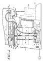
- Figure 2 is a view similar to Figure 1 showing the dispensing system in operation during a brew cycle;
- Figures 3A and 3B are enlarged views of the circled areas in Figures 1 and 2;
- Figure 4 is an enlarged view diagrammatically depicting air being vented from and heated liquid flowing into the metering chamber as the baffle is raised at the conclusion of a brew cycle; and
- Figure 5 is a view similar to Figure 4 diagrammatically depicting water circulation 25 after the metering chamber has been refilled.
- With reference initially to Figure 1, a
single serve brewer 10 includes ahousing 12 enclosing aliquid storage tank 14. The tank has alower metering chamber 16 formed by a reduced diameter cup-shaped bottom 18 integrally joined to the larger diameter tank side wall at a circular sealing surface defining aseat 20. - A fixed internal structure includes a
horizontal platform 22 andstruts 24 supporting a vertically disposed sleeve bearing 26 aligned centrally with respect to thetank 14 and its cup-shaped bottom 18. - A vertically
reciprocal shaft 28 extends through the sleeve bearing 26. The shaft carries acircular baffle 30 at its lower end, and acircular plate 32 disposed beneath theplatform 22. With additional reference to Figure 3A, it will be seen that the lower surface of thebaffle 30 is configured with a downwardly protruding centralconical area 30a surrounded by a flat annularhorizontal shelf 30b. A resilientcompressible gasket 33 is secured to the shelf at a location overlying theseat 20. - An
arm 34 is pivotally mounted on abracket 36 carried by theplatform 22.Arm 34 is connected to theshaft 28 by apin 38. Acoiled spring 40 surrounds thepin 38 between thearm 34 and the upper surface ofplatform 22, and aninflatable bladder 42 is positioned between the bottom surface of theplatform 22 and theplate 32. - The distal end of
arm 34 extends into abrewing chamber 44 designed to accept a single servebeverage filter cartridge 46 of the type described, for example, in copending patent application Serial No. 09/782,622 filed 02/13/2001, the description of which is herein incorporated by reference in its entirety. - An
air pump 48 onplatform 22 is connected to thebladder 42, and is also connected via aflexible hose 50 to aport 52 in thebaffle 30. Ametering tube 54 extends through thebaffle 30 into thechamber 16. Themetering tube 54 is connected via a secondflexible hose 56 to a dependingtubular probe 58 carried by thearm 34. A secondtubular probe 60 underlies thecartridge 46 and opens downwardly above anexterior shelf 62 configured and dimensioned to support acup 64 or other like receptacle. - The
tank 14 stores a supply ofliquid 66 heated by anelectrical heating element 68 underlying the cup-shaped bottom 18. - During a brewing cycle, a control system including appropriate valves and circuitry (not shown) operates the
air pump 48 to pneumatically effect the following sequence: - a) As shown in Fig. 2, the
bladder 42 is inflated, pushingshaft 28 and baffle 30 downwardly, until thegasket 33 is pressed against theseat 20 to seal off the liquid in themetering chamber 16 from the remainder of thetank 14. Downward movement of theshaft 28 also produces downward pivotal movement ofarm 34 against the resistance of thespring 40, which in turn results in the lid and bottom of thecartridge 46 inbrewing chamber 44 being pierced respectively byprobes - b) Compressed air is then fed into the
metering chamber 16 viahose 50, causing a metered amount of liquid to be expelled and fed to thecartridge 46 viahose 56 and thetubular probe 58. The resulting heated liquid combines with a beverage medium in the cartridge to produce brewed beverage that exits via theprobe 60 and is received in theunderlying cup 64. - c) At the conclusion of the brew cycle, the
pump 46 is deactivated and the system is vented and returned to the condition shown in Figure 1. Thebladder 42 is collapsed under the return force ofspring 40 causing an upward displacement of theshaft 28. Thebaffle 30 is thus raised above theseat 20, allowing air in thechamber 16 to be displaced by liquid in thetank 14. The return force of thespring 40 also pivotsarm 34 upwardly, which in turn removes theprobe 58 from thecartridge 46. - The
spent cartridge 46 may then be removed from the brewing chamber, readying the system for the next cycle. - With reference to Figure 4, it will be seen that the
conical area 30a has an angle of taper α between about 5 to 20°, with the preferred range being between about 8 to 12°. - With this arrangement, as shown in Figure 4, upon elevation of the baffle at the conclusion of a brew cycle, the conical
central area 30a assists in uniformly distributing the escaping air (diagrammatically depicted by broken arrows) to and around the entire periphery of the baffle. The escaping air is displaced by a counterflow of water (diagrammatically depicted by solid arrows) which enters the metering chamber around the entire periphery of the baffle. - As shown in Figure 5, when the
baffle 30 is in its fully elevated position, it coacts with theseat 20 to define a gap "x" which measures between about 2 to 10% of the baffle diameter "D", and preferably between about 3 to 5% of the baffle diameter. The baffle induces a thermal stratification between themetering chamber 16 and the remainder of the tank. As indicated diagrammatically by the solid arrows, the gap "x" serves to control convective flow and heat transfer between the metering chamber and the remainder of the tank, while encouraging a recirculating convective flow within the metering chamber. This insures both a rapid heating of water received in the metering chamber and a more gradual and uniform heating of water in the remainder of the tank. - Various modifications may be made to the embodiment herein disclosed. For example, the
shaft 28 may be vertically reciprocated by other means, e.g., a motor-driven gear drive, or manual operation of thearm 34. Themetering chamber 16 andseat 20 may be formed on a separate cup-shaped insert received in the tank, rather than being formed integrally with the tank. - Internal rather than external heating elements could be employed to heat the liquid in the storage tank. Other tank shapes with for example square or rectangular cross sections could employ comparably shaped baffles. Multiple air pumps could be employed to inflate the
bladder 42 and to pressurize themetering chamber 16. - It is our intention to cover these and any other changes and modifications that do not depart from the scope of the invention as defined by the appended claims.
Claims (17)
- A beverage brewer comprising;a storage tank (14) adapted to contain a supply of liquid;a metering chamber (16) structured and arranged to be filled with a metered amount of said liquid received from said storage tank (14) via an inlet in communication therewith;a brewing chamber (44) structured and arranged to receive a beverage filter cartridge (46) containing a beverage medium;a baffle (30) movably arranged in said storage tank (14);actuating means (42) operable in a first mode to shift said baffle (30) from an open position accommodating liquid flow between said storage tank (14) and said metering chamber (16) via said inlet, to a closed position preventing said flow and isolating said metering chamber (16) from said storage tank (14); andconnecting means (56) for establishing a connection between said metering chamber (46) and said brewing chamber (44); characterised bydispensing means (48) operable during a brewing cycle to pneumatically pressurize and deliver liquid from the thus isolated metering chamber (16) via said connecting means (56) to said brewing chamber (44) for combination with the beverage medium contained in said filter cartridge (46), said actuating means (42) being operable in a second mode at the conclusion of said brewing cycle to shift said baffle to said open position, thereby allowing said metering chamber (16) to be refilled with liquid received from said storage tank (14) via said inlet.
- The beverage brewer of claim 1 wherein said storage tank has a cylindrical side wall, and said metering chamber is formed as a reduced diameter cup-shaped bottom (18) of said storage tank.
- The beverage brewer of claim 2 wherein said cup-shaped bottom is joined to said cylindrical side wall by a circular sealing surface (20) surrounding said inlet.
- The beverage brewer of claim 1 wherein said actuating means is pneumatically driven in said first mode.
- The beverage brewer of claim 1 or claim 4 wherein said actuating means is resiliently driven in said second mode.
- The beverage brewer of claim 1 wherein said connecting means communicates with said metering chamber via a port (54) extending through said baffle.
- The beverage brewer of claim 1 wherein said baffle is carried on a shaft (28) supported for vertical reciprocal movement between said open and closed positions.
- The beverage brewer of claim 7 further comprising a horizontal platform (22) overlying and fixed with respect to said storage tank, said vertical shaft extending through and being vertically reciprocal with respect to said platform, and a plate (32) secured to said shaft beneath said platform, said actuating means including a bladder interposed between said platform and said plate, said bladder being pneumatically inflatable in said first mode to axially lower said shaft with an accompanying shifting of said baffle from said open to said closed position.
- The beverage brewer of claim 8 further comprising an arm (34) arranged above said platform, said arm being pivotally supported on said platform and having a distal end extending into said brewing chamber, a tubular inlet probe (58) carried by the distal end of said arm, and means for connecting (38) said arm to said shaft, whereby an axial lowering of said shaft is accompanied by a pivotal lowering of the distal end of said arm, causing said inlet probe to pierce a beverage filter cartridge received in said brewing chamber, the said dispensing means being operable via said probe to deliver liquid to the interior of the thus pierced beverage cartridge.
- The beverage brewer of claim 1 wherein a circular lower surface of said baffle includes a central downwardly protruding conical area (30a) surrounded by a horizontal annular ledge (30b).
- The beverage brewer of claim 10 wherein said conical area has an angle of taper of between 5 - 20°.
- The beverage brewer of claim 10 wherein said conical area has an angle of taper of between about 8 - 12°.
- The beverage brewer of claim 10 wherein a circular seat (20) is defined at a juncture between said storage tank and said metering chamber, and a gasket (33) is provided on said annular ledge, said gasket being structured and dimensioned to coact in a sealing relationship with said seat when said baffle is in said closed position.
- The beverage brewer of claim 13 wherein said baffle is in said open position, said gasket is spaced from said circular seat by a gap measuring between about 2 - 10% of the diameter of said baffle.
- The beverage brewer of claim 14 wherein said gap measures between about 3 - 5% of the diameter of said baffle.
- The beverage brewer of claim 1, further comprising:resiliently actuated means (40) operable in a second mode at the conclusion of said brewing cycle to shift said baffle to said open position, thereby allowing said metering chamber to be refilled with liquid received from said storage tank via said inlet.
- The beverage brewer of claim 1, wherein said storage tank (14) and said metering chamber (16) coact at a juncture therebetween to define a seat (20); said baffle has a downwardly facing area (30a) surrounded by a sealing gasket (33); and said actuating means (42) urges said gasket against said seat to prevent said flow and to isolate said metering chamber from said storage tank.
Applications Claiming Priority (7)
| Application Number | Priority Date | Filing Date | Title |
|---|---|---|---|
| US113187 | 1980-01-18 | ||
| US28195401P | 2001-04-06 | 2001-04-06 | |
| US281954P | 2001-04-06 | ||
| US28440301P | 2001-04-17 | 2001-04-17 | |
| US284403P | 2001-04-17 | ||
| US10/113,187 US6666130B2 (en) | 2001-04-06 | 2002-04-01 | Baffle operated liquid heating and dispensing system for a single serve beverage brewer |
| PCT/US2002/010636 WO2002080743A2 (en) | 2001-04-06 | 2002-04-04 | Baffle operated liquid heating and dispensing system for a single serve beverage brewer |
Publications (2)
| Publication Number | Publication Date |
|---|---|
| EP1372444A2 EP1372444A2 (en) | 2004-01-02 |
| EP1372444B1 true EP1372444B1 (en) | 2006-06-21 |
Family
ID=27381287
Family Applications (1)
| Application Number | Title | Priority Date | Filing Date |
|---|---|---|---|
| EP02717771A Expired - Lifetime EP1372444B1 (en) | 2001-04-06 | 2002-04-04 | Baffle operated liquid heating and dispensing system for a single serve beverage brewer |
Country Status (9)
| Country | Link |
|---|---|
| US (1) | US6666130B2 (en) |
| EP (1) | EP1372444B1 (en) |
| JP (1) | JP3883963B2 (en) |
| KR (1) | KR20030088058A (en) |
| AT (1) | ATE330520T1 (en) |
| AU (1) | AU2002248753A1 (en) |
| CA (1) | CA2442983C (en) |
| DE (1) | DE60212593T2 (en) |
| WO (1) | WO2002080743A2 (en) |
Families Citing this family (76)
| Publication number | Priority date | Publication date | Assignee | Title |
|---|---|---|---|---|
| US7770512B2 (en) | 2002-05-01 | 2010-08-10 | Courtesy Products, Llc | Disposable brew basket for electric coffee maker |
| US7081263B2 (en) | 2002-05-01 | 2006-07-25 | Courtesy Products, Llc | Disposable brew basket for electric coffee maker |
| US7640843B2 (en) * | 2003-01-24 | 2010-01-05 | Kraft Foods R & D, Inc. | Cartridge and method for the preparation of beverages |
| US7281467B2 (en) * | 2003-10-22 | 2007-10-16 | Household Technology Group Llc | Fluid delivery system for generating pressurized hot water pulses |
| PL1686879T3 (en) * | 2003-11-22 | 2008-03-31 | Nestec Sa | Mobile or portable apparatus with pressurized gas supply for preparing beverages or similar products |
| US7523695B2 (en) * | 2003-12-12 | 2009-04-28 | Keurig, Incorporated | System for dispensing metered volumes of heated water to the brew chamber of a single serve beverage brewer |
| US20050205601A1 (en) * | 2004-03-01 | 2005-09-22 | Jon Taylor | Water dispensing systrem with vaccum-filled metering chamber |
| PT1768530E (en) * | 2004-07-09 | 2010-08-27 | Nestec Sa | Apparatus with pressurised gas supply for preparing beverages |
| TWI281855B (en) * | 2005-04-13 | 2007-06-01 | Wu Jian Wen | Coffee flushing and filtering method by using high-pressure air |
| US7819284B2 (en) * | 2006-02-09 | 2010-10-26 | Robert Hale | Method and apparatus for dispensing liquid in a beverage brewing machine |
| WO2008124851A1 (en) | 2007-04-05 | 2008-10-16 | Carl Santoiemmo | Select serving and flavored sparkling beverage maker |
| US20110020508A1 (en) | 2007-04-05 | 2011-01-27 | Rising Phoenix Co. | Select Serving and Flavored Sparkling Beverage Maker |
| US8677888B2 (en) | 2007-04-05 | 2014-03-25 | Primo Products, LLC | Select serving and flavored sparkling beverage maker |
| GB2449420B (en) * | 2007-05-18 | 2009-10-21 | Kraft Foods R & D Inc | Improvments in or relating to beverage preparation machines |
| GB2449422B (en) | 2007-05-18 | 2009-09-16 | Kraft Foods R & D Inc | Improvements in or relating to beverage preparation machines |
| GB2449421B (en) | 2007-05-18 | 2009-09-09 | Kraft Foods R & D Inc | Improvements in or relating to beverage preparation machines |
| US11832755B2 (en) * | 2007-07-13 | 2023-12-05 | Adrian Rivera | Brewing material container for a beverage brewer |
| US10722066B2 (en) * | 2010-12-04 | 2020-07-28 | Adrian Rivera | Windowed single serving brewing material holder |
| GB0725235D0 (en) * | 2007-12-24 | 2008-02-06 | Strix Ltd | Liquid heating apparatus |
| JP5320407B2 (en) * | 2007-12-24 | 2013-10-23 | ストリックス リミテッド | Liquid heating device |
| US20110215085A1 (en) * | 2008-10-07 | 2011-09-08 | Strix Limited | Liquid heating devices |
| DE102008043604A1 (en) * | 2008-11-10 | 2010-05-12 | Bühler AG | Casting machine and casting machine valve |
| US20100313765A1 (en) * | 2009-06-12 | 2010-12-16 | Robert Hale | Water heating system for hot beverage dispensing machine |
| CA2765134C (en) | 2009-06-17 | 2019-03-12 | Sara Lee/De B.V. | System, method and capsule for preparing a beverage |
| RU2015140837A (en) | 2009-06-17 | 2018-12-26 | Конинклейке Дауве Егбертс Б.В. | SYSTEM, METHOD AND CAPSULE FOR PREPARING A SET NUMBER OF DRINKS |
| JP5735959B2 (en) | 2009-06-17 | 2015-06-17 | コーニンクラケ ダウ エグバート ビー.ブイ. | System, apparatus and method for making a beverage |
| DK2361206T3 (en) | 2009-06-17 | 2019-10-07 | Douwe Egberts Bv | CAPS FOR CONTAINING BEVERAGES INGREDIENTS |
| DK2442695T3 (en) | 2009-06-17 | 2015-07-06 | Koninkl Douwe Egberts Bv | Capsule and system for producing a beverage comprising a soluble substance |
| RU2534058C2 (en) | 2009-06-17 | 2014-11-27 | Конинклейке Дауве Егбертс Б.В., Nl | System, method and capsule for beverage preparation |
| US8919241B2 (en) * | 2009-08-18 | 2014-12-30 | Robert Hale | Beverage machine brewing chamber and extraction member for a beverage dispensing machine |
| US9527661B2 (en) * | 2009-09-29 | 2016-12-27 | Lbp Manufacturing Llc | Disposable single use beverage package |
| US9108794B2 (en) | 2009-09-29 | 2015-08-18 | Lbp Manufacturing, Inc. | Disposable single use beverage package |
| US9060645B2 (en) * | 2010-02-02 | 2015-06-23 | Uniterra, Inc. | Beverage brewing device and method |
| US8495949B2 (en) | 2010-02-12 | 2013-07-30 | Keurig, Incorporated | Apparatus for beverage formation with automated water delivery to heating tank |
| US10071851B2 (en) | 2010-07-12 | 2018-09-11 | Robert Bao Vu | Apparatus and products for producing beverages, and methods for making and using same |
| DK3521209T3 (en) * | 2010-07-22 | 2020-04-27 | K Fee System Gmbh | BOTTLE COOKING COVER |
| USD649390S1 (en) | 2010-09-02 | 2011-11-29 | Primo Products, LLC | Beverage maker |
| CN102440686B (en) * | 2010-10-09 | 2016-06-22 | 皇家飞利浦电子股份有限公司 | A kind of for carrying the method for solvent, system and using the equipment of this system |
| US8927037B2 (en) | 2011-02-08 | 2015-01-06 | Kevin B. Kihnke | Disposable cartridge for brewed beverages |
| USD694620S1 (en) | 2011-03-08 | 2013-12-03 | Kraft Foods R&D, Inc. | Beverage cartridge |
| GB2488799A (en) | 2011-03-08 | 2012-09-12 | Kraft Foods R & D Inc | Drinks Pod without Piercing of Outer Shell |
| US9114902B2 (en) | 2011-03-22 | 2015-08-25 | Polyone Designed Structures And Solutions Llc | Methods and systems for use in forming an article from a multi-layer sheet structure |
| GB2489409B (en) | 2011-03-23 | 2013-05-15 | Kraft Foods R & D Inc | A capsule and a system for, and a method of, preparing a beverage |
| USD675091S1 (en) | 2011-05-25 | 2013-01-29 | Lbp Manufacturing, Inc. | Disposable cup with wave rib |
| USD675089S1 (en) | 2011-05-25 | 2013-01-29 | Lbp Manufacturing, Inc. | Disposable cup with curved rib |
| USD675090S1 (en) | 2011-05-25 | 2013-01-29 | Lbp Manufacturing, Inc. | Disposable cup with straight rib |
| US9452879B2 (en) | 2011-07-26 | 2016-09-27 | Lbp Manufacturing Llc | Sealed beverage basket and method of making |
| US9161654B2 (en) | 2012-03-09 | 2015-10-20 | Primo Products Llc | Select serving and flavored sparkling beverage maker system |
| CA2876920C (en) | 2012-06-22 | 2016-08-23 | Touch Coffee & Beverages, Llc | Beverage brewing system |
| USD697797S1 (en) | 2012-09-12 | 2014-01-21 | Kraft Foods R&D, Inc. | Beverage cartridge |
| US9192260B2 (en) | 2013-02-23 | 2015-11-24 | Dov Z Glucksman | Apparatus and method for infusing hot beverages |
| CA2905217C (en) | 2013-04-03 | 2016-11-08 | 2266170 Ontario Inc. | Capsule machine and components |
| US10687655B2 (en) | 2014-02-25 | 2020-06-23 | Newco Enterprises, Inc. | Beverage brewing device for brewing and removal of different sized beverage capsules |
| US9788682B2 (en) | 2014-02-25 | 2017-10-17 | Newco Enterprises, Inc. | Beverage brewing device for automatically brewing and dispensing single cup quantities of beverage through a vending machine with minimal manual participation |
| US11272804B2 (en) | 2014-02-25 | 2022-03-15 | Newco Enterprises, Inc. | Beverage brewing device for brewing and removal of different sized flavored beverage packets (POD) |
| US10028615B2 (en) | 2014-06-17 | 2018-07-24 | Sharkninja Operating Llc | Method of brewing coffee |
| US11051649B2 (en) | 2014-06-17 | 2021-07-06 | Sharkninja Operating Llc | Automatic coffee maker and method of preparing a brewed beverage |
| JP6696914B2 (en) * | 2014-06-25 | 2020-05-20 | ソシエテ・デ・プロデュイ・ネスレ・エス・アー | Disposable whipping device |
| US10450131B2 (en) | 2014-10-01 | 2019-10-22 | Kraft Foods Group Brands Llc | Coffee pod |
| US9585513B2 (en) * | 2015-02-04 | 2017-03-07 | Hamilton Beach Brands, Inc. | Pump operated beverage maker |
| US10314320B2 (en) | 2015-03-20 | 2019-06-11 | Meltz, LLC | Systems for controlled liquid food or beverage product creation |
| US9487348B2 (en) | 2015-03-20 | 2016-11-08 | Meltz, LLC | Systems for and methods of providing support for displaceable frozen contents in beverage and food receptacles |
| US9346611B1 (en) | 2015-03-20 | 2016-05-24 | Meltz, LLC | Apparatus and processes for creating a consumable liquid food or beverage product from frozen contents |
| US10111554B2 (en) | 2015-03-20 | 2018-10-30 | Meltz, LLC | Systems for and methods of controlled liquid food or beverage product creation |
| US9402501B1 (en) | 2015-07-27 | 2016-08-02 | Solofill, Llc | Adjustable tamper coffee apparatus, brewing machine utilizing such apparatus, and methods for making coffee |
| CA3041722A1 (en) | 2016-11-09 | 2018-05-17 | Pepsico, Inc. | Carbonated beverage makers, methods, and systems |
| WO2018200922A1 (en) | 2017-04-27 | 2018-11-01 | Meltz, LLC | Method for centrifugal extraction and apparatus suitable for carrying out this method |
| US10358275B1 (en) | 2017-06-16 | 2019-07-23 | Plitek, L.L.C. | Pressure relief valve with a plural-part dry strap |
| EP3482659B1 (en) | 2017-11-14 | 2020-05-27 | BSH Hausgeräte GmbH | Coffee machine drainage channel |
| US11589703B1 (en) | 2019-05-08 | 2023-02-28 | Microtrace, LLC. | Spectral signature systems that use encoded image data and encoded spectral signature data |
| US11724849B2 (en) | 2019-06-07 | 2023-08-15 | Cometeer, Inc. | Packaging and method for single serve beverage product |
| US11553814B2 (en) | 2019-08-28 | 2023-01-17 | Ii-Vi Delaware, Inc. | Non-electric powered, off-grid, beverage brewer |
| US11352183B2 (en) | 2020-03-05 | 2022-06-07 | Plitek, L.L.C. | Pressure relief valve with wetting fluid reservoirs |
| EP3881730B1 (en) | 2020-03-17 | 2023-03-01 | BSH Hausgeräte GmbH | Coffee machine ventilation channel |
| US11805934B1 (en) * | 2020-10-21 | 2023-11-07 | Adrian Rivera | Brewing material lid and container for a beverage brewer |
| IL301230A (en) | 2023-03-08 | 2024-10-01 | Hanan Ben David | Capsule for making a drink |
Family Cites Families (6)
| Publication number | Priority date | Publication date | Assignee | Title |
|---|---|---|---|---|
| DE3436984A1 (en) | 1984-10-09 | 1986-04-17 | Erich H. Dipl.-Ing. 4950 Minden Woltermann | MACHINE FOR PREPARING HOT DRINKS WITH DOSED LIQUID REMOVAL |
| CA1269690A (en) | 1989-03-14 | 1990-05-29 | Peter Klein | Electrical apparatus useful to prepare a hot beverage |
| JPH05161552A (en) * | 1991-12-11 | 1993-06-29 | Kazuo Enomoto | Coffee maker |
| JPH11178717A (en) | 1997-12-11 | 1999-07-06 | Master Foods Ltd | Beverage supply device |
| US6082247A (en) * | 1999-01-19 | 2000-07-04 | Keurig, Inc. | Apparatus for consecutively dispensing an equal volume of liquid |
| US6645537B2 (en) | 2000-02-18 | 2003-11-11 | Keurig, Incorporated | Beverage filter cartridge |
-
2002
- 2002-04-01 US US10/113,187 patent/US6666130B2/en not_active Expired - Lifetime
- 2002-04-04 EP EP02717771A patent/EP1372444B1/en not_active Expired - Lifetime
- 2002-04-04 DE DE60212593T patent/DE60212593T2/en not_active Expired - Lifetime
- 2002-04-04 CA CA002442983A patent/CA2442983C/en not_active Expired - Fee Related
- 2002-04-04 WO PCT/US2002/010636 patent/WO2002080743A2/en not_active Ceased
- 2002-04-04 AU AU2002248753A patent/AU2002248753A1/en not_active Abandoned
- 2002-04-04 AT AT02717771T patent/ATE330520T1/en not_active IP Right Cessation
- 2002-04-04 JP JP2002578786A patent/JP3883963B2/en not_active Expired - Fee Related
- 2002-04-04 KR KR10-2003-7013060A patent/KR20030088058A/en not_active Ceased
Also Published As
| Publication number | Publication date |
|---|---|
| AU2002248753A1 (en) | 2002-10-21 |
| EP1372444A2 (en) | 2004-01-02 |
| CA2442983C (en) | 2007-07-10 |
| ATE330520T1 (en) | 2006-07-15 |
| DE60212593T2 (en) | 2007-05-24 |
| KR20030088058A (en) | 2003-11-15 |
| WO2002080743A3 (en) | 2003-01-09 |
| WO2002080743A2 (en) | 2002-10-17 |
| DE60212593D1 (en) | 2006-08-03 |
| JP2004538044A (en) | 2004-12-24 |
| JP3883963B2 (en) | 2007-02-21 |
| US6666130B2 (en) | 2003-12-23 |
| US20020144602A1 (en) | 2002-10-10 |
| CA2442983A1 (en) | 2002-10-17 |
Similar Documents
| Publication | Publication Date | Title |
|---|---|---|
| CA2442983C (en) | Baffle operated liquid heating and dispensing system for a single serve beverage brewer | |
| CN101808554B (en) | Hot beverage brewing apparatus | |
| KR101976851B1 (en) | Method and apparatus for beverage formation with automated water delivery to heating tank | |
| EP1924178B1 (en) | Drain for beverage forming machine | |
| US20220079375A1 (en) | System for heating and frothing a beverage, a device for heating and frothing a beverage suitable for being used in such a system, a froth wand suitable for being used in such a system and a method of preparing a beverage using such a system | |
| US9247846B2 (en) | Hot beverage brewing apparatus | |
| US20130247772A1 (en) | Beverage machine with reliable user-indicator | |
| US20020144603A1 (en) | Two step puncturing and venting of single serve filter cartridge in a beverage brewer | |
| US20090120299A1 (en) | Line Pressure Brewer | |
| WO2015126684A1 (en) | Apparatus and method for infusing hot beverages | |
| JP2011519297A (en) | Espresso coffee machine with pre-brewing device | |
| PL247304B1 (en) | Device for preparing freshly brewed herbal infusion, especially tea, replaceable cassette and method for preparing freshly brewed herbal infusion | |
| HK1119037B (en) | Drain for beverage forming machine | |
| RU99103645A (en) | DEVICE FOR BREWING ONE CUP OF DRINK AND CASING HOUSING FOR THIS DEVICE |
Legal Events
| Date | Code | Title | Description |
|---|---|---|---|
| PUAI | Public reference made under article 153(3) epc to a published international application that has entered the european phase |
Free format text: ORIGINAL CODE: 0009012 |
|
| 17P | Request for examination filed |
Effective date: 20031020 |
|
| AK | Designated contracting states |
Kind code of ref document: A2 Designated state(s): AT BE CH CY DE DK ES FI FR GB GR IE IT LI LU MC NL PT SE TR |
|
| AX | Request for extension of the european patent |
Extension state: AL LT LV MK RO SI |
|
| RIN1 | Information on inventor provided before grant (corrected) |
Inventor name: TAYLOR, JON Inventor name: LIPMAN, JASON, F. |
|
| 17Q | First examination report despatched |
Effective date: 20050228 |
|
| GRAP | Despatch of communication of intention to grant a patent |
Free format text: ORIGINAL CODE: EPIDOSNIGR1 |
|
| GRAS | Grant fee paid |
Free format text: ORIGINAL CODE: EPIDOSNIGR3 |
|
| GRAA | (expected) grant |
Free format text: ORIGINAL CODE: 0009210 |
|
| AK | Designated contracting states |
Kind code of ref document: B1 Designated state(s): AT BE CH CY DE DK ES FI FR GB GR IE IT LI LU MC NL PT SE TR |
|
| PG25 | Lapsed in a contracting state [announced via postgrant information from national office to epo] |
Ref country code: IT Free format text: LAPSE BECAUSE OF FAILURE TO SUBMIT A TRANSLATION OF THE DESCRIPTION OR TO PAY THE FEE WITHIN THE PRESCRIBED TIME-LIMIT;WARNING: LAPSES OF ITALIAN PATENTS WITH EFFECTIVE DATE BEFORE 2007 MAY HAVE OCCURRED AT ANY TIME BEFORE 2007. THE CORRECT EFFECTIVE DATE MAY BE DIFFERENT FROM THE ONE RECORDED. Effective date: 20060621 Ref country code: LI Free format text: LAPSE BECAUSE OF FAILURE TO SUBMIT A TRANSLATION OF THE DESCRIPTION OR TO PAY THE FEE WITHIN THE PRESCRIBED TIME-LIMIT Effective date: 20060621 Ref country code: FI Free format text: LAPSE BECAUSE OF FAILURE TO SUBMIT A TRANSLATION OF THE DESCRIPTION OR TO PAY THE FEE WITHIN THE PRESCRIBED TIME-LIMIT Effective date: 20060621 Ref country code: AT Free format text: LAPSE BECAUSE OF FAILURE TO SUBMIT A TRANSLATION OF THE DESCRIPTION OR TO PAY THE FEE WITHIN THE PRESCRIBED TIME-LIMIT Effective date: 20060621 Ref country code: CH Free format text: LAPSE BECAUSE OF FAILURE TO SUBMIT A TRANSLATION OF THE DESCRIPTION OR TO PAY THE FEE WITHIN THE PRESCRIBED TIME-LIMIT Effective date: 20060621 Ref country code: NL Free format text: LAPSE BECAUSE OF FAILURE TO SUBMIT A TRANSLATION OF THE DESCRIPTION OR TO PAY THE FEE WITHIN THE PRESCRIBED TIME-LIMIT Effective date: 20060621 Ref country code: BE Free format text: LAPSE BECAUSE OF FAILURE TO SUBMIT A TRANSLATION OF THE DESCRIPTION OR TO PAY THE FEE WITHIN THE PRESCRIBED TIME-LIMIT Effective date: 20060621 |
|
| REG | Reference to a national code |
Ref country code: GB Ref legal event code: FG4D |
|
| REG | Reference to a national code |
Ref country code: CH Ref legal event code: EP |
|
| REG | Reference to a national code |
Ref country code: IE Ref legal event code: FG4D |
|
| REF | Corresponds to: |
Ref document number: 60212593 Country of ref document: DE Date of ref document: 20060803 Kind code of ref document: P |
|
| PG25 | Lapsed in a contracting state [announced via postgrant information from national office to epo] |
Ref country code: DK Free format text: LAPSE BECAUSE OF FAILURE TO SUBMIT A TRANSLATION OF THE DESCRIPTION OR TO PAY THE FEE WITHIN THE PRESCRIBED TIME-LIMIT Effective date: 20060921 Ref country code: SE Free format text: LAPSE BECAUSE OF FAILURE TO SUBMIT A TRANSLATION OF THE DESCRIPTION OR TO PAY THE FEE WITHIN THE PRESCRIBED TIME-LIMIT Effective date: 20060921 |
|
| PG25 | Lapsed in a contracting state [announced via postgrant information from national office to epo] |
Ref country code: ES Free format text: LAPSE BECAUSE OF FAILURE TO SUBMIT A TRANSLATION OF THE DESCRIPTION OR TO PAY THE FEE WITHIN THE PRESCRIBED TIME-LIMIT Effective date: 20061002 |
|
| PG25 | Lapsed in a contracting state [announced via postgrant information from national office to epo] |
Ref country code: PT Free format text: LAPSE BECAUSE OF FAILURE TO SUBMIT A TRANSLATION OF THE DESCRIPTION OR TO PAY THE FEE WITHIN THE PRESCRIBED TIME-LIMIT Effective date: 20061121 |
|
| NLV1 | Nl: lapsed or annulled due to failure to fulfill the requirements of art. 29p and 29m of the patents act | ||
| REG | Reference to a national code |
Ref country code: CH Ref legal event code: PL |
|
| ET | Fr: translation filed | ||
| PLBE | No opposition filed within time limit |
Free format text: ORIGINAL CODE: 0009261 |
|
| STAA | Information on the status of an ep patent application or granted ep patent |
Free format text: STATUS: NO OPPOSITION FILED WITHIN TIME LIMIT |
|
| 26N | No opposition filed |
Effective date: 20070322 |
|
| PG25 | Lapsed in a contracting state [announced via postgrant information from national office to epo] |
Ref country code: GR Free format text: LAPSE BECAUSE OF FAILURE TO SUBMIT A TRANSLATION OF THE DESCRIPTION OR TO PAY THE FEE WITHIN THE PRESCRIBED TIME-LIMIT Effective date: 20060922 |
|
| PG25 | Lapsed in a contracting state [announced via postgrant information from national office to epo] |
Ref country code: IE Free format text: LAPSE BECAUSE OF NON-PAYMENT OF DUE FEES Effective date: 20070404 |
|
| PG25 | Lapsed in a contracting state [announced via postgrant information from national office to epo] |
Ref country code: MC Free format text: LAPSE BECAUSE OF NON-PAYMENT OF DUE FEES Effective date: 20070430 |
|
| PG25 | Lapsed in a contracting state [announced via postgrant information from national office to epo] |
Ref country code: CY Free format text: LAPSE BECAUSE OF FAILURE TO SUBMIT A TRANSLATION OF THE DESCRIPTION OR TO PAY THE FEE WITHIN THE PRESCRIBED TIME-LIMIT Effective date: 20060621 Ref country code: LU Free format text: LAPSE BECAUSE OF NON-PAYMENT OF DUE FEES Effective date: 20070404 |
|
| PG25 | Lapsed in a contracting state [announced via postgrant information from national office to epo] |
Ref country code: TR Free format text: LAPSE BECAUSE OF FAILURE TO SUBMIT A TRANSLATION OF THE DESCRIPTION OR TO PAY THE FEE WITHIN THE PRESCRIBED TIME-LIMIT Effective date: 20060621 |
|
| REG | Reference to a national code |
Ref country code: DE Ref legal event code: R082 Ref document number: 60212593 Country of ref document: DE Representative=s name: SCHUMACHER & WILLSAU PATENTANWALTSGESELLSCHAFT, DE |
|
| REG | Reference to a national code |
Ref country code: GB Ref legal event code: 732E Free format text: REGISTERED BETWEEN 20140918 AND 20140924 |
|
| REG | Reference to a national code |
Ref country code: DE Ref legal event code: R082 Ref document number: 60212593 Country of ref document: DE Representative=s name: SCHUMACHER & WILLSAU PATENTANWALTSGESELLSCHAFT, DE |
|
| REG | Reference to a national code |
Ref country code: FR Ref legal event code: CA Effective date: 20150220 Ref country code: FR Ref legal event code: CD Owner name: KEURIG GREEN MOUNTAIN, INC., US Effective date: 20150220 Ref country code: FR Ref legal event code: TP Owner name: KEURIG GREEN MOUNTAIN, INC., US Effective date: 20150220 |
|
| REG | Reference to a national code |
Ref country code: DE Ref legal event code: R082 Ref document number: 60212593 Country of ref document: DE Representative=s name: SCHUMACHER & WILLSAU PATENTANWALTSGESELLSCHAFT, DE Effective date: 20130127 Ref country code: DE Ref legal event code: R081 Ref document number: 60212593 Country of ref document: DE Owner name: KEURIG GREEN MOUNTAIN, INC. (N. D. GES. D. STA, US Free format text: FORMER OWNER: KEURIG, INC., WAKEFIELD, MASS., US Effective date: 20150219 Ref country code: DE Ref legal event code: R082 Ref document number: 60212593 Country of ref document: DE Representative=s name: SCHUMACHER & WILLSAU PATENTANWALTSGESELLSCHAFT, DE Effective date: 20150219 |
|
| REG | Reference to a national code |
Ref country code: FR Ref legal event code: PLFP Year of fee payment: 14 |
|
| REG | Reference to a national code |
Ref country code: FR Ref legal event code: PLFP Year of fee payment: 15 |
|
| REG | Reference to a national code |
Ref country code: FR Ref legal event code: PLFP Year of fee payment: 16 |
|
| REG | Reference to a national code |
Ref country code: FR Ref legal event code: PLFP Year of fee payment: 17 |
|
| PGFP | Annual fee paid to national office [announced via postgrant information from national office to epo] |
Ref country code: DE Payment date: 20180427 Year of fee payment: 17 |
|
| PGFP | Annual fee paid to national office [announced via postgrant information from national office to epo] |
Ref country code: FR Payment date: 20180425 Year of fee payment: 17 Ref country code: IT Payment date: 20180423 Year of fee payment: 17 |
|
| PGFP | Annual fee paid to national office [announced via postgrant information from national office to epo] |
Ref country code: GB Payment date: 20180427 Year of fee payment: 17 |
|
| REG | Reference to a national code |
Ref country code: DE Ref legal event code: R119 Ref document number: 60212593 Country of ref document: DE |
|
| GBPC | Gb: european patent ceased through non-payment of renewal fee |
Effective date: 20190404 |
|
| PG25 | Lapsed in a contracting state [announced via postgrant information from national office to epo] |
Ref country code: GB Free format text: LAPSE BECAUSE OF NON-PAYMENT OF DUE FEES Effective date: 20190404 Ref country code: DE Free format text: LAPSE BECAUSE OF NON-PAYMENT OF DUE FEES Effective date: 20191101 |
|
| PG25 | Lapsed in a contracting state [announced via postgrant information from national office to epo] |
Ref country code: FR Free format text: LAPSE BECAUSE OF NON-PAYMENT OF DUE FEES Effective date: 20190430 |
|
| PG25 | Lapsed in a contracting state [announced via postgrant information from national office to epo] |
Ref country code: IT Free format text: LAPSE BECAUSE OF NON-PAYMENT OF DUE FEES Effective date: 20190404 |