EP1372344A1 - Image pickup apparatus, white balance control method and white balance control program - Google Patents
Image pickup apparatus, white balance control method and white balance control program Download PDFInfo
- Publication number
- EP1372344A1 EP1372344A1 EP03013570A EP03013570A EP1372344A1 EP 1372344 A1 EP1372344 A1 EP 1372344A1 EP 03013570 A EP03013570 A EP 03013570A EP 03013570 A EP03013570 A EP 03013570A EP 1372344 A1 EP1372344 A1 EP 1372344A1
- Authority
- EP
- European Patent Office
- Prior art keywords
- gain
- image pickup
- image
- amplifying
- gains
- Prior art date
- Legal status (The legal status is an assumption and is not a legal conclusion. Google has not performed a legal analysis and makes no representation as to the accuracy of the status listed.)
- Granted
Links
- 238000000034 method Methods 0.000 title claims description 17
- 238000001514 detection method Methods 0.000 claims abstract description 11
- WFKWXMTUELFFGS-UHFFFAOYSA-N tungsten Chemical compound [W] WFKWXMTUELFFGS-UHFFFAOYSA-N 0.000 claims description 4
- 229910052721 tungsten Inorganic materials 0.000 claims description 4
- 239000010937 tungsten Substances 0.000 claims description 4
- 230000000875 corresponding effect Effects 0.000 description 10
- 230000006835 compression Effects 0.000 description 6
- 238000007906 compression Methods 0.000 description 6
- 230000000994 depressogenic effect Effects 0.000 description 4
- 238000010586 diagram Methods 0.000 description 3
- 230000003321 amplification Effects 0.000 description 2
- 230000000694 effects Effects 0.000 description 2
- 230000006870 function Effects 0.000 description 2
- 239000004973 liquid crystal related substance Substances 0.000 description 2
- 238000003199 nucleic acid amplification method Methods 0.000 description 2
- 230000003287 optical effect Effects 0.000 description 2
- 238000001454 recorded image Methods 0.000 description 2
- 239000003086 colorant Substances 0.000 description 1
- 230000001276 controlling effect Effects 0.000 description 1
- 230000002596 correlated effect Effects 0.000 description 1
- 230000002349 favourable effect Effects 0.000 description 1
Images




Classifications
-
- H—ELECTRICITY
- H04—ELECTRIC COMMUNICATION TECHNIQUE
- H04N—PICTORIAL COMMUNICATION, e.g. TELEVISION
- H04N23/00—Cameras or camera modules comprising electronic image sensors; Control thereof
- H04N23/70—Circuitry for compensating brightness variation in the scene
-
- H—ELECTRICITY
- H04—ELECTRIC COMMUNICATION TECHNIQUE
- H04N—PICTORIAL COMMUNICATION, e.g. TELEVISION
- H04N23/00—Cameras or camera modules comprising electronic image sensors; Control thereof
- H04N23/80—Camera processing pipelines; Components thereof
- H04N23/84—Camera processing pipelines; Components thereof for processing colour signals
- H04N23/88—Camera processing pipelines; Components thereof for processing colour signals for colour balance, e.g. white-balance circuits or colour temperature control
Definitions
- the present invention relates to an image pickup apparatus, a white balance control method, and a white balance control program.
- Electronic still cameras which belong to image pickup apparatuses, are, in some cases, provided with an auto white balance function of automatically setting the white balance of an image to be picked up.
- through images means images sequentially picked up by image pickup means and displayed on the monitor to allow a user to check the subject while the image pickup device is in an image pickup standby state.
- an image pickup apparatus comprising:
- a white balance control method in an image pickup apparatus comprising image pickup unit configured to pick up an image of a subject to output an image pickup signal, first and second amplifying unit configured to individually amplify color components of the image pickup signal outputted by the image pickup unit, and gain value storage unit configured to store plural types of gain values for the respective color components which are used to maintain a white balance of the subject, the method comprising:
- an image pickup apparatus comprising:
- FIG. 1 is a block diagram of an electronic still camera according to a first embodiment of the present invention.
- a CCD 25 arranged behind an objective lens 20 is driven by a timing generator (TG) 26 through a vertical driver 27.
- the CCD 25 is provided with an array of color filters for primary colors R, G, and B.
- An optical image formed on a light receiving surface of the CCD 25 by the lens 20 is stored in light receiving sections R (Red), G (Green), and B (Blue) as charges and converted into R, G, and B signal charges the amounts of which are based on the intensity of the respective color light components.
- the resulting analog image signal is outputted to a unit circuit 28.
- the unit circuit 28 is composed of a correlated double sampler (CDS) that removes noise included in the input image pickup signal and an A/D converter that converts the image pickup signal free from the noise into digital image data.
- the image data outputted by the unit circuit 28 is transmitted to a first gain adjusting circuit 21 (first amplifying unit) and a second gain adjusting circuit 22 (second amplifying unit).
- the first and second gain adjusting circuits 21 and 22 comprise R amplifiers 21a and 22a for the R color component, G amplifiers 21b and 22b for the G color component, and B amplifiers 21c and 22c for the B color component.
- Gain value varying means of the control section 35 transmits control signals to control the gains of the amplifiers 21a, 22a, 21b, 22b, 21c, and 22c.
- An image signal amplified by the first gain adjusting circuit 21 is transmitted to a first color process circuit 23.
- the first color process circuit 23 executes color processing on the signal and then writes the processed signal in a buffer of a DMA (Direct Memory Access) controller 29 as YUV data containing a digital luminous signal (Y signal) and color difference signals (Cb signal and Cr signal).
- Y signal digital luminous signal
- Cb signal and Cr signal color difference signals
- a video encoder 31 generates a video signal on the basis of the YUV data read from the buffer and then outputs it to a display device 32 composed of an LCD (Liquid Crystal Display).
- a display device 32 composed of an LCD (Liquid Crystal Display).
- LCD Liquid Crystal Display
- the image data recorded in the flash memory 34 is transmitted to the compression/expansion section 33 via the DMA controller 29.
- the compression/expansion section 33 performs the data expansion operation to reproduce YUV data.
- the recorded image is displayed on the display device 32.
- an image signal amplified by the second gain adjusting circuit 22 is transmitted to a second color process circuit 24.
- the second color process circuit 24 executes a color process on the image signal and then transmits the processed signal to a control section 35 as YUV data containing a digital luminous signal (Y signal) and color difference signals (Cb signal and Cr signal).
- the control section 35 has a central processing unit (CPU), a ROM in which programs and data are stored, and a work RAM.
- the control section 35 controls operations of the previously described sections in accordance with predetermined programs. It also responds to status signals transmitted by an operation section 36 to carry out the functions of the electronic still camera, i.e. auto exposure (AE) control and auto white balance (AWB).
- AE auto exposure
- AVB auto white balance
- the operation section 36 is provided with keys such as the shutter key and a key for switching between the REC through mode and the PLAY mode.
- the operation section 36 thus transmits the status signal to the control section 35 in accordance with a key operation.
- a stroboscope 37 is driven as required when the shutter key is operated (when an image is photographed) to emit auxiliary light.
- the control section 35 also operates as gain value varying means, gain value detecting means, gain value selecting means, gain value setting means, and recording control means, using a CPU provided therein.
- a gain value storing section 38 stores gain values set in the R amplifiers 21a and B amplifiers 21c of the first gain adjusting circuit 21 when the control section 35 carries out auto white balance control.
- the gain value storing section 38 also stores gain values set in the R amplifiers 22a and B amplifiers 22c of the second gain adjusting circuit 22 when the control section 35 carries out auto white balance control.
- the gain value storing section 38 stores a first gain value table 381 as first gain value storing means, shown in FIG. 2A, and a second gain value table 382 as second gain value storing means, shown in FIG. 3A.
- the first gain value table 381 is used when the control section 35 carries out auto white balance control to cause the R amplifiers 21a and B amplifiers 21c of the first gain adjusting circuit 21 to execute amplification.
- the first gain value table 381 stores R gain values corresponding to gain value Nos. 1 ⁇ to 4 ⁇ and B gain values corresponding to gain value Nos. 1 ⁇ to 4 ⁇ .
- the gain value No. 1 ⁇ denotes photographing in the shade
- the gain value No. 2 ⁇ denotes sunlight
- the gain value No. 3 ⁇ denotes a fluorescent lamp
- the gain value No. 4 ⁇ denotes a tungsten lamp. That is, when any of these light sources is used for photographing, the corresponding R and B gain values can be used to set the appropriate white balance. Further, these R and B gain values have been defined experimentally or empirically.
- the second gain value table 382 is used when the control section 35 carries out auto white balance control to cause the R amplifiers 22a and B amplifiers 22c of the second gain adjusting circuit 22 to execute amplification.
- the second gain value table 382 stores R gain values corresponding to gain numbers 1 to 12 and B gain values corresponding to gain numbers 1 to 12.
- the gain value Nos. 1 and 2 denote photographing in the shade
- the gain value Nos. 3, 4, and 5 denote sunlight
- the gain value Nos. 6, 7, and 8 denote a fluorescent lamp
- the gain value 9 denotes a tungsten lamp
- the gain value 10 denotes an incandescent lamp. That is, when any of these light sources is used for photographing, the corresponding R and B gain values can be used to set the appropriate white balance.
- the gain value 11 indicates that the subject is green
- the gain value 12 indicates that the subject is beige. That is, in either of these situations, the corresponding R and B gain values can be used to set the appropriate white balance.
- These R and B gain values have also been defined experimentally or empirically.
- the pair of the gain value Nos. 1 ⁇ and 1, the pair of the gain value Nos. 2 ⁇ and 4, the pair of the gain value Nos. 3 ⁇ and 6, and the pair of the gain value Nos. 4 ⁇ and 9 each correspond to the same R and B gain values.
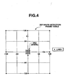
- the ROM of the control section 35 or the gain value storing section 38 stores white detection frame data 351, shown in FIG. 4, and EV (Exposure Value) determination data 352, shown in FIG. 5.
- the control section 35 starts a process in accordance with this flow chart on the basis of the above program.
- the control section 35 thus drives the CCD 25 by one frame (step S1).
- the control section 35 loads digital data for the driven frame (step 52).
- the control section 35 then loads a white detection value and an EV (Exposure Value) (step S3).
- the control section 35 determines whether or not the EV belongs to the data "dark" (step S4).
- step S4 is executed on the basis of the EV determination data, shown in FIG. 5, to determine whether or not the loaded EV belongs to the data "dark" of the EV determination data 352. If the loaded EV belongs to the data "dark" of the EV determination data 352 (step S4; YES), the loaded image data is estimated to have been photographed in the shade or using the sunlight, a fluorescent lamp, or a tungsten lamp as a light source.
- the No. determined under the condition 1 refers to the No. corresponding to the largest number of white portions (the number of pixels within a white frame 353 in the second gain value table 382) among the last 12 frames when the gain value Nos. 1 to 12 from the second gain . value table are sequentially set in the R amplifier 22a and B amplifier 22c of the second gain adjusting circuit 22 for each frame.
- the first gain adjusting circuit 21 is denoted as "#1" and the second gain adjusting circuit 22 is denoted as "#2"
- the gain value Nos. 1 to 12 are sequentially set in the R amplifier 22a and B amplifier 22c of the second gain adjusting circuit 22 (#2) for each frame.
- the data "dark” is denoted as "Dk”.
- the "number of white portions” is detected to determine the No. corresponding to the largest number of white portions among the last 12 frames.
- step S5 If the result of the determination in step S5 indicates that the gain value from the second gain value table 382 determined under the condition 1 is No. 1 or 2 (step S5; YES), then the No. 1 ⁇ for the shade is determined to be a gain candidate in the first gain value table 381 to be set in the R amplifier 21a and B amplifier 21c of the first gain adjusting circuit 21 (step S6).
- step S5 determines whether or not the gain value from the second gain value table 382 determined under the condition 1 is No. 3, 4, 5, 11, or 12 (step 57). If the result of the determination in step S7 is affirmative, the No. 2 ⁇ for the sunlight is determined to be a gain value candidate in the first gain value table 381 to be set in the R amplifier 21a and B amplifier 21c of the first gain adjusting circuit 21 (step S8).
- step 57 determines whether or not the gain value from the second gain value table 382 determined under the condition 1 is No. 6, 7, or 8 (step 39). If the result of the determination in step S9 is affirmative, the No. 3 ⁇ for a fluorescent lamp is determined to be a gain value candidate in the first gain value table 381 to be set in the R amplifier 21a and B amplifier 21c of the first gain adjusting circuit 21 (step S10).
- the No. 7 indicates the largest number of white portions, "100". Therefore, at the point in time of the frame 13 (point in time A), the result of the determination in step S9 is affirmative.
- the No. 3 ⁇ for a fluorescent lamp is determined to be a candidate in the first gain value table 381.
- step S9 determines whether the gain value from the second gain value table 382 determined under the condition 1 is not No. 6, 7, or 8 (step S9; NO). If the result of the determination in step S9 indicates that the gain value from the second gain value table 382 determined under the condition 1 is not No. 6, 7, or 8 (step S9; NO), then the No. 4 ⁇ for a fluorescent lamp is determined to be a gain value candidate in the first gain value table 381 to be set in the R amplifier 21a and B amplifier 21c of the first gain adjusting circuit 21 (step S11).
- step S4 determines whether or not this value belongs to the data "bright” (step S14). If the EV is determined to belong to the data "bright” (step S14; YES), the loaded image data is estimated to have been photographed using the sunlight as a light source.
- the No. 2 ⁇ for the sunlight is determined to be a gain value candidate in the first gain value table 381 to be set in the R amplifier 21a and B amplifier 21c of the first gain adjusting circuit 21 (step S15).
- step S14 determines whether or not the gain value from the second gain value table 382 determined under the condition 1 is No. 1 or 2 (step S16). Then, if the gain value from the second gain value table 382 determined under the condition 1 is No. 1 or 2 (step S16; YES), then the No. 1 ⁇ for the shade is determined to be a gain value candidate in the first gain value table 381 to be set in the R amplifier 21a and B amplifier 21c of the first gain adjusting circuit 21 (step S17).
- the gain value from the second gain value table 382 determined under the condition 1 is not No. 1 or 2 (step S16; NO)
- the No. 2 ⁇ for the sunlight is determined to be a gain value candidate in the first gain value table 381 to be set in the R amplifier 21a and B amplifier 21c of the first gain adjusting circuit 21 (step S18).
- step S12 it is determined whether or not the same No. has been determined to be a candidate 32 consecutive times in steps S6, S8, S10, S11, S15, S17, and S18 (step S12). If the same No. has not been determined to be a candidate 32 consecutive times (step S12; NO), the processing from step S1 is repeated. When the same No. has been determined to be a candidate 32 consecutive times (step S12; YES), the gain value corresponding to this No. is set in the R amplifier 21a and B amplifier 21c of the first gain adjusting circuit 21 for update (step S13).
- the number of times No. 3 ⁇ has been determined to be a candidate until then is 32. Accordingly, at the point in time B, the result of the determination in step S12 is affirmative, the initial value No. 2 ⁇ is changed to No. 3 ⁇ . Further, at a point in time C, the number of times No. 2 ⁇ has been determined to be a candidate until then since a point in time D, when the situation seems to have changed, is 32. Accordingly, also at the point in time C, the result of the determination in step S12 is affirmative, the value No. 3 ⁇ is changed-to No. 2 ⁇ .
- the R amplifier 21a and B amplifier 21c of the first gain adjusting circuit 21 use the gain value set in step S13, described previously, to amplify the R and B color components of the digital image data in the optical image transmitted by the unit circuit 28. Then, as described previously, the image signal amplified by the first gain adjusting circuit 21 is transmitted to the first color process circuit 23.
- the first color process circuit 23 executes a color process on the signal and writes the processed signal in the buffer of the DMA controller 29 as YUV data containing a digital luminous signal (Y signal) and color difference signals (Cb signal and Cr signal).
- the DMA controller 29 then transfers the YUV data written in the buffer to a designated area of the DRAM 30 for expansion.
- the video encoder 31 On the basis of the YUV data read from the buffer, the video encoder 31 generates a video signal and outputs it to the display device 32, composed of the LCD in the present embodiment.
- an image of a subject that maintains a favorable white balance is always displayed on the display device 32 as a through image without the need for a complicated operation of setting white balance in accordance with the light source.
- an image based on image data from the second gain adjusting circuit 22 for which the gain value Nos. 1 to 12 from the second gain value table 382 are sequentially set for each frame under the condition 1 an image based on image data from the second gain adjusting circuit 22 for which a gain value is updated and set is displayed on the display device 32 as a through image. This avoids a frequent variation in the white balance of the through image displayed on the display device 32.
- the recording control means of the control section 35 transmits one frame of YUV data written in the buffer to the compression/expansion section 33.
- the compression/expansion section 33 compresses the data and then records the compressed data in the flash memory 34.
- the image data on the subject image maintaining correct white balance can be recorded in the flush memory 34.
- the CCD 25 detects white portions in the entire image for one frame.
- the image P for one frame is divided into three parts, as shown in FIG. 8, including a central part Pc, an upper part Pu, and a lower part Pd, the subject is generally located in the central position Pc. Accordingly, white detection may be performed in a specified area of the image, e.g. in the upper part Pu or lower part Pd but not in the central part Pc.
- the EV value itself is used for the EV determination.
- an average value of the several EV values may be used for the EV determination. Then, the determination can be accomplished stably without being affected by a change in EV during a short time.
- the electronic still camera has been mainly described, which records, when the shutter key is depressed with a through image displayed, an image picked up at that time.
- the present invention is not limited to such an electronic still camera.
- the present invention is applicable to other apparatuses as long as they can execute auto white balance control on picked-up images.
Landscapes
- Engineering & Computer Science (AREA)
- Multimedia (AREA)
- Signal Processing (AREA)
- Color Television Image Signal Generators (AREA)
- Processing Of Color Television Signals (AREA)
Abstract
Description
- The present invention relates to an image pickup apparatus, a white balance control method, and a white balance control program.
- Electronic still cameras, which belong to image pickup apparatuses, are, in some cases, provided with an auto white balance function of automatically setting the white balance of an image to be picked up.
- For auto white balance, it is necessary to determine which part of an image to be picked up is white. However, if a subject contains a color similar to white such as a light blue or a flesh color, then at the white determining stage, there is a possibility that such a color similar to white may be determined as real white. Accordingly, in such a situation, what is called a "drawing effect" may occur in which a white subject appears bluish, while a red subject appears light red. Consequently, a liquid crystal monitor may display through images with the drawing effects. Of course, if a shutter of the electronic camera is depressed in such a situation, a recorded image has an inappropriate white balance.
- The term "through images" as used herein means images sequentially picked up by image pickup means and displayed on the monitor to allow a user to check the subject while the image pickup device is in an image pickup standby state.
- According to an aspect of the present invention, there is provided an image pickup apparatus comprising:
- an image pickup device which picks up an image of a subject to output an image pickup signal;
- first and second amplifying units configured to individually amplify color components of the image pickup signal outputted by the image pickups device;
- a first storage unit configured to store plural types of gain values for the respective color components which are used to maintain a white balance of the subject;
- a varying unit configured to sequentially vary the gain values for the respective color components from the second amplifying unit;
- gain value detecting unit configured to detect a gain value having color information contained in a predetermined white detection range on the basis of image information generated using the image pickup signal amplified by the second amplifying unit using the gain values for the respective color components sequentially varied by the varying unit;
- gain value selecting unit configured to select a gain value to be set in the first amplifying unit, from the first storage unit on the basis of the gain value detected by the detecting unit;
- gain value setting unit configured to set the gain value selected by the selecting unit, in the first amplifying unit; and
- recording control unit configured to use the gain value set by the setting unit to cause the image information generated using the image pickup signal amplified by the first amplifying unit to be recorded in an image recording section.
-
- According to another aspect of the present invention, there is provided a white balance control method in an image pickup apparatus comprising image pickup unit configured to pick up an image of a subject to output an image pickup signal, first and second amplifying unit configured to individually amplify color components of the image pickup signal outputted by the image pickup unit, and gain value storage unit configured to store plural types of gain values for the respective color components which are used to maintain a white balance of the subject, the method comprising:
- sequentially varying the gain values for the respective color components from the second amplifying unit;
- detecting a gain value having color information contained in a predetermined white detection range on the basis of image information generated using the image pickup signal amplified by the second amplifying unit using the gain values for the respective color components sequentially varied;
- selecting a gain value to be set in the first amplifying unit, from the first storage unit on the basis of the gain value detected;
- setting the gain value selected, in the first amplifying unit; and
- controlling the recording of the image information using the set gain value to cause the image information generated using the image pickup signal amplified by the first amplifying unit to be recorded in an image recording section.
-
- According to further aspect of the present invention, there is provided an image pickup apparatus comprising:
- an image pickup device which picks up an image of a subject to output an image pickup signal;
- first and second amplifying units configured to individually amplify color components of the image pickup signal outputted by the image pickup device;
- first storage unit configured to store plural types of gain values for the respective color components which are used to maintain a white balance of the subject;
- varying unit configured to sequentially vary the gain values for the respective color components from the second amplifying unit;
- gain value detecting unit configured to detect a gain value having color information contained in a predetermined white detection range on the basis of image information generated using the image pickup signal amplified by the second amplifying unit using the gain values for the respective color components sequentially varied by the varying unit;
- gain value selecting unit configured to select a gain value to be set in the first amplifying unit, from the first storage unit on the basis of the gain value detected by the detecting unit;
- gain value setting unit configured to set the gain value selected by the selecting unit, in the first amplifying unit; and
- display control unit configured to use the gain value set by the setting unit to cause an image display section to display the image information generated using the image pickup signal amplified by the first amplifying unit.
-
- This summary of the invention does not necessarily describe all necessary features so that the invention may also be a sub-combination of these described features.
- The invention can be more fully understood from the following detailed description when taken in conjunction with the accompanying drawings, in which:
- FIG. 1 is a block diagram showing a structure of an electronic still camera according to a first embodiment of the present invention;
- FIGS. 2A and 2B are, inclusively, tables showing gain values stored in a first gain value table together with an explanation thereof;
- FIGS. 3A and 3B are, inclusively, tables showing gain values stored in the first gain value table together with an explanation thereof;
- FIG. 4 is a table showing white detection frame data;
- FIG. 5 is a table showing EV value determination data;
- FIG. 6 is a flow chart showing operations in an REC through mode according to the present embodiment;
- FIG. 7 is a table showing a specific example of operations in the REC through mode according to the present embodiment; and
- FIG. 8 is a diagram illustrating a white detecting method according to another embodiment of the present invention.
-
- A first embodiment of the present invention will be described below with reference to the drawings. FIG. 1 is a block diagram of an electronic still camera according to a first embodiment of the present invention.
- A
CCD 25 arranged behind anobjective lens 20 is driven by a timing generator (TG) 26 through avertical driver 27. TheCCD 25 is provided with an array of color filters for primary colors R, G, and B. An optical image formed on a light receiving surface of theCCD 25 by thelens 20 is stored in light receiving sections R (Red), G (Green), and B (Blue) as charges and converted into R, G, and B signal charges the amounts of which are based on the intensity of the respective color light components. Then, the resulting analog image signal is outputted to aunit circuit 28. Theunit circuit 28 is composed of a correlated double sampler (CDS) that removes noise included in the input image pickup signal and an A/D converter that converts the image pickup signal free from the noise into digital image data. The image data outputted by theunit circuit 28 is transmitted to a first gain adjusting circuit 21 (first amplifying unit) and a second gain adjusting circuit 22 (second amplifying unit). - The first and second
gain adjusting circuits R amplifiers G amplifiers B amplifiers control section 35 transmits control signals to control the gains of theamplifiers gain adjusting circuit 21 is transmitted to a firstcolor process circuit 23. The firstcolor process circuit 23 executes color processing on the signal and then writes the processed signal in a buffer of a DMA (Direct Memory Access)controller 29 as YUV data containing a digital luminous signal (Y signal) and color difference signals (Cb signal and Cr signal). At the same time, the R, G, and B image data that has not undergone the color process is also written in the buffer. TheDMA controller 29 transfers the YUV data written in the buffer to a designated area in aDRAM 30 for expansion. - A
video encoder 31 generates a video signal on the basis of the YUV data read from the buffer and then outputs it to adisplay device 32 composed of an LCD (Liquid Crystal Display). Thus, when an REC through mode in an image pickup standby status is set, the picked up image of the subject is displayed on thedisplay device 32 as a through image. Further, in this situation, when a shutter key is depressed to give an instruction on photographing, one frame of YUV data written in the buffer is transmitted to a compression/expansion section 33. The compression/expansion section 33 compresses the data and then records the compressed data in aflash memory 34. When a PLAY mode is set for image reproduction or the like, the image data recorded in theflash memory 34 is transmitted to the compression/expansion section 33 via theDMA controller 29. The compression/expansion section 33 performs the data expansion operation to reproduce YUV data. Thus, the recorded image is displayed on thedisplay device 32. - On the other hand, an image signal amplified by the second
gain adjusting circuit 22 is transmitted to a secondcolor process circuit 24. The secondcolor process circuit 24 executes a color process on the image signal and then transmits the processed signal to acontrol section 35 as YUV data containing a digital luminous signal (Y signal) and color difference signals (Cb signal and Cr signal). - The
control section 35 has a central processing unit (CPU), a ROM in which programs and data are stored, and a work RAM. Thecontrol section 35 controls operations of the previously described sections in accordance with predetermined programs. It also responds to status signals transmitted by anoperation section 36 to carry out the functions of the electronic still camera, i.e. auto exposure (AE) control and auto white balance (AWB). - The
operation section 36 is provided with keys such as the shutter key and a key for switching between the REC through mode and the PLAY mode. Theoperation section 36 thus transmits the status signal to thecontrol section 35 in accordance with a key operation. Astroboscope 37 is driven as required when the shutter key is operated (when an image is photographed) to emit auxiliary light. Thecontrol section 35 also operates as gain value varying means, gain value detecting means, gain value selecting means, gain value setting means, and recording control means, using a CPU provided therein. - A gain
value storing section 38 stores gain values set in theR amplifiers 21a andB amplifiers 21c of the firstgain adjusting circuit 21 when thecontrol section 35 carries out auto white balance control. The gainvalue storing section 38 also stores gain values set in theR amplifiers 22a andB amplifiers 22c of the secondgain adjusting circuit 22 when thecontrol section 35 carries out auto white balance control. Specifically, the gainvalue storing section 38 stores a first gain value table 381 as first gain value storing means, shown in FIG. 2A, and a second gain value table 382 as second gain value storing means, shown in FIG. 3A. - The first gain value table 381 is used when the
control section 35 carries out auto white balance control to cause theR amplifiers 21a andB amplifiers 21c of the firstgain adjusting circuit 21 to execute amplification. The first gain value table 381 stores R gain values corresponding to gain value Nos. 1 ○ to 4 ○ and B gain values corresponding to gain value Nos. 1 ○ to 4 ○. Here, the gain value No. 1 ○ denotes photographing in the shade, the gain value No. 2 ○ denotes sunlight, the gain value No. 3 ○ denotes a fluorescent lamp, and the gain value No. 4 ○ denotes a tungsten lamp. That is, when any of these light sources is used for photographing, the corresponding R and B gain values can be used to set the appropriate white balance. Further, these R and B gain values have been defined experimentally or empirically. - The second gain value table 382 is used when the
control section 35 carries out auto white balance control to cause theR amplifiers 22a andB amplifiers 22c of the secondgain adjusting circuit 22 to execute amplification. The second gain value table 382 stores R gain values corresponding to gainnumbers 1 to 12 and B gain values corresponding to gainnumbers 1 to 12. Here, the gain value Nos. 1 and 2 denote photographing in the shade, the gain value Nos. 3, 4, and 5 denote sunlight, the gain value Nos. 6, 7, and 8 denote a fluorescent lamp, thegain value 9 denotes a tungsten lamp, and thegain value 10 denotes an incandescent lamp. That is, when any of these light sources is used for photographing, the corresponding R and B gain values can be used to set the appropriate white balance. Further, thegain value 11 indicates that the subject is green, and thegain value 12 indicates that the subject is beige. That is, in either of these situations, the corresponding R and B gain values can be used to set the appropriate white balance. These R and B gain values have also been defined experimentally or empirically. - In the first gain value table 381 and the second gain value table 382, the pair of the gain value Nos. 1 ○ and 1, the pair of the gain value Nos. 2 ○ and 4, the pair of the gain value Nos. 3 ○ and 6, and the pair of the gain value Nos. 4 ○ and 9 each correspond to the same R and B gain values.
- Further, the ROM of the
control section 35 or the gainvalue storing section 38 stores whitedetection frame data 351, shown in FIG. 4, and EV (Exposure Value)determination data 352, shown in FIG. 5. - Now, with reference to the flow chart shown in FIG. 6, description will be given of operations in the REC through mode with an AWB mode set according to the present embodiment configured as described above. The operations in the flow chart shown in FIG. 6 are performed by using the CPU of the
control section 35 as gain value varying means, gain value detecting means, gain value selecting means, or gain value setting means in accordance with a predetermined program stored in the ROM. - Specifically, in the electronic still camera, when the REC through mode is set, the
control section 35 starts a process in accordance with this flow chart on the basis of the above program. Thecontrol section 35 thus drives theCCD 25 by one frame (step S1). Then, thecontrol section 35 loads digital data for the driven frame (step 52). Thecontrol section 35 then loads a white detection value and an EV (Exposure Value) (step S3). Then, thecontrol section 35 determines whether or not the EV belongs to the data "dark" (step S4). - The processing in step S4 is executed on the basis of the EV determination data, shown in FIG. 5, to determine whether or not the loaded EV belongs to the data "dark" of the
EV determination data 352. If the loaded EV belongs to the data "dark" of the EV determination data 352 (step S4; YES), the loaded image data is estimated to have been photographed in the shade or using the sunlight, a fluorescent lamp, or a tungsten lamp as a light source. - In this case, it is determined whether or not the gain value No. determined under a
condition 1 is No. 1 or 2 of the gain value Nos. 1 to 12 from the second gain value table 382 (step S5). Here, the No. determined under thecondition 1 refers to the No. corresponding to the largest number of white portions (the number of pixels within awhite frame 353 in the second gain value table 382) among the last 12 frames when the gain value Nos. 1 to 12 from the second gain . value table are sequentially set in theR amplifier 22a andB amplifier 22c of the secondgain adjusting circuit 22 for each frame. - That is, as shown in the specific example in FIG. 7 (in FIG. 7, the first
gain adjusting circuit 21 is denoted as "#1" and the secondgain adjusting circuit 22 is denoted as "#2"), when the EV is determined to belong to the data "dark", the gain value Nos. 1 to 12 are sequentially set in theR amplifier 22a andB amplifier 22c of the second gain adjusting circuit 22 (#2) for each frame. In FIG. 7, the data "dark" is denoted as "Dk". Thus, the "number of white portions" is detected to determine the No. corresponding to the largest number of white portions among the last 12 frames. - If the result of the determination in step S5 indicates that the gain value from the second gain value table 382 determined under the
condition 1 is No. 1 or 2 (step S5; YES), then the No. 1 ○ for the shade is determined to be a gain candidate in the first gain value table 381 to be set in theR amplifier 21a andB amplifier 21c of the first gain adjusting circuit 21 (step S6). - On the other hand, if the result of the determination in step S5 indicates that the gain value from the second gain value table 382 determined under the
condition 1 is not No. 1 or 2 (step 35; NO), then it is determined whether or not the gain value from the second gain value table 382 determined under thecondition 1 is No. 3, 4, 5, 11, or 12 (step 57). If the result of the determination in step S7 is affirmative, the No. 2 ○ for the sunlight is determined to be a gain value candidate in the first gain value table 381 to be set in theR amplifier 21a andB amplifier 21c of the first gain adjusting circuit 21 (step S8). - Further, if the result of the determination in
step 57 indicates that the gain value from the second gain value table 382 determined under thecondition 1 is not No. 3, 4, 5, 11, or 12 (step 57; NO), then it is determined whether or not the gain value from the second gain value table 382 determined under thecondition 1 is No. 6, 7, or 8 (step 39). If the result of the determination in step S9 is affirmative, the No. 3 ○ for a fluorescent lamp is determined to be a gain value candidate in the first gain value table 381 to be set in theR amplifier 21a andB amplifier 21c of the first gain adjusting circuit 21 (step S10). - That is, in the specific example shown in FIG. 1, of the gain value Nos. 1, 2, 3, ..., 12 set for
frames - Further, if the result of the determination in step S9 indicates that the gain value from the second gain value table 382 determined under the
condition 1 is not No. 6, 7, or 8 (step S9; NO), then the No. 4 ○ for a fluorescent lamp is determined to be a gain value candidate in the first gain value table 381 to be set in theR amplifier 21a andB amplifier 21c of the first gain adjusting circuit 21 (step S11). - On the other hand, if the result of the determination in step S4 indicates that the loaded EV does not belong to the data "dark" of the EV determination data 352 (step S4; NO), it is determined whether or not this value belongs to the data "bright" (step S14). If the EV is determined to belong to the data "bright" (step S14; YES), the loaded image data is estimated to have been photographed using the sunlight as a light source. Thus, in this case, as with step S8, described previously, the No. 2 ○ for the sunlight is determined to be a gain value candidate in the first gain value table 381 to be set in the
R amplifier 21a andB amplifier 21c of the first gain adjusting circuit 21 (step S15). - However, if the result of the determination in step S14 indicates that the loaded EV does not belong to the data "bright" of the EV determination data 352 (step S14; NO), then as with step S5, described previously, it is determined whether or not the gain value from the second gain value table 382 determined under the
condition 1 is No. 1 or 2 (step S16). Then, if the gain value from the second gain value table 382 determined under thecondition 1 is No. 1 or 2 (step S16; YES), then the No. 1 ○ for the shade is determined to be a gain value candidate in the first gain value table 381 to be set in theR amplifier 21a andB amplifier 21c of the first gain adjusting circuit 21 (step S17). However, if the gain value from the second gain value table 382 determined under thecondition 1 is not No. 1 or 2 (step S16; NO), then the No. 2 ○ for the sunlight is determined to be a gain value candidate in the first gain value table 381 to be set in theR amplifier 21a andB amplifier 21c of the first gain adjusting circuit 21 (step S18). - Then, it is determined whether or not the same No. has been determined to be a
candidate 32 consecutive times in steps S6, S8, S10, S11, S15, S17, and S18 (step S12). If the same No. has not been determined to be acandidate 32 consecutive times (step S12; NO), the processing from step S1 is repeated. When the same No. has been determined to be acandidate 32 consecutive times (step S12; YES), the gain value corresponding to this No. is set in theR amplifier 21a andB amplifier 21c of the firstgain adjusting circuit 21 for update (step S13). - That is, in the specific example shown in FIG. 7, at a point in time B, the number of times No. 3 ○ has been determined to be a candidate until then is 32. Accordingly, at the point in time B, the result of the determination in step S12 is affirmative, the initial value No. 2 ○ is changed to No. 3 ○. Further, at a point in time C, the number of times No. 2 ○ has been determined to be a candidate until then since a point in time D, when the situation seems to have changed, is 32. Accordingly, also at the point in time C, the result of the determination in step S12 is affirmative, the value No. 3 ○ is changed-to No. 2 ○.
- Therefore, the
R amplifier 21a andB amplifier 21c of the firstgain adjusting circuit 21 use the gain value set in step S13, described previously, to amplify the R and B color components of the digital image data in the optical image transmitted by theunit circuit 28. Then, as described previously, the image signal amplified by the firstgain adjusting circuit 21 is transmitted to the firstcolor process circuit 23. The firstcolor process circuit 23 executes a color process on the signal and writes the processed signal in the buffer of theDMA controller 29 as YUV data containing a digital luminous signal (Y signal) and color difference signals (Cb signal and Cr signal). TheDMA controller 29 then transfers the YUV data written in the buffer to a designated area of theDRAM 30 for expansion. On the basis of the YUV data read from the buffer, thevideo encoder 31 generates a video signal and outputs it to thedisplay device 32, composed of the LCD in the present embodiment. - Thus, when the REC through mode in the image pickup standby status is set, an image of a subject that maintains a favorable white balance is always displayed on the
display device 32 as a through image without the need for a complicated operation of setting white balance in accordance with the light source. Further, instead of an image based on image data from the secondgain adjusting circuit 22 for which the gain value Nos. 1 to 12 from the second gain value table 382 are sequentially set for each frame under thecondition 1, an image based on image data from the secondgain adjusting circuit 22 for which a gain value is updated and set is displayed on thedisplay device 32 as a through image. This avoids a frequent variation in the white balance of the through image displayed on thedisplay device 32. - When the shutter key is depressed to give an instruction on photographing, the recording control means of the
control section 35 transmits one frame of YUV data written in the buffer to the compression/expansion section 33. The compression/expansion section 33 compresses the data and then records the compressed data in theflash memory 34. Thus, the image data on the subject image maintaining correct white balance can be recorded in theflush memory 34. - In the present embodiment, the
CCD 25 detects white portions in the entire image for one frame. However, if the image P for one frame is divided into three parts, as shown in FIG. 8, including a central part Pc, an upper part Pu, and a lower part Pd, the subject is generally located in the central position Pc. Accordingly, white detection may be performed in a specified area of the image, e.g. in the upper part Pu or lower part Pd but not in the central part Pc. - Further, in the present embodiment, the EV value itself is used for the EV determination. However, an average value of the several EV values may be used for the EV determination. Then, the determination can be accomplished stably without being affected by a change in EV during a short time.
- Furthermore, in the present embodiment, the electronic still camera has been mainly described, which records, when the shutter key is depressed with a through image displayed, an image picked up at that time. However, the present invention is not limited to such an electronic still camera. The present invention is applicable to other apparatuses as long as they can execute auto white balance control on picked-up images.
Claims (10)
- An image pickup apparatus characterized by comprising:an image pickup means (25) for picking up an image of a subject to output an image pickup signal;first and second amplifying means (21, 22) for individually amplifying color components of the image pickup signal outputted by the image pickup means;first storage means (38) for storing plural types of gains for the respective color components which are used to maintain a white balance of the subject;varying means (35) for sequentially varying the gains for the respective color components from the second amplifying means;detecting means (35) for detecting a gain having color information contained in a predetermined white detection range on the basis of image information generated using the image pickup signal amplified by the second amplifying means using the gains for the respective color components sequentially varied by the varying means;selecting means (35) for selecting a gain to be set in the first amplifying means, from the first storage means on the basis of the gain detected by the detecting means;setting means (35) for setting the gain selected by the selecting means, in the first amplifying means; andcontrol means (35) to allow the image information generated using the image pickup signal amplified by the first amplifying means to be used for display or recorded according to the gain set by the setting means.
- An image pickup apparatus according to claim 1, characterized by further comprising: second storage means (382) for storing plural types of gains for the respective color components to be set in the second amplifying means (22), and
wherein the varying means (35) sequentially varies the gains for the respective color components by sequentially setting the plural types of gains stored in the second storage means (382), in the second amplifying means (22). - An image pickup apparatus according to claim 2, characterized in that the second storage means (382) stores more types of gains than the first storage means (381).
- An image pickup apparatus according to claim 1 or claim 2, characterized in that the selecting means (35) selects one of the gains stored in the first storage means (381),'as a candidate, on the basis of the gain detected by the detecting means (35), and if this gain has been selected as a candidate
a predetermined consecutive number of times, the selecting means (35) finally selects the gain selected as a candidate, as a gain to be set in the first amplifying means (21). - An image pickup apparatus according to one of claims 1 to 4, characterized in that the plural types of gains stored in the first storage means (381) are gains for the respective color components with which the white balance of the subject is maintained in the shade and under sunlight, a fluorescent lamp, and a tungsten lamp, respectively.
- An image pickup apparatus according to claim 5, characterized by further comprising exposure determining means (35, 38) for determining exposure when the image pickup means (25) picks up an image of the subject, and
wherein the selecting means (35) selects the gain to be set in the first amplifying means (21), from the first storage means (381), on the basis of the exposure determined by the exposure determining means (35, 38) and the gain detected by the detecting means (35). - An image pickup apparatus according to claim 1, characterized by further comprising display means (32) for displaying an image on the basis of image information supplied by the control means (35).
- The image pickup apparatus according to. claim 1 or claim 7, characterized by further comprising recording means (34) for recording image information supplied by the control means (35), in response to a photographing operation.
- A white balance control method in an image pickup apparatus comprising image pickup means (25) for picking up an image of a subject to output an image pickup signal, first and second amplifying means (21, 22) for individually amplifying color components of the image pickup signal outputted by the image pickup means (25), and storage means (38) for storing plural types of gains for the respective color components which are used to maintain a whitebalance of the subject, the method characterized by comprising:a varying step of sequentially varying the gains for the respective color components from the second amplifying means (382);a detecting step of detecting a gain having color information contained in a predetermined white detection range on the basis of image information generated using the image pickup signal amplified by the second amplifying means (22) using the gains for the respective color components sequentially varied by the varying step;a selecting step of selecting a gain to be set in the first amplifying means (21), from the storage means (38) on the basis of the gain detected by the detecting step;a setting step of setting the gain selected by the selecting step, in the first amplifying means (21); anda control step of using the gain set by the setting step to allow the image information generated using the image pickup signal amplified by the first amplifying means (21) to be used for display or recorded.
- A white balance control program used in a computer having an image pickup apparatus comprising an image pickup means (25) for picking up an image of a subject to output an image pickup signal, first and second amplifying means (21, 22) for individually amplifying color components of the image pickup signal outputted by the image pickup means (25), and storage means (38) for storing plural types of gains for the respective color components which are used to maintain a white balance of the subject, the program allowing the computer to function as:varying means (35) for sequentially varying the gains for the respective color components from the second amplifying means (22);detecting means (35) for detecting a gain having color information contained in a predetermined white detection range on the basis of image information generated using the image pickup signal amplified by the second amplifying means (22) using the gains for the respective color components sequentially varied by the varying means (35);selecting means (35) for selecting a gain to be set in the first amplifying means (21), from the storage means (38) on the basis of the gain detected by the detecting means (35);setting means (35) for setting the gain selected by the selecting means (35), in the first amplifying means (22); andcontrol means (35) for using the gain value set by the setting means (35) to allow the image information generated using the image pickup signal amplified by the first amplifying means (21) to be used for display or recorded.
Applications Claiming Priority (2)
| Application Number | Priority Date | Filing Date | Title |
|---|---|---|---|
| JP2002173873A JP3630149B2 (en) | 2002-06-14 | 2002-06-14 | Imaging apparatus, white balance control method, and white balance control program |
| JP2002173873 | 2002-06-14 |
Publications (2)
| Publication Number | Publication Date |
|---|---|
| EP1372344A1 true EP1372344A1 (en) | 2003-12-17 |
| EP1372344B1 EP1372344B1 (en) | 2004-12-22 |
Family
ID=29561808
Family Applications (1)
| Application Number | Title | Priority Date | Filing Date |
|---|---|---|---|
| EP03013570A Expired - Lifetime EP1372344B1 (en) | 2002-06-14 | 2003-06-13 | Image pickup apparatus, white balance control method and white balance control program |
Country Status (7)
| Country | Link |
|---|---|
| US (1) | US7436439B2 (en) |
| EP (1) | EP1372344B1 (en) |
| JP (1) | JP3630149B2 (en) |
| KR (1) | KR100518735B1 (en) |
| CN (1) | CN1230008C (en) |
| DE (1) | DE60300231T2 (en) |
| TW (1) | TWI223566B (en) |
Families Citing this family (11)
| Publication number | Priority date | Publication date | Assignee | Title |
|---|---|---|---|---|
| US7224383B2 (en) | 2003-01-09 | 2007-05-29 | Hewlett-Packard Development Company, L.P. | Manipulating digital images based on a user profile |
| US7456869B2 (en) * | 2003-05-27 | 2008-11-25 | Olympus Corporation | Imaging device and imaging device adjusting method |
| JP4305327B2 (en) * | 2003-08-26 | 2009-07-29 | カシオ計算機株式会社 | Imaging apparatus, white balance control method, and white balance control program |
| JP4504031B2 (en) * | 2004-01-22 | 2010-07-14 | オリンパス株式会社 | Camera system |
| JP4033140B2 (en) | 2004-02-10 | 2008-01-16 | カシオ計算機株式会社 | Imaging apparatus, white balance control method, and white balance control program |
| JP4433937B2 (en) * | 2004-08-24 | 2010-03-17 | ソニー株式会社 | IMAGING DEVICE, IMAGING METHOD, IMAGING PROGRAM, RECORDING DEVICE, RECORDING METHOD, AND RECORDING PROGRAM |
| CN100428783C (en) * | 2005-06-01 | 2008-10-22 | 索尼株式会社 | Image processing device, liquid crystal display device and color correction method |
| CN100571407C (en) * | 2005-12-14 | 2009-12-16 | 联阳半导体股份有限公司 | White balance control method |
| JP4914651B2 (en) * | 2006-06-12 | 2012-04-11 | オリンパスイメージング株式会社 | Electronic imaging apparatus and electronic imaging method |
| US7864467B2 (en) * | 2008-02-06 | 2011-01-04 | International Business Machines Corporation | Gain control for data-dependent detection in magnetic storage read channels |
| US9247223B2 (en) | 2013-01-25 | 2016-01-26 | Blackberry Limited | Reduce operating environment effect using multiple cameras |
Citations (2)
| Publication number | Priority date | Publication date | Assignee | Title |
|---|---|---|---|---|
| US4679066A (en) * | 1982-06-09 | 1987-07-07 | Canon Kabushiki Kaisha | Color image pickup device |
| EP1045594A2 (en) * | 1999-03-25 | 2000-10-18 | Texas Instruments Incorporated | Programmable real-time image processing |
Family Cites Families (22)
| Publication number | Priority date | Publication date | Assignee | Title |
|---|---|---|---|---|
| JPS58215884A (en) * | 1982-06-10 | 1983-12-15 | Sony Corp | Electronic camera |
| US4899212A (en) * | 1987-08-28 | 1990-02-06 | Fuji Photo Film Co., Ltd. | White balance adjusting device for a camera |
| US5617139A (en) * | 1987-09-10 | 1997-04-01 | Canon Kabushiki Kaisha | Image pickup apparatus |
| US5223921A (en) * | 1990-04-27 | 1993-06-29 | Sanyo Electric Co., Ltd. | White balance adjusting apparatus for automatically adjusting white balance on the basis of a color information signal obtained from an image-sensing device |
| JPH0470179A (en) | 1990-07-10 | 1992-03-05 | Matsushita Electric Ind Co Ltd | Electronic still camera device |
| JPH07245764A (en) | 1994-03-04 | 1995-09-19 | Fuji Photo Film Co Ltd | Automatic white balance device |
| JP3535678B2 (en) | 1996-11-18 | 2004-06-07 | コニカミノルタホールディングス株式会社 | White balance adjustment device for still video cameras |
| JPH10243414A (en) | 1997-02-28 | 1998-09-11 | Hewlett Packard Co <Hp> | Color balance adjustment method, program memory and digital camera |
| JPH1141619A (en) * | 1997-07-24 | 1999-02-12 | Sony Corp | Color signal processing circuit, processing method thereof, and camera using the same |
| JP3631022B2 (en) | 1997-12-25 | 2005-03-23 | キヤノン株式会社 | Imaging apparatus and signal processing apparatus |
| JP4212134B2 (en) * | 1997-12-25 | 2009-01-21 | 三洋電機株式会社 | Image signal processing device |
| JP4532613B2 (en) * | 1998-11-25 | 2010-08-25 | キヤノン株式会社 | Imaging method and apparatus, and storage medium |
| JP4327928B2 (en) * | 1999-02-26 | 2009-09-09 | メディア・テック・ユーエスエイ・インコーポレーテッド | Electronic camera device |
| JP3896438B2 (en) | 1999-04-12 | 2007-03-22 | 富士フイルム株式会社 | Digital camera and auto white balance control method |
| JP4081581B2 (en) | 1999-04-26 | 2008-04-30 | 富士フイルム株式会社 | Auto white balance control method |
| JP4284754B2 (en) * | 1999-05-31 | 2009-06-24 | ソニー株式会社 | Color imaging apparatus and control method thereof |
| JP3925065B2 (en) | 2000-04-13 | 2007-06-06 | カシオ計算機株式会社 | Electronic camera and auto white balance control method |
| JP4004220B2 (en) | 2000-10-05 | 2007-11-07 | 株式会社リコー | WHITE BALANCE ADJUSTMENT DEVICE, WHITE BALANCE ADJUSTMENT METHOD, AND COMPUTER READABLE RECORDING MEDIUM CONTAINING PROGRAM FOR EXECUTING THE METHOD IN COMPUTER |
| JP4826028B2 (en) * | 2001-05-24 | 2011-11-30 | 株式会社ニコン | Electronic camera |
| US7184080B2 (en) * | 2001-06-25 | 2007-02-27 | Texas Instruments Incorporated | Automatic white balancing via illuminant scoring |
| JP4439767B2 (en) | 2001-08-09 | 2010-03-24 | キヤノン株式会社 | Imaging apparatus, white balance adjustment method, and operation processing program thereof |
| JP4305327B2 (en) * | 2003-08-26 | 2009-07-29 | カシオ計算機株式会社 | Imaging apparatus, white balance control method, and white balance control program |
-
2002
- 2002-06-14 JP JP2002173873A patent/JP3630149B2/en not_active Expired - Fee Related
-
2003
- 2003-06-13 TW TW092116092A patent/TWI223566B/en not_active IP Right Cessation
- 2003-06-13 CN CNB031407862A patent/CN1230008C/en not_active Expired - Fee Related
- 2003-06-13 US US10/461,772 patent/US7436439B2/en active Active
- 2003-06-13 DE DE60300231T patent/DE60300231T2/en not_active Expired - Lifetime
- 2003-06-13 EP EP03013570A patent/EP1372344B1/en not_active Expired - Lifetime
- 2003-06-13 KR KR10-2003-0038119A patent/KR100518735B1/en not_active Expired - Fee Related
Patent Citations (2)
| Publication number | Priority date | Publication date | Assignee | Title |
|---|---|---|---|---|
| US4679066A (en) * | 1982-06-09 | 1987-07-07 | Canon Kabushiki Kaisha | Color image pickup device |
| EP1045594A2 (en) * | 1999-03-25 | 2000-10-18 | Texas Instruments Incorporated | Programmable real-time image processing |
Also Published As
| Publication number | Publication date |
|---|---|
| CN1230008C (en) | 2005-11-30 |
| KR100518735B1 (en) | 2005-10-06 |
| US7436439B2 (en) | 2008-10-14 |
| DE60300231T2 (en) | 2005-06-02 |
| DE60300231D1 (en) | 2005-01-27 |
| JP3630149B2 (en) | 2005-03-16 |
| EP1372344B1 (en) | 2004-12-22 |
| TW200401570A (en) | 2004-01-16 |
| KR20030096069A (en) | 2003-12-24 |
| CN1469636A (en) | 2004-01-21 |
| TWI223566B (en) | 2004-11-01 |
| JP2004023343A (en) | 2004-01-22 |
| US20030231248A1 (en) | 2003-12-18 |
Similar Documents
| Publication | Publication Date | Title |
|---|---|---|
| KR100816943B1 (en) | Image pickup apparatus and white balance control method | |
| JP5007523B2 (en) | Imaging apparatus and program thereof | |
| US7683966B2 (en) | Digital camera having an electronic flash device using LED as a flash light source | |
| US20010004268A1 (en) | Digital camera | |
| KR100689307B1 (en) | Imager and Auto White Balance Control Method | |
| JPH08340542A (en) | Electronic still camera | |
| US7436439B2 (en) | Image pickup apparatus, gain control method, and gain control program, which sequentially set gain values in a gain adjusting circuit to select a gain value to be set in another gain adjusting circuit to maintain white balance | |
| JP4774915B2 (en) | Imaging apparatus, gradation correction method, and program | |
| JP4530742B2 (en) | Monitor control device | |
| JP2003324755A (en) | Image processing apparatus and method, recording medium, and program | |
| JP3845771B2 (en) | Imaging apparatus, white balance control method, and white balance control program | |
| HK1095237B (en) | Image pickup apparatus and white balance control method | |
| US20050259178A1 (en) | Image taking apparatus | |
| JPH11168747A (en) | Imaging device | |
| JP2008022474A (en) | Imaging apparatus and imaging processing method | |
| JPH11341313A (en) | Digital camera and its control method |
Legal Events
| Date | Code | Title | Description |
|---|---|---|---|
| PUAI | Public reference made under article 153(3) epc to a published international application that has entered the european phase |
Free format text: ORIGINAL CODE: 0009012 |
|
| 17P | Request for examination filed |
Effective date: 20030613 |
|
| AK | Designated contracting states |
Kind code of ref document: A1 Designated state(s): AT BE BG CH CY CZ DE DK EE ES FI FR GB GR HU IE IT LI LU MC NL PT RO SE SI SK TR |
|
| AX | Request for extension of the european patent |
Extension state: AL LT LV MK |
|
| GRAP | Despatch of communication of intention to grant a patent |
Free format text: ORIGINAL CODE: EPIDOSNIGR1 |
|
| AKX | Designation fees paid |
Designated state(s): DE FR GB IT |
|
| GRAS | Grant fee paid |
Free format text: ORIGINAL CODE: EPIDOSNIGR3 |
|
| GRAA | (expected) grant |
Free format text: ORIGINAL CODE: 0009210 |
|
| AK | Designated contracting states |
Kind code of ref document: B1 Designated state(s): DE FR GB IT |
|
| REG | Reference to a national code |
Ref country code: GB Ref legal event code: FG4D |
|
| REG | Reference to a national code |
Ref country code: IE Ref legal event code: FG4D |
|
| REF | Corresponds to: |
Ref document number: 60300231 Country of ref document: DE Date of ref document: 20050127 Kind code of ref document: P |
|
| PLBE | No opposition filed within time limit |
Free format text: ORIGINAL CODE: 0009261 |
|
| STAA | Information on the status of an ep patent application or granted ep patent |
Free format text: STATUS: NO OPPOSITION FILED WITHIN TIME LIMIT |
|
| ET | Fr: translation filed | ||
| 26N | No opposition filed |
Effective date: 20050923 |
|
| REG | Reference to a national code |
Ref country code: FR Ref legal event code: PLFP Year of fee payment: 14 |
|
| REG | Reference to a national code |
Ref country code: FR Ref legal event code: PLFP Year of fee payment: 15 |
|
| PGFP | Annual fee paid to national office [announced via postgrant information from national office to epo] |
Ref country code: FR Payment date: 20170511 Year of fee payment: 15 Ref country code: GB Payment date: 20170607 Year of fee payment: 15 Ref country code: DE Payment date: 20170606 Year of fee payment: 15 |
|
| PGFP | Annual fee paid to national office [announced via postgrant information from national office to epo] |
Ref country code: IT Payment date: 20170619 Year of fee payment: 15 |
|
| REG | Reference to a national code |
Ref country code: DE Ref legal event code: R119 Ref document number: 60300231 Country of ref document: DE |
|
| GBPC | Gb: european patent ceased through non-payment of renewal fee |
Effective date: 20180613 |
|
| PG25 | Lapsed in a contracting state [announced via postgrant information from national office to epo] |
Ref country code: GB Free format text: LAPSE BECAUSE OF NON-PAYMENT OF DUE FEES Effective date: 20180613 Ref country code: IT Free format text: LAPSE BECAUSE OF NON-PAYMENT OF DUE FEES Effective date: 20180613 Ref country code: DE Free format text: LAPSE BECAUSE OF NON-PAYMENT OF DUE FEES Effective date: 20190101 Ref country code: FR Free format text: LAPSE BECAUSE OF NON-PAYMENT OF DUE FEES Effective date: 20180630 |