EP1372281A2 - Optical ring network system having a plurality of node apparatuses connected in a ring - Google Patents
Optical ring network system having a plurality of node apparatuses connected in a ring Download PDFInfo
- Publication number
- EP1372281A2 EP1372281A2 EP03012187A EP03012187A EP1372281A2 EP 1372281 A2 EP1372281 A2 EP 1372281A2 EP 03012187 A EP03012187 A EP 03012187A EP 03012187 A EP03012187 A EP 03012187A EP 1372281 A2 EP1372281 A2 EP 1372281A2
- Authority
- EP
- European Patent Office
- Prior art keywords
- optical
- node
- node apparatuses
- node apparatus
- apparatuses
- Prior art date
- Legal status (The legal status is an assumption and is not a legal conclusion. Google has not performed a legal analysis and makes no representation as to the accuracy of the status listed.)
- Withdrawn
Links
Images




Classifications
-
- H—ELECTRICITY
- H04—ELECTRIC COMMUNICATION TECHNIQUE
- H04B—TRANSMISSION
- H04B10/00—Transmission systems employing electromagnetic waves other than radio-waves, e.g. infrared, visible or ultraviolet light, or employing corpuscular radiation, e.g. quantum communication
- H04B10/27—Arrangements for networking
-
- H—ELECTRICITY
- H04—ELECTRIC COMMUNICATION TECHNIQUE
- H04B—TRANSMISSION
- H04B10/00—Transmission systems employing electromagnetic waves other than radio-waves, e.g. infrared, visible or ultraviolet light, or employing corpuscular radiation, e.g. quantum communication
- H04B10/27—Arrangements for networking
- H04B10/275—Ring-type networks
-
- H—ELECTRICITY
- H04—ELECTRIC COMMUNICATION TECHNIQUE
- H04J—MULTIPLEX COMMUNICATION
- H04J14/00—Optical multiplex systems
- H04J14/02—Wavelength-division multiplex systems
- H04J14/0221—Power control, e.g. to keep the total optical power constant
- H04J14/02219—Distributed control
-
- H—ELECTRICITY
- H04—ELECTRIC COMMUNICATION TECHNIQUE
- H04J—MULTIPLEX COMMUNICATION
- H04J14/00—Optical multiplex systems
- H04J14/02—Wavelength-division multiplex systems
- H04J14/0201—Add-and-drop multiplexing
Definitions
- the present invention relates to an optical ring network system having a plurality of node apparatuses connected in a ring, and to a node apparatus for use in the network system.
- the current technologies dramatically advance the trend of large capacity and super long distance communications by means of the Wave Division Multiplexing (WDM) transmission technology and the optical amplifier technology so that transmission line costs can be reduced.
- WDM Wave Division Multiplexing
- the increase of the signal processing capability of a node apparatus having a function for dividing transmission signals among users and low costing are indispensable for operating and building-up an efficient network. If the information processing capability of the node apparatus is increased by means of the conventional electro-optical conversion or electric switch, node costs are increased and scale is increased.
- an Optical Add Drop Multiplexing (OADM) apparatus and an Optical Cross Connecting (OXC) apparatus are under development, wherein a large-scaled electronic circuit is replaced with an optical part and a variety of processing are carried out on an optical path-to-path basis within an optical wavelength area, in order to increase the throughput of the node apparatus, and to achieve an economical and small-sized node apparatus.
- OADM Optical Add Drop Multiplexing
- OXC Optical Cross Connecting
- node apparatuses having the OADM function are used in networks of 40-100 km span connecting cities (called Metro) which is smaller than a trunk line-based network, or in networks, which are further smaller than that (called access net) .
- Each node apparatus allows an optical signal to pass through within an optical wavelength area, or branches and inserts the required optical wavelength. By this operation, an optical path can be strung between node apparatuses, and signal connection can be made between desired users.
- a ring configuration is usually applied.
- in-line amplifier wavelength division multiplexing optical amplifier
- node apparatuses there may be some sections where node apparatuses are mutually connected not through an optical amplifier. If there is an optical amplifier between node apparatuses, a transmitting signal repeats attenuation and amplification, so that an optical signal arrives at each node apparatus keeping substantially the same optical power.
- the optical power of an optical signal varies significantly when the optical signal arrives at a specified node apparatus, depending on conditions; whether the optical signal arrives at a distant or a near-by node apparatus, or after passing through a different route.
- an optical ring network system comprising a plurality of node apparatuses each sending out wavelength division multiplexed optical signals; an optical transmission line connecting the plurality of node apparatuses in a ring; and at least one optical amplifier disposed on the optical transmission line; wherein the sending power of optical signals to be inserted at each of the plurality of node apparatuses is set such that the received levels of the optical signals sent out from the plurality of node apparatuses and received at the input of the optical amplifier become equal.
- an optical ring network system comprising a plurality of node apparatuses each sending out wavelength division multiplexed optical signals; an optical transmission line connecting the plurality of node apparatuses in a ring; and an optical amplifier included in any of the plurality of node apparatuses, the optical amplifier being connected to the optical transmission line; wherein the sending power of optical signals to be inserted at each of the plurality of node apparatuses is set such that the received levels of the optical signals sent out from the plurality of node apparatuses and received at the input of the optical amplifier become equal.
- each of the plurality of node apparatuses includes control means for calculating a deviation and controlling the sending power of optical signals so that the calculated deviation becomes zero, the calculated deviation being the difference between the received optical signal level of a corresponding node apparatus connected via a path to the each of the plurality of node apparatuses, notified from the corresponding node apparatus, and the sending out level of the optical signal sent out.
- a node apparatus in an optical ring network which include a plurality of node apparatuses connected in a ring via an optical transmission line, the optical ring network having an optical relay amplifier disposed on a segment between the adjacent node apparatuses, wherein the node apparatus comprises means for setting the sending power of optical signals to be inserted at each of the plurality of node apparatuses such that the receiving levels of the optical signals sent out from the plurality of node apparatuses and received at the input of the optical amplifier become equal.
- a node apparatus in an optical ring network which include a plurality of node apparatuses connected in a ring via an optical transmission line, at least one of the plurality of node apparatuses having an optical relay amplifier connected to the optical transmission line, wherein the node apparatus comprises means for setting the sending power of optical signals to be inserted at each of the plurality of node apparatuses such that the receiving levels of the optical signals sent out from the plurality of node apparatuses and received at the input of the optical amplifier become equal.
- the wavelength of the wavelength division multiplexed optical signal is preferably fixed.
- the wavelength of the wavelength division multiplexed optical signal may adaptively be variable.
- the node apparatus may comprise control means for calculating a deviation and controlling the sending power of optical signals so that the calculated deviation becomes zero, the calculated deviation being the difference between the received optical signal level of a corresponding node apparatus connected via a path thereto, notified from the corresponding node apparatus, and the sending out level of the optical signal sent out.
- Fig. 1 is a diagram in schematic form showing an optical ring network.
- a plurality of node apparatuses (#1-#8) are provided on an optical transmission line 1.
- a configuration of a node apparatus #4 is shown in the figure as a representative of all node apparatuses, since the configuration of each node apparatus is the same.
- each node apparatus branches optical signals of wavelength division multiplexing optical signal groups #1-#8 inserted by node apparatuses (#1-#8) which received the optical signals.
- the wavelength division multiplexing optical signals branched by the branch apparatus 2 are amplified through a WDM pre-amplifier 3, and then inputted to an optical filter 4, so that only a specified wavelength signal is extracted.
- a wavelength division multiplexed optical signal transmitted by an optical transmission line 1 suffers losses at the optical transmission line 1 and the node apparatus through which the optical signal is transmitted. Therefore, when a loss caused by the optical transmission line 1 within the node adjacent section is supposed to be 1.25 dB, and an insertion loss by one node apparatus to be 3.0 dB, the optical signal of the wavelength division multiplexing optical signal groups #1-#8 has a spectrum as shown in Fig. 1A.
- each of the wavelength division multiplexing optical signal groups #1-#8 to be inserted by each node apparatus is supposed to have a plurality of wavelength signals (4 wavelengths are shown in the figure).
- the input level of the wavelength division multiplexing optical signal inserted by a node apparatus #5 is the lowest, and a tilt is produced where a deviation from the maximum level (the optical signal level inserted by a node apparatus #3 becomes 25.5 dB.
- the input levels of the wavelength division multiplexing signal groups inserted by each node apparatus varies depending on the number of transmission lines, or number of node apparatuses through which the signal is transmitted to the destination node apparatus.
- An optical filter 4 for cutting a specified single wave out of the received wavelength division multiplexing optical signal has a filtering characteristic as shown in Fig. 1B.
- the amounts of attenuation produced by such an attenuating characteristic of the filtering are 25 dB for the channel adjacent to the channel through which the center frequency is transmitted, and 47 dB for the channel located on the further outer side, respectively.
- the suppression ratio for the channel adjacent to said specified single wave and non-adjacent channel is finite.
- the optical signal spectrum at the input portion of a receiver, which is not noted in the drawing, connected to the output side of the optical filter 4 is as shown in Fig. 1C.
- Fig. 1C there is a difference of 25 dB between the level (shown by a heavy line) of the optical signal having a specified wavelength, and the level of the optical signal for the adjacent channel, due to the filter characteristic shown in Fig. 1B.
- the level of the optical signal having the specified wavelength inserted from the node apparatus #5 is lower than the level of the optical signal in a group inserted from the node apparatus #3 by 25.5 dB. Accordingly, in the output of the filter 4, difference is 21.5 dB as shown in Fig. 1C.
- linear crosstalk The power ratio of the power of the signal which should be extracted, to the total power of the other channels.
- the level difference must be usually 20 dB or greater.
- the linear crosstalk is 13.0 dB, and in this case, the optical signal (heavy line) having a specified wavelength cannot be received without degradation.
- the filtering characteristic of 25 dB for the adjacent channel, and 47 dB for other channels is hard to achieve, and the value of the linear crosstalk becomes much more higher than that. If a deviation (tilt) of the received optical power is large, in order to receive even the smallest optical signal without fail, the total output power of the pre-amplifier 3 for amplifying a wavelength division multiplexing optical signal provided in front of the optical filter 4 must be increased. However, in this case, an expensive optical amplifier is required. Also, signals cannot be received when the signal is not within the input dynamic range of the receiver, even if the output power of the optical amplifier is the greatest.
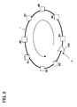
- Fig. 2 is a diagram for describing an embodiment according to the present invention.
- An embodiment according to the present invention is characterized in that (1) an optical amplifier 100 is provided within a transmission ring including an optical transmission line 1 connected in a ring. Furthermore, (2) optical signal powers inserted from each node apparatus are set so that the powers are substantially the same at the input A of the optical amplifier 100.
- all node apparatuses are not required to provide an optical amplifier for amplifying all optical signals within the transmission line.
- Fig. 3 is a diagram for describing the method for setting optical signal powers inserted from each node apparatus to be substantially the same at the input A of the optical amplifier 100.
- the horizontal axis represents the received powers of the optical signal sent from the other node apparatuses at each node apparatus corresponding to the transmission line distance.
- the lowest power level shown on the vertical axis denotes the input optical signal power of the optical amplifier 100, and by means of setting the powers of the optical signals inserted by each node apparatus, the input optical signal powers of the optical amplifier 100 are substantially the same.
- the optical signal is amplified to the maximum power and outputted, even the optical signal is inserted and sent by any node apparatus, as shown by the output power B of the optical amplifier 100.
- the optical amplifier 100 is provided between the node apparatuses #3 and #4 located at some midpoint in the transmission line 1. Therefore, in Fig. 3, as to the transmission distance shown on the horizontal axis, the distance of the node apparatus #3 is the shortest, and the node apparatus #4 is the longest. From this figure, it can be understood that the optical signal levels, even the optical signals inserted from the other node apparatuses, are set so that all the optical signal levels are substantially the same at the input of the optical amplifier 100.
- a linear crosstalk of 20 dB or higher can be satisfied, even if by using a normal filter, and the optical signal which should be extracted can be received.
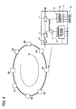
- Fig. 4 shows an altered example of the embodiment shown in Fig. 2, and in this configuration, any of the node apparatuses includes an optical amplifier 101, which is equivalent to the optical amplifier 100, placed at some midpoint in the optical transmission line 1.
- setting is made so that the levels of the optical signals inserted from each node apparatus are equal at the input of the optical amplifier 101 in the node apparatus, as described in Fig. 3.
- an optical signal generated and inserted by a laser diode 50 is amplified by an optical amplifier 51 to a specified level.
- the output of the optical amplifier 51 is inputted to an optical coupler 53, where optical signals having a wavelength to be inserted is further attenuated by a variable optical attenuator 52.
- optical signals having the wavelength to be inserted are combined together by the optical coupler 53 and sent out to the node apparatus on the next stage.
- the wavelength of the optical signal which is to be inserted by the node apparatus, can be set to any wavelength, by means of using a wavelength variable laser diode instead of the laser diode 50.
- an optical coupler 41 provided between a pre-amplifier 3 and optical filter 4 splits the received optical power into 4 corresponding to 4 wavelengths and inputs to the optical filter 4.
- the levels of the optical signals inserted from each node apparatus must be equal.
- the setting of the input power levels for the optical signals inserted by each node apparatus in order to meet the above-mentioned purpose can be made for each node apparatus when constructing a network.
- the input power level can be set adaptively by using a monitor control signal SV.
- Fig. 5 is a diagram showing a configuration of a node apparatus for controlling the input power level of the optical signals inserted by each node apparatus, by means of using the monitor control signal SV.
- a basic configuration of a node apparatus is the same as the node configuration shown in Fig. 4.
- the node configuration is characterized by comprising a separator circuit 13 for multi-separating an optical control signal (OSC) sent from the node apparatus on the previous stage provided on the input side, and a monitor signal (SV) processing circuit 15 for processing the optical control signal (OSC) extracted by the separator circuit 13.
- OSC optical control signal
- SV monitor signal
- an OSC insertion unit 14 is provided, for combining the optical control signal (OSC) outputted from the monitor signal (SV) processing circuit 15 with the optical signal which is wavelength division multiplexed by the optical coupler 5.
- the optical control signal (OSC) is separated from the wavelength division multiplexed optical signal to be inputted by the separator circuit 13 for multi-separating the optical control signal (OSC), and the separated optical control signal (OSC) is guided to the SV processing circuit 15.
- the SV processing circuit 15 detects a received power level notice for an optical signal from a node apparatus, where a path is pre-set by the inputted optical control signal (OSC) , and calculates a difference between a sending level of an optical signal to be inserted by the node apparatus and the informed received power level, so that a SV signal is generated for adjusting the sending level of the optical signal by a variable optical attenuator 52.
- OSC optical control signal
- the SV processing circuit 15 multiplexes the optical control signal (OSC) transferred from the previous stage with the output of the optical coupler 12, at the OSC insertion unit 14, and sends out to the node apparatuses on the next and later stages.
- OSC optical control signal
- a receiving signal amplifier 101, and an output amplifier 102 are provided, if required.
- Fig. 6 is a diagram for describing the adjustment of a sending power level for an optical signal having each channel wavelength inserted to both or either one of the output variable optical amplifier 51 or variable optical attenuator 52, by a SV signal generated by the SV processing circuit 15 in the node apparatus shown in Fig. 5.
- the output variable amplifier 51 or the variable optical attenuator 52 is provided corresponding to each wavelength to be generated and inserted by the laser diode 50, and the output powers of the output variable amplifier 51 and the variable attenuator 52 are set by a SV signal generated by the SV processing circuit 15.
- substantially the same received optical powers are obtained even if any optical paths are connected between node apparatuses in a ringed optical network.
- optical signals can be received stably, and the number of node apparatuses that can be introduced into the ring can be increased.
- the required optical output power for an optical amplifier in a node apparatus can be reduced, achieving a reduction in cost and size.
Landscapes
- Engineering & Computer Science (AREA)
- Computer Networks & Wireless Communication (AREA)
- Signal Processing (AREA)
- Computing Systems (AREA)
- Physics & Mathematics (AREA)
- Electromagnetism (AREA)
- Optical Communication System (AREA)
- Small-Scale Networks (AREA)
Abstract
Description
Claims (8)
- An optical ring network system comprising:wherein the sending power of optical signals to be inserted at each of the plurality of node apparatuses is set such that the received levels of the optical signals sent out from the plurality of node apparatuses and received at the input of the optical amplifier become equal.a plurality of node apparatuses each sending out wavelength division multiplexed optical signals;an optical transmission line connecting the plurality of node apparatuses in a ring; andat least one optical amplifier disposed on the optical transmission line;
- An optical ring network system comprising:wherein the sending power of optical signals to be inserted at each of the plurality of node apparatuses is set such that the received levels of the optical signals sent out from the plurality of node apparatuses and received at the input of the optical amplifier become equal.a plurality of node apparatuses each sending out wavelength division multiplexed optical signals;an optical transmission line connecting the plurality of node apparatuses in a ring; andan optical amplifier included in any of the plurality of node apparatuses, the optical amplifier being connected to the optical transmission line;
- The optical ring network system according to claim 2, whereineach of the plurality of node apparatuses includes control means for calculating a deviation and controlling the sending power of optical signals so that the calculated deviation becomes zero, the calculated deviation being the difference between the received optical signal level of a corresponding node apparatus connected via a path to the each of the plurality of node apparatuses, notified from the corresponding node apparatus, and the sending out level of the optical signal sent out.
- A node apparatus in an optical ring network which include a plurality of node apparatuses connected in a ring via an optical transmission line, the optical ring network having an optical relay amplifier disposed on a segment between the adjacent node apparatuses,
wherein the node apparatus comprises means for setting the sending power of optical signals to be inserted at each of the plurality of node apparatuses such that the receiving levels of the optical signals sent out from the plurality of node apparatuses and received at the input of the optical amplifier become equal. - A node apparatus in an optical ring network which include a plurality of node apparatuses connected in a ring via an optical transmission line, at least one of the plurality of node apparatuses having an optical relay amplifier connected to the optical transmission line,
wherein the node apparatus comprises means for setting the sending power of optical signals to be inserted at each of the plurality of node apparatuses such that the receiving levels of the optical signals sent out from the plurality of node apparatuses and received at the input of the optical amplifier become equal. - The node apparatus according to claim 4 or 5, wherein the wavelength of the wavelength division multiplexed optical signal is fixed.
- The node apparatus according to claim 4 or 5, wherein the wavelength of the wavelength division multiplexed optical signal is adaptively variable.
- The node apparatus according to claim 5, further comprising control means for calculating a deviation and controlling the sending power of optical signals so that the calculated deviation becomes zero, the calculated deviation being the difference between the received optical signal level of a corresponding node apparatus connected via a path thereto, notified from the corresponding node apparatus, and the sending out level of the optical signal sent out.
Applications Claiming Priority (2)
| Application Number | Priority Date | Filing Date | Title |
|---|---|---|---|
| JP2002170186 | 2002-06-11 | ||
| JP2002170186A JP4036687B2 (en) | 2002-06-11 | 2002-06-11 | An optical ring network system in which multiple node devices are connected in a ring shape |
Publications (2)
| Publication Number | Publication Date |
|---|---|
| EP1372281A2 true EP1372281A2 (en) | 2003-12-17 |
| EP1372281A3 EP1372281A3 (en) | 2005-02-09 |
Family
ID=29561750
Family Applications (1)
| Application Number | Title | Priority Date | Filing Date |
|---|---|---|---|
| EP03012187A Withdrawn EP1372281A3 (en) | 2002-06-11 | 2003-06-04 | Optical ring network system having a plurality of node apparatuses connected in a ring |
Country Status (3)
| Country | Link |
|---|---|
| US (1) | US20030228148A1 (en) |
| EP (1) | EP1372281A3 (en) |
| JP (1) | JP4036687B2 (en) |
Cited By (2)
| Publication number | Priority date | Publication date | Assignee | Title |
|---|---|---|---|---|
| FR2866765A1 (en) * | 2004-02-23 | 2005-08-26 | Cit Alcatel | RING OPTICAL TRANSMISSION NETWORK |
| EP1686715A1 (en) * | 2005-01-31 | 2006-08-02 | Fujitsu Ltd. | Optical network system and transmission apparatus |
Families Citing this family (4)
| Publication number | Priority date | Publication date | Assignee | Title |
|---|---|---|---|---|
| US7050669B2 (en) * | 2001-04-30 | 2006-05-23 | Trex Enterprises Corp. | Optical cross connect switch with axial alignment beam |
| WO2006006215A1 (en) * | 2004-07-09 | 2006-01-19 | Fujitsu Limited | Optical circuit, linear system dedicated node apparatus using the same, linear system wdm network, and tree system wdm network |
| WO2006030524A1 (en) | 2004-09-17 | 2006-03-23 | Fujitsu Limited | Light adding/dropping device |
| JP6094294B2 (en) * | 2013-03-21 | 2017-03-15 | 沖電気工業株式会社 | Optical node |
Family Cites Families (21)
| Publication number | Priority date | Publication date | Assignee | Title |
|---|---|---|---|---|
| EP0452895B1 (en) * | 1990-04-18 | 1996-07-03 | Canon Kabushiki Kaisha | Optical communication network system and communication method using the same |
| JPH05196890A (en) * | 1992-01-22 | 1993-08-06 | Nec Corp | Optical isolator |
| US5345332A (en) * | 1993-05-03 | 1994-09-06 | Bell Communications Research, Inc. | Fiber amplifier cascade for multiwavelength lightwave communications system |
| GB9617396D0 (en) * | 1996-08-19 | 1996-10-02 | Stc Submarine Systems Ltd | Improvements in or relating to optical add/drop wavelength division multiplex systems |
| JPH10112700A (en) * | 1996-10-04 | 1998-04-28 | Nec Corp | Wavelength division multiplex transmitter of ring configuration |
| JPH11331127A (en) * | 1998-05-19 | 1999-11-30 | Fujitsu Ltd | Wavelength division multiplexing system and its terminal station |
| US6509986B1 (en) * | 1999-02-26 | 2003-01-21 | Ciena Corporation | WDM ring transmission system having amplified dropped channels |
| US6236499B1 (en) * | 1999-04-15 | 2001-05-22 | Nortel Networks Limited | Highly scalable modular optical amplifier based subsystem |
| US6542650B2 (en) * | 1999-11-30 | 2003-04-01 | University Of Southern California | Polarization-mode dispersion emulator |
| US6400479B1 (en) * | 1999-12-20 | 2002-06-04 | Sycamore Networks, Inc. | Optical power balancer for optical amplified WDM networks |
| US6417948B1 (en) * | 1999-12-24 | 2002-07-09 | Corning Incorporated | Variable delay device for an optical component such as a polarization mode dispersion compensator |
| US6567167B1 (en) * | 2000-02-16 | 2003-05-20 | Massachusetts Institute Of Technology | Compensating polarization mode dispersion in fiber optic transmission system |
| WO2001082516A1 (en) * | 2000-04-24 | 2001-11-01 | Lucent Technologies Inc. | Gain equalization in dwdm networks |
| US6961525B2 (en) * | 2000-11-17 | 2005-11-01 | Sycamore Networks, Inc. | Method for channel balance |
| US6721509B2 (en) * | 2000-12-05 | 2004-04-13 | Avanex Corporation | Self-adjusting optical add-drop multiplexer and optical networks using same |
| US7110676B2 (en) * | 2001-02-13 | 2006-09-19 | Tellabs Operations, Inc. | Power pre-emphasis for WDM transmission systems |
| WO2002080428A2 (en) * | 2001-03-29 | 2002-10-10 | Atoga Systems, Inc. | Open ring architectures for optical wdm networks |
| TW550409B (en) * | 2001-06-07 | 2003-09-01 | Ind Tech Res Inst | Optical signal interlace de-multiplexer |
| EP1394976A1 (en) * | 2002-08-30 | 2004-03-03 | Alcatel | Channel power control method in WDM system |
| US7027198B2 (en) * | 2003-08-08 | 2006-04-11 | General Photonics Corporation | Generation and analysis of state of polarization using tunable optical polarization rotators |
| US7218436B2 (en) * | 2003-08-08 | 2007-05-15 | General Photonics Corporation | Optical instrument and measurements using multiple tunable optical polarization rotators |
-
2002
- 2002-06-11 JP JP2002170186A patent/JP4036687B2/en not_active Expired - Fee Related
-
2003
- 2003-05-29 US US10/447,274 patent/US20030228148A1/en not_active Abandoned
- 2003-06-04 EP EP03012187A patent/EP1372281A3/en not_active Withdrawn
Cited By (5)
| Publication number | Priority date | Publication date | Assignee | Title |
|---|---|---|---|---|
| FR2866765A1 (en) * | 2004-02-23 | 2005-08-26 | Cit Alcatel | RING OPTICAL TRANSMISSION NETWORK |
| EP1569369A1 (en) * | 2004-02-23 | 2005-08-31 | Alcatel | Optical ring network |
| US7389047B2 (en) | 2004-02-23 | 2008-06-17 | Alcatel | Optical ring transmission network |
| EP1686715A1 (en) * | 2005-01-31 | 2006-08-02 | Fujitsu Ltd. | Optical network system and transmission apparatus |
| CN1815932B (en) * | 2005-01-31 | 2010-05-12 | 富士通株式会社 | Optical Network System and Transmission Device |
Also Published As
| Publication number | Publication date |
|---|---|
| JP2004015729A (en) | 2004-01-15 |
| JP4036687B2 (en) | 2008-01-23 |
| US20030228148A1 (en) | 2003-12-11 |
| EP1372281A3 (en) | 2005-02-09 |
Similar Documents
| Publication | Publication Date | Title |
|---|---|---|
| EP1183801B1 (en) | A highly scalable modular optical amplifier based subsystem | |
| EP0908034B1 (en) | Optical transmission systems using optical amplifiers and wavelength division multiplexing | |
| JP3821920B2 (en) | Optical communication system | |
| US5742416A (en) | Bidirectional WDM optical communication systems with bidirectional optical amplifiers | |
| KR101364960B1 (en) | Bidirectional optical amplifier array | |
| US8204379B2 (en) | Noise reduction in optical communications networks | |
| JP4256910B2 (en) | Optical network and protection switching method | |
| EP1265451A2 (en) | Architecture for a photonic transport network | |
| KR100334432B1 (en) | Bidirectional add / drop optical amplifier module using one waveguide thermal lattice multiplexer | |
| US6449072B1 (en) | Add/drop multiplexer | |
| JP4598528B2 (en) | Optical network and node for optical network | |
| EP1246378B1 (en) | A modular bidirectional optical amplification system | |
| US6785472B1 (en) | Broadband amplified WDM ring | |
| EP1630992A2 (en) | System and method for modularly scalable architecture for optical networks | |
| EP1372281A2 (en) | Optical ring network system having a plurality of node apparatuses connected in a ring | |
| JP2002016550A (en) | Optical amplifier | |
| US20040179846A1 (en) | Per-channel optical amplification using saturation mode | |
| JP3149916B2 (en) | WDM optical repeater | |
| EP1249956A2 (en) | In-line hub amplifier structure | |
| WO2003094398A1 (en) | Optical transport system architecture for remote terminal connectivity | |
| US20240305914A1 (en) | Wavelength conversion apparatus, optical transmission apparatus, and wavelength conversion method | |
| JP2010074678A (en) | Optical transmission system and optical transmission network system | |
| EP1511199B1 (en) | Method and system for controlling an amplifier in an optical network | |
| JP2003512795A (en) | Optical wavelength multiplexing device and WDM optical telecommunication system |
Legal Events
| Date | Code | Title | Description |
|---|---|---|---|
| PUAI | Public reference made under article 153(3) epc to a published international application that has entered the european phase |
Free format text: ORIGINAL CODE: 0009012 |
|
| AK | Designated contracting states |
Kind code of ref document: A2 Designated state(s): AT BE BG CH CY CZ DE DK EE ES FI FR GB GR HU IE IT LI LU MC NL PT RO SE SI SK TR |
|
| AX | Request for extension of the european patent |
Extension state: AL LT LV MK |
|
| PUAL | Search report despatched |
Free format text: ORIGINAL CODE: 0009013 |
|
| AK | Designated contracting states |
Kind code of ref document: A3 Designated state(s): AT BE BG CH CY CZ DE DK EE ES FI FR GB GR HU IE IT LI LU MC NL PT RO SE SI SK TR |
|
| AX | Request for extension of the european patent |
Extension state: AL LT LV MK |
|
| 17P | Request for examination filed |
Effective date: 20050714 |
|
| AKX | Designation fees paid |
Designated state(s): DE FR GB |
|
| GRAP | Despatch of communication of intention to grant a patent |
Free format text: ORIGINAL CODE: EPIDOSNIGR1 |
|
| STAA | Information on the status of an ep patent application or granted ep patent |
Free format text: STATUS: THE APPLICATION IS DEEMED TO BE WITHDRAWN |
|
| 18D | Application deemed to be withdrawn |
Effective date: 20061013 |