EP1372108B1 - Method for antiscatter stationary grid artifacts detection and attenuation in digital radiographic images - Google Patents
Method for antiscatter stationary grid artifacts detection and attenuation in digital radiographic images Download PDFInfo
- Publication number
- EP1372108B1 EP1372108B1 EP20030075307 EP03075307A EP1372108B1 EP 1372108 B1 EP1372108 B1 EP 1372108B1 EP 20030075307 EP20030075307 EP 20030075307 EP 03075307 A EP03075307 A EP 03075307A EP 1372108 B1 EP1372108 B1 EP 1372108B1
- Authority
- EP
- European Patent Office
- Prior art keywords
- grid
- image
- convolution
- frequency
- digital radiographic
- Prior art date
- Legal status (The legal status is an assumption and is not a legal conclusion. Google has not performed a legal analysis and makes no representation as to the accuracy of the status listed.)
- Expired - Lifetime
Links
Images


Classifications
-
- G—PHYSICS
- G06—COMPUTING OR CALCULATING; COUNTING
- G06T—IMAGE DATA PROCESSING OR GENERATION, IN GENERAL
- G06T5/00—Image enhancement or restoration
- G06T5/70—Denoising; Smoothing
-
- A—HUMAN NECESSITIES
- A61—MEDICAL OR VETERINARY SCIENCE; HYGIENE
- A61B—DIAGNOSIS; SURGERY; IDENTIFICATION
- A61B6/00—Apparatus or devices for radiation diagnosis; Apparatus or devices for radiation diagnosis combined with radiation therapy equipment
- A61B6/52—Devices using data or image processing specially adapted for radiation diagnosis
- A61B6/5211—Devices using data or image processing specially adapted for radiation diagnosis involving processing of medical diagnostic data
- A61B6/5252—Devices using data or image processing specially adapted for radiation diagnosis involving processing of medical diagnostic data removing objects from field of view, e.g. removing patient table from a CT image
-
- G—PHYSICS
- G06—COMPUTING OR CALCULATING; COUNTING
- G06T—IMAGE DATA PROCESSING OR GENERATION, IN GENERAL
- G06T5/00—Image enhancement or restoration
- G06T5/10—Image enhancement or restoration using non-spatial domain filtering
-
- G—PHYSICS
- G06—COMPUTING OR CALCULATING; COUNTING
- G06T—IMAGE DATA PROCESSING OR GENERATION, IN GENERAL
- G06T2207/00—Indexing scheme for image analysis or image enhancement
- G06T2207/10—Image acquisition modality
- G06T2207/10116—X-ray image
-
- G—PHYSICS
- G06—COMPUTING OR CALCULATING; COUNTING
- G06T—IMAGE DATA PROCESSING OR GENERATION, IN GENERAL
- G06T2207/00—Indexing scheme for image analysis or image enhancement
- G06T2207/20—Special algorithmic details
- G06T2207/20048—Transform domain processing
- G06T2207/20056—Discrete and fast Fourier transform, [DFT, FFT]
-
- G—PHYSICS
- G06—COMPUTING OR CALCULATING; COUNTING
- G06T—IMAGE DATA PROCESSING OR GENERATION, IN GENERAL
- G06T2207/00—Indexing scheme for image analysis or image enhancement
- G06T2207/30—Subject of image; Context of image processing
- G06T2207/30004—Biomedical image processing
Definitions
- This invention relates in general to digital medical imaging, and specifically to the presentation of digital projection radiography images for improved image quality and elimination of grid artifacts.
- the detected radiation field contains both primary and secondary (scattered) components.
- Scattered X-rays reduce the contrast of images.
- Antiscatter grids absorb scattered radiation and increase image contrast.
- Devices that hold grids and X-ray film are known as "Bucky" from the name of Gustav Bucky, who first designed stationary grids in 1913 in Germany, and patented them in the USA, U.S. Patent no. 1,164,987, issued December 21, 1915. At the present time both stationary and moving grids are used for this purpose.
- the disadvantage of stationary grids is that they create line artifacts on film and digital images and, when changed in size for display or reprinting, create visible Moiré patterns due to spatial aliasing.
- Moving grids effectively remove the stripe artifacts by means of temporal blur.
- the various stationary grid designs including parallel, focused, and crossed, the most commonly used are linear grids with parallel stripes in one direction.
- Crossed grids have grid stripes in both orthogonal directions and are used less frequently.
- the most important features of a linear grid are its resolution in line/mm (millimeter) and the ratio between grid stripes height and distance. Due to the spatial regularity of the grids in one direction, strengthened by geometrical cut-off effect, the stripe artifacts in digital radiographic images can be considered as 1-D coherent spatial noise of a frequency corresponding to the distance between stripes.
- a method for grid linear artifact detection is proposed based on 2-D dynamic correlation in both spatial and frequency domains. This method provides results including grid orientation, frequency, and SNR.
- a 1-D frequency bandstop (notch) filter is known as the best instrument for narrow-banded noise elimination.
- notch filter design and implementation are known (see: Hamming R. W. "Digital filters", Englewood Cliffs, NJ: Prentice-Hall, 1985).
- filter transfer function parameters to tune, including cut frequency, bandwidth, attenuation level, and Gibbs event amplitudes.
- a method of 1-D frequency bandstop filter is proposed as the method that best corresponds to the noise nature of the grid artifact, for the purpose of removing both grid line artifacts and Moiré patterns, which are very noticeable when a softcopy image display is resized.
- a detection algorithm is based on a dynamic analysis of autocorrelation and cross-correlation functions 1 st derivative spectra calculated in a defined square region within the image in each of two dimensions. It provides grid frequency, SNR and orientation.
- a digital 1-D frequency bandstop filter is automatically designed as a function of detected grid frequency and SNR. This filter is then applied to the input image in the direction orthogonal to the detected grid orientation.
- the invention has the following advantages.
- the method of the present invention is described as a series of operations performed on a digital image, such as a digital radiographic image of a body part.
- the digital image can be formed by the digital image acquisition system of Fig. 10.
- x-ray source 200 projects x-rays through object 202 (such as a body part extremity, e.g., hand or foot) to image acquisition system 204.
- the image acquisition system can be, for example, (1) a standard x-ray screen/film combination which produces an x-ray film image which is processed chemically or thermally and the processed film digitized by a scanner/digitizer 206; (2) a computed radiography system where a latent x-ray image is formed in a storage phosphor 204 and a corresponding digital image is produced by reading out the storage phosphor by a CR reader 206; (3) a diagnostic scanner (such as MRI, CT, US, PET) produces an electronic x-ray image which is digitized; and (4) a direct digital acquisition system typically consisting of a phosphor based scintillating screen coupled to an imager (CCD, MOS) through a lens or fiber optic system.
- image processor 208 can take the form of a digital computer, such as illustrated in Fig. 11. In such case, one or more of the steps of said method can be carried out using software routines. Image processor 208 can also include hardware or firmware for carrying out one or more of said method steps. Thus, the steps of the method of the invention can be carried out using software, firmware, and hardware, either alone or in any preferable combination.
- a digital computer 300 includes a memory 310 for storing digital images, application programs, operating system, etc.
- Memory 310 can include mass memory (such as a hard magnetic disc or CD ROM), and fast memory (such as RAM).
- Computer 300 also includes input device 312 (such as a keyboard, mouse, touch screen), display 314 (CRT monitor, LCD), central processing unit 316 (microprocessor), output device 318 (thermal printer, dot matrix printer, laser printer, ink jet printer).
- Components 310, 312, 314, 316, 318 are connected together by control/data bus 320.
- Computer 300 can include a transportable storage medium drive 322 for reading from and/or writing to transportable storage media 324 , such as a floppy magnetic disk or writeable optical compact disk (CD).
- transportable storage media 324 such as a floppy magnetic disk or writeable optical compact disk (CD).
- computer readable storage medium can include, specifically, memory 310 and transportable storage medium 324. More generally, computer storage medium may comprise, for example, magnetic storage media, such as magnetic disk (hard drive, floppy disk) or magnetic tape; optical storage media, such as optical disk, optical tape, or machine readable bar code; solid state electronic storage devices, such as random access memory (RAM), read only memory (ROM); or any other physical device or medium which can be employed to store a computer program.
- magnetic storage media such as magnetic disk (hard drive, floppy disk) or magnetic tape
- optical storage media such as optical disk, optical tape, or machine readable bar code
- solid state electronic storage devices such as random access memory (RAM), read only memory (ROM); or any other physical device or medium which can be employed to store a computer program.
- the present invention provides a method for improving projection radiographic images which contain stationary grids.
- the present invention includes a method of detecting the grids that can be used alone or in combination with a method of suppressing the grids from the radiographic image to improve image quality.
- the detecting and suppressing method of the present invention can be applied more broadly to detect a pattern of lines in a digital image and to suppress a detected pattern of lines to improve image quality.
- Fig. 9 is a block diagram of the general method of the present invention: an input digital radiographic image is provided (box 10).
- the image is processed with the grid artifacts detecting algorithm (box 12) to detect a grid in the image (diamond 14). If a grid is detected, the grid artifacts are suppressed by processing the image with the grid suppression algorithm of the invention (box 16). A grid suppressed output digital radiographic image is thereby produced (box 18). If no grid is detected, (diamond 14) the output image (box 18) is the same as the input image (box 10).
- Fig. 9 can be applied more broadly to any digital image which can have a pattern of lines.
- a digital image would be provided (box 10)
- the line detection algorithm would be applied to the input digital image to detect a pattern of lines in the input image (diamond 14). If it is desired to suppress the pattern of lines, if detected, the line suppression algorithm is applied to the input image (box 16) to produce an output digital image free of the lines (box 18).
- method of the present invention comprises two main algorithms -- detection and attenuation - and each of them consists of sequence of operations performed on digital radiographic images to detect and to eliminate grid artifacts (see block diagram in Fig. 1).
- an image is captured in CR or DR system, digitized from a film, or retrieved from an image archive (box 20), it is stored in workstation memory (box 22). Then the image is analyzed by a grid detector algorithm (box 24). If no grid is detected (diamond 26), no grid suppression image processing is applied, and the output image (box 29) will be the same as input one.
- the grid detection algorithm proposed in the present invention consists of several steps (see block diagram in Fig. 2).
- the predefined numbers for analysis are: the size and location of a square region of the image in the spatial pixel domain (called “window” below), the increment step dS as a profile number, and the required grid peak search accuracy dF in the frequency domain.
- Linear window size (LWS) is defined as a power of 2 nearest to the half of smallest image size known as width and height.
- the window may be positioned in any of the 4 image corners, beginning from the image edges, where grid artifacts are usually strengthened by the geometrical cut-off effect.
- the step dS 1% of LWS .
- the accuracy dF 1% of Nyquist frequency.
- a loop is initiated for each of the horizontal and vertical directions sequentially for a number of profiles N win in the defined window with increment dS .
- the loop comprises several operations:
- the described grid artifact detection algorithm provides grid orientation, frequency and SNR as a set of parameters necessary and sufficient for the automatic design of a frequency notch filter algorithm which is used for artifact suppression, also proposed in the present invention.
- the statistical and spectral fundamentals of the proposed detection algorithm are the following.
- the human eyes and brain correlate spatial patterns simultaneously in each of the two spatial dimensions.
- the image profiles can be considered as an ensemble of realizations of a stochastic process.
- the auto-correlation function (ACF) and its spectrum characterize periodic processes in 1-D.
- the ACF has the same frequency spectrum but more smoothed one compare to the image profile spectrum.
- the cross-correlation function (CCF) and its frequency spectrum of 2 image profiles characterize the relation between them in the direction orthogonal to ACF.
- CCF has more smoothed spectrum similar to ACF for stationary processes with a coherent noise. Matching the ACF and CCF frequency peaks reveals the presence of 1-D spatial noise. Therefore, the combination of such statistical spatial and frequency analysis gives a 2-D correlation.
- Dynamic tracking of detection success is the measure of algorithm robustness and is close to 100% in the presence of the grid and is close to 0% else, as tested.
- the intermediate computation of ACF and CCF 1 st derivatives described in steps 3 and 4 above helps to remove the influence of low frequency trends in frequency spectra of those functions.
- the numerical techniques at each of the steps above are well known (see: Fuller W. A. "Introduction to Statistical Time Series", 2nd Edition, Wiley, John & Sons, Incorporated, 1995).
- Grid artifact attenuation algorithm proposed in the present invention comprises several procedures. If grid was detected and its orientation and frequency are known then a digital 1-D notch filter is designed as a function of grid frequency and attenuation level. Different algorithms for notch filter design and implementation are known (see: Hamming R. W. "Digital filters", Englewood Cliffs, NJ: Prentice-Hall, 1985). The goal here is to choose the filter that maximizes the suppression of grid artifacts with minimal image distortion. Both factors mentioned above depend on filter transfer function features such as attenuation level and Gibbs event amplitudes respectively. Attenuation level in its turn depends on filter operator length and bandwidth.
- the Potter finite impulse response trigonometric trapezoidal filter algorithm (see: Potter R. W. "Compilation of time windows and time shapes for Fourier analysis", 02-5952-0705, Hewlett-Packard, 1971) is proposed as one of the best candidates for the optimal implementation of the notch filter transfer function.
- b kn a kn p k
- Attenuation levels can be adjusted using 2 filter parameters: half of the operator length in a range of 24-32 coefficients and rejection bandwidth in a range of 0.07-0.1 as a fraction of Nyquist frequency.
- attenuation steps can be designed as a user-selectable option within a range of about -20 dB to -60 dB with increment of -3 to -4 dB.
- Automatic selection of attenuation level is based on grid peak SNR revealed by the detector. The preferred (default) value can be set up manually for the appropriate attenuation of grid artifacts for a specific CR/DR modality image.
- filter algorithm implementations are Chebysheb filter of type II, and Kaiser filter (see: Hamming R.W. "Digital filters", Englewood Cliffs, NJ: Prentice-Hall, 1985).
- FIG. 3 box 70 After digital filter is designed (Fig. 3, box 70), there is a loop for image profiles filtering: horizontal or vertical image profiles are input (box 72), pre-convolution, fast convolution, and post convolution procedures are applied (boxes 74, 76, 78) to each image profile to produce an output image profile (box 82).
- Filtering is based on 1-D spatial domain convolution of filter coefficients, with each of N horizontal or vertical (or both for crossed grids) image profile, depending on grid orientation and configuration. N is equal to total number of horizontal or vertical profiles in a specific image.
- the traditional method of convolution is well known in the art of digital image processing (see: Hamming R. W. "Digital filters", Englewood Cliffs, NJ: Prentice-Hall, 1985).
- a pre-convolution and post-convolution procedures (Fig 3, boxes 74, 78) are proposed for filter edge and spikes effects elimination.
- Edge effect is visible line artifact with a length of M equal to half of filter operator length caused by its convolution with a number of pixel values containing big and sharp change in intensity of one sign or simply the end of pixel series at image edge.
- Spike effect is a noticeable line artifact caused by filter weights convolution with extremely high and narrow peak in intensity. Those spikes might be originated by bad pixels in CR/DR screens/detectors or by possible their damage.
- a pre-convolution procedure (see: block diagram in Fig. 4) consists of 2 main steps.
- each input (box 84) image profile is extended at its both ends (box 88) by replicating M times first and last profile value respectively, for filter edge effect elimination purpose.
- each image profile is analyzed by spike detection and processing function (box 86). Fast convolution is then effected (box 90).
- the spike detection algorithm proposed in the present invention performs spike detection, retaining the values of detected spikes, and substituting the values of such spikes with linearly interpolated neighbor values.
- Spikes detection is based on statistical thresholding approach.
- An input image profile is considered as a smooth continuous function defined on the image profile interval except for some predefined number of values at image edges.
- the spike detection threshold is defined as a mean square value of the first derivative of that function.
- the values of a differentiated profile are compared with a calculated threshold. If they exceed it and are 3 or fewer pixels wide, the corresponding intensity values in the image profile are treated as spikes. Then spike values and positions are stored in a memory buffer, and their values are substituted with linear interpolated neighbor values.
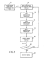
- a post-convolution procedure comprises 2 steps with the inverse functions of the pre-convolution procedure functions (see: block diagram in Fig. 5).
- first step after fast convolution has been effected box 92
- the memorized spikes are returned back to their original positions if they are considered clinically valuable. If not, they are not restored, i.e. they are eliminated (box 96).
- the latter choice might be useful for low quality images containing a lot of bright dots or scratches.
- the edge effect elimination is a mandatory function while spike processing function is optional defined by user.
- the output image profile results box 98). The method to determine if the spikes should be restored is not specified by this invention.
- the output image is stored in workstation memory (see: block diagram in Fig. 1). After that the image might be displayed, printed, transmitted, and/or stored in image archive.
- Figs. 6A-6C illustrate respective averaged Fourier spectra of a CR image profile, containing grid peaks
- Figs. 7A and 7B respectively illustrate the CR image profile fragment and its corresponding Fourier spectrum with a visible grid peak.
- Figs. 8A and 8B respectively illustrate the filtered CR image profile fragment of Fig. 7A and its corresponding Fourier spectrum demonstrating the attenuation of the grid peak.
Landscapes
- Engineering & Computer Science (AREA)
- Physics & Mathematics (AREA)
- Health & Medical Sciences (AREA)
- Life Sciences & Earth Sciences (AREA)
- Medical Informatics (AREA)
- Theoretical Computer Science (AREA)
- General Physics & Mathematics (AREA)
- Biomedical Technology (AREA)
- Animal Behavior & Ethology (AREA)
- Optics & Photonics (AREA)
- Pathology (AREA)
- Radiology & Medical Imaging (AREA)
- High Energy & Nuclear Physics (AREA)
- Heart & Thoracic Surgery (AREA)
- Molecular Biology (AREA)
- Surgery (AREA)
- Nuclear Medicine, Radiotherapy & Molecular Imaging (AREA)
- General Health & Medical Sciences (AREA)
- Public Health (AREA)
- Veterinary Medicine (AREA)
- Biophysics (AREA)
- Computer Vision & Pattern Recognition (AREA)
- Image Processing (AREA)
- Apparatus For Radiation Diagnosis (AREA)
- Image Analysis (AREA)
Abstract
Description
- This invention relates in general to digital medical imaging, and specifically to the presentation of digital projection radiography images for improved image quality and elimination of grid artifacts.
- In projection radiography the detected radiation field contains both primary and secondary (scattered) components. Scattered X-rays reduce the contrast of images. Antiscatter grids absorb scattered radiation and increase image contrast. Devices that hold grids and X-ray film are known as "Bucky" from the name of Gustav Bucky, who first designed stationary grids in 1913 in Germany, and patented them in the USA, U.S. Patent no. 1,164,987, issued December 21, 1915. At the present time both stationary and moving grids are used for this purpose. The disadvantage of stationary grids is that they create line artifacts on film and digital images and, when changed in size for display or reprinting, create visible Moiré patterns due to spatial aliasing. Moving grids effectively remove the stripe artifacts by means of temporal blur. Of the various stationary grid designs, including parallel, focused, and crossed, the most commonly used are linear grids with parallel stripes in one direction. Crossed grids have grid stripes in both orthogonal directions and are used less frequently. The most important features of a linear grid are its resolution in line/mm (millimeter) and the ratio between grid stripes height and distance. Due to the spatial regularity of the grids in one direction, strengthened by geometrical cut-off effect, the stripe artifacts in digital radiographic images can be considered as 1-D coherent spatial noise of a frequency corresponding to the distance between stripes.
- In U.S. Patent no. 5,661,818, issued August 26, 1997, inventors Gaborski et. al., discloses a grid artifacts detection method which is based on a double auto-correlation calculation. Variances are measured independently, both horizontally and vertically and a statistical F test is performed to determine if the variances are the same over a randomly chosen sampling of locations within the image. Votes are then tallied and if a majority indicates that the variances are different, a decision is made in favor of a grid being present. This method, however, does not provide a key parameter - the grid line frequency - as well as other important grid features that might be useful in further suppression. Another method was proposed in U.S. Patent no. 6,269,176, issued July 31, 2001, inventors Barski et al. It is based on 1-D spectral approach and comprises several steps: finding a window for analysis, obtaining averaged 1-D Fourier power spectra in each direction, searching for the maxima in the right part of smoothed and morphologically filtered averaged spectra as grid peak candidates, collecting the attributes of each peak, sorting the candidates in terms of figure-of-merit (FOM), and picking the best candidate with the highest FOM. This method provides such grid peak attributes as orientation, frequency, magnitude, total energy, half-width of full maximum, coherency. Although these methods were suitable for the uses for which they were intended, the main disadvantage of both of these methods is the uncertainty in picking the right candidate if several frequencies are detected, due to the lack of dynamic tracking of success in the 1-D analysis. A second disadvantage is that neither method provides information about signal-to-noise ratio (SNR) in the frequency grid peak area, which is needed as a parameter for further automatic tuning and design of the attenuation filter.
- In the present invention a method for grid linear artifact detection is proposed based on 2-D dynamic correlation in both spatial and frequency domains. This method provides results including grid orientation, frequency, and SNR.
- A 1-D frequency bandstop (notch) filter is known as the best instrument for narrow-banded noise elimination. Several different algorithms for notch filter design and implementation are known (see: Hamming R. W. "Digital filters", Englewood Cliffs, NJ: Prentice-Hall, 1985). In order to maximize the suppression of grid artifacts and to minimize image distortion, there are several filter transfer function parameters to tune, including cut frequency, bandwidth, attenuation level, and Gibbs event amplitudes.
- The grid artifact suppression method proposed in U.S. Patent no. 6,269,176, issued July 31, 2001, inventors Barski et al., was based on 1-D adaptive gaussian blur filters design for use in the spatial domain. The principal disadvantage of that method is that Fourier transform of a gaussian filter is just a transfer function of a lowpass filter. It is very complicated to tune such a filter to the right cut frequency, i.e. grid peak frequency, and to compute this filter coefficients in the spatial domain. Moreover, the disadvantage of lowpass filter vs. a bandstop filter is that all frequencies higher than the one identified as the grid frequency in each specific gaussian filter are eliminated. This is the reason that such filters cause image blur, which in many cases may be unacceptable from a clinical point of view.
- In the present invention a method of 1-D frequency bandstop filter is proposed as the method that best corresponds to the noise nature of the grid artifact, for the purpose of removing both grid line artifacts and Moiré patterns, which are very noticeable when a softcopy image display is resized. There were no prior efforts found in the patent record to use a frequency notch filter to suppress grid artifacts.
- According to the present invention, there is provided a solution to the problems discussed above.
- According to a feature of the present invention, there is provided a method for grid line artifacts and Moiré patterns detection and suppression in digital radiographic images. A detection algorithm is based on a dynamic analysis of autocorrelation and
cross-correlation functions 1st derivative spectra calculated in a defined square region within the image in each of two dimensions. It provides grid frequency, SNR and orientation. A digital 1-D frequency bandstop filter is automatically designed as a function of detected grid frequency and SNR. This filter is then applied to the input image in the direction orthogonal to the detected grid orientation. - The invention has the following advantages.
- 1. The detection algorithm is more reliable in grid peak candidate estimation because of using second dimension for analysis with a measure of robustness.
- 2. The detection algorithm provides grid SNR along with frequency and orientation, i.e. a set of parameters necessary and sufficient to automatically design and apply the attenuation filter.
- 3. The frequency bandstop filter eliminates either grid line artifacts on magnified images and Moiré patterns on minified images without introducing clinically important blur.
- 4. The method of the invention provides improved digital radiography image quality.
- Fig. 1 is a block diagram illustrating the process flow for image input, processing, and output, including the proposed grid artifacts attenuation method.
- Fig. 2 is a block diagram illustrating the proposed grid linear artifact detection algorithm.
- Fig. 3 is a block diagram illustrating the proposed grid artifacts filtering algorithm.
- Fig. 4 is a block diagram illustrating the pre-convolution procedure steps.
- Fig. 5 is a block diagram illustrating the post-convolution procedure steps.
- Figs. 6A-6C illustrate averaged Fourier spectra of: A - CR image profile, containing grid peak; B - 1st derivative of the autocorrelation function; C - 1st derivative of the cross-correlation function.
- Figs. 7A and 7B illustrate the CR image profile fragment and its corresponding Fourier spectrum with a visible grid peak.
- Figs. 8A and 8B illustrate the filtered CR image profile fragment from Fig. 7 and its corresponding Fourier spectrum demonstrating the attenuation of the grid peak.
- Fig. 9 is a block diagram of an embodiment of the present invention.
- Fig. 10 is a block diagram of a digital radiographic image acquisition system.
- Fig. 11 is a block diagram of a digital processor for carrying out the method of the present invention.
- The method of the present invention is described as a series of operations performed on a digital image, such as a digital radiographic image of a body part. The digital image can be formed by the digital image acquisition system of Fig. 10. As shown,
x-ray source 200 projects x-rays through object 202 (such as a body part extremity, e.g., hand or foot) toimage acquisition system 204. The image acquisition system can be, for example, (1) a standard x-ray screen/film combination which produces an x-ray film image which is processed chemically or thermally and the processed film digitized by a scanner/digitizer 206; (2) a computed radiography system where a latent x-ray image is formed in astorage phosphor 204 and a corresponding digital image is produced by reading out the storage phosphor by aCR reader 206; (3) a diagnostic scanner (such as MRI, CT, US, PET) produces an electronic x-ray image which is digitized; and (4) a direct digital acquisition system typically consisting of a phosphor based scintillating screen coupled to an imager (CCD, MOS) through a lens or fiber optic system. - The digital image is processed in
image processor 208, according to the method of the present invention.Image processor 208 can take the form of a digital computer, such as illustrated in Fig. 11. In such case, one or more of the steps of said method can be carried out using software routines.Image processor 208 can also include hardware or firmware for carrying out one or more of said method steps. Thus, the steps of the method of the invention can be carried out using software, firmware, and hardware, either alone or in any preferable combination. - As shown in Fig. 11, a digital computer 300 includes a
memory 310 for storing digital images, application programs, operating system, etc.Memory 310 can include mass memory (such as a hard magnetic disc or CD ROM), and fast memory (such as RAM). Computer 300 also includes input device 312 (such as a keyboard, mouse, touch screen), display 314 (CRT monitor, LCD), central processing unit 316 (microprocessor), output device 318 (thermal printer, dot matrix printer, laser printer, ink jet printer).Components data bus 320. Computer 300 can include a transportablestorage medium drive 322 for reading from and/or writing totransportable storage media 324 , such as a floppy magnetic disk or writeable optical compact disk (CD). - As used in this application, computer readable storage medium can include, specifically,
memory 310 andtransportable storage medium 324. More generally, computer storage medium may comprise, for example, magnetic storage media, such as magnetic disk (hard drive, floppy disk) or magnetic tape; optical storage media, such as optical disk, optical tape, or machine readable bar code; solid state electronic storage devices, such as random access memory (RAM), read only memory (ROM); or any other physical device or medium which can be employed to store a computer program. - The present invention provides a method for improving projection radiographic images which contain stationary grids. The present invention includes a method of detecting the grids that can be used alone or in combination with a method of suppressing the grids from the radiographic image to improve image quality. The detecting and suppressing method of the present invention can be applied more broadly to detect a pattern of lines in a digital image and to suppress a detected pattern of lines to improve image quality.
- Fig. 9 is a block diagram of the general method of the present invention: an input digital radiographic image is provided (box 10). The image is processed with the grid artifacts detecting algorithm (box 12) to detect a grid in the image (diamond 14). If a grid is detected, the grid artifacts are suppressed by processing the image with the grid suppression algorithm of the invention (box 16). A grid suppressed output digital radiographic image is thereby produced (box 18). If no grid is detected, (diamond 14) the output image (box 18) is the same as the input image (box 10).
- The method of Fig. 9 can be applied more broadly to any digital image which can have a pattern of lines. In such application, a digital image would be provided (box 10), the line detection algorithm would be applied to the input digital image to detect a pattern of lines in the input image (diamond 14). If it is desired to suppress the pattern of lines, if detected, the line suppression algorithm is applied to the input image (box 16) to produce an output digital image free of the lines (box 18).
- In general, method of the present invention comprises two main algorithms -- detection and attenuation - and each of them consists of sequence of operations performed on digital radiographic images to detect and to eliminate grid artifacts (see block diagram in Fig. 1). As soon as an image is captured in CR or DR system, digitized from a film, or retrieved from an image archive (box 20), it is stored in workstation memory (box 22). Then the image is analyzed by a grid detector algorithm (box 24). If no grid is detected (diamond 26), no grid suppression image processing is applied, and the output image (box 29) will be the same as input one. If a grid is detected (diamond 26), then 1-D grid artifact suppression is performed in the direction orthogonal to the detected grid orientation (box 30), and the output image (box 28) is the result of the image processing. Finally, the output image may be displayed, printed to film or paper or other media, transmitted to another computer system, or stored in a digital archive (box 32).
- The grid detection algorithm proposed in the present invention consists of several steps (see block diagram in Fig. 2). The predefined numbers for analysis are: the size and location of a square region of the image in the spatial pixel domain (called "window" below), the increment step dS as a profile number, and the required grid peak search accuracy dF in the frequency domain. Linear window size (LWS) is defined as a power of 2 nearest to the half of smallest image size known as width and height. The window may be positioned in any of the 4 image corners, beginning from the image edges, where grid artifacts are usually strengthened by the geometrical cut-off effect. The step dS=1% of LWS. The accuracy dF=1% of Nyquist frequency. Then a loop is initiated for each of the horizontal and vertical directions sequentially for a number of profiles N win in the defined window with increment dS. The loop comprises several operations:
- 1. Set initial values for profile numbers X=0, Y=dS, and detection success counter C=0 (box 40);
- 2.
Input 2 image profiles #X and #Y (box 42); - 3. Calculate an auto-correlation function for the profile X, take its 1st derivative, find maximum FMAX AC in the right part of its averaged Fourier power spectrum (high frequency), and store FMAX AC frequency (
box 44, box 46); - 4. Calculate a cross-correlation function for the X and Y profiles, take its 1st derivative, find maximum FMAX CC in the right part of its averaged Fourier power spectrum, and store FMAX CC frequency (
box 48, box 50); - 5. Compare if FMAX AC ≈ FMAX CC with accuracy dF (diamond 52); if they are not equal then increment profile numbers X=Y, Y=Y+dS and go to step 8 (diamond 54); if they are equal then increment a detection success counter C=C+1 and go to step 6 (box 56);
- 6. Obtain amplitude Fourier spectrum of profile X, then calculate a standard deviation σ of the signal frequencies within the bandwidth equal to accuracy dF at the frequency of 0.25 Nyquist (box 56);
- 7. Calculate signal-to-grid SNR as a ratio of σ and grid maximum magnitude detected within the bandwidth equal to accuracy dF at the frequency of FMAX CC , then store accumulated SNR value, and increment profile numbers X=Y, Y=Y+dS);
- 8. Check if Y does not exceed Nwin (diamond 54) then go to step 2 (box 42) else go to step 9 (diamond 60);
- 9. Check if detection success counter C exceeds 50% of total analyzed profiles number (diamond 60). If so, then go to step 11 (box 62) else go to step 10 (box 64);
- 10. Since a grid is not detected (box 64), the output image (box 66) is the same as input;
- 11. Since grid is detected in this direction obtain grid frequency as averaged frequency of FMAX CC matched with FMAX AC , and obtain averaged SNR value (box 62);
- 12. Perform the grid filtering operation on the image (below) (box 68).
- The described grid artifact detection algorithm provides grid orientation, frequency and SNR as a set of parameters necessary and sufficient for the automatic design of a frequency notch filter algorithm which is used for artifact suppression, also proposed in the present invention.
- The statistical and spectral fundamentals of the proposed detection algorithm are the following. The human eyes and brain correlate spatial patterns simultaneously in each of the two spatial dimensions. The image profiles can be considered as an ensemble of realizations of a stochastic process. The auto-correlation function (ACF) and its spectrum characterize periodic processes in 1-D. The ACF has the same frequency spectrum but more smoothed one compare to the image profile spectrum. The cross-correlation function (CCF) and its frequency spectrum of 2 image profiles characterize the relation between them in the direction orthogonal to ACF. CCF has more smoothed spectrum similar to ACF for stationary processes with a coherent noise. Matching the ACF and CCF frequency peaks reveals the presence of 1-D spatial noise. Therefore, the combination of such statistical spatial and frequency analysis gives a 2-D correlation. Dynamic tracking of detection success is the measure of algorithm robustness and is close to 100% in the presence of the grid and is close to 0% else, as tested. The intermediate computation of ACF and
CCF 1st derivatives described insteps - Grid artifact attenuation algorithm proposed in the present invention comprises several procedures. If grid was detected and its orientation
and frequency are known then a digital 1-D notch filter is designed as a function of grid frequency and attenuation level. Different algorithms for notch filter design and implementation are known (see: Hamming R. W. "Digital filters", Englewood Cliffs, NJ: Prentice-Hall, 1985). The goal here is to choose the filter that maximizes the suppression of grid artifacts with minimal image distortion. Both factors mentioned above depend on filter transfer function features such as attenuation level and Gibbs event amplitudes respectively. Attenuation level in its turn depends on filter operator length and bandwidth. - In the present invention the Potter finite impulse response trigonometric trapezoidal filter algorithm (see: Potter R. W. "Compilation of time windows and time shapes for Fourier analysis", 02-5952-0705, Hewlett-Packard, 1971) is proposed as one of the best candidates for the optimal implementation of the notch filter transfer function. The notch filter coefficients are calculated from 2 lowpass filters coefficients tuned on low f 1 and high f 2 cut frequencies, which are obtained from grid frequency f g and bandstop width B using:

- For each lowpass filter, rectangular filter transfer function coefficients are calculated using:


c k =½, if k = M,
c k = 1 ,if k ≠ M
c 0 = 2.8108034
d 0 ; = d 1 = 0.684988, d 2 = 0.202701, d 3 = 0.0177127; - Then bandstop filter coefficients are calculated using:

- Final notch filter operator coefficients are obtained by adding the left part coefficients symmetrical to the right ones calculated in (5) using:

- Attenuation levels can be adjusted using 2 filter parameters: half of the operator length in a range of 24-32 coefficients and rejection bandwidth in a range of 0.07-0.1 as a fraction of Nyquist frequency. Finally, attenuation steps can be designed as a user-selectable option within a range of about -20 dB to -60 dB with increment of -3 to -4 dB. Automatic selection of attenuation level is based on grid peak SNR revealed by the detector. The preferred (default) value can be set up manually for the appropriate attenuation of grid artifacts for a specific CR/DR modality image. Among other possible filter algorithm implementations are Chebysheb filter of type II, and Kaiser filter (see: Hamming R.W. "Digital filters", Englewood Cliffs, NJ: Prentice-Hall, 1985).
- After digital filter is designed (Fig. 3, box 70), there is a loop for image profiles filtering: horizontal or vertical image profiles are input (box 72),
pre-convolution, fast convolution, and post convolution procedures are applied (boxes output image 83 results. Filtering is based on 1-D spatial domain convolution of filter coefficients, with each of N horizontal or vertical (or both for crossed grids) image profile, depending on grid orientation and configuration. N is equal to total number of horizontal or vertical profiles in a specific image. The traditional method of convolution is well known in the art of digital image processing (see: Hamming R. W. "Digital filters", Englewood Cliffs, NJ: Prentice-Hall, 1985). - In this invention, a technique for the best convolution performance - the main time critical operation - is proposed based on known algorithms such as the "fast convolution" algorithm (see: Fuller W. A. "Introduction to Statistical Time Series", 2nd Edition, Wiley, John & Sons, Incorporated, 1995). This is generally possible with any computer platform, or may also be implemented using low-level vector algebra and math functions libraries for specific computer platforms such as Intel Signal Processing Library (see: Intel SPL, 2000) for Intel based computers. Using the proposed techniques the convolution performance can be improved by 4 to 10 times or more compare to a conventional convolution approach.
- In this invention a pre-convolution and post-convolution procedures (Fig 3,
boxes 74, 78) are proposed for filter edge and spikes effects elimination. Edge effect is visible line artifact with a length of M equal to half of filter operator length caused by its convolution with a number of pixel values containing big and sharp change in intensity of one sign or simply the end of pixel series at image edge. Spike effect is a noticeable line artifact caused by filter weights convolution with extremely high and narrow peak in intensity. Those spikes might be originated by bad pixels in CR/DR screens/detectors or by possible their damage. A pre-convolution procedure (see: block diagram in Fig. 4) consists of 2 main steps. At first step each input (box 84) image profile is extended at its both ends (box 88) by replicating M times first and last profile value respectively, for filter edge effect elimination purpose. At second step each
image profile is analyzed by spike detection and processing function (box 86). Fast convolution is then effected (box 90). - The spike detection algorithm proposed in the present invention performs spike detection, retaining the values of detected spikes, and substituting the values of such spikes with linearly interpolated neighbor values. Spikes detection is based on statistical thresholding approach. An input image profile is considered as a smooth continuous function defined on the image profile interval except for some predefined number of values at image edges. The spike detection threshold is defined as a mean square value of the first derivative of that function. The values of a differentiated profile are compared with a calculated threshold. If they exceed it and are 3 or fewer pixels wide, the corresponding intensity values in the image profile are treated as spikes. Then spike values and positions are stored in a memory buffer, and their values are substituted with linear interpolated neighbor values.
- A post-convolution procedure comprises 2 steps with the inverse functions of the pre-convolution procedure functions (see: block diagram in Fig. 5). In the first step after fast convolution has been effected (box 92), both ends of each extended filtered profile are removed to extract the profile with original length (box 94). In the second step the memorized spikes are returned back to their original positions if they are considered clinically valuable. If not, they are not restored, i.e. they are eliminated (box 96). The latter choice might be useful for low quality images containing a lot of bright dots or scratches. The edge effect elimination is a mandatory function while spike processing function is optional defined by user. The output image profile results (box 98). The method to determine if the spikes should be restored is not specified by this invention.
- When all image profiles have been filtered, the output image is stored in workstation memory (see: block diagram in Fig. 1). After that the image might be displayed, printed, transmitted, and/or stored in image archive.
- Figs. 6A-6C illustrate respective averaged Fourier spectra of a CR image profile, containing grid peaks;
- 1st derivative of the auto-correlation function; and
- 1st derivative of the cross-correlation function.
- Figs. 7A and 7B respectively illustrate the CR image profile fragment and its corresponding Fourier spectrum with a visible grid peak.
- Figs. 8A and 8B respectively illustrate the filtered CR image profile fragment of Fig. 7A and its corresponding Fourier spectrum demonstrating the attenuation of the grid peak.
Claims (9)
- A method for detecting and attenuating grid artifacts in a digital radiographic image comprising:providing an input digital radiographic image;processing said input digital radiographic image with a detection algorithm to determine whether said input digital radiographic image has grid artifacts; andif it does, then detecting grid characteristics of said grid artifacts;designing a notch filter as a function of said grid characteristics; andsuppressing said grid artifacts by further processing said input digital radiographic image with said designed notch filter to produce an output digital radiographic image of improved image quality,wherein said processing includes consequent dynamic analyzing image profiles in two dimensions both in spatial and in frequency domains in a predefined square sub-region of the input digital radiographic image in each of horizontal and vertical directions, andwherein said consequent dynamic analyzing includes calculating and analyzing auto-correlation (ACF) and cross-correlation (CCF) functions for 2 image profiles with predefined incremental step in said predefined square sub-region.
- The method of claim 1 wherein said analyzing of ACF and CCF includes the steps of:obtaining Fourier power spectra of ACF and CCF 1st derivatives;averaging the obtained Fourier power spectra;searching for the frequencies of the maxima in the right part of averaged Fourier spectra; andchecking that these frequencies of the maxima are the same values, within predefined accuracy.
- The method of claim 1 wherein said dynamic analyzing includes tracking successful matches of found frequency values treated as detected grid artifacts.
- The method of claim 1 wherein said detecting of grid characteristics includes detecting a grid frequency and maximum magnitude in a current image profile Fourier spectrum within the bandwidth equal to the predefined accuracy at the found frequency for CCF.
- The method of claim 1 wherein said detecting of grid characteristics includes detecting a grid signal-to-noise (SNR) ratio by the steps of:calculating a standard deviation of signal frequencies within the bandwidth equal to the predefined accuracy at the frequency of 0.25 of Nyquist;calculating and accumulating current image profile SNR as a ratio of said standard deviation and said grid maximum magnitude; andcalculating SNR averaged by total number of profiles with detected grid artifacts.
- The method of claim 1 wherein said detecting of grid characteristics includes detecting grid frequency by calculating the grid frequency from the frequencies of the maxima found in the right part of the CCF 1st derivative power spectrum, averaged over all image profiles that contain detected grid artifacts.
- The method of claim 1 wherein said designing includes:calculating finite impulse response notch filter coefficients, wherein said finite impulse response notch filter coefficients calculating includes using a trigonometric trapezoid filter algorithm with Potter P310 smoothing window; andwherein said step of suppressing includes using a spike effect elimination function and an edge effect elimination function.
- The method of claim 1, wherein said suppressing includes a pre-convolution procedure, a fast convolution procedure, and a post-convolution procedure;
wherein said pre-convolution and post-convolution procedures include using a spike effect elimination function and an edge effect elimination function; and
wherein said spike effect elimination function includes using a spike detection algorithm comprising the steps of:retaining spike locations and values until convolution is completed;substituting spike values with linear interpolated neighbor values; andoptionally replacing the spike values to their origin locations after convolution. - The method of claim 1, wherein said suppressing includes a pre-convolution procedure, a fast convolution procedure, and a post-convolution procedure;
wherein said pre-convolution and post-convolution procedures include using a spike effect elimination function and an edge effect elimination function; and
wherein said edge effect elimination function includes the steps of:(a) extending said image profile at both the ends to filter operator length by replicating first and last values at each end before said convolution; and(b) removing the extended image profile after said convolution.
Applications Claiming Priority (2)
| Application Number | Priority Date | Filing Date | Title |
|---|---|---|---|
| US68930 | 2002-02-08 | ||
| US10/068,930 US7050618B2 (en) | 2002-02-08 | 2002-02-08 | Method for antiscatter stationary grid artifacts detection and attenuation in digital radiographic images |
Publications (3)
| Publication Number | Publication Date |
|---|---|
| EP1372108A2 EP1372108A2 (en) | 2003-12-17 |
| EP1372108A3 EP1372108A3 (en) | 2004-05-19 |
| EP1372108B1 true EP1372108B1 (en) | 2006-08-30 |
Family
ID=27659131
Family Applications (1)
| Application Number | Title | Priority Date | Filing Date |
|---|---|---|---|
| EP20030075307 Expired - Lifetime EP1372108B1 (en) | 2002-02-08 | 2003-02-03 | Method for antiscatter stationary grid artifacts detection and attenuation in digital radiographic images |
Country Status (3)
| Country | Link |
|---|---|
| US (2) | US7050618B2 (en) |
| EP (1) | EP1372108B1 (en) |
| DE (1) | DE60307931T2 (en) |
Families Citing this family (83)
| Publication number | Priority date | Publication date | Assignee | Title |
|---|---|---|---|---|
| US7050618B2 (en) * | 2002-02-08 | 2006-05-23 | Eastman Kodak Company | Method for antiscatter stationary grid artifacts detection and attenuation in digital radiographic images |
| FR2841423A1 (en) * | 2002-06-25 | 2003-12-26 | Koninkl Philips Electronics Nv | METHOD FOR DETECTING BLOCK ARTEFACTS |
| US20050025381A1 (en) * | 2003-08-01 | 2005-02-03 | Munenori Oizumi | Image filter method |
| AU2006207953B2 (en) | 2005-01-28 | 2012-08-23 | The Regents Of The University Of California | Systems and methods using nuclear magnetic resonance (NMR) spectroscopy to evaluate pain and degenerative properties of tissue |
| DE602005018438D1 (en) * | 2005-02-24 | 2010-02-04 | Agfa Healthcare Nv | Method for checking the presence of a grid pattern in an X-ray image |
| US7479969B2 (en) * | 2005-02-24 | 2009-01-20 | Agfa Healthcare, N.V. | Grid detection method |
| US7826682B2 (en) * | 2005-04-14 | 2010-11-02 | Agfa Healthcare | Method of suppressing a periodical pattern in an image |
| US20060262902A1 (en) * | 2005-05-19 | 2006-11-23 | The Regents Of The University Of California | Security X-ray screening system |
| US7796792B2 (en) * | 2005-06-29 | 2010-09-14 | Agfa Healthcare, N.V. | Method of identifying disturbing frequencies originating from the presence of an anti-scatter grid during acquisition of a radiation image |
| DE102005037367B3 (en) * | 2005-08-08 | 2007-04-05 | Siemens Ag | Method for an X-ray device |
| US7889885B2 (en) * | 2005-11-23 | 2011-02-15 | Pitney Bowes Inc. | Method for detecting perforations on the edge of an image of a form |
| US9867530B2 (en) | 2006-08-14 | 2018-01-16 | Volcano Corporation | Telescopic side port catheter device with imaging system and method for accessing side branch occlusions |
| WO2008137804A1 (en) * | 2007-05-02 | 2008-11-13 | Feng Derek D | Quantum theory-based continuous precision nmr/mri: method and apparatus |
| US10219780B2 (en) | 2007-07-12 | 2019-03-05 | Volcano Corporation | OCT-IVUS catheter for concurrent luminal imaging |
| EP2178442B1 (en) | 2007-07-12 | 2017-09-06 | Volcano Corporation | Catheter for in vivo imaging |
| US9596993B2 (en) | 2007-07-12 | 2017-03-21 | Volcano Corporation | Automatic calibration systems and methods of use |
| EP2196148B1 (en) * | 2007-10-02 | 2015-03-04 | Shimadzu Corporation | Radiological image processing apparatus and radiological image processing program |
| US8825131B2 (en) | 2009-10-14 | 2014-09-02 | Nocimed, Llc | MR spectroscopy system and method for diagnosing painful and non-painful intervertebral discs |
| US8433154B2 (en) | 2010-12-13 | 2013-04-30 | Carestream Health, Inc. | Enhanced contrast for scatter compensation in X-ray imaging |
| US11141063B2 (en) | 2010-12-23 | 2021-10-12 | Philips Image Guided Therapy Corporation | Integrated system architectures and methods of use |
| US9968316B2 (en) | 2010-12-29 | 2018-05-15 | General Electric Company | High-frequency anti-scatter grid movement profile for line cancellation |
| US11040140B2 (en) | 2010-12-31 | 2021-06-22 | Philips Image Guided Therapy Corporation | Deep vein thrombosis therapeutic methods |
| US8761469B2 (en) * | 2011-01-03 | 2014-06-24 | Volcano Corporation | Artifact management in rotational imaging |
| JP5818475B2 (en) * | 2011-03-24 | 2015-11-18 | 富士フイルム株式会社 | Image processing apparatus, image processing method, and image processing program |
| WO2013033489A1 (en) | 2011-08-31 | 2013-03-07 | Volcano Corporation | Optical rotary joint and methods of use |
| JP2013172880A (en) * | 2012-02-27 | 2013-09-05 | Fujifilm Corp | Periodic pattern detection device and method |
| JP5753505B2 (en) * | 2012-02-28 | 2015-07-22 | 富士フイルム株式会社 | Periodic pattern detection apparatus and method |
| US8965094B2 (en) | 2012-04-14 | 2015-02-24 | Nocimed, Llc | Magnetic resonance spectroscopy pulse sequence, acquisition, and processing system and method |
| JP5821790B2 (en) * | 2012-06-27 | 2015-11-24 | 株式会社島津製作所 | X-ray diagnostic equipment |
| US10070827B2 (en) | 2012-10-05 | 2018-09-11 | Volcano Corporation | Automatic image playback |
| US9286673B2 (en) | 2012-10-05 | 2016-03-15 | Volcano Corporation | Systems for correcting distortions in a medical image and methods of use thereof |
| US9307926B2 (en) | 2012-10-05 | 2016-04-12 | Volcano Corporation | Automatic stent detection |
| US9324141B2 (en) | 2012-10-05 | 2016-04-26 | Volcano Corporation | Removal of A-scan streaking artifact |
| US10568586B2 (en) | 2012-10-05 | 2020-02-25 | Volcano Corporation | Systems for indicating parameters in an imaging data set and methods of use |
| US11272845B2 (en) | 2012-10-05 | 2022-03-15 | Philips Image Guided Therapy Corporation | System and method for instant and automatic border detection |
| US9858668B2 (en) | 2012-10-05 | 2018-01-02 | Volcano Corporation | Guidewire artifact removal in images |
| US9292918B2 (en) | 2012-10-05 | 2016-03-22 | Volcano Corporation | Methods and systems for transforming luminal images |
| US20140100454A1 (en) | 2012-10-05 | 2014-04-10 | Volcano Corporation | Methods and systems for establishing parameters for three-dimensional imaging |
| EP2904671B1 (en) | 2012-10-05 | 2022-05-04 | David Welford | Systems and methods for amplifying light |
| US9367965B2 (en) | 2012-10-05 | 2016-06-14 | Volcano Corporation | Systems and methods for generating images of tissue |
| US9840734B2 (en) | 2012-10-22 | 2017-12-12 | Raindance Technologies, Inc. | Methods for analyzing DNA |
| JP6322210B2 (en) | 2012-12-13 | 2018-05-09 | ボルケーノ コーポレイション | Devices, systems, and methods for targeted intubation |
| CA2895502A1 (en) | 2012-12-20 | 2014-06-26 | Jeremy Stigall | Smooth transition catheters |
| US11406498B2 (en) | 2012-12-20 | 2022-08-09 | Philips Image Guided Therapy Corporation | Implant delivery system and implants |
| WO2014107287A1 (en) | 2012-12-20 | 2014-07-10 | Kemp Nathaniel J | Optical coherence tomography system that is reconfigurable between different imaging modes |
| US10942022B2 (en) | 2012-12-20 | 2021-03-09 | Philips Image Guided Therapy Corporation | Manual calibration of imaging system |
| US10939826B2 (en) | 2012-12-20 | 2021-03-09 | Philips Image Guided Therapy Corporation | Aspirating and removing biological material |
| US9730613B2 (en) | 2012-12-20 | 2017-08-15 | Volcano Corporation | Locating intravascular images |
| US10058284B2 (en) | 2012-12-21 | 2018-08-28 | Volcano Corporation | Simultaneous imaging, monitoring, and therapy |
| CA2895993A1 (en) | 2012-12-21 | 2014-06-26 | Jason Spencer | System and method for graphical processing of medical data |
| WO2014100162A1 (en) | 2012-12-21 | 2014-06-26 | Kemp Nathaniel J | Power-efficient optical buffering using optical switch |
| EP2934280B1 (en) | 2012-12-21 | 2022-10-19 | Mai, Jerome | Ultrasound imaging with variable line density |
| US9612105B2 (en) | 2012-12-21 | 2017-04-04 | Volcano Corporation | Polarization sensitive optical coherence tomography system |
| US10413317B2 (en) | 2012-12-21 | 2019-09-17 | Volcano Corporation | System and method for catheter steering and operation |
| CA2895769A1 (en) | 2012-12-21 | 2014-06-26 | Douglas Meyer | Rotational ultrasound imaging catheter with extended catheter body telescope |
| US9486143B2 (en) | 2012-12-21 | 2016-11-08 | Volcano Corporation | Intravascular forward imaging device |
| WO2014099672A1 (en) | 2012-12-21 | 2014-06-26 | Andrew Hancock | System and method for multipath processing of image signals |
| US9383263B2 (en) | 2012-12-21 | 2016-07-05 | Volcano Corporation | Systems and methods for narrowing a wavelength emission of light |
| US10226597B2 (en) | 2013-03-07 | 2019-03-12 | Volcano Corporation | Guidewire with centering mechanism |
| CN113705586A (en) | 2013-03-07 | 2021-11-26 | 飞利浦影像引导治疗公司 | Multi-modal segmentation in intravascular images |
| US11154313B2 (en) | 2013-03-12 | 2021-10-26 | The Volcano Corporation | Vibrating guidewire torquer and methods of use |
| EP2967391A4 (en) | 2013-03-12 | 2016-11-02 | Donna Collins | SYSTEMS AND METHODS FOR DIAGNOSING CORONARY MICROVASCULAR DISEASE |
| CN105120759B (en) | 2013-03-13 | 2018-02-23 | 火山公司 | System and method for producing image from rotation intravascular ultrasound equipment |
| US9301687B2 (en) | 2013-03-13 | 2016-04-05 | Volcano Corporation | System and method for OCT depth calibration |
| US11026591B2 (en) | 2013-03-13 | 2021-06-08 | Philips Image Guided Therapy Corporation | Intravascular pressure sensor calibration |
| US20160030151A1 (en) | 2013-03-14 | 2016-02-04 | Volcano Corporation | Filters with echogenic characteristics |
| US12343198B2 (en) | 2013-03-14 | 2025-07-01 | Philips Image Guided Therapy Corporation | Delivery catheter having imaging capabilities |
| US10292677B2 (en) | 2013-03-14 | 2019-05-21 | Volcano Corporation | Endoluminal filter having enhanced echogenic properties |
| US10219887B2 (en) | 2013-03-14 | 2019-03-05 | Volcano Corporation | Filters with echogenic characteristics |
| CN104077743A (en) * | 2013-03-25 | 2014-10-01 | 深圳市蓝韵实业有限公司 | Suppression method and device for grid artifact in X-ray image |
| CN104574288B (en) * | 2013-10-22 | 2017-07-21 | 辽宁开普医疗系统有限公司 | A kind of adaptive grid artifact suppressing method and its device |
| CN105574816B (en) * | 2014-10-13 | 2021-03-30 | Ge医疗系统环球技术有限公司 | Method and device for eliminating grid shadow of X-ray image and X-ray machine upgrading kit |
| JP6929343B2 (en) * | 2015-06-30 | 2021-09-01 | キヤノン株式会社 | Image processing device and image processing method, image processing program |
| WO2017160829A1 (en) * | 2016-03-15 | 2017-09-21 | The Trustees Of Columbia University In The City Of New York | Method and apparatus to perform local de-noising of a scanning imager image |
| CN107203983B (en) | 2016-03-17 | 2024-03-22 | 通用电气公司 | Method and system for reducing grating artifacts in X-ray images |
| CN105832359B (en) * | 2016-03-22 | 2018-10-19 | 广州七喜医疗设备有限公司 | A kind of method of adaptive x-ray grid grid shadow removal |
| DE102016206559B3 (en) * | 2016-04-19 | 2017-06-08 | Siemens Healthcare Gmbh | Method for correcting an X-ray image for effects of a scattered radiation grid, X-ray device, computer program and electronically readable data carrier |
| EP3471608B1 (en) | 2016-06-19 | 2023-08-23 | Aclarion, Inc. | Magnetic resonance spectroscopy system and method for diagnosing pain or infection associated with propionic acid |
| KR102579457B1 (en) | 2017-02-24 | 2023-09-14 | 삼성전자주식회사 | Method and apparatus for correcting image |
| EP3692918B1 (en) | 2019-02-08 | 2021-05-19 | Siemens Healthcare GmbH | Learning-based correction of raster artefacts in x-ray imaging |
| JP7233251B2 (en) * | 2019-02-28 | 2023-03-06 | キヤノン株式会社 | Information processing device, control method and program for information processing device |
| US20220284556A1 (en) * | 2019-09-10 | 2022-09-08 | Carestream Health, Inc. | Confidence map for radiographic image optimization |
| US12039745B2 (en) | 2021-07-27 | 2024-07-16 | GE Precision Healthcare LLC | Method and systems for removing anti-scatter grid artifacts in x-ray imaging |
Family Cites Families (12)
| Publication number | Priority date | Publication date | Assignee | Title |
|---|---|---|---|---|
| US1164987A (en) | 1914-02-03 | 1915-12-21 | Siemens Ag | Method of and apparatus for projecting röntgen images. |
| US4792900A (en) | 1986-11-26 | 1988-12-20 | Picker International, Inc. | Adaptive filter for dual energy radiographic imaging |
| US5276614A (en) * | 1989-11-17 | 1994-01-04 | Picker International, Inc. | Dynamic bandwidth reconstruction |
| US5440647A (en) | 1993-04-22 | 1995-08-08 | Duke University | X-ray procedure for removing scattered radiation and enhancing signal-to-noise ratio (SNR) |
| JP3409220B2 (en) * | 1994-09-20 | 2003-05-26 | コニカ株式会社 | Image reading device |
| US5661818A (en) | 1995-01-27 | 1997-08-26 | Eastman Kodak Company | Method and system for detecting grids in a digital image |
| US6333990B1 (en) * | 1998-06-02 | 2001-12-25 | General Electric Company | Fourier spectrum method to remove grid line artifacts without changing the diagnostic quality in X-ray images |
| JP2000003440A (en) * | 1998-06-12 | 2000-01-07 | Fuji Photo Film Co Ltd | Moire removing filter and image processing method and device using the filter |
| US6233060B1 (en) * | 1998-09-23 | 2001-05-15 | Seiko Epson Corporation | Reduction of moiré in screened images using hierarchical edge detection and adaptive-length averaging filters |
| US6269176B1 (en) | 1998-12-21 | 2001-07-31 | Eastman Kodak Company | Method for x-ray antiscatter grid detection and suppression in digital radiography |
| DE60121639T2 (en) * | 2000-01-20 | 2007-07-26 | Fuji Photo Film Co., Ltd., Minami-Ashigara | Method and device for suppressing periodic noise |
| US7050618B2 (en) * | 2002-02-08 | 2006-05-23 | Eastman Kodak Company | Method for antiscatter stationary grid artifacts detection and attenuation in digital radiographic images |
-
2002
- 2002-02-08 US US10/068,930 patent/US7050618B2/en not_active Expired - Lifetime
-
2003
- 2003-02-03 EP EP20030075307 patent/EP1372108B1/en not_active Expired - Lifetime
- 2003-02-03 DE DE2003607931 patent/DE60307931T2/en not_active Expired - Fee Related
-
2005
- 2005-12-09 US US11/298,375 patent/US7174038B2/en not_active Expired - Lifetime
Also Published As
| Publication number | Publication date |
|---|---|
| DE60307931T2 (en) | 2007-05-10 |
| EP1372108A2 (en) | 2003-12-17 |
| US20060126912A1 (en) | 2006-06-15 |
| US7050618B2 (en) | 2006-05-23 |
| US7174038B2 (en) | 2007-02-06 |
| EP1372108A3 (en) | 2004-05-19 |
| US20030152259A1 (en) | 2003-08-14 |
| DE60307931D1 (en) | 2006-10-12 |
Similar Documents
| Publication | Publication Date | Title |
|---|---|---|
| EP1372108B1 (en) | Method for antiscatter stationary grid artifacts detection and attenuation in digital radiographic images | |
| US6269176B1 (en) | Method for x-ray antiscatter grid detection and suppression in digital radiography | |
| US6836570B2 (en) | Method for contrast-enhancement of digital portal images | |
| US6587598B1 (en) | Image processing method, system and apparatus for forming an overview image of an elongated scene | |
| US7359542B2 (en) | Method and apparatus for detecting anomalous shadows | |
| JP2005296605A (en) | Method of segmenting a radiographic image into diagnostically relevant and diagnostically irrelevant regions | |
| US7995828B2 (en) | Speckle reporting in digital radiographic imaging | |
| US8718348B2 (en) | Grid suppression in imaging | |
| Hayes et al. | Low‐dose cone‐beam CT via raw counts domain low‐signal correction schemes: performance assessment and task‐based parameter optimization (Part I: assessment of spatial resolution and noise performance) | |
| Sasada et al. | Stationary grid pattern removal using 2D technique for moire-free radiographic image display | |
| JP4363095B2 (en) | Medical image processing apparatus and medical image processing system | |
| Escalante-Ramirez et al. | Noise reduction in computerized tomography images by means of polynomial transforms | |
| US20190378243A1 (en) | Image processing apparatus, image processing method and program | |
| US7796792B2 (en) | Method of identifying disturbing frequencies originating from the presence of an anti-scatter grid during acquisition of a radiation image | |
| Yen et al. | Spatially varying longitudinal aliasing and resolution in spiral computed tomography | |
| US20070286527A1 (en) | System and method of determining the exposed field of view in an x-ray radiograph | |
| Nugroho et al. | Artifact removal in radiological ultrasound images using selective and adaptive median filter | |
| Alvarez et al. | Application of wavelets to the evaluation of phantom images for mammography quality control | |
| Belykh et al. | Antiscatter stationary-grid artifacts automated detection and removal in projection radiography images | |
| Yu et al. | A novel grid regression demodulation method for radiographic grid artifact correction | |
| Huo et al. | Removing ring artifacts in CBCT images via smoothing | |
| JP2020014835A (en) | X-ray phosphor plate system | |
| Wu et al. | Spectral analysis of mammographic images using a multitaper method | |
| JP5904548B2 (en) | Bone mineral quantitative analysis method, bone mineral quantitative analysis system, and recording medium | |
| Chakraborty et al. | Anomalous nodule visibility effects in mammographic images |
Legal Events
| Date | Code | Title | Description |
|---|---|---|---|
| PUAI | Public reference made under article 153(3) epc to a published international application that has entered the european phase |
Free format text: ORIGINAL CODE: 0009012 |
|
| AK | Designated contracting states |
Kind code of ref document: A2 Designated state(s): AT BE BG CH CY CZ DE DK EE ES FI FR GB GR HU IE IT LI LU MC NL PT SE SI SK TR |
|
| AX | Request for extension of the european patent |
Extension state: AL LT LV MK RO |
|
| PUAL | Search report despatched |
Free format text: ORIGINAL CODE: 0009013 |
|
| AK | Designated contracting states |
Kind code of ref document: A3 Designated state(s): AT BE BG CH CY CZ DE DK EE ES FI FR GB GR HU IE IT LI LU MC NL PT SE SI SK TR |
|
| AX | Request for extension of the european patent |
Extension state: AL LT LV MK RO |
|
| 17P | Request for examination filed |
Effective date: 20041027 |
|
| AKX | Designation fees paid |
Designated state(s): DE FR GB |
|
| 17Q | First examination report despatched |
Effective date: 20050531 |
|
| GRAP | Despatch of communication of intention to grant a patent |
Free format text: ORIGINAL CODE: EPIDOSNIGR1 |
|
| GRAS | Grant fee paid |
Free format text: ORIGINAL CODE: EPIDOSNIGR3 |
|
| GRAA | (expected) grant |
Free format text: ORIGINAL CODE: 0009210 |
|
| AK | Designated contracting states |
Kind code of ref document: B1 Designated state(s): DE FR GB |
|
| REG | Reference to a national code |
Ref country code: GB Ref legal event code: FG4D |
|
| REF | Corresponds to: |
Ref document number: 60307931 Country of ref document: DE Date of ref document: 20061012 Kind code of ref document: P |
|
| ET | Fr: translation filed | ||
| PLBE | No opposition filed within time limit |
Free format text: ORIGINAL CODE: 0009261 |
|
| STAA | Information on the status of an ep patent application or granted ep patent |
Free format text: STATUS: NO OPPOSITION FILED WITHIN TIME LIMIT |
|
| 26N | No opposition filed |
Effective date: 20070531 |
|
| REG | Reference to a national code |
Ref country code: GB Ref legal event code: 732E |
|
| PGFP | Annual fee paid to national office [announced via postgrant information from national office to epo] |
Ref country code: DE Payment date: 20080229 Year of fee payment: 6 Ref country code: GB Payment date: 20080108 Year of fee payment: 6 |
|
| PGFP | Annual fee paid to national office [announced via postgrant information from national office to epo] |
Ref country code: FR Payment date: 20080212 Year of fee payment: 6 |
|
| REG | Reference to a national code |
Ref country code: FR Ref legal event code: TP |
|
| REG | Reference to a national code |
Ref country code: FR Ref legal event code: TP |
|
| GBPC | Gb: european patent ceased through non-payment of renewal fee |
Effective date: 20090203 |
|
| REG | Reference to a national code |
Ref country code: FR Ref legal event code: ST Effective date: 20091030 |
|
| PG25 | Lapsed in a contracting state [announced via postgrant information from national office to epo] |
Ref country code: DE Free format text: LAPSE BECAUSE OF NON-PAYMENT OF DUE FEES Effective date: 20090901 |
|
| PG25 | Lapsed in a contracting state [announced via postgrant information from national office to epo] |
Ref country code: GB Free format text: LAPSE BECAUSE OF NON-PAYMENT OF DUE FEES Effective date: 20090203 Ref country code: FR Free format text: LAPSE BECAUSE OF NON-PAYMENT OF DUE FEES Effective date: 20090302 |