EP1372002B1 - Direct sight grism - Google Patents
Direct sight grism Download PDFInfo
- Publication number
- EP1372002B1 EP1372002B1 EP03013138A EP03013138A EP1372002B1 EP 1372002 B1 EP1372002 B1 EP 1372002B1 EP 03013138 A EP03013138 A EP 03013138A EP 03013138 A EP03013138 A EP 03013138A EP 1372002 B1 EP1372002 B1 EP 1372002B1
- Authority
- EP
- European Patent Office
- Prior art keywords
- prism
- grism
- grating
- light
- vph
- Prior art date
- Legal status (The legal status is an assumption and is not a legal conclusion. Google has not performed a legal analysis and makes no representation as to the accuracy of the status listed.)
- Expired - Lifetime
Links
Images

Classifications
-
- G—PHYSICS
- G01—MEASURING; TESTING
- G01J—MEASUREMENT OF INTENSITY, VELOCITY, SPECTRAL CONTENT, POLARISATION, PHASE OR PULSE CHARACTERISTICS OF INFRARED, VISIBLE OR ULTRAVIOLET LIGHT; COLORIMETRY; RADIATION PYROMETRY
- G01J3/00—Spectrometry; Spectrophotometry; Monochromators; Measuring colours
- G01J3/12—Generating the spectrum; Monochromators
-
- G—PHYSICS
- G01—MEASURING; TESTING
- G01J—MEASUREMENT OF INTENSITY, VELOCITY, SPECTRAL CONTENT, POLARISATION, PHASE OR PULSE CHARACTERISTICS OF INFRARED, VISIBLE OR ULTRAVIOLET LIGHT; COLORIMETRY; RADIATION PYROMETRY
- G01J3/00—Spectrometry; Spectrophotometry; Monochromators; Measuring colours
- G01J3/12—Generating the spectrum; Monochromators
- G01J3/14—Generating the spectrum; Monochromators using refracting elements, e.g. prisms
- G01J3/16—Generating the spectrum; Monochromators using refracting elements, e.g. prisms with autocollimation
-
- G—PHYSICS
- G01—MEASURING; TESTING
- G01J—MEASUREMENT OF INTENSITY, VELOCITY, SPECTRAL CONTENT, POLARISATION, PHASE OR PULSE CHARACTERISTICS OF INFRARED, VISIBLE OR ULTRAVIOLET LIGHT; COLORIMETRY; RADIATION PYROMETRY
- G01J3/00—Spectrometry; Spectrophotometry; Monochromators; Measuring colours
- G01J3/12—Generating the spectrum; Monochromators
- G01J3/18—Generating the spectrum; Monochromators using diffraction elements, e.g. grating
-
- G—PHYSICS
- G01—MEASURING; TESTING
- G01J—MEASUREMENT OF INTENSITY, VELOCITY, SPECTRAL CONTENT, POLARISATION, PHASE OR PULSE CHARACTERISTICS OF INFRARED, VISIBLE OR ULTRAVIOLET LIGHT; COLORIMETRY; RADIATION PYROMETRY
- G01J3/00—Spectrometry; Spectrophotometry; Monochromators; Measuring colours
- G01J3/28—Investigating the spectrum
- G01J3/2823—Imaging spectrometer
-
- G—PHYSICS
- G02—OPTICS
- G02B—OPTICAL ELEMENTS, SYSTEMS OR APPARATUS
- G02B26/00—Optical devices or arrangements for the control of light using movable or deformable optical elements
- G02B26/08—Optical devices or arrangements for the control of light using movable or deformable optical elements for controlling the direction of light
- G02B26/0875—Optical devices or arrangements for the control of light using movable or deformable optical elements for controlling the direction of light by means of one or more refracting elements
- G02B26/0883—Optical devices or arrangements for the control of light using movable or deformable optical elements for controlling the direction of light by means of one or more refracting elements the refracting element being a prism
-
- G—PHYSICS
- G02—OPTICS
- G02B—OPTICAL ELEMENTS, SYSTEMS OR APPARATUS
- G02B27/00—Optical systems or apparatus not provided for by any of the groups G02B1/00 - G02B26/00, G02B30/00
- G02B27/42—Diffraction optics, i.e. systems including a diffractive element being designed for providing a diffractive effect
- G02B27/4233—Diffraction optics, i.e. systems including a diffractive element being designed for providing a diffractive effect having a diffractive element [DOE] contributing to a non-imaging application
- G02B27/4244—Diffraction optics, i.e. systems including a diffractive element being designed for providing a diffractive effect having a diffractive element [DOE] contributing to a non-imaging application in wavelength selecting devices
-
- G—PHYSICS
- G02—OPTICS
- G02B—OPTICAL ELEMENTS, SYSTEMS OR APPARATUS
- G02B5/00—Optical elements other than lenses
- G02B5/04—Prisms
- G02B5/06—Fluid-filled or evacuated prisms
-
- G—PHYSICS
- G02—OPTICS
- G02B—OPTICAL ELEMENTS, SYSTEMS OR APPARATUS
- G02B5/00—Optical elements other than lenses
- G02B5/18—Diffraction gratings
- G02B5/1814—Diffraction gratings structurally combined with one or more further optical elements, e.g. lenses, mirrors, prisms or other diffraction gratings
-
- G—PHYSICS
- G02—OPTICS
- G02B—OPTICAL ELEMENTS, SYSTEMS OR APPARATUS
- G02B5/00—Optical elements other than lenses
- G02B5/18—Diffraction gratings
- G02B5/1828—Diffraction gratings having means for producing variable diffraction
Definitions
- the present invention relates to a direct sight grism, and more particularly to a grism used suitably for a variety of apparatuses in observation for astronomy, earth and planetary science, meteorology, environmental hygienics and the like; various spectroscopic analyzer for physics and chemistry, pathology or the like and applied to mineral substances, living organisms or the like; manufacturing installations and quality control systems for foodstuffs, medicines, chemical products or the like; and all-optical routing apparatus relating to bare bones of Wavelength Division Multiplexing (WDM) in optical communication.
- WDM Wavelength Division Multiplexing
- grism is a transmission type dispersive element prepared by combining a prism or prisms with a transmission grating so as to allow a light beam having an arbitrary order and an arbitrary wavelength to go straight or in an arbitrary direction.
- PGP prism-grating-prism
- the PGP serves the purpose of a low-cost spectrometer and includes a volume phase holographic (VPH) grating sandwiched between two stationary glass prisms.
- VPH volume phase holographic
- the device is designed for a particular wavelength range and beforehand, the mechanical and optical parameters for each component are considered including an optimized value for the vertex angle of the prisms.
- US-A-5166831 describe a light beam deflecting apparatus including a fluid sandwiched between first and second plates.
- a connector is attached to the first and second plates for connecting the plates to one another and for permitting the plates to be displaced relative to one another.
- the position of the first plate relative to the second plate may be varied so as to change the direction of the beam.
- the present invention has been made in view of the above-described problems involved in the prior art, and an object of the invention is to provide a grism by which highly dispersive spectroscopy can be effected in a wide wavelength with use of a single member thereof without requiring a plurality of grisms.
- a grism according to claim 1 invention is constituted by combining a prism a vertex angle of which can be varied with a volume phase holographic (VPH) grating.
- VPH volume phase holographic
- the grism according to the present invention comprises a prism the vertex angle of which can be varied; and a VPH grating being a diffraction grating and disposed substantially orthogonal with respect to a side including the vertex angle of the prism; the VPH grating being rotated around an axis being substantially orthogonal to the side of the prism, whereby a slope angle defined by the VPH grating and a predetermined plane is varied.
- a grism according to the present invention is arranged in such that the prism is prepared from two outer members made of a transparent material and an inner member being a liquid transparent in a region of wavelength applied and sealed in between the two outer members.
- a grism according to the present invention is arranged in such that a direction of light to be output to the outside is maintained in a predetermined direction by varying the vertex angle of the prism and the slope angle to predetermined angles, respectively, whereby a state wherein the VPH grating satisfies Bragg's condition is kept as it is.
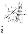
- FIG. 1 is a conceptual, constitutional, explanatory diagram showing a grism according to the embodiment of the present invention wherein a grism 10 is composed of a prism 12 the vertex angle of which can be varied and aVPH grating 16 being a diffraction grating.
- the prism 12 is composed of two plate-like outer members 12a, 12b and an inner member 12d.
- the two outer members 12a and 12b are openable in directions wherein they define an angle so as to become larger or smaller with each other at fulcrum being an end 12a-t of the outer member 12a and an end 12b-t of the outer member 12b.
- the inner member 12d has been sealed in an internal space defined by a rubber-like sealing member 12c provided so as to connect the other end 12a-b of the outer member 12a with the other end 12b-b of the outer member 12b.
- the outer members 12a and 12b as well as the inner member 12d are made from a transparent material.
- the outer members 12a and 12b are made from glass, while silicon oil being a liquid transparent in a region of wavelength applied is used for the inner member 12d.
- the sealing member 12c is made from, for example, a synthetic rubber.
- An angle defined by the outer member 12a and the outer member 12b of the prism 12 is made to be the vertex angle ⁇ of the prism 12.
- the vertex angle ⁇ of the prism 12 is made to be variable by means of a driving means (not shown).
- a material for preparing the VPH grating 16 maybe, for example, gelatin bichromate, a photosensitive resin or the like.
- the VPH grating 16 is disposed substantially orthogonally with respect to a side including the vertex angle ⁇ of the prism 12 (corresponding to a plane of the prism 12 showing a region of a substantially triangular contour in FIG. 1).
- an angle defined by the VPH grating 16 stuck fast to the outer member 12a and a plane perpendicular to incident light is made to be a slope angle ⁇ of the grism 10.
- the slope angle ⁇ of the grism 10 is made to be variable by means of a driving means (not shown).
- the VPH grating 16 may be a member sandwiched in between two holding substrates 17-1 and 17-2.
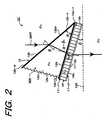
- the holding substrate 17-1 for holding the VPH grating 16 is positioned in between the VPH grating and the prism 12 as in a grism 10' shown in FIG. 2.
- the holding substrate 17-1 and the holding substrate 17-2 are made respectively from a material being transparent and homogeneous in a region of wavelength applied, for example, glass or a plastic (resin). Furthermore, it is preferred that refractive indices of the holding substrates 17-1 and 17-2 are made to be equal to that of the VPH grating 16.
- light is input from the outside through a surface of the prism 12, in other words, light is input from an incidence plane 12bb of the outer member 12b in the prism 12, the light transmitted through the prism 12 is input to the VPH grating 16, and the light transmitted through the VPH grating 16 is output from a side of an end 16a of the VPH grating 16 to the outside in case of applying the grism 10 (see FIG. 1).
- the grism 10' having the holding substrates 17-1 and 17-2 (see FIG. 2)
- light is input from the outside through a surface of the prism 12, in other words, light is input from the incidence plane 12bb of the outer member 12b in the prism 12, the light transmitted through the prism 12 is input to the VPH grating 16, and the light transmitted through the VPH grating 16 is output from a side of an end 17-2 of the holding substrate 17-2.
- the inner member 12d is shifted, for example, in response to such movement that the end 12b-b of the outer member 12b is made to be either away from or close to the end 12a-t of the outer member 12a by means of driving force of a driving means (not shown) at fulcrum of the end 12b-t of the outer member 12b and the end 12a-t of the outer member 12a in the prism 12, whereby the vertex angle ⁇ of the prism 12 is varied.
- the VPH grating 16 is a diffraction grating which exhibits the highest efficiency in the case when it satisfies Bragg's condition.
- formulae of the incidence plane 12bb of light in the prism 12 and refraction in an interface of the prism 12 and the VPH grating 16 are given by the following formulae (2) and (3) where a refractive index of an external medium is "n 0 ", a refractive index of the inner member 12d in the prism 12 is “n 1 ", and a refractive index of the VPH grating 16 is "n 2 ".
- outgoing beam is output to the outside from either a surface of the VPH grating 16 (for example, the end 16a of the VPH grating 16 in case of the grism 10 shown in FIG. 1) or a surface of holding substrates sandwiching the VPH grating 16 between them (for example, an end 17-2a of the holding substrate 17-2 in case of the grism 10' shown in FIG. 2) in a direction of an angle ⁇ 3 defined by the outgoing beam and incident light with satisfaction of Bragg' s condition.
- a formula of refraction in either a surface of the VPH grating 16 or a surface of the holding substrates sandwiching the VPH grating 16 between them is expressed by the following formula (5).
- n 2 sin ⁇ b n 0 ⁇ sin ⁇ + ⁇ 3
- wavelength can be varied under the condition where high diffraction efficiency is kept while maintaining always Bragg's condition (see the diffraction efficiency (d) shown in FIG. 4).
- a grism is prepared by combining a surface of a prism the vertex angle of which is variable with a transmission diffraction grating (relief grating) having a stepped profile.
- a transmission diffraction grating relievef grating
- highly dispersive spectrometry can be conducted by the use of the grism 10 or 10' according to the present invention in wide wavelength with maintaining high efficiency.
- such efficient spectrometry as described above cannot be attained by the use of a grism which is prepared by combining a surface of a prism the vertex angle of which is variable with a transmission diffraction grating having a stepped profile.
- the invention is not limited to such arrangement that light is input from the incidence plane 12bb of the outer member 12b in the prism 12 the vertex angle of which is variable in the grism 10 or 10' according to the present invention.
- the grism 10 shown in FIG. 1 may be modified in such that light is input from the outside through a surface of the VPH grating 16, in other words, light is input from the end 16a of the VPH grating 16, the light input to the VPH grating 16 transmits the VPH grating 16 to be input to the prism 12, and the light thus transmitted the prism 12 is output to the outside through the incidence plane 12bb of the outer member 12b in the prism 12.
- the grism 10' shown in FIG. 2 may be arranged in such that light is input from the outside through a surface of the holding substrate 17-2, in other words, such light is input from the end 17-2a of the holding substrate 17-2, the light input to the VPH grating 16 transmits through the inside of the VPH grating 16 to be input to the prism 12, and the light thus transmitted through the inside of the prism 12 is output to the outside from the incidence plane 12bb of the outer member 12b in the prism 12.
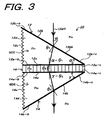
- FIG. 3 the same or equal constitution with or to that shown in FIGS. 1 and 2 are designated by the same reference characters with those applied in FIGS. 1 and 2, respectively, and the detailed description of the constitution and operations thereof are omitted.
- a grism 20 of the comparative example is compared with the grism 10 in the above-described embodiment, the former differs from the latter in that a prism 14 is further applied to the latter constitution in addition to a prism 12.
- the grism 20 is constituted so as to sandwich a VPH grating 16 being a diffraction grating in between the prism 12 the vertex angle of which is variable and the prism 14 the vertex angle of which is variable.
- the prism 14 has a common constitution with that of the prism 12 and which is composed of two plate-like outer members 14a, 14b and an inner member 14d.
- the two outer members 14a and 14b are openable in directions wherein they define an angle so as to become larger or smaller with each other at fulcrum being an end 14a-t of the outer member 14a and an end 14b-t of the outer member 14b.
- the inner member 14d has been sealed in an internal space defined by a rubber-like sealing member 14c provided so as to connect the other end 14a-b of the outer member 14a with the other end 14b-b of the outer member 14b.
- the outer members 14a and 14b as well as the innermember 14d are made from a transparent material.
- the outer members 14a and 14b are made from glass, while silicon oil being a liquid transparent in a region of wavelength applied is used for the inner member 14d.
- the sealing member 14c is made from, for example, a synthetic rubber.
- the prism 12 is made from a material common with that of the prism 14, so that a refractive index of the prism 12 is equal to that of the prism 14.
- An angle defined by the outer member 12a and the outer member 12b of the prism 12 is considered to be a vertex angle ⁇ of the prism 12.
- an angle defined by the outer member 14a and the outer member 14b of the prism 14 is considered to be a vertex angle ⁇ of the prism 14.
- the vertex angle ⁇ of the prism 12 and the vertex angle ⁇ of the prism 14 are made to be variable by means of driving means (not shown), respectively.
- the VPH grating 16 is sandwiched in such that the outer member 12a of the prism 12 is opposed to the outer member 14a of the prism 14 as well as the vertex angle ⁇ of the prism 12 is opposed to the vertex angle ⁇ of the prism 14.
- the VPH grating 16 is disposed substantially perpendicular to a side of the prism 12 involving the vertex angle ⁇ (corresponding to a plane of the prism 12 showing a substantially triangular shape in FIG. 3) and a side of the prism 14 involving the vertex angle ⁇ of the prism 14 (corresponding to a plane of the prism 14 showing a substantially triangular shape in FIG. 3).
- the grism 20 light is input from the outside through a surface of the prism 12, in other words, light is input from the incidence plane 12bb of the outer member 12b in the prism 12, the light input to the inside of the prism 12 transmits through the same, the light thus transmitted is input to the VPH grating 16, and the light transmitted inside the VPH grating 16 is input to the inside of the prism 14.
- the light input inside the prism 14 transmits through the prism 14, and is output to the outside through a surface of the prism 14, in other words, the light is output to the outside from the side of the outer member 14b of the prism 14.
- the inner member 14d varies in response to the movement of the outer member 14b, whereby the vertex angle ⁇ of the prism 12 can be varied.
- the VPH grating 16 is a diffraction grating which exhibits the highest efficiency in the case when it satisfies Bragg's condition.
- formulae of the incidence plane 12bb of light in the prism 12 and refraction in an interface of the prism 12 and the VPH grating 16 are given by the following formulae (10) and (11) where a refractive index of an external medium is "n 0 ", and a refractive index of the prism 12 is "n 1 ".
- a material of the prism 12 is changed to be twice larger than that of an external medium in response to variations of the medium applied outside the prism 12, for example, variations in media of air, water, the other types of liquid and the like.
- the grism 20 of the comparative example highly dispersive spectrometry can be conducted in wide wavelength with the use of a single grism, but not a plurality of grisms while maintaining high efficiency.
- a position to which light is input from the incidence plane 12bb of the outer member 12b in the prism 12 coincides with that through which light is output to the outside from the side 14b of the outer member 14b in the prism 14, so that highly dispersive spectrometry can be effected in wide wavelength without displacing optical axis.
- the grism 20 it is not limited to such case that light is input from the incidence plane 12bb of the outer member 12b in the prism 12, but it may be a case where light is input from the outside through a surface of the prism 14, in other words, light is input from the side of the outer member 14b, the light input inside the prism 14 transmits through the prism 14 to be input to the VPH grating 16, and the light transmitted through the VPH grating 16 is input into the prism 12.
- the light input inside the prism 12 may be output from a surface of the prism 12 after passing through the inside thereof, in other words, it may be arranged that the light is output from the incidence plane 12bb of the outer member 12b in the prism 12.
- highly dispersive spectrometry can be implemented in wide wavelength while keeping high efficiency.
- a transmission grating (see FIG. 5(b)) being a different one from such a conventional reflection grating as described above is known.
- a collimator, a camera (condenser) lens and the like may be disposed in the vicinities of the transmission grating (being a dispersive element), so that aperture ratio (F-value) becomes small.
- the resulting optical system is not folded, but the optical system can be arranged in a straight line.
- a collimator, a camera (condenser) lens and the like can be disposed in the vicinities of the grism being a dispersive element, besides in straight line.
- any of the grisms 10 and 10' according to the embodiment of the present invention is a grism of direct sight transmission grating.
- collimators, camera (condenser) lenses and the like may be disposed in the vicinities of any of the grisms 10, 10', and 20, besides they may be aligned in straight line, whereby an optical system can be constituted in a small space, so that more downsizing of the whole apparatus can be realized.
- FIG. 6 is a schematic constitutional explanatory diagram showing an example of an optical system constituted by applying the grism 10 according to the embodiment of the present invention to a variety of apparatuses.
- a refractive index n 0 of an external medium is 1.0.
- the vertex angle ⁇ of the prism 12 and the slope angle ⁇ of the VPH grating 16 are varied (see the grism 10 shown by a broken line in FIG. 6) so as to maintain Bragg's condition, wavelength can be varied while keeping high diffraction efficiency, whereby diffraction ray can be output in a rectilinearly propagating direction.
- a lens 101 through which light to be input to the incidence plane 12bb passes is disposed, while, in the vicinities of the end 16a of the VPH grating 16, a lens 102 through which light output from the end 16a to the outside passes is disposed.
- FIG. 7 is a schematic constitutional explanatory diagram showing an example of an optical system constituted by applying the grism 20 according to the comparative example to a variety of apparatuses.
- this optical system when the vertex angle ⁇ of the prism 12 being a prism on an incident side is varied in the case where a refractive index n 1 of the prism 12 is 2, Bragg's condition can be satisfied substantially, so that wavelength can be varied with holding high diffraction efficiency.
- a lens 104 through which light to be input to the incidence plane 12bb passes is disposed, while, in the vicinities of the outer member 14b of the prism 14, a lens 106 through which light output from the outer member 14b to the outside passes is placed.
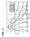
- FIG. 4 is a graphical representation indicating diffraction efficiencies of a variety of diffraction gratings.
- diffraction efficiency of a transmission grating having a stepped profile does not reach 100% in principle in even blaze wavelength as in the diffraction efficiency (f) indicated in FIG. 4.
- diffraction efficiency cannot be changed remarkably.
- the present invention Since the present invention has been constituted as described above, it can provide a grism having such an excellent advantage that highly dispersive spectrometry can be conducted in wide wavelength by the use of a single grism, but not a plurality of grisms.
Landscapes
- Physics & Mathematics (AREA)
- Spectroscopy & Molecular Physics (AREA)
- General Physics & Mathematics (AREA)
- Optics & Photonics (AREA)
- Optical Elements Other Than Lenses (AREA)
- Diffracting Gratings Or Hologram Optical Elements (AREA)
Description
- The present invention relates to a direct sight grism, and more particularly to a grism used suitably for a variety of apparatuses in observation for astronomy, earth and planetary science, meteorology, environmental hygienics and the like; various spectroscopic analyzer for physics and chemistry, pathology or the like and applied to mineral substances, living organisms or the like; manufacturing installations and quality control systems for foodstuffs, medicines, chemical products or the like; and all-optical routing apparatus relating to bare bones of Wavelength Division Multiplexing (WDM) in optical communication.
- It is to be noted herein that "grism" is a transmission type dispersive element prepared by combining a prism or prisms with a transmission grating so as to allow a light beam having an arbitrary order and an arbitrary wavelength to go straight or in an arbitrary direction.
- In recent years, a number of apparatuses for observation having both functions of imaging function and spectroscopic function have been developed with progress of two-dimensional detectors in fields of astronomy, earth and planetary science, meteorology, and environmental hygienics. In such an apparatus for observation, a grism is frequently used for a dispersive element.
- A prism-grating-prism (PGP) optical device is discussed in a publication given in VTT Publications,
Finland XP002253493435 by Aikio, Mauri - The PGP serves the purpose of a low-cost spectrometer and includes a volume phase holographic (VPH) grating sandwiched between two stationary glass prisms. The device is designed for a particular wavelength range and beforehand, the mechanical and optical parameters for each component are considered including an optimized value for the vertex angle of the prisms.
-
US-A-5166831 describe a light beam deflecting apparatus including a fluid sandwiched between first and second plates. A connector is attached to the first and second plates for connecting the plates to one another and for permitting the plates to be displaced relative to one another. The position of the first plate relative to the second plate may be varied so as to change the direction of the beam. - Since a vertex angle of a prism constituting a grism is fixed in a conventional grism, rectilinear propagating wavelength and most effective wavelength have been fixed also.
- For this reason, there has been such a problem that a plurality of grisms having different rectilinear propagating wavelengths must be prepared in the case where highly dispersive spectroscopy is conducted in wide wavelength.
- The present invention has been made in view of the above-described problems involved in the prior art, and an object of the invention is to provide a grism by which highly dispersive spectroscopy can be effected in a wide wavelength with use of a single member thereof without requiring a plurality of grisms.
- In order to achieve the above-described object, a grism according to
claim 1 invention is constituted by combining a prism a vertex angle of which can be varied with a volume phase holographic (VPH) grating. - More specifically, the grism according to the present invention comprises a prism the vertex angle of which can be varied; and a VPH grating being a diffraction grating and disposed substantially orthogonal with respect to a side including the vertex angle of the prism; the VPH grating being rotated around an axis being substantially orthogonal to the side of the prism, whereby a slope angle defined by the VPH grating and a predetermined plane is varied.
- In addition, a grism according to the present invention is arranged in such that the prism is prepared from two outer members made of a transparent material and an inner member being a liquid transparent in a region of wavelength applied and sealed in between the two outer members.
- Further, a grism according to the present invention is arranged in such that a direction of light to be output to the outside is maintained in a predetermined direction by varying the vertex angle of the prism and the slope angle to predetermined angles, respectively, whereby a state wherein the VPH grating satisfies Bragg's condition is kept as it is.
- The present invention will become more fully understood from the detailed description given hereinafter and the accompanying drawings which are given by way of illustration only, and thus are not limitative of the present invention, and wherein:
- FIG. 1 is a conceptual, constitutional, explanatory diagram showing an embodiment of the grism according to the present invention;
- FIG. 2 is a conceptual, constitutional, explanatory diagram showing another example of the embodiment of the grism according to the present invention;
- FIG. 3 is a conceptual, constitutional, explanatory diagram showing a comparative example of the direct sight grism;
- FIG. 4 is a graphical representation indicating diffraction efficiencies of cases (a) and (e) wherein an incident angle is fixed so as to be Bragg angle with respect to the maximum efficient wavelength of a VPH grating having either a refractive index modulation amount Δn 0.02 and 0.04, respectively, cases (b) and (c) wherein an incident angle is adjusted so as to satisfy conditions of Bragg diffraction in every wavelengths with respect to a VPH grating having a refractive index modulation amount An 0.02, respectively, an envelope curve of a case (d) wherein an incident angle is maintained always at Bragg angle, and a relief grating (f), respectively;
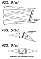
- FIG. 5(a) is an explanatory diagram showing an example of a conventional reflection grating;
- FIG. 5(b) is an explanatory diagram showing an example of transmission grating;
- FIG. 5(c) is an explanatory diagram showing an example of grism (direct sight transmission grating);
- FIG. 6 is a schematic, constitutional, explanatory diagram showing an example of an optical system which is constituted by applying the grism of the embodiment shown in FIG. 1 according to the present invention to a variety of apparatuses or constituted in accordance with the like manner; and
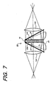
- FIG. 7 is a schematic, constitutional, explanatory diagram showing a comparative example of an optical system which is constituted by applying the grism shown in FIG. 3 to a variety of apparatuses or constituted in accordance with the like manner.
- An example of preferred embodiment of a grism according to the present invention will be described in detail hereinafter by referring to the accompanying drawings.
- FIG. 1 is a conceptual, constitutional, explanatory diagram showing a grism according to the embodiment of the present invention wherein a
grism 10 is composed of aprism 12 the vertex angle of which can be varied and aVPH grating 16 being a diffraction grating. - The
prism 12 is composed of two plate-likeouter members inner member 12d. In this case, the twoouter members end 12a-t of theouter member 12a and anend 12b-t of theouter member 12b. Theinner member 12d has been sealed in an internal space defined by a rubber-like sealingmember 12c provided so as to connect theother end 12a-b of theouter member 12a with theother end 12b-b of theouter member 12b. - In this case, the
outer members inner member 12d are made from a transparent material. For example, theouter members inner member 12d. Furthermore, the sealingmember 12c is made from, for example, a synthetic rubber. - An angle defined by the
outer member 12a and theouter member 12b of theprism 12 is made to be the vertex angle α of theprism 12. The vertex angle α of theprism 12 is made to be variable by means of a driving means (not shown). - On the other hand, a material for preparing the VPH grating 16maybe, for example, gelatin bichromate, a photosensitive resin or the like. The
VPH grating 16 is disposed substantially orthogonally with respect to a side including the vertex angle α of the prism 12 (corresponding to a plane of theprism 12 showing a region of a substantially triangular contour in FIG. 1). - Moreover, an angle defined by the VPH grating 16 stuck fast to the
outer member 12a and a plane perpendicular to incident light is made to be a slope angle β of thegrism 10. The slope angle β of thegrism 10 is made to be variable by means of a driving means (not shown). - The VPH grating 16 may be a member sandwiched in between two holding substrates 17-1 and 17-2. In this case, the holding substrate 17-1 for holding the
VPH grating 16 is positioned in between the VPH grating and theprism 12 as in a grism 10' shown in FIG. 2. - The holding substrate 17-1 and the holding substrate 17-2 are made respectively from a material being transparent and homogeneous in a region of wavelength applied, for example, glass or a plastic (resin). Furthermore, it is preferred that refractive indices of the holding substrates 17-1 and 17-2 are made to be equal to that of the VPH grating 16.
- In the above described constitution, light is input from the outside through a surface of the
prism 12, in other words, light is input from an incidence plane 12bb of theouter member 12b in theprism 12, the light transmitted through theprism 12 is input to the VPH grating 16, and the light transmitted through theVPH grating 16 is output from a side of anend 16a of the VPH grating 16 to the outside in case of applying the grism 10 (see FIG. 1). - Moreover, in case of the grism 10' having the holding substrates 17-1 and 17-2 (see FIG. 2), light is input from the outside through a surface of the
prism 12, in other words, light is input from the incidence plane 12bb of theouter member 12b in theprism 12, the light transmitted through theprism 12 is input to theVPH grating 16, and the light transmitted through theVPH grating 16 is output from a side of an end 17-2 of the holding substrate 17-2. - In the arrangement, it is possible that the
inner member 12d is shifted, for example, in response to such movement that theend 12b-b of theouter member 12b is made to be either away from or close to theend 12a-t of theouter member 12a by means of driving force of a driving means (not shown) at fulcrum of theend 12b-t of theouter member 12b and theend 12a-t of theouter member 12a in theprism 12, whereby the vertex angle α of theprism 12 is varied. - Likewise, it is possible that when either the
whole grism 10 or 10' is rotated at fulcrum of theend 16t of the VPH grating 16 on the side of the vertex angle α of theprism 12 around the axis substantially orthogonal to a side of theprism 12, the slope angle β defined by theVPH grating 16 and aplane 100 perpendicular to incident light is varied. - In case of a relief grating the surface of which has a saw-shaped grating profile, even if a vertex angle or incidence angle of a prism substrate is varied, its diffraction efficiency cannot be remarkably changed as shown in FIG. 4.
- On the other hand, the VPH grating 16 is a diffraction grating which exhibits the highest efficiency in the case when it satisfies Bragg's condition.
- When it is assumed that a refractive index of the
VPH grating 16 is "n2", lattice spacing is "d", an order of diffraction is "m", and a wavelength is "λ" in the case where gratings of the VPH grating 16 are substantially perpendicular to surfaces and sides of the VPH grating 16, the following formula (1) of an equation of Bragg diffraction is obtained.
where θb is Bragg angle. - In FIG. 1, formulae of the incidence plane 12bb of light in the
prism 12 and refraction in an interface of theprism 12 and theVPH grating 16 are given by the following formulae (2) and (3) where a refractive index of an external medium is "n0", a refractive index of theinner member 12d in theprism 12 is "n1", and a refractive index of theVPH grating 16 is "n2".

- In this case, when θ2 satisfies Bragg' s condition, it result in θ2 = θb. Accordingly, the formula (3) is expressed by the following formula (4).

- On one hand, outgoing beam is output to the outside from either a surface of the VPH grating 16 (for example, the
end 16a of the VPH grating 16 in case of thegrism 10 shown in FIG. 1) or a surface of holding substrates sandwiching the VPH grating 16 between them (for example, an end 17-2a of the holding substrate 17-2 in case of the grism 10' shown in FIG. 2) in a direction of an angle θ3 defined by the outgoing beam and incident light with satisfaction of Bragg' s condition. In this case, a formula of refraction in either a surface of the VPH grating 16 or a surface of the holding substrates sandwiching the VPH grating 16 between them is expressed by the following formula (5).
- In this case, even if Bragg's condition is not strictly satisfied, diffraction efficiency of the VPH grating 16 is high in the vicinity of Bragg angle (see the diffraction efficiency (e) shown in FIG. 4),


- In the case when outgoing beam is output to the outside in parallel to incident light, θ3 = 0, so that the formula (5) turns to a formula (7).

- On one hand, the formula (6) turns to the following formula (8).

- In other words, when the vertex angle α of the
prism 12 and the slope angle β defined by the VPH grating 16 and theplane 100 perpendicular to incident light are varied at a ratio determined by the above-described formula (6) or (8) , wavelength can be varied under the condition where high diffraction efficiency is kept while maintaining always Bragg's condition (see the diffraction efficiency (d) shown in FIG. 4). - For instance, wavelength can be varied while keeping high diffraction efficiency, when a ratio is arranged to be α = 4β in the case where a refractive index "n0" of an external medium is 1.0, outgoing beam is output to the outside in parallel to incident light, and a refractive index "n1" of the
inner member 12d is 1.5, while a ratio is arranged to be α = 2β in the case where "n1" is 2.0. - As a result, high dispersive spectrometry of wide wavelength can be implemented with single use of grism in accordance with the
grism 10 or 10' of the present invention without requiring a plurality of grisms while maintaining high efficiency. - On one hand, it is also possible that a grism is prepared by combining a surface of a prism the vertex angle of which is variable with a transmission diffraction grating (relief grating) having a stepped profile. However, in such grism as described above, when the vertex angle of a prism is varied, a direction of outgoing beam and a wavelength thereof can be arbitrarily changed, but the most efficient wavelength cannot be varied (see the diffraction efficiency (f) shown in FIG. 4).
- More specifically, highly dispersive spectrometry can be conducted by the use of the
grism 10 or 10' according to the present invention in wide wavelength with maintaining high efficiency. On the contrary, such efficient spectrometry as described above cannot be attained by the use of a grism which is prepared by combining a surface of a prism the vertex angle of which is variable with a transmission diffraction grating having a stepped profile. - Furthermore, it is to be noted that the invention is not limited to such arrangement that light is input from the incidence plane 12bb of the
outer member 12b in theprism 12 the vertex angle of which is variable in thegrism 10 or 10' according to the present invention. - For instance, the
grism 10 shown in FIG. 1 may be modified in such that light is input from the outside through a surface of the VPH grating 16, in other words, light is input from theend 16a of the VPH grating 16, the light input to the VPH grating 16 transmits the VPH grating 16 to be input to theprism 12, and the light thus transmitted theprism 12 is output to the outside through the incidence plane 12bb of theouter member 12b in theprism 12. - The grism 10' shown in FIG. 2 may be arranged in such that light is input from the outside through a surface of the holding substrate 17-2, in other words, such light is input from the end 17-2a of the holding substrate 17-2, the light input to the VPH grating 16 transmits through the inside of the VPH grating 16 to be input to the
prism 12, and the light thus transmitted through the inside of theprism 12 is output to the outside from the incidence plane 12bb of theouter member 12b in theprism 12. - In even such situations as mentioned above, highly dispersive spectrometry can be implemented in wide wavelength while keeping high efficiency in the
grism 10 or 10' according to the present invention. - In the following, a comparative example of a direct sight grism will be described by referring to FIG. 3.
- In FIG. 3, the same or equal constitution with or to that shown in FIGS. 1 and 2 are designated by the same reference characters with those applied in FIGS. 1 and 2, respectively, and the detailed description of the constitution and operations thereof are omitted.
- When a
grism 20 of the comparative example is compared with thegrism 10 in the above-described embodiment, the former differs from the latter in that aprism 14 is further applied to the latter constitution in addition to aprism 12. - More specifically, the
grism 20 is constituted so as to sandwich aVPH grating 16 being a diffraction grating in between theprism 12 the vertex angle of which is variable and theprism 14 the vertex angle of which is variable. - The
prism 14 has a common constitution with that of theprism 12 and which is composed of two plate-likeouter members inner member 14d. In this case, the twoouter members end 14a-t of theouter member 14a and anend 14b-t of theouter member 14b. Theinner member 14d has been sealed in an internal space defined by a rubber-like sealing member 14c provided so as to connect theother end 14a-b of theouter member 14a with theother end 14b-b of theouter member 14b. - In this case, the
outer members innermember 14d are made from a transparent material. For example, theouter members inner member 14d. Furthermore, the sealingmember 14c is made from, for example, a synthetic rubber. - In the comparative example, the
prism 12 is made from a material common with that of theprism 14, so that a refractive index of theprism 12 is equal to that of theprism 14. - An angle defined by the
outer member 12a and theouter member 12b of theprism 12 is considered to be a vertex angle α of theprism 12. On one hand, an angle defined by theouter member 14a and theouter member 14b of theprism 14 is considered to be a vertex angle γ of theprism 14. The vertex angle α of theprism 12 and the vertex angle γ of theprism 14 are made to be variable by means of driving means (not shown), respectively. - The
VPH grating 16 is sandwiched in such that theouter member 12a of theprism 12 is opposed to theouter member 14a of theprism 14 as well as the vertex angle α of theprism 12 is opposed to the vertex angle γ of theprism 14. In this case, the VPH grating 16 is disposed substantially perpendicular to a side of theprism 12 involving the vertex angle α (corresponding to a plane of theprism 12 showing a substantially triangular shape in FIG. 3) and a side of theprism 14 involving the vertex angle γ of the prism 14 (corresponding to a plane of theprism 14 showing a substantially triangular shape in FIG. 3). - In the above-described constitution of the
grism 20, light is input from the outside through a surface of theprism 12, in other words, light is input from the incidence plane 12bb of theouter member 12b in theprism 12, the light input to the inside of theprism 12 transmits through the same, the light thus transmitted is input to the VPH grating 16, and the light transmitted inside the VPH grating 16 is input to the inside of theprism 14. The light input inside theprism 14 transmits through theprism 14, and is output to the outside through a surface of theprism 14, in other words, the light is output to the outside from the side of theouter member 14b of theprism 14. - In this situation, it is possible that when the
outer member 12b of theprism 12 is transferred by means of a driving means (not shown) in a direction wherein theouter member 12b comes to be away from or close to theouter member 12a, theinner member 12d varies in response to the movement of theouter member 12b, whereby the vertex angle α of theprism 12 can be varied. - Likewise, it is possible that when the
outer member 14b of theprism 14 is transferred by means of a driving means (not shown) in a direction wherein theouter member 14b comes to be away from or close to theouter member 14a, theinner member 14d varies in response to the movement of theouter member 14b, whereby the vertex angle γ of theprism 12 can be varied. - In case of a relief grating the surface of which has a saw-shaped grating profile, even if a vertex angle or incidence angle of a prism substrate is varied, its diffraction efficiency cannot be remarkably changed as shown in FIG. 4.
- On the other hand, the VPH grating 16 is a diffraction grating which exhibits the highest efficiency in the case when it satisfies Bragg's condition.
- When it is assumed that a refractive index of the VPH grating 16 is "n2", lattice spacing is "d", an order of diffraction is "m", and a wavelength is "λ" in the case where gratings of the VPH grating 16 are substantially perpendicular to surfaces and sides of the VPH grating 16, the following formula (9) of an equation of Bragg diffraction is obtained.

where θb is Bragg angle. - In FIG. 3, formulae of the incidence plane 12bb of light in the
prism 12 and refraction in an interface of theprism 12 and the VPH grating 16 are given by the following formulae (10) and (11) where a refractive index of an external medium is "n0", and a refractive index of theprism 12 is "n1".

- In this case, when it is assumed that θ2 = θb, and the formula (11) is replaced by the formula (9), the formula (12) is obtained.

wherein theprism 12 the vertex angle of which can be varied exhibits a refractive index of twice larger than the refractive index "n0" of an external medium of theprism 12. Namely, sin α = 2 sin θ from the Formula (10) in case of n1 = 2n0, so that the formula (12) is expressed as follows, when it may be assumed that α = 2 θ1.
- From the formulae (13) and (10), the following formula (14) is introduced.

- Namely, when the vertex angle α is varied in the above-described formula (14) , its wavelength can be varied under the condition wherein high efficiency is maintained while keeping always Bragg's condition.
- Moreover, when a refractive index of the
prism 14 the vertex angle of which can be varied is considered to be "n3",
- Furthermore, when it is assumed that outgoing beam moves through in a direction of an angle θ4 defined by the outgoing beam and incident light, the following formula is expressed.

- When n3 = 2n0, and θ4 = 0, the Formula (16) becomes


- As a result, a formula (19) is introduced from the formulae (18) and (17)

- From the formulae (19) and (14), it becomes

- For instance, when an external medium of the
grism 20 is air, a refractive index n1 of theprism 12 is made to be n1 = 2 with respect to refractive index of air "n0 = 1", a wavelength can be varied in the condition wherein high efficiency is maintained, because the VPH grating 16 satisfies Bragg's condition. - Accordingly, it is suitable that a material of the
prism 12 is changed to be twice larger than that of an external medium in response to variations of the medium applied outside theprism 12, for example, variations in media of air, water, the other types of liquid and the like. - Thus, according to the
grism 20 of the comparative example, highly dispersive spectrometry can be conducted in wide wavelength with the use of a single grism, but not a plurality of grisms while maintaining high efficiency. - Furthermore, in the
grism 20 according to the comparative example, a position to which light is input from the incidence plane 12bb of theouter member 12b in theprism 12 coincides with that through which light is output to the outside from theside 14b of theouter member 14b in theprism 14, so that highly dispersive spectrometry can be effected in wide wavelength without displacing optical axis. - Moreover, when the vertex angle γ is arbitrarily selected, it is also possible to move an arbitrary wavelength in a desired direction.
- In the
grism 20, it is not limited to such case that light is input from the incidence plane 12bb of theouter member 12b in theprism 12, but it may be a case where light is input from the outside through a surface of theprism 14, in other words, light is input from the side of theouter member 14b, the light input inside theprism 14 transmits through theprism 14 to be input to the VPH grating 16, and the light transmitted through the VPH grating 16 is input into theprism 12. In this case, the light input inside theprism 12 may be output from a surface of theprism 12 after passing through the inside thereof, in other words, it may be arranged that the light is output from the incidence plane 12bb of theouter member 12b in theprism 12. According to thegrism 20 of the comparative example, in such a case also, highly dispersive spectrometry can be implemented in wide wavelength while keeping high efficiency. - In the following, applications of the grisms of the embodiment according to the present invention and the comparative example to a variety of apparatuses will be described in more detail.
- First, a conventional reflection grating (see FIG. 5(a)) has a large aperture ratio (F-value = focal length f/diameter D), so that its optical system becomes dark. For this reason, a conventional reflection grating has been a large diameter for requiring quantity of light.
- As a result, when a conventional reflection grating is applied to a variety of apparatuses, there is such a problem that its optical system becomes a large-scale.
- A transmission grating (see FIG. 5(b)) being a different one from such a conventional reflection grating as described above is known. In such transmission grating, a collimator, a camera (condenser) lens and the like may be disposed in the vicinities of the transmission grating (being a dispersive element), so that aperture ratio (F-value) becomes small.
- As a result, when a transmission grating is applied to a variety of apparatuses, a compact and bright optical system can be realized.
- However, even in a transmission grating by which problems involved in a conventional reflection grating have been eliminated by the above-described manner, when a transmission grating is constituted in the form of plane diffraction grating as shown in FIG. 5(b), its optical system is folded.
- In this respect, when a grism being a direct sight transmission grating (see FIG. 5(c)) is used in transmission grating, the resulting optical system is not folded, but the optical system can be arranged in a straight line.
- Thus, when a grismbeing a direct sight transmission grating is applied to a variety of apparatuses, a collimator, a camera (condenser) lens and the like can be disposed in the vicinities of the grism being a dispersive element, besides in straight line.
- As a result, more downsizing of the resul ting whole apparatus becomes possible in comparison with a transmission grating constituted in the form of a plane diffraction grating as shown in FIG. 5(b).
- More specifically, any of the
grisms 10 and 10' according to the embodiment of the present invention (see FIGS. 1 and 2) as well as thegrism 20 according to the comparative example (see FIG. 3) is a grism of direct sight transmission grating. Accordingly, when thegrisms grisms - FIG. 6 is a schematic constitutional explanatory diagram showing an example of an optical system constituted by applying the
grism 10 according to the embodiment of the present invention to a variety of apparatuses. In this optical system, when a refractive index n1 of theinner member 12d of theprism 12 in thegrism 10 is in a condition of n1 ≠ 2, for example, n1 = 1.5, a refractive index n0 of an external medium is 1.0. In this situation, when the vertex angle α of theprism 12 and the slope angle β of the VPH grating 16 are varied (see thegrism 10 shown by a broken line in FIG. 6) so as to maintain Bragg's condition, wavelength can be varied while keeping high diffraction efficiency, whereby diffraction ray can be output in a rectilinearly propagating direction. - However, it is to be noted that an optical axis of incident light and that of outgoing beam shift in parallel to each other in case of using the grism 10 (see FIGS. 1 and 2).
- In the vicinities of the incidence plane 12bb of the
outer member 12b of theprism 12, a lens 101 through which light to be input to the incidence plane 12bb passes is disposed, while, in the vicinities of theend 16a of the VPH grating 16, alens 102 through which light output from theend 16a to the outside passes is disposed. - Thus, other optical parts are placed in a straight line in the vicinities of the
grism 10 disposed in between the lens 101 and thelens 102 the optical axes of which are in a straight line (see the dashed line shown in FIG. 6) , whereby the resulting optical system can be constituted in a small space without any fold. - FIG. 7 is a schematic constitutional explanatory diagram showing an example of an optical system constituted by applying the
grism 20 according to the comparative example to a variety of apparatuses. In this optical system, when the vertex angle α of theprism 12 being a prism on an incident side is varied in the case where a refractive index n1 of theprism 12 is 2, Bragg's condition can be satisfied substantially, so that wavelength can be varied with holding high diffraction efficiency. - In this case, when the vertex angle γ of the
prism 14 on an outgoing side is made to be equal to the vertex angle α of theprism 12 on the incident side (see thegrism 20 indicated by a broken line in FIG. 7), diffraction ray propagates rectilinearly. - On the other hand, when the vertex angle γ of the
prism 14 is made to be different from the vertex angle α of theprism 12, diffraction ray can be output in an arbitrary direction. - In the vicinities of the incidence plane 12bb of the
outer member 12b of theprism 12, alens 104 through which light to be input to the incidence plane 12bb passes is disposed, while, in the vicinities of theouter member 14b of theprism 14, alens 106 through which light output from theouter member 14b to the outside passes is placed. - Thus, other optical parts are placed in a straight line in the vicinities of the
grism 20 disposed in between thelens 104 and thelens 106 the optical axes of which are in a straight line (see the dashed line indicated in FIG. 7), whereby the resulting optical system can be constituted in a small space without any fold. - FIG. 4 is a graphical representation indicating diffraction efficiencies of a variety of diffraction gratings.
- More specifically, when an incident angle is fixed in a VPH grating, a range of wavelength in which high efficiency is attained as in the diffraction efficiencies (a) and (e) indicated in FIG. 4 becomes narrow.
- However, when incident angle is adjusted so as to satisfy a condition of Bragg diffraction in every wavelengths as in the diffraction efficiency (b) and the diffraction efficiency (c) indicated in FIG. 4, itbecomes possible to attain high efficiency in a wide range represented by an envelop curve of the diffraction efficiency (d).
- Contrary to such VPH grating, diffraction efficiency of a transmission grating having a stepped profile (relief grating) does not reach 100% in principle in even blaze wavelength as in the diffraction efficiency (f) indicated in FIG. 4. Thus, even if an incident angle or the like is adjusted, diffraction efficiency cannot be changed remarkably.
- Consequently, highly dispersive spectrometry is realized in wide wavelength by the use of one or more of the
grisms - In addition, more downsizing of the whole apparatus can be realized in accordance with the description shown in FIGS. 5 and 6.
- It is to be noted that the above-described embodiment may be modified as enumerated in the following paragraphs (1) to (3).
- (1) In the above-described embodiments, although gelatin bichromate, a photosensitive resin and the like have been used for preparing the VPH grating 16, the present invention is not limited thereto as a matter of course.
- (2) In the above-described embodiments, although it has been arranged to vary a vertex angle of the
prism - (3) The above-described embodiment as well as the modifications (1) and (2) described in the above paragraphs may be appropriately combined with each other.
- Since the present invention has been constituted as described above, it can provide a grism having such an excellent advantage that highly dispersive spectrometry can be conducted in wide wavelength by the use of a single grism, but not a plurality of grisms.
Claims (5)
- A direct sight grism maintaining a direction of light to be output in a predetermined direction, comprising
a single prism (12) ; and
a volume phase holographic (VPH) grating (16) combined with said prism,
characterized in that
said grism comprises means for varying the vertex angle α of said prism and a slope angle β defined by the angle between plane of the VPH grating and a plane (100) perpendicular to the predetermined direction of light. - A grism as claimed in claim 1, wherein
said VPH grating (16) being a diffraction grating disposed substantially orthogonal with respect to a side of said prism (12) including the vertex angle α;
said grism is rotatable at the fulcrum of the end (16t) of said VPH grating (16) around an axis substantially orthogonal to said side of said prism including the vertex angle α, whereby the slope angle β is varied. - A grism as claimed in claim 1, further comprising
holding substrates (17-1, 17-2) for holding said VPH grating (16). - A grism as claimed in any one of claims 1 to 3 wherein said prism (12) is prepared from two outer members (12a, 12b) made of a transparent material and an inner member (12d) being a liquid-transparent in a region of wavelength applied and sealed inbetween said two outer members.
- The use of a grism as claimed in any one of claims 1 to 4 comprising the step of:varying the vertex angle α of said prism (12) and said slope angle β to predetermined angles, respectively, such that a direction of light to be output from said grism to the outside medium is maintained in a predetermined direction and a wavelength of light incident on said grism may be varied while maintaining high diffraction efficiency and Bragg's condition.
Applications Claiming Priority (2)
| Application Number | Priority Date | Filing Date | Title |
|---|---|---|---|
| JP2002170068A JP3576538B2 (en) | 2002-06-11 | 2002-06-11 | Grism |
| JP2002170068 | 2002-06-11 |
Publications (2)
| Publication Number | Publication Date |
|---|---|
| EP1372002A1 EP1372002A1 (en) | 2003-12-17 |
| EP1372002B1 true EP1372002B1 (en) | 2007-11-07 |
Family
ID=29561748
Family Applications (1)
| Application Number | Title | Priority Date | Filing Date |
|---|---|---|---|
| EP03013138A Expired - Lifetime EP1372002B1 (en) | 2002-06-11 | 2003-06-11 | Direct sight grism |
Country Status (4)
| Country | Link |
|---|---|
| US (1) | US6927914B2 (en) |
| EP (1) | EP1372002B1 (en) |
| JP (1) | JP3576538B2 (en) |
| DE (1) | DE60317263T2 (en) |
Families Citing this family (21)
| Publication number | Priority date | Publication date | Assignee | Title |
|---|---|---|---|---|
| JP4537318B2 (en) * | 2003-06-17 | 2010-09-01 | 独立行政法人理化学研究所 | Diffraction grating, manufacturing method thereof and grism |
| JP4727981B2 (en) * | 2004-12-22 | 2011-07-20 | 独立行政法人理化学研究所 | Diffraction grating device |
| DE102005002106B3 (en) * | 2005-01-14 | 2006-04-13 | Drägerwerk AG | Spectroscopic device for qualitative and quantitative analysis of gas mixtures, useful in medical and safety applications, comprising refractive-diffractive elements for wavelength-dependent imaging |
| US7307804B2 (en) * | 2005-01-14 | 2007-12-11 | Kaiser Optical Systems | Thermally stabile GRISMs |
| IL174590A (en) * | 2005-03-29 | 2015-03-31 | Yoel Arieli | Method and imaging system for analyzing optical properties of an object illuminated by a light source |
| US20070153354A1 (en) * | 2005-12-22 | 2007-07-05 | Solbeam, Inc. | Minimizing lensing in electro-optic prisms |
| DE102006015269A1 (en) * | 2006-04-01 | 2007-10-25 | Carl Zeiss Microimaging Gmbh | Spectrometric measuring system and method for compensation of stray light |
| FR2953945B1 (en) * | 2009-12-10 | 2011-12-30 | Fastlite | DEVICE FOR THE COMPENSATION OF TIME DISPERSION APPLIED TO THE GENERATION OF ULTRA BRIEF LUMINOUS PULSES. |
| JP5541972B2 (en) * | 2010-06-09 | 2014-07-09 | オリンパス株式会社 | Scanning confocal microscope |
| JP5541978B2 (en) * | 2010-06-21 | 2014-07-09 | オリンパス株式会社 | Laser scanning microscope |
| CN102662205B (en) * | 2012-05-14 | 2014-05-07 | 南京邮电大学 | Liquid prism with variable vertex angle |
| US9885606B1 (en) * | 2013-03-14 | 2018-02-06 | Wavefront Research, Inc. | Compact spectrometer with high spectral resolution |
| US10345148B1 (en) * | 2013-03-14 | 2019-07-09 | Wavefront Research, Inc. | Compact spectrometer with high spectral resolution |
| WO2017024145A1 (en) * | 2015-08-05 | 2017-02-09 | Canon U.S.A., Inc. | Forward and angle view endoscope |
| CN110346856B (en) * | 2019-07-11 | 2020-12-29 | 中国科学院福建物质结构研究所 | A kind of prism grating and wavelength division multiplexer |
| KR20210035380A (en) * | 2019-09-23 | 2021-04-01 | 삼성전자주식회사 | Optical device, camera module including the optical device, and apparatus including the camera module |
| KR102436763B1 (en) * | 2020-03-05 | 2022-08-29 | 한국전자통신연구원 | Hyperspectral sensor |
| CN112229516B (en) * | 2020-11-02 | 2025-04-25 | 苏州大学 | A spectroscopic imaging system and imaging method for snapshot imaging spectrometer |
| CN112945383A (en) * | 2021-02-05 | 2021-06-11 | 中国科学院合肥物质科学研究院 | Hyper-spectral imager optical system with high luminous flux and low spectral distortion |
| DE102022114150B4 (en) * | 2022-06-03 | 2024-09-05 | Akmira Optronics Gmbh | Optical system for digital holography |
| WO2025258691A1 (en) * | 2024-06-14 | 2025-12-18 | 国立研究開発法人理化学研究所 | Grism and aerial image display device |
Family Cites Families (9)
| Publication number | Priority date | Publication date | Assignee | Title |
|---|---|---|---|---|
| JP2674270B2 (en) * | 1990-04-12 | 1997-11-12 | キヤノン株式会社 | Optical element |
| US5166831A (en) * | 1991-10-02 | 1992-11-24 | Spectra-Physics Laserplane, Inc. | Light beam deflecting apparatus including a fluid |
| FI90289C (en) | 1992-04-08 | 1994-01-10 | Valtion Teknillinen | Optical component |
| JPH0675102A (en) * | 1992-08-28 | 1994-03-18 | Canon Inc | Optical element |
| EP0602992B1 (en) | 1992-12-18 | 1999-03-03 | Raytheon Company | Grating-prism combination |
| US5629764A (en) * | 1995-07-07 | 1997-05-13 | Advanced Precision Technology, Inc. | Prism fingerprint sensor using a holographic optical element |
| JP3012841B1 (en) * | 1998-11-04 | 2000-02-28 | 日本アイ・ビー・エム株式会社 | Single-panel color projector |
| JP4460117B2 (en) * | 2000-06-29 | 2010-05-12 | 独立行政法人理化学研究所 | Grism |
| US20020176124A1 (en) * | 2001-05-23 | 2002-11-28 | Wise Kent Lawson | Linear axially transmissive photon-diffracting device |
-
2002
- 2002-06-11 JP JP2002170068A patent/JP3576538B2/en not_active Expired - Fee Related
-
2003
- 2003-06-10 US US10/457,408 patent/US6927914B2/en not_active Expired - Fee Related
- 2003-06-11 EP EP03013138A patent/EP1372002B1/en not_active Expired - Lifetime
- 2003-06-11 DE DE60317263T patent/DE60317263T2/en not_active Expired - Fee Related
Non-Patent Citations (1)
| Title |
|---|
| None * |
Also Published As
| Publication number | Publication date |
|---|---|
| DE60317263D1 (en) | 2007-12-20 |
| US6927914B2 (en) | 2005-08-09 |
| JP3576538B2 (en) | 2004-10-13 |
| US20040070853A1 (en) | 2004-04-15 |
| JP2004013080A (en) | 2004-01-15 |
| EP1372002A1 (en) | 2003-12-17 |
| DE60317263T2 (en) | 2008-08-28 |
Similar Documents
| Publication | Publication Date | Title |
|---|---|---|
| US6927914B2 (en) | Grism | |
| US12379547B2 (en) | Waveguide grating device | |
| US6750995B2 (en) | Enhanced volume phase grating with high dispersion, high diffraction efficiency and low polarization sensitivity | |
| AU2010306070B2 (en) | Integrated photonic spectrograph | |
| JP4460117B2 (en) | Grism | |
| EP3271761B1 (en) | Unidirectional grating-based backlighting employing an angularly selective reflective layer | |
| US20040032584A1 (en) | Optical channel monitoring device | |
| US20090310963A1 (en) | Dynamic optical devices | |
| EP3698214A2 (en) | Systems and methods for multiplying the image resolution of a pixelated display | |
| US10216033B1 (en) | Color filter substrate, method for fabricating the same, and liquid crystal display panel | |
| EP1184708A2 (en) | Optical device and spectroscopic and polarization separating apparatus using the same | |
| US20060274391A1 (en) | High dispersion diffraction grating including multiple holographic optical elements | |
| US20180011334A1 (en) | Optical Arrangement for Spectral Decomposition of Light | |
| JP4727981B2 (en) | Diffraction grating device | |
| US20080239441A1 (en) | Mirror device and optical apparatus | |
| CN101023388A (en) | Method and apparatus for a Bragg grating tunable filter | |
| JP4537318B2 (en) | Diffraction grating, manufacturing method thereof and grism | |
| US5555108A (en) | Holographic exposure prism | |
| US9274348B2 (en) | Dispersive device having beam expanding optical system and dispersive element and wavelength selective switch having dispersive device | |
| Ura et al. | Vertically stacked and directionally coupled cavity-resonator-integrated grating couplers for integrated-optic beam steering | |
| US6795601B1 (en) | Achromatic optical switching/routing systems | |
| Pearson et al. | Vph transmission grating design considerations for spectrograph designers | |
| US20040201892A1 (en) | Diffraction grating element, optical module and optical communications system | |
| US20240369900A1 (en) | Wavelength selective switch | |
| Weis et al. | Fabry–Perot/Šolc filter with distributed Bragg reflectors: a narrow-band electro-optically tunable spectral filter |
Legal Events
| Date | Code | Title | Description |
|---|---|---|---|
| PUAI | Public reference made under article 153(3) epc to a published international application that has entered the european phase |
Free format text: ORIGINAL CODE: 0009012 |
|
| AK | Designated contracting states |
Kind code of ref document: A1 Designated state(s): AT BE BG CH CY CZ DE DK EE ES FI FR GB GR HU IE IT LI LU MC NL PT RO SE SI SK TR |
|
| AX | Request for extension of the european patent |
Extension state: AL LT LV MK |
|
| RIN1 | Information on inventor provided before grant (corrected) |
Inventor name: OKA, KEIKO Inventor name: KODATE, KASHIKO Inventor name: IE, MASANORI Inventor name: EBISUZAKI, TOSHIKAZUC/O RIKEN Inventor name: EBIZUKA, NOBORUC/O RIKEN |
|
| 17P | Request for examination filed |
Effective date: 20040422 |
|
| 17Q | First examination report despatched |
Effective date: 20040526 |
|
| RIN1 | Information on inventor provided before grant (corrected) |
Inventor name: EBIZUKA, NOBORUC/O RIKEN Inventor name: EBISUZAKI, TOSHIKAZUC/O RIKEN Inventor name: OKA, KEIKO Inventor name: IE, MASANORI, NATIONAL INSTIT. OF NATURAL SCIENCES Inventor name: KODATE, KASHIKO |
|
| AKX | Designation fees paid |
Designated state(s): DE FR GB |
|
| RTI1 | Title (correction) |
Free format text: DIRECT SIGHT GRISM |
|
| GRAP | Despatch of communication of intention to grant a patent |
Free format text: ORIGINAL CODE: EPIDOSNIGR1 |
|
| GRAS | Grant fee paid |
Free format text: ORIGINAL CODE: EPIDOSNIGR3 |
|
| GRAA | (expected) grant |
Free format text: ORIGINAL CODE: 0009210 |
|
| AK | Designated contracting states |
Kind code of ref document: B1 Designated state(s): DE FR GB |
|
| REG | Reference to a national code |
Ref country code: GB Ref legal event code: FG4D |
|
| REF | Corresponds to: |
Ref document number: 60317263 Country of ref document: DE Date of ref document: 20071220 Kind code of ref document: P |
|
| ET | Fr: translation filed | ||
| PLBE | No opposition filed within time limit |
Free format text: ORIGINAL CODE: 0009261 |
|
| STAA | Information on the status of an ep patent application or granted ep patent |
Free format text: STATUS: NO OPPOSITION FILED WITHIN TIME LIMIT |
|
| 26N | No opposition filed |
Effective date: 20080808 |
|
| PGFP | Annual fee paid to national office [announced via postgrant information from national office to epo] |
Ref country code: DE Payment date: 20090604 Year of fee payment: 7 Ref country code: GB Payment date: 20090610 Year of fee payment: 7 |
|
| GBPC | Gb: european patent ceased through non-payment of renewal fee |
Effective date: 20100611 |
|
| REG | Reference to a national code |
Ref country code: FR Ref legal event code: ST Effective date: 20110228 |
|
| PG25 | Lapsed in a contracting state [announced via postgrant information from national office to epo] |
Ref country code: DE Free format text: LAPSE BECAUSE OF NON-PAYMENT OF DUE FEES Effective date: 20110101 |
|
| PG25 | Lapsed in a contracting state [announced via postgrant information from national office to epo] |
Ref country code: FR Free format text: LAPSE BECAUSE OF NON-PAYMENT OF DUE FEES Effective date: 20100630 |
|
| PG25 | Lapsed in a contracting state [announced via postgrant information from national office to epo] |
Ref country code: GB Free format text: LAPSE BECAUSE OF NON-PAYMENT OF DUE FEES Effective date: 20100611 |
|
| PGFP | Annual fee paid to national office [announced via postgrant information from national office to epo] |
Ref country code: FR Payment date: 20090611 Year of fee payment: 7 |