EP1371937A1 - Rotating angle detector and device using the detector - Google Patents
Rotating angle detector and device using the detector Download PDFInfo
- Publication number
- EP1371937A1 EP1371937A1 EP02711481A EP02711481A EP1371937A1 EP 1371937 A1 EP1371937 A1 EP 1371937A1 EP 02711481 A EP02711481 A EP 02711481A EP 02711481 A EP02711481 A EP 02711481A EP 1371937 A1 EP1371937 A1 EP 1371937A1
- Authority
- EP
- European Patent Office
- Prior art keywords
- magnetic
- rotating angle
- input current
- magnetic sensor
- magnetic field
- Prior art date
- Legal status (The legal status is an assumption and is not a legal conclusion. Google has not performed a legal analysis and makes no representation as to the accuracy of the status listed.)
- Granted
Links
Images



Classifications
-
- G—PHYSICS
- G01—MEASURING; TESTING
- G01D—MEASURING NOT SPECIALLY ADAPTED FOR A SPECIFIC VARIABLE; ARRANGEMENTS FOR MEASURING TWO OR MORE VARIABLES NOT COVERED IN A SINGLE OTHER SUBCLASS; TARIFF METERING APPARATUS; MEASURING OR TESTING NOT OTHERWISE PROVIDED FOR
- G01D5/00—Mechanical means for transferring the output of a sensing member; Means for converting the output of a sensing member to another variable where the form or nature of the sensing member does not constrain the means for converting; Transducers not specially adapted for a specific variable
- G01D5/12—Mechanical means for transferring the output of a sensing member; Means for converting the output of a sensing member to another variable where the form or nature of the sensing member does not constrain the means for converting; Transducers not specially adapted for a specific variable using electric or magnetic means
- G01D5/14—Mechanical means for transferring the output of a sensing member; Means for converting the output of a sensing member to another variable where the form or nature of the sensing member does not constrain the means for converting; Transducers not specially adapted for a specific variable using electric or magnetic means influencing the magnitude of a current or voltage
- G01D5/142—Mechanical means for transferring the output of a sensing member; Means for converting the output of a sensing member to another variable where the form or nature of the sensing member does not constrain the means for converting; Transducers not specially adapted for a specific variable using electric or magnetic means influencing the magnitude of a current or voltage using Hall-effect devices
- G01D5/145—Mechanical means for transferring the output of a sensing member; Means for converting the output of a sensing member to another variable where the form or nature of the sensing member does not constrain the means for converting; Transducers not specially adapted for a specific variable using electric or magnetic means influencing the magnitude of a current or voltage using Hall-effect devices influenced by the relative movement between the Hall device and magnetic fields
Definitions
- the present invention relates to a rotating angle detector for detecting the rotating position of a rotor and an apparatus thereof.
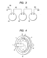
- Fig. 4 is a perspective view showing the structure of the rotating angle detector.
- 1 denotes a rotor
- 2 denotes a permanent magnet
- 3 denotes a stator
- 4 denotes a magnetic sensor.
- the permanent magnet 2 is fixed to the rotor 1 and the magnetic sensor 4 is provided on the stator 3 in a peripheral portion thereof to be opposed to the permanent magnet 2 through a gap.
- the permanent magnet 2 is magnetized in one direction perpendicularly to an axial direction as shown in an arrow by using a linear magnetic anisotropic magnet.
- the magnetic sensor 4 is provided in such a manner that each difference in mechanical phase angle is set to be 90 degrees. As a result, it is possible to obtain a sine wave and a cosine wave every rotation of the rotor 1. In the case in which the differential signals of the sine wave and the cosine wave are required, four magnetic sensors 41, 42, 43, and 44 are provided around the permanent magnet 2 to carry out a detection.
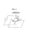
- Fig. 5 is an explanatory view showing the detection principle of the magnetic one.
- the hall sensor is formed by a compound semiconductor such as GaAs, InSb or InAs, and output terminals 5a and 5b and input current terminals 6a and 6b are attached to a magnetic sensing section having a thickness d.
- An input current I c is caused to flow to the input current terminals 6a and 6b so that a potential difference V H between the output terminals 5a and 5b is changed corresponding to a variation of magnetic flux B in magnetic sensors.
- four magnetic sensors are provided. Therefore, a wiring shown in Fig. 6 is obtained.
- Fig. 6 is a typical diagram showing the wiring in the structure of Fig. 4.
- 5 denotes a magnetic sensor terminal
- 6 denotes an input current terminal
- 10 denotes a rotation detector.
- a rotating angle can be detected by calculating a signal sent from the magnetic sensor by means of an angle calculator which is not shown.
- the invention provides a rotating angle detector comprising magnetic field generating means for rotating integrally with a detected member and uniformly generating a magnetic field in one direction perpendicularly to a rotating axis in a stationary state, and at least two magnetic sensors provided to generate one sine wave for one rotation of the magnetic field generating means respectively, wherein an input current terminal of the magnetic sensor is connected in series.
- At least two signal differential amplifying means may be arranged on a substrate provided with the magnetic sensor and there may be provided a circuit wiring in which an output sent from each of the magnetic sensors passes through the signal differential amplifying means.
- a rotating angle detecting apparatus providedwith a plurality of rotating angle detectors comprising magnetic field generating means for rotating integrally with a detected member and uniformly generating a magnetic field in one direction perpendicularly to a rotating axis in a stationary state, and at least two magnetic sensors provided to generate one sine wave for one rotation of the magnetic field generating means respectively, all input current terminals of the magnetic sensor are connected in series.
- a waveform processing apparatus for converting a signal obtained from the magnetic sensor into angular information and positional information.
- the input current path of the magnetic sensor is connected in series, and furthermore, the output signal is differentially amplified and synthesized. Consequently, there can be produced an advantage that the number of the wirings of the rotating angle detector can be decreased considerably, and at the same time, it is possible to obtain a rotating angle detector capable of having a high efficient workability also in the case in which a plurality of rotating angle detectors are used or are small-sized.
- Fig. 1 is a wiring diagram showing a magnetic sensor according to a first embodiment of the invention.
- a whole structure according to the embodiment is the same as that in Fig. 4.
- 41, 42, 43 and 44 denote a magnetic sensor
- 51, 52, 53 and 54 denote a magnetic field detecting terminal of the magnetic sensor
- 61, 62, 63 and 64 denote an input current terminal of the magnetic sensor
- 601 and 602 denote an input current path
- 10 denotes a rotating angle detector.
- Each magnetic sensor uses a hall element.
- a voltage is generated between V H and V L terminals according to the intensity of an external magnetic field. Therefore, the i L terminal of the input current terminal 61 of the magnetic sensor 41 and the i H terminal of the input current terminal 62 of the magnetic sensor 42, the i L terminal of the input current terminal 62 and the i H terminal of the input current terminal 63, and the i L terminal of the input current terminal 63 and the i H terminal of the input current terminal 64 are connected, respectively.
- the i H terminal of the input current terminal 61 is connected to the input current path 601 and the i L terminal of the input current terminal 64 is connected to the input current path 602.
- a plurality of hall elements have input current terminals connected in series.
- the total number of wirings required for the rotating angle detector 10 is ten, that is, the number of the input current terminals is two and the number of the V H and V L terminals of each magnetic sensor is eight, which is much smaller than sixteen in the conventional art.
- Fig. 2 is a wiring diagram showing a magnetic sensor according to a second embodiment of the invention.
- 601 and 602 denote an input current path
- 71, 72, 73, 74, 75 and 76 denote signal differential amplifying means (hereinafter referred to as an operational amplifier)
- 8 denotes a ground line
- 91 and 92 denote a final output of the operational amplifier
- 10 denotes a rotating angle detector.
- an i H terminal of an input current terminal 61 is connected to the input current path 601 and an i L terminal of an input current terminal 64 is connected to the input current path 602.
- the operational amplifiers 71, 72, 73, 74, 75 and 76 are provided on the same substrate as magnetic sensors 41, 42, 43 and 44, and the signals of the output terminals V H and V L of each magnetic sensor are differentially amplified by using the operational amplifiers 71, 72, 73 and 74.
- the output 91 having an A 1 phase and an output 93 having an A 2 phase are further amplified differentially to be the final output 91 by using the operational amplifiers 75 and 76, and the B 1 -phase output 92 and a B 2 -phase output 94 are differentially amplified.
- Fig. 3 is a wiring diagram showing a magnetic sensor according to a third embodiment of the invention.
- 61 to 66 denote an input current terminal of a magnetic sensor of each rotating angle detector
- 601 to 606 denote an input current path for connecting the input current terminals
- 10a, 10b and 10c denote a rotating angle detector.
- An i H terminal of the input current terminal of each rotation detector is represented as 61, 63 and 65
- an i L terminal is represented as 62, 64 and 66.
- the i L terminals and the i L terminals, for example, 62 and 63, and 64 and 65 are connected to each other. Consequently, a plurality of rotating angle detectors can be connected in series.
- two wirings for an input current can also be provided in a rotating angle detecting apparatus having a plurality of rotating angle detectors.
- the invention includes the case in which the magnetro-reluctance effect element is used as the magnetic sensor.
- the rotating angle detector may be provided with a waveform processing apparatus for converting a signal obtained from the magnetic sensor into angular information and positional information.
- the input current path of a magnetic sensor is connected in series, and furthermore, an output signal is differentially amplified and synthesized. Therefore, there can be produced an advantage that the number of the wirings of the rotating angle detector can be decreased considerably, and at the same time, it is possible to obtain a rotating angle detector capable of having a high efficient workability also in the case in which a plurality of rotating angle detectors are used or are small-sized.
Landscapes
- Physics & Mathematics (AREA)
- General Physics & Mathematics (AREA)
- Transmission And Conversion Of Sensor Element Output (AREA)
- Measurement Of Length, Angles, Or The Like Using Electric Or Magnetic Means (AREA)
Abstract
Description
Claims (4)
- A rotating angle detector comprising: magnetic field generating means for rotating integrally with a detected member and uniformly generating a magnetic field in one direction perpendicularly to a rotating axis in a stationary state, and at least two magnetic sensors provided to generate one sine wave for one rotation of the magnetic field generating means respectively,
wherein input current terminals of the magnetic sensor are connected in series. - A rotating angle detector as described in claim 1, wherein at least two signal differential amplifying means are arranged on a substrate provided with the magnetic sensor so that a circuit wiring in which an output sent from each of the magnetic sensors passes through the signal differential amplifying means.
- A rotating angle detector provided with a plurality of rotating angle detectors comprising: magnetic field generating means for rotating integrally with a detected member and uniformly generating a magnetic field in one direction perpendicularly to a rotating axis in a stationary state, and at least two magnetic sensors provided to generate one sine wave for one rotation of the magnetic field generating means respectively, wherein all input current terminals of the magnetic sensor are connected in series.
- A rotating angle detector as described in any one of claims 1 to 3, wherein a waveform processing apparatus is provided for converting a signal obtained from the magnetic sensor into angular information and positional information.
Applications Claiming Priority (3)
| Application Number | Priority Date | Filing Date | Title |
|---|---|---|---|
| JP2001036259A JP2002243407A (en) | 2001-02-14 | 2001-02-14 | Rotation angle detector and its device |
| JP2001036259 | 2001-02-14 | ||
| PCT/JP2002/001167 WO2002065051A1 (en) | 2001-02-14 | 2002-02-12 | Rotating angle detector and device using the detector |
Publications (3)
| Publication Number | Publication Date |
|---|---|
| EP1371937A1 true EP1371937A1 (en) | 2003-12-17 |
| EP1371937A4 EP1371937A4 (en) | 2005-12-14 |
| EP1371937B1 EP1371937B1 (en) | 2008-01-23 |
Family
ID=18899555
Family Applications (1)
| Application Number | Title | Priority Date | Filing Date |
|---|---|---|---|
| EP02711481A Expired - Lifetime EP1371937B1 (en) | 2001-02-14 | 2002-02-12 | Rotating angle detector and device using the detector |
Country Status (5)
| Country | Link |
|---|---|
| US (1) | US6937008B2 (en) |
| EP (1) | EP1371937B1 (en) |
| JP (1) | JP2002243407A (en) |
| DE (1) | DE60224785T2 (en) |
| WO (1) | WO2002065051A1 (en) |
Cited By (1)
| Publication number | Priority date | Publication date | Assignee | Title |
|---|---|---|---|---|
| CN107063310A (en) * | 2015-11-05 | 2017-08-18 | 英飞凌科技股份有限公司 | The redundancy magnetic degree sensor of accuracy with raising |
Families Citing this family (15)
| Publication number | Priority date | Publication date | Assignee | Title |
|---|---|---|---|---|
| EP1830162B1 (en) | 2004-12-14 | 2015-04-01 | NTN Corporation | Rotation detecting apparatus and bearing provided with same |
| JP4553714B2 (en) * | 2004-12-14 | 2010-09-29 | Ntn株式会社 | Rotation detection device and bearing with rotation detection device |
| JP4552698B2 (en) * | 2005-03-08 | 2010-09-29 | 株式会社デンソー | Magnetic detector |
| JP4390741B2 (en) * | 2005-04-14 | 2009-12-24 | 株式会社デンソー | Current sensor device |
| JP5002917B2 (en) * | 2005-06-30 | 2012-08-15 | 株式会社デンソー | Rotation angle detector |
| DE202005016726U1 (en) * | 2005-10-24 | 2007-03-01 | Rema Lipprandt Gmbh & Co. Kg | Driving switch for controlling a traction drive of a power-driven industrial truck |
| JP4589410B2 (en) | 2005-12-16 | 2010-12-01 | 旭化成エレクトロニクス株式会社 | Position detection device |
| US7884600B2 (en) | 2006-01-06 | 2011-02-08 | Ntn Corporation | Rotation angle detector and bearing with rotation angle detector |
| US7898245B2 (en) | 2006-05-12 | 2011-03-01 | Kabushiki Kaisha Yaskawa Denki | Magnetic encoder |
| JPWO2008059914A1 (en) * | 2006-11-17 | 2010-03-04 | アルプス電気株式会社 | Magnetic detector and electronic apparatus using the same |
| JP2010062683A (en) * | 2008-09-01 | 2010-03-18 | Smk Corp | Remote control transmitter |
| JP5343691B2 (en) * | 2009-05-11 | 2013-11-13 | 株式会社ニコン | Magnetic rotation angle detector and encoder |
| US8729892B2 (en) | 2011-04-01 | 2014-05-20 | Allegro Microsystems, Llc | Differential magnetic field sensor structure for orientation independent measurement |
| CN103075957B (en) * | 2013-01-09 | 2015-06-17 | 伍国伟 | Hall type angle transducer with stable structure |
| US9605975B2 (en) | 2015-06-05 | 2017-03-28 | Allegro Micorsystems, Llc | Magnetic field sensor for orientation independent speed and direction measurement |
Family Cites Families (14)
| Publication number | Priority date | Publication date | Assignee | Title |
|---|---|---|---|---|
| US2536805A (en) * | 1947-08-16 | 1951-01-02 | Gen Electric | Hall effect telemetering transmitter |
| US3146318A (en) * | 1959-12-12 | 1964-08-25 | Siemens Ag | Sound-track reproducer for motionpicture projectors |
| DE2900547C2 (en) * | 1979-01-08 | 1981-10-01 | Siemens AG, 1000 Berlin und 8000 München | Control signal generator for the commutation device of a brushless electronic motor |
| US4283664A (en) * | 1979-12-21 | 1981-08-11 | Siemens Aktiengesellschaft | Control signal generator for the commutating device of a brushless electronics motor |
| US4737710A (en) * | 1983-01-27 | 1988-04-12 | Trw Inc. | Hall-effect array for sensing second spatial derivative of magnetic field |
| JPS63305783A (en) * | 1987-06-08 | 1988-12-13 | Mitsubishi Electric Corp | Brushless motor |
| JPH02174547A (en) * | 1988-12-23 | 1990-07-05 | Matsushita Electric Works Ltd | Dc brushless motor |
| US4982155A (en) * | 1989-06-29 | 1991-01-01 | Sprague Electric Company | Hall sensor with high pass hall voltage filter |
| US5045920A (en) * | 1990-06-28 | 1991-09-03 | Allegro Microsystems, Inc. | Dual-Hall ferrous-article-proximity sensor |
| DE9212159U1 (en) * | 1992-09-09 | 1993-10-07 | Siemens AG, 80333 München | Arrangement for geometry detection with Hall elements |
| EP0590222A1 (en) * | 1992-09-30 | 1994-04-06 | STMicroelectronics S.r.l. | Magnetic position sensor |
| JP3623367B2 (en) * | 1998-07-17 | 2005-02-23 | アルプス電気株式会社 | Potentiometer with giant magnetoresistive element |
| JP4239051B2 (en) * | 1999-07-19 | 2009-03-18 | 株式会社安川電機 | Magnetic encoder and motor with magnetic encoder |
| JP3705727B2 (en) * | 2000-01-25 | 2005-10-12 | シャープ株式会社 | Hall element bias circuit |
-
2001
- 2001-02-14 JP JP2001036259A patent/JP2002243407A/en active Pending
-
2002
- 2002-02-12 DE DE60224785T patent/DE60224785T2/en not_active Expired - Fee Related
- 2002-02-12 WO PCT/JP2002/001167 patent/WO2002065051A1/en not_active Ceased
- 2002-02-12 EP EP02711481A patent/EP1371937B1/en not_active Expired - Lifetime
-
2003
- 2003-08-14 US US10/640,628 patent/US6937008B2/en not_active Expired - Lifetime
Cited By (2)
| Publication number | Priority date | Publication date | Assignee | Title |
|---|---|---|---|---|
| CN107063310A (en) * | 2015-11-05 | 2017-08-18 | 英飞凌科技股份有限公司 | The redundancy magnetic degree sensor of accuracy with raising |
| CN107063310B (en) * | 2015-11-05 | 2020-03-13 | 英飞凌科技股份有限公司 | Redundant magnetic angle sensor with improved accuracy |
Also Published As
| Publication number | Publication date |
|---|---|
| WO2002065051A1 (en) | 2002-08-22 |
| DE60224785D1 (en) | 2008-03-13 |
| EP1371937A4 (en) | 2005-12-14 |
| DE60224785T2 (en) | 2008-06-05 |
| EP1371937B1 (en) | 2008-01-23 |
| US20040150391A1 (en) | 2004-08-05 |
| US6937008B2 (en) | 2005-08-30 |
| JP2002243407A (en) | 2002-08-28 |
Similar Documents
| Publication | Publication Date | Title |
|---|---|---|
| US6937008B2 (en) | Rotating angle detector and apparatus thereof for detecting the rotating position of a rotor | |
| JP4836058B2 (en) | Magnetic encoder device | |
| JP4324813B2 (en) | Rotation angle detector and rotating machine | |
| JP4900837B2 (en) | Rotation angle detector and rotating machine | |
| US8664943B2 (en) | Position detecting apparatus | |
| JP4858855B2 (en) | Rotation angle detector and rotating machine | |
| CN1236285C (en) | Magnetic encoder | |
| US7671585B2 (en) | Rotation angle detecting device with a selecting means for selecting a pair of output signals of the magneto-sensing elements | |
| JPWO2009099054A1 (en) | Rotation angle detection device, rotator, and rotation angle detection method | |
| JPH0587512A (en) | Multiple-displacement detection device | |
| CN114413749A (en) | Magnetic field sensing device and magnetic field sensing method | |
| JP5724326B2 (en) | Rolling bearings with sensors and automobiles, railway vehicles, steelmaking facilities, machine tools using rolling bearings with sensors | |
| JPWO2007055135A1 (en) | Magnetic encoder device | |
| US6218750B1 (en) | Driving device for polyphase motor | |
| WO2009084346A1 (en) | Magnetic encoder | |
| CN117394609B (en) | Permanent magnet synchronous servo motor and electrical equipment | |
| CN224083375U (en) | Motor angle detection device based on hall sensor | |
| JP3132019B2 (en) | Rotation detection device | |
| JP4899410B2 (en) | Magnetic encoder device | |
| JPH03276014A (en) | Magnetic rotation angle detector | |
| JPH06216432A (en) | Magnetic flux density detector | |
| JP4775758B2 (en) | Magnetic encoder device | |
| JPS61189166A (en) | Small-sized motor with magnetoelectric element | |
| JPH09126711A (en) | Magnetic angle detector | |
| JPH08101222A (en) | Magnetic rotation sensor device |
Legal Events
| Date | Code | Title | Description |
|---|---|---|---|
| PUAI | Public reference made under article 153(3) epc to a published international application that has entered the european phase |
Free format text: ORIGINAL CODE: 0009012 |
|
| 17P | Request for examination filed |
Effective date: 20030915 |
|
| AK | Designated contracting states |
Kind code of ref document: A1 Designated state(s): AT BE CH CY DE DK ES FI FR GB GR IE IT LI LU MC NL PT SE TR |
|
| A4 | Supplementary search report drawn up and despatched |
Effective date: 20051031 |
|
| 17Q | First examination report despatched |
Effective date: 20060912 |
|
| GRAP | Despatch of communication of intention to grant a patent |
Free format text: ORIGINAL CODE: EPIDOSNIGR1 |
|
| RBV | Designated contracting states (corrected) |
Designated state(s): DE |
|
| GRAS | Grant fee paid |
Free format text: ORIGINAL CODE: EPIDOSNIGR3 |
|
| RIN1 | Information on inventor provided before grant (corrected) |
Inventor name: NAGASE, TAKASHI C/O K. K. YASKAWA DENKI Inventor name: MATSUZAKI, KAZUNARI C/O K. K. YASKAWA DENKI |
|
| GRAA | (expected) grant |
Free format text: ORIGINAL CODE: 0009210 |
|
| AK | Designated contracting states |
Kind code of ref document: B1 Designated state(s): DE |
|
| REF | Corresponds to: |
Ref document number: 60224785 Country of ref document: DE Date of ref document: 20080313 Kind code of ref document: P |
|
| PLBE | No opposition filed within time limit |
Free format text: ORIGINAL CODE: 0009261 |
|
| STAA | Information on the status of an ep patent application or granted ep patent |
Free format text: STATUS: NO OPPOSITION FILED WITHIN TIME LIMIT |
|
| 26N | No opposition filed |
Effective date: 20081024 |
|
| PGFP | Annual fee paid to national office [announced via postgrant information from national office to epo] |
Ref country code: DE Payment date: 20090206 Year of fee payment: 8 |
|
| PG25 | Lapsed in a contracting state [announced via postgrant information from national office to epo] |
Ref country code: DE Free format text: LAPSE BECAUSE OF NON-PAYMENT OF DUE FEES Effective date: 20100901 |