EP1371933A1 - Dispositif de raccordement entre un connecteur et une embase d'un initiateur pyrotechnique - Google Patents
Dispositif de raccordement entre un connecteur et une embase d'un initiateur pyrotechnique Download PDFInfo
- Publication number
- EP1371933A1 EP1371933A1 EP03291369A EP03291369A EP1371933A1 EP 1371933 A1 EP1371933 A1 EP 1371933A1 EP 03291369 A EP03291369 A EP 03291369A EP 03291369 A EP03291369 A EP 03291369A EP 1371933 A1 EP1371933 A1 EP 1371933A1
- Authority
- EP
- European Patent Office
- Prior art keywords
- adapter
- base
- connection device
- connector
- initiator
- Prior art date
- Legal status (The legal status is an assumption and is not a legal conclusion. Google has not performed a legal analysis and makes no representation as to the accuracy of the status listed.)
- Withdrawn
Links
- 239000003999 initiator Substances 0.000 title claims description 39
- 230000000295 complement effect Effects 0.000 claims description 3
- 230000002093 peripheral effect Effects 0.000 claims description 3
- 239000007787 solid Substances 0.000 abstract 1
- 239000011324 bead Substances 0.000 description 2
- 238000005304 joining Methods 0.000 description 2
- 239000000463 material Substances 0.000 description 2
- 239000002184 metal Substances 0.000 description 2
- 239000000203 mixture Substances 0.000 description 2
- 238000003466 welding Methods 0.000 description 2
- 239000004952 Polyamide Substances 0.000 description 1
- 230000004308 accommodation Effects 0.000 description 1
- 210000003323 beak Anatomy 0.000 description 1
- 239000004020 conductor Substances 0.000 description 1
- 238000002788 crimping Methods 0.000 description 1
- 238000010304 firing Methods 0.000 description 1
- 230000000977 initiatory effect Effects 0.000 description 1
- 238000002347 injection Methods 0.000 description 1
- 239000007924 injection Substances 0.000 description 1
- 230000010354 integration Effects 0.000 description 1
- 238000012423 maintenance Methods 0.000 description 1
- 238000004519 manufacturing process Methods 0.000 description 1
- 239000004033 plastic Substances 0.000 description 1
- 229920002647 polyamide Polymers 0.000 description 1
- 239000004417 polycarbonate Substances 0.000 description 1
- 229920000515 polycarbonate Polymers 0.000 description 1
- 239000000126 substance Substances 0.000 description 1
- 210000002105 tongue Anatomy 0.000 description 1
- 238000002604 ultrasonography Methods 0.000 description 1
Images

Classifications
-
- H—ELECTRICITY
- H01—ELECTRIC ELEMENTS
- H01R—ELECTRICALLY-CONDUCTIVE CONNECTIONS; STRUCTURAL ASSOCIATIONS OF A PLURALITY OF MUTUALLY-INSULATED ELECTRICAL CONNECTING ELEMENTS; COUPLING DEVICES; CURRENT COLLECTORS
- H01R13/00—Details of coupling devices of the kinds covered by groups H01R12/70 or H01R24/00 - H01R33/00
- H01R13/66—Structural association with built-in electrical component
- H01R13/70—Structural association with built-in electrical component with built-in switch
- H01R13/703—Structural association with built-in electrical component with built-in switch operated by engagement or disengagement of coupling parts, e.g. dual-continuity coupling part
- H01R13/7031—Shorting, shunting or bussing of different terminals interrupted or effected on engagement of coupling part, e.g. for ESD protection, line continuity
- H01R13/7032—Shorting, shunting or bussing of different terminals interrupted or effected on engagement of coupling part, e.g. for ESD protection, line continuity making use of a separate bridging element directly cooperating with the terminals
-
- F—MECHANICAL ENGINEERING; LIGHTING; HEATING; WEAPONS; BLASTING
- F42—AMMUNITION; BLASTING
- F42B—EXPLOSIVE CHARGES, e.g. FOR BLASTING, FIREWORKS, AMMUNITION
- F42B3/00—Blasting cartridges, i.e. case and explosive
- F42B3/10—Initiators therefor
- F42B3/18—Safety initiators resistant to premature firing by static electricity or stray currents
- F42B3/182—Safety initiators resistant to premature firing by static electricity or stray currents having shunting means
-
- F—MECHANICAL ENGINEERING; LIGHTING; HEATING; WEAPONS; BLASTING
- F42—AMMUNITION; BLASTING
- F42C—AMMUNITION FUZES; ARMING OR SAFETY MEANS THEREFOR
- F42C19/00—Details of fuzes
- F42C19/06—Electric contact parts specially adapted for use with electric fuzes
-
- B—PERFORMING OPERATIONS; TRANSPORTING
- B60—VEHICLES IN GENERAL
- B60R—VEHICLES, VEHICLE FITTINGS, OR VEHICLE PARTS, NOT OTHERWISE PROVIDED FOR
- B60R21/00—Arrangements or fittings on vehicles for protecting or preventing injuries to occupants or pedestrians in case of accidents or other traffic risks
- B60R21/02—Occupant safety arrangements or fittings, e.g. crash pads
- B60R21/16—Inflatable occupant restraints or confinements designed to inflate upon impact or impending impact, e.g. air bags
- B60R21/26—Inflatable occupant restraints or confinements designed to inflate upon impact or impending impact, e.g. air bags characterised by the inflation fluid source or means to control inflation fluid flow
- B60R2021/26029—Ignitors
Definitions
- the technical field of the invention is that of electrical connectors for components or initiators fireworks.
- Known pyrotechnic initiators include at least two pins intended to cooperate with a connector allowing to bring the firing current to the initiator.
- the patent FR-2807155 thus describes an initiator pyrotechnic whose housing includes a base having a cavity inside which the pins extend of connection. The cavity allows to receive a connector or an electrical component such as a shunt ring.
- the connector is made integral with the base for example using a deformable elastic spout secured to the base and which cooperates with the connector.
- Patent EP600791 describes such a pyrotechnic initiator comprising two deformable legs.
- each initiator is designed to receive a connector and / or a shunt component of given dimensions. He is not possible to connect such an initiator with a connector or a shunt component of different dimensions.
- the manufacturer of pyrotechnic initiators is therefore leads to define different product ranges in depending on the connection standards used.
- connection standards differ by one automaker to another.
- the ranges of initiators pyrotechnics must therefore be multiplied to satisfy customer needs which increases the costs of production.
- the subject of the invention is a device for connection between a connector and a base of a pyrotechnic initiator device characterized in that it includes an adapter with a profile on the one hand external intended to cooperate with a complementary profile produced on a housing of the initiator base and on the other hand an internal cavity intended to receive a connector and / or a shunt ring, the adapter comprising also the first means ensuring its integration with the base.
- the first means of securing the adapter may include at least one tab integral with the external profile of the adapter and cooperating with at least one elastically deformable lug carried by the base.
- the profile of the adapter is generally cylindrical and the adapter includes means ensuring its positioning angular with respect to the housing of the base.
- the positioning means of the adapter may include at least one peripheral projection intended to cooperate with a notch carried by the base.
- the internal cavity of the adapter will advantageously have a profile allowing to receive a shunt component.
- the internal cavity of the adapter may have a profile generally cylindrical.
- the adapter may include second means ensuring the connection of the shunt component and the adapter.
- the adapter may have at least one tab elastically deformable and allowing the locking of the connector.
- the second means of solidarity carried by the adapter may consist of at least one spout integral with the tab and cooperating with the shunt component.
- the adapter may include means allowing ensure the angular positioning of the shunt component.
- the means carried by the adapter and ensuring the angular positioning of a shunt component can be formed by a rib arranged at a surface bottom of the adapter's internal cavity.
- an initiator pyrotechnic 1 includes a pyrotechnic composition (not shown) arranged inside a housing 2 composed a substantially cylindrical case 4, made for example in metal and extended by two pins 7a, 7b.
- a pyrotechnic composition (not shown) arranged inside a housing 2 composed a substantially cylindrical case 4, made for example in metal and extended by two pins 7a, 7b.
- a substantially cylindrical case 4 made for example in metal and extended by two pins 7a, 7b.
- This case 2 is arranged inside an envelope formed by the joining of two parts: a base 16 and an upper shell 17.
- the shell and the base are produced here by injection a plastic material, for example of the polyamide type or polycarbonate. They are made integral of one another for example by ultrasonic welding.
- the base 16 has a bearing face 18 on which is made a circular groove 19 and it is crossed by two holes 20, 21 connected by a notch 22.
- the holes 20 and 21 are intended to let the pins 7a and 7b of the housing 2.
- the notch 22 allows receive the bends of pins 7a and 7b.
- the upper shell 17 has a bearing face which has a circular toothing intended to cooperate with the groove 19 of base 16.
- the upper shell 17 defines a cylindrical volume internal 28 which is intended to receive the housing 2. This volume therefore has the same diameter as the outer diameter of the housing 2 and it has a height equal to that of the case.
- the thickness e of the upper shell is of the order of 0.5 mm. This shell is thin enough to be able be broken by the initiation of the pyrotechnic composition contained in case 2.
- the base 16 also includes a housing 40 to inside which extend the pins 7a, 7b. This accommodation to a cylindrical profile and it is intended to receive a 11 mm diameter standard shunt ring (according to standard French CF BNA / F-0306 C N51).
- the base 16 and the upper shell 17 of another material, for example metal example.
- the attachment of the shell 17 on the base can then be carried out by any appropriate means (crimping, bonding, welding ).
- connection device which allows to connect a connector 3 with the base 16 of the initiator 1. For the clarity of FIG. 1, connector 3 is shown disconnected.
- This connection device consists of a adapter 5 which here comprises a cylindrical wall 5a, adjusted to the housing 40 (diameter 11 mm) of the base 16, and a background 5b.
- This adapter 5 receives a shunt component 6 of the type known as standard 10mm diameter (see in particular the content of FR2807155).
- a shunt component 6 of the type known as standard 10mm diameter (see in particular the content of FR2807155).
- Such a component has two strips conductors 8a and 8b electrically connected to each other and which make it possible to short-circuit pins 7a and 7b when connector 3 is not in place.
- the thickness of the cylindrical wall of the adapter 5 will be chosen so as to allow the establishment of the shunt component 6 and connector 3.
- Figure 1 is schematic and does not represent all of the structural details of adapter 5 and shunt component 6. These details are shown more precisely on the Figures 2 to 6.
- a base 16 for this initiator having a housing 40 of dimensions such that it can directly receive a first type of connector (with possibly a shunt component) or a second type smaller connector with interposition of a adapter and / or a shunt component.
- Such an initiator can then be compatible with different connector standards on the market: as an example, we could define the base so that its housing 40 can receive a standard shunt component 11mm (external diameter of the shunt component).
- Such a base can then also receive a 10mm standard shunt component with the interposition of a adapter 5 having 1mm thickness.
- FIGS 6a, 6b and 6c show the adapter 5 alone.
- This adapter comprises a cylindrical wall 5a and a background 5b.
- the bottom 5b is pierced with two holes 9a, 9b intended for receive pins 7a and 7b from the initiator.
- the cavity internal 10 of adapter 5 is cylindrical and is shaped to receive a shunt component 6.
- the bottom 5b of the adapter has two tabs 11a, 11b which are elastically deformable.
- Each leg has a bead 12, arranged at an internal face of the leg, and which is arranged opposite the other leg.
- the two tabs ensure the locking of the connector, the bead 12 providing resistance to extracting the connector.
- Each tab 11a, 11b carries at its end upper a beak 13 which is oriented radially in a opposite direction to where the other leg is.
- This spout 13 is intended to cooperate with the shunt component 6 to secure the connection thereof with adapter 5.
- FIG. 3 thus shows the cooperation of the spouts 13 with a notch 15 carried by the shunt component 6.
- the notch 15 is more particularly visible in FIG. 5.
- the cylindrical wall 5a of the adapter 5 has on its external surface two tongues 14 which are intended to each cooperate with an elastically deformable lug and worn by the initiator.
- Figure 4 shows the cooperation of the tabs 14 with the pins 23.
- the cylindrical wall 5a of the adapter 5 comprises also two peripheral projections 24. Each projection 24 is intended to cooperate with a notch 25 of form complementary fitted on the base 16 of the initiator (see also Figures 2 and 5).
- the projections 24 constitute means allowing ensure the angular positioning of the support 5 by relative to the housing 40 of the base 16 of the initiator.
- the projections 24 are not placed symmetrically one on the other relative to the axis of the support 5. This slight angular offset ensures that there is only one only way to introduce the support 5 into the housing 40.
- the adapter 5 also includes means allowing ensure the angular positioning of the shunt component 6.
- These means include a longitudinal rib 26 which is arranged at the bottom surface of the cavity internal 10 of the adapter (see Figures 2, 3, 4 and 6a). This rib cooperates with a slot 27 carried by the shunt component 6 (see figure 5).
- FIGS 2, 3 and 4 show more precisely the structure of the different elements of the device according to the invention.
- the upper shell 17 has not been shown of the initiator but only the base 16. Furthermore the base 16 is formed here of two parts: an upper part 16a and a lower part 16b which are welded to each other by ultrasound (see Figures 3 and 4).
- connection device The mounting of the connection device according to the invention is extremely simple.
- the projections 24 provide orientation correct angle of the adapter relative to the base 16.
- the first means of solidarity constituted by the tabs 14 of the adapter ensure the locking of this last on base 16.
- the locking tabs 11a, 11b can be in solidarity with the base of the initiator and not of the adapter. We will then make a 5 ring adapter devoid of substance 5a.
- the device according to the invention allows to connect the base of an initiator having a geometry given to at least two connectors of different geometries.
Landscapes
- Engineering & Computer Science (AREA)
- General Engineering & Computer Science (AREA)
- Details Of Connecting Devices For Male And Female Coupling (AREA)
Abstract
L'invention a pour objet un dispositif assurant le raccordement entre un connecteur (3) et un initiateur pyrotechnique (1). Ce dispositif est caractérisé en ce qu'il comprend un adaptateur (5) présentant d'une part un profil externe destiné à coopérer avec un profil complémentaire réalisé sur un logement (40) de l' initiateur (1) et d'autre part une cavité interne (10) destinée à recevoir un connecteur (3), l'adaptateur (5) comprenant également des premiers moyens (14) assurant sa solidarisation avec l'initiateur (1). La cavité interne (10) peut recevoir une bague shunt (6). <IMAGE>
Description
Le domaine technique de l'invention est celui des
connecteurs électriques pour composants ou initiateurs
pyrotechniques.
Les initiateurs pyrotechniques connus comportent au moins
deux broches destinées à coopérer avec un connecteur
permettant d'amener le courant de mise à feu à l'initiateur.
Il est connu de prévoir des initiateurs pyrotechniques
comportant des moyens assurant la solidarisation du
connecteur et de l'initiateur.
Le brevet FR-2807155 décrit ainsi un initiateur
pyrotechnique dont le boítier comporte une embase présentant
une cavité à l'intérieur de laquelle s'étendent les broches
de connexion. La cavité permet de recevoir un connecteur ou
bien un composant électrique tel qu'une bague shunt.
Le connecteur est rendu solidaire de l'embase par exemple
à l'aide d'un bec élastique déformable solidaire de l'embase
et qui coopère avec le connecteur.
Il est également connu de prévoir sur l'initiateur
pyrotechnique des pattes déformables élastiquement
(généralement deux pattes) qui pincent et enserrent le
connecteur et assurent ainsi son maintien.
Le brevet EP600791 décrit un tel initiateur pyrotechnique
comprenant deux pattes déformables.
Un problème rencontré avec les initiateurs connus est que
chaque initiateur est conçu pour recevoir un connecteur et/ou
un composant shunt de dimensions données. Il n'est pas
possible de raccorder un tel initiateur avec un connecteur ou
un composant shunt de dimensions différentes.
Le fabricant d'initiateurs pyrotechniques est donc
conduit à définir des gammes de produits différentes en
fonction des standards de connectique utilisés.
Un tel problème est particulièrement présent dans le
domaine de l'automobile. En effet les véhicules incorporent
aujourd'hui de plus en plus d'initiateurs pyrotechniques pour
déclencher les systèmes de sécurité (coussins gonflables, pré
tensionneurs de ceintures...).
Or les standards de connectique diffèrent d'un
constructeur automobile à l'autre. Les gammes d'initiateurs
pyrotechniques doivent donc être multipliées pour satisfaire
les besoins des clients ce qui accroít les coûts de
production.
C'est le but de l'invention que de pallier de tels
inconvénients en proposant un dispositif de raccordement
entre une embase d'un initiateur et un connecteur et/ou une
bague shunt.
Ainsi l'invention a pour objet un dispositif de
raccordement entre un connecteur et une embase d'un
initiateur pyrotechnique dispositif caractérisé en ce qu'il
comprend un adaptateur présentant d'une part un profil
externe destiné à coopérer avec un profil complémentaire
réalisé sur un logement de l'embase de l'initiateur et
d'autre part une cavité interne destinée à recevoir un
connecteur et/ou une bague shunt, l'adaptateur comprenant
également des premiers moyens assurant sa solidarisation avec
l'embase.
Les premiers moyens de solidarisation de l'adaptateur
pourront comprendre au moins une languette solidaire du
profil externe de l'adaptateur et coopérant avec au moins un
ergot déformable élastiquement et porté par l'embase.
Selon une autre caractéristique de l'invention, le profil
externe de l'adaptateur est globalement cylindrique et
l'adaptateur comprend des moyens assurant son positionnement
angulaire par rapport au logement de l'embase.
Les moyens de positionnement de l'adaptateur pourront
comprendre au moins une saillie périphérique destinée à
coopérer avec une encoche portée par l'embase.
La cavité interne de l'adaptateur aura avantageusement un
profil permettant de recevoir un composant shunt.
La cavité interne de l'adaptateur pourra avoir un profil
globalement cylindrique.
L'adaptateur pourra comporter des seconds moyens assurant
la solidarisation du composant shunt et de l'adaptateur.
L'adaptateur pourra comporter au moins une patte
déformable élastiquement et permettant le verrouillage du
connecteur.
Les seconds moyens de solidarisation portés par
l'adaptateur pourront être constitués par au moins un bec
solidaire de la patte et coopérant avec le composant shunt.
L'adaptateur pourra comprendre des moyens permettant
d'assurer le positionnement angulaire du composant shunt.
Les moyens portés par l'adaptateur et assurant le
positionnement angulaire d'un composant shunt pourront être
constitués par une nervure aménagée au niveau d'une surface
de fond de la cavité interne de l'adaptateur.
L'invention sera mieux comprise à la lecture de la
description qui va suivre d'un mode particulier de
réalisation, description faite en référence aux dessins
annexés et dans lesquels :
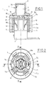
- la figure 1 est une vue schématique d'un initiateur pyrotechnique équipé d'un connecteur et d'un composant shunt et portant un dispositif de raccordement selon l'invention,
- la figure 2 est une vue de dessus d'une embase d'un initiateur portant un dispositif de raccordement selon l'invention ainsi qu'un composant shunt,
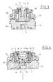
- la figure 3 est une vue en coupe longitudinale de la figure 2, la coupe est réalisée suivant le plan dont la trace AA est repérée à la figure 2,
- la figure 4 est une vue en coupe longitudinale réalisée suivant le plan dont la trace BB est repérée à la figure 2,
- la figure 5 est une vue éclatée schématisant le montage du dispositif de raccordement et du composant shunt dans l'embase de l'initiateur,
- les figures 6a, 6b et 6c sont des vues en perspectives du dispositif de raccordement représenté seul.
En se reportant à la figure 1, un initiateur
pyrotechnique 1 comprend une composition pyrotechnique (non
représentée) disposée à l'intérieur d'un boítier 2 composé
d'un étui 4 sensiblement cylindrique, réalisé par exemple en
métal et prolongé par deux broches 7a,7b. Un tel boítier
n'est pas ici décrit en détails, il est connu notamment par
le brevet FR2720493.
Ce boítier 2 est disposé à l'intérieur d'une enveloppe
formée par la solidarisation de deux parties : une embase 16
et une coquille supérieure 17.
La coquille et l'embase sont réalisées ici par injection
d'une matière plastique, par exemple du type polyamide ou
polycarbonate. Elles sont rendues solidaires l'une de l'autre
par exemple par soudure aux ultrasons.
L'embase 16 comporte une face d'appui 18 sur laquelle est
réalisé un sillon circulaire 19 et elle est traversée par
deux trous 20, 21 reliés par une entaille 22.
Les trous 20 et 21 sont destinés à laisser passer les
broches 7a et 7b du boítier 2. L'entaille 22 permet de
recevoir les courbures des broches 7a et 7b.
La coquille supérieure 17 comporte une face d'appui qui
porte une denture circulaire destinée à coopérer avec le
sillon 19 de l'embase 16.
La coquille supérieure 17 délimite un volume cylindrique
interne 28 qui est destiné à recevoir le boítier 2. Ce volume
a donc le même diamètre que le diamètre externe du boítier 2
et il a une hauteur égale à celle du boítier.
L'épaisseur e de la coquille supérieure est de l'ordre de
0,5 mm. Cette coquille est suffisamment mince pour pouvoir
être brisée par l'initiation de la composition pyrotechnique
contenue dans le boítier 2.
L'embase 16 comporte également un logement 40 à
l'intérieur duquel s'étendent les broches 7a,7b. Ce logement
à un profil cylindrique et il est destiné à recevoir une
bague shunt au standard de diamètre 11 mm (selon la norme
française CF BNA/F-0306 C N51).
Un tel initiateur est décrit par le brevet FR-2807155. Il
ne sera donc pas décrit plus en détails.
Il sera possible à titre de variante de réaliser l'embase
16 et la coquille supérieure 17 en un autre matériau, par
exemple en métal. La fixation de la coquille 17 sur l'embase
pourra alors être réalisée par tout moyen approprié
(sertissage, collage, soudure...) .
Conformément à l'invention, un dispositif de raccordement
est prévu qui permet de raccorder un connecteur 3 avec
l'embase 16 de l'initiateur 1. Pour la clarté de la figure 1,
le connecteur 3 est représenté déconnecté.
Ce dispositif de raccordement est constitué par un
adaptateur 5 qui comprend ici une paroi cylindrique 5a,
ajustée au logement 40 (diamètre 11 mm) de l'embase 16, et un
fond 5b.
Cet adaptateur 5 reçoit un composant shunt 6 de type
connu au standard diamètre 10mm (voir notamment le contenu du
brevet FR2807155). Un tel composant comporte deux lamelles
conductrices 8a et 8b reliées électriquement l'une à l'autre
et qui permettent de court-circuiter les broches 7a et 7b
lorsque le connecteur 3 n'est pas en place.
L'épaisseur de la paroi cylindrique de l'adaptateur 5
sera choisie de façon à permettre la mise en place du
composant shunt 6 et du connecteur 3.
La figure 1 est schématique et ne représente pas tous les
détails structurels de l'adaptateur 5 et du composant shunt
6. Ces détails sont représentés plus précisément sur les
figures 2 à 6.
On voit ainsi qu'il est possible de définir un initiateur
pouvant recevoir des connecteurs 3 et/ou des bagues shunt 6
de tailles différentes.
Il suffit de prévoir une embase 16 pour cet initiateur
ayant un logement 40 de dimensions telles qu'il puisse
recevoir directement un premier type de connecteur (avec
éventuellement un composant shunt) ou bien un deuxième type
de connecteur de taille plus réduite avec interposition d'un
adaptateur et/ou d'un composant shunt.
Un tel initiateur peut alors être compatible des
différents standards de connectique présents sur le marché :
on pourra à titre d'exemple définir l'embase pour que son
logement 40 puisse recevoir un composant shunt au standard
11mm (diamètre externe du composant shunt).
Une telle embase pourra alors également recevoir un
composant shunt au standard 10mm avec l'interposition d'un
adaptateur 5 ayant 1mm d'épaisseur.
Les figures 6a, 6b et 6c montrent l'adaptateur 5 seul.
Cet adaptateur comprend une paroi cylindrique 5a et un
fond 5b. Le fond 5b est percé de deux trous 9a, 9b destinés à
recevoir les broches 7a et 7b de l'initiateur. La cavité
interne 10 de l'adaptateur 5 est cylindrique et elle est
conformée pour recevoir un composant shunt 6.
Le fond 5b de l'adaptateur porte deux pattes 11a, 11b qui
sont déformables élastiquement. Chaque patte porte un
bourrelet 12, aménagé au niveau d'une face interne de la
patte, et qui est disposé en regard de l'autre patte. Les
deux pattes permettent d'assurer le verrouillage du
connecteur, le bourrelet 12 opposant une résistance à
l'extraction du connecteur.
Chaque patte 11a, 11b porte au niveau de son extrémité
supérieure un bec 13 qui est orienté radialement dans une
direction opposée à celle où se trouve l'autre patte.
Ce bec 13 est destiné à coopérer avec le composant shunt
6 pour assurer la solidarisation de celui ci avec
l'adaptateur 5.
La figure 3 montre ainsi la coopération des becs 13 avec
une encoche 15 portée par le composant shunt 6. L'encoche 15
est plus particulièrement visible sur la figure 5.
La paroi cylindrique 5a de l'adaptateur 5 comporte sur sa
surface externe deux languettes 14 qui sont destinées à
coopérer chacune avec un ergot déformable élastiquement et
porté par l'initiateur.
La figure 4 montre la coopération des languettes 14 avec
les ergots 23.
La paroi cylindrique 5a de l'adaptateur 5 comporte
également deux saillies périphériques 24. Chaque saillie 24
est destinée à coopérer avec une encoche 25 de forme
complémentaire aménagée sur l'embase 16 de l'initiateur (voir
également les figures 2 et 5).
Les saillies 24 constituent des moyens permettant
d'assurer le positionnement angulaire du support 5 par
rapport au logement 40 de l'embase 16 de l'initiateur.
Comme cela est plus particulièrement visible à la figure
2, les saillies 24 ne sont pas placées symétriquement l'une
de l'autre par rapport à l'axe du support 5. Ce léger
décalage angulaire permet d'assurer qu'il n'existe qu'une
seule façon d'introduire le support 5 dans le logement 40.
L'adaptateur 5 comprend également des moyens permettant
d'assurer le positionnement angulaire du composant shunt 6.
Ces moyens comprennent une nervure 26 longitudinale qui
est aménagée au niveau de la surface de fond de la cavité
interne 10 de l'adaptateur (voir figures 2, 3, 4 et 6a).
Cette nervure coopère avec une fente 27 portée par le
composant shunt 6 (voir figure 5).
Les figures 2, 3 et 4 montrent de façon plus précise la
structure des différents éléments du dispositif selon
l'invention.
On notera que dans le mode de réalisation présenté sur
ces figures, on n'a pas représenté la coquille supérieure 17
de l'initiateur mais seule l'embase 16. Par ailleurs l'embase
16 est formée ici de deux parties : une partie supérieure 16a
et une partie inférieure 16b qui sont soudées l'une à l'autre
par ultra sons (voir figures 3 et 4).
Le montage du dispositif de raccordement selon
l'invention est extrêmement simple.
On place tout d'abord l'adaptateur 5 dans la cavité
interne 40 de l'embase 16 (voir figure 5).
Les saillies 24 permettent d'assurer une orientation
angulaire correcte de l'adaptateur par rapport à l'embase 16.
Les premiers moyens de solidarisation constitués par les
languettes 14 de l'adaptateur assurent le verrouillage de ce
dernier sur l'embase 16.
On introduit ensuite le composant shunt 6 dans
l'adaptateur 5. Le bon positionnement angulaire du shunt est
assuré par la nervure 26 qui coopère avec la fente 27.
Les seconds moyens de solidarisation portés par
l'adaptateur et qui sont constitués par les becs 13 portés
par les pattes 11a, 11b assurent le verrouillage relatif de
l'adaptateur avec le composant shunt.
Il sera possible alors d'introduire un connecteur 3 dans
le composant shunt 6. Les pattes 11a, 11b assureront le
verrouillage du connecteur avec l'initiateur.
Différentes variantes sont possibles sans sortir du cadre
de l'invention.
Il est possible ainsi de réaliser des adaptateurs ayant
des formes ou profils différents pour pouvoir s'adapter à des
connecteurs de formes différentes.
Les pattes de verrouillage 11a, 11b pourront être
solidaires de l'embase de l'initiateur et non de
l'adaptateur. On réalisera alors un adaptateur 5 annulaire
dépourvu de fond 5a.
On pourra modifier les formes des moyens assurant
verrouillage ou positionnement de l'adaptateur.
On pourra également définir un adaptateur qui incorpore
les moyens assurant la fonction du composant shunt (lamelles
8a, 8b).
On pourra définir un adaptateur permettant la mise en
place d'un connecteur donné sans interposition d'un composant
shunt.
Dans tous les cas le dispositif selon l'invention permet
de raccorder l'embase d'un initiateur ayant une géométrie
donnée à au moins deux connecteurs de géométries différentes.
On pourra enfin définir pour un initiateur donné
plusieurs modèles d'adaptateurs permettant de raccorder
l'initiateur à plus de deux connecteurs différents.
Claims (11)
- Dispositif de raccordement entre un connecteur (3) et une embase (16) d'un initiateur pyrotechnique caractérisé en ce qu'il comprend un adaptateur (5) présentant d'une part un profil externe (5a) destiné à coopérer avec un profil complémentaire réalisé sur un logement (40) de l'embase (16) de l'initiateur et d'autre part une cavité interne (10) destinée à recevoir un connecteur (3) et/ou une bague shunt (6), l'adaptateur comprenant également des premiers moyens assurant sa solidarisation avec l'embase (16).
- Dispositif de raccordement selon la revendication 1, caractérisé en ce que les premiers moyens de solidarisation de l'adaptateur comprennent au moins une languette (14) solidaire du profil externe de l'adaptateur et coopérant avec au moins un ergot (23) déformable élastiquement et porté par l'embase (16).
- Dispositif de raccordement selon une des revendications 1 ou 2, caractérisé en ce que le profil externe (5a) de l'adaptateur (5) est globalement cylindrique et en ce que l'adaptateur comprend des moyens (24) assurant son positionnement angulaire par rapport au logement de l'embase (16).
- Dispositif de raccordement selon la revendication 3, caractérisé en ce que les moyens de positionnement de l'adaptateur comprennent au moins une saillie périphérique (24) destinée à coopérer avec une encoche (25) portée par l'embase (16).
- Dispositif de raccordement selon une des revendications 1 à 4, caractérisé en ce que la cavité interne (10) de l'adaptateur a un profil permettant de recevoir un composant shunt (6).
- Dispositif de raccordement selon la revendication 5, caractérisé en ce que la cavité interne (10) de l'adaptateur a un profil globalement cylindrique.
- Dispositif de raccordement selon une des revendications 5 ou 6, caractérisé en ce que l'adaptateur comporte des seconds moyens (13) assurant la solidarisation du composant shunt (6) et de l'adaptateur (5).
- Dispositif de raccordement selon une des revendications 1 à 7, caractérisé en ce que l'adaptateur (5) comporte au moins une patte (11a, 11b) déformable élastiquement et permettant le verrouillage du connecteur.
- Dispositif de raccordement selon les revendications 7 et 8, caractérisé en ce que les seconds moyens de solidarisation portés par l'adaptateur sont constitués par au moins un bec (13) solidaire de la patte (11a, 11b) et coopérant avec le composant shunt (6).
- Dispositif de raccordement selon une des revendications 5 à 9, caractérisé en ce que l'adaptateur (5) comprend des moyens permettant d'assurer le positionnement angulaire du composant shunt (6).
- Dispositif de raccordement selon la revendication 10, caractérisé en ce que les moyens portés par l'adaptateur (5) et assurant le positionnement angulaire d'un composant shunt (6) sont constitués par une nervure (26) aménagée au niveau d'une surface de fond de la cavité interne (10) de l'adaptateur (5).
Applications Claiming Priority (2)
| Application Number | Priority Date | Filing Date | Title |
|---|---|---|---|
| FR0207071A FR2840681A1 (fr) | 2002-06-10 | 2002-06-10 | Dispositif de raccordement entre un connecteur et une embase d'un initiateur pyrotechnique |
| FR0207071 | 2002-06-10 |
Publications (1)
| Publication Number | Publication Date |
|---|---|
| EP1371933A1 true EP1371933A1 (fr) | 2003-12-17 |
Family
ID=29559069
Family Applications (1)
| Application Number | Title | Priority Date | Filing Date |
|---|---|---|---|
| EP03291369A Withdrawn EP1371933A1 (fr) | 2002-06-10 | 2003-06-06 | Dispositif de raccordement entre un connecteur et une embase d'un initiateur pyrotechnique |
Country Status (2)
| Country | Link |
|---|---|
| EP (1) | EP1371933A1 (fr) |
| FR (1) | FR2840681A1 (fr) |
Citations (3)
| Publication number | Priority date | Publication date | Assignee | Title |
|---|---|---|---|---|
| US5178547A (en) * | 1991-09-13 | 1993-01-12 | Trw Inc. | Initiator assembly with connector interface element |
| WO2001013484A2 (fr) * | 1999-08-12 | 2001-02-22 | Atlantic Research Corporation | Adaptateur de connecteur coule sous pression et ensemble de gonflage comprenant cet adaptateur |
| US6341562B1 (en) * | 2000-02-22 | 2002-01-29 | Autoliv Asp, Inc. | Initiator assembly with activation circuitry |
Family Cites Families (1)
| Publication number | Priority date | Publication date | Assignee | Title |
|---|---|---|---|---|
| FR2807155B1 (fr) | 2000-03-30 | 2003-03-21 | Giat Ind Sa | Initiateur pyrotechnique pouvant etre equipe d'un composant electrique ou electronique et/ou d'un connecteur |
-
2002
- 2002-06-10 FR FR0207071A patent/FR2840681A1/fr active Pending
-
2003
- 2003-06-06 EP EP03291369A patent/EP1371933A1/fr not_active Withdrawn
Patent Citations (3)
| Publication number | Priority date | Publication date | Assignee | Title |
|---|---|---|---|---|
| US5178547A (en) * | 1991-09-13 | 1993-01-12 | Trw Inc. | Initiator assembly with connector interface element |
| WO2001013484A2 (fr) * | 1999-08-12 | 2001-02-22 | Atlantic Research Corporation | Adaptateur de connecteur coule sous pression et ensemble de gonflage comprenant cet adaptateur |
| US6341562B1 (en) * | 2000-02-22 | 2002-01-29 | Autoliv Asp, Inc. | Initiator assembly with activation circuitry |
Also Published As
| Publication number | Publication date |
|---|---|
| FR2840681A1 (fr) | 2003-12-12 |
Similar Documents
| Publication | Publication Date | Title |
|---|---|---|
| EP1028490B1 (fr) | Raccord coaxial pour relier deux cartes de circuit imprimé | |
| EP2005869B1 (fr) | Appareil de préparation culinaire muni d'un dispositif de sécurité | |
| EP3217059A1 (fr) | Système de serrage comprenant un collier et des clips individuels de pré-montage | |
| FR2742109A1 (fr) | Dispositif pour declencher un gonfleur d'un organe de retenue d'un occupant d'un vehicule | |
| EP1158620A1 (fr) | Elément femelle de connecteur électrique | |
| EP3095684B1 (fr) | Patte de derailleur | |
| FR3030130A1 (fr) | Borne de connecteur | |
| EP1139060B1 (fr) | Initiateur pyrotechnique pouvant être équipé d'un composant électrique ou électronique et/ou d'un connecteur | |
| EP1371933A1 (fr) | Dispositif de raccordement entre un connecteur et une embase d'un initiateur pyrotechnique | |
| FR3030129A1 (fr) | Borne de connecteur | |
| EP0744088B1 (fr) | Fiche electrique du type fiche anglaise | |
| EP1444051B1 (fr) | Distributeur de produit fluide | |
| FR3061562B1 (fr) | Dispositif de raccordement amovible pour un guide de lumiere et application dans un vehicule automobile, module a transmission optique pourvu du dispositif | |
| FR2715512A1 (fr) | Connecteur pour câble coaxial. | |
| EP0468899B1 (fr) | Système de fixation démontable d'un élément par rapport à un organe fixe, ledit élément étant notamment un enjoliveur de roue de véhicule | |
| EP1449732B1 (fr) | Dispositif d'alimentation pour système de freinage, notamment pour véhicule automobile et procédé de montage d'un tel système | |
| EP1176384A2 (fr) | Initiateur pyrotechnique pouvant être équipé d'un composant éléctrique ou électronique et/ou d'un connecteur | |
| EP1205672A1 (fr) | Support de retenue souple d'un objet sur une cloison | |
| FR2604774A1 (fr) | Ensemble de liaison pour lampe de signalisation | |
| FR2807154A1 (fr) | Initiateur pyrotechnique pouvant etre equipe d'un composant electrique ou electronique et/ou d'un connecteur | |
| FR3141004A1 (fr) | Connecteur pour la fixation d’un câble sur un circuit imprimé. | |
| EP1378975B1 (fr) | Dispositif de connexion électrique insérable dans un trou borgne | |
| EP1655816A2 (fr) | Plaque en verre masquant un accessoire électrique, et appareillage électrique s'y rapportant | |
| EP0911788A1 (fr) | Dispositif d'identification | |
| FR2710882A1 (fr) | Ensemble de fixation d'une platine sur une colonne, notamment pour la fixation d'une platine de commutateur électrique sur une colonne de direction de véhicule automobile. |
Legal Events
| Date | Code | Title | Description |
|---|---|---|---|
| PUAI | Public reference made under article 153(3) epc to a published international application that has entered the european phase |
Free format text: ORIGINAL CODE: 0009012 |
|
| AK | Designated contracting states |
Kind code of ref document: A1 Designated state(s): AT BE BG CH CY CZ DE DK EE ES FI FR GB GR HU IE IT LI LU MC NL PT RO SE SI SK TR |
|
| AX | Request for extension of the european patent |
Extension state: AL LT LV MK |
|
| 17P | Request for examination filed |
Effective date: 20040120 |
|
| AKX | Designation fees paid |
Designated state(s): DE ES GB IT SE |
|
| STAA | Information on the status of an ep patent application or granted ep patent |
Free format text: STATUS: THE APPLICATION IS DEEMED TO BE WITHDRAWN |
|
| 18D | Application deemed to be withdrawn |
Effective date: 20060103 |