EP1371868A1 - Electronic controlled coupling - Google Patents
Electronic controlled coupling Download PDFInfo
- Publication number
- EP1371868A1 EP1371868A1 EP03012273A EP03012273A EP1371868A1 EP 1371868 A1 EP1371868 A1 EP 1371868A1 EP 03012273 A EP03012273 A EP 03012273A EP 03012273 A EP03012273 A EP 03012273A EP 1371868 A1 EP1371868 A1 EP 1371868A1
- Authority
- EP
- European Patent Office
- Prior art keywords
- wet
- multiple disc
- type multiple
- disc clutch
- electronic controlled
- Prior art date
- Legal status (The legal status is an assumption and is not a legal conclusion. Google has not performed a legal analysis and makes no representation as to the accuracy of the status listed.)
- Granted
Links
- 230000008878 coupling Effects 0.000 title claims abstract description 89
- 238000010168 coupling process Methods 0.000 title claims abstract description 89
- 238000005859 coupling reaction Methods 0.000 title claims abstract description 89
- 238000001816 cooling Methods 0.000 claims description 18
- 230000007246 mechanism Effects 0.000 abstract description 7
- 230000002708 enhancing effect Effects 0.000 abstract description 2
- 230000005540 biological transmission Effects 0.000 description 26
- 238000003825 pressing Methods 0.000 description 8
- 238000000034 method Methods 0.000 description 7
- 230000008569 process Effects 0.000 description 7
- 230000001276 controlling effect Effects 0.000 description 5
- 238000005461 lubrication Methods 0.000 description 3
- 230000004044 response Effects 0.000 description 3
- 230000008859 change Effects 0.000 description 2
- 230000001105 regulatory effect Effects 0.000 description 2
- 230000001133 acceleration Effects 0.000 description 1
- 230000009286 beneficial effect Effects 0.000 description 1
- 238000005516 engineering process Methods 0.000 description 1
- 230000001050 lubricating effect Effects 0.000 description 1
- 239000002184 metal Substances 0.000 description 1
- 230000009467 reduction Effects 0.000 description 1
- 230000007704 transition Effects 0.000 description 1
Images


Classifications
-
- F—MECHANICAL ENGINEERING; LIGHTING; HEATING; WEAPONS; BLASTING
- F16—ENGINEERING ELEMENTS AND UNITS; GENERAL MEASURES FOR PRODUCING AND MAINTAINING EFFECTIVE FUNCTIONING OF MACHINES OR INSTALLATIONS; THERMAL INSULATION IN GENERAL
- F16D—COUPLINGS FOR TRANSMITTING ROTATION; CLUTCHES; BRAKES
- F16D25/00—Fluid-actuated clutches
- F16D25/12—Details not specific to one of the before-mentioned types
- F16D25/14—Fluid pressure control
-
- F—MECHANICAL ENGINEERING; LIGHTING; HEATING; WEAPONS; BLASTING
- F16—ENGINEERING ELEMENTS AND UNITS; GENERAL MEASURES FOR PRODUCING AND MAINTAINING EFFECTIVE FUNCTIONING OF MACHINES OR INSTALLATIONS; THERMAL INSULATION IN GENERAL
- F16D—COUPLINGS FOR TRANSMITTING ROTATION; CLUTCHES; BRAKES
- F16D25/00—Fluid-actuated clutches
- F16D25/06—Fluid-actuated clutches in which the fluid actuates a piston incorporated in, i.e. rotating with the clutch
- F16D25/062—Fluid-actuated clutches in which the fluid actuates a piston incorporated in, i.e. rotating with the clutch the clutch having friction surfaces
- F16D25/063—Fluid-actuated clutches in which the fluid actuates a piston incorporated in, i.e. rotating with the clutch the clutch having friction surfaces with clutch members exclusively moving axially
- F16D25/0635—Fluid-actuated clutches in which the fluid actuates a piston incorporated in, i.e. rotating with the clutch the clutch having friction surfaces with clutch members exclusively moving axially with flat friction surfaces, e.g. discs
- F16D25/0638—Fluid-actuated clutches in which the fluid actuates a piston incorporated in, i.e. rotating with the clutch the clutch having friction surfaces with clutch members exclusively moving axially with flat friction surfaces, e.g. discs with more than two discs, e.g. multiple lamellae
-
- F—MECHANICAL ENGINEERING; LIGHTING; HEATING; WEAPONS; BLASTING
- F16—ENGINEERING ELEMENTS AND UNITS; GENERAL MEASURES FOR PRODUCING AND MAINTAINING EFFECTIVE FUNCTIONING OF MACHINES OR INSTALLATIONS; THERMAL INSULATION IN GENERAL
- F16D—COUPLINGS FOR TRANSMITTING ROTATION; CLUTCHES; BRAKES
- F16D48/00—External control of clutches
- F16D48/02—Control by fluid pressure
-
- F—MECHANICAL ENGINEERING; LIGHTING; HEATING; WEAPONS; BLASTING
- F16—ENGINEERING ELEMENTS AND UNITS; GENERAL MEASURES FOR PRODUCING AND MAINTAINING EFFECTIVE FUNCTIONING OF MACHINES OR INSTALLATIONS; THERMAL INSULATION IN GENERAL
- F16D—COUPLINGS FOR TRANSMITTING ROTATION; CLUTCHES; BRAKES
- F16D48/00—External control of clutches
- F16D48/06—Control by electric or electronic means, e.g. of fluid pressure
- F16D48/064—Control of electrically or electromagnetically actuated clutches
-
- F—MECHANICAL ENGINEERING; LIGHTING; HEATING; WEAPONS; BLASTING
- F16—ENGINEERING ELEMENTS AND UNITS; GENERAL MEASURES FOR PRODUCING AND MAINTAINING EFFECTIVE FUNCTIONING OF MACHINES OR INSTALLATIONS; THERMAL INSULATION IN GENERAL
- F16D—COUPLINGS FOR TRANSMITTING ROTATION; CLUTCHES; BRAKES
- F16D2500/00—External control of clutches by electric or electronic means
- F16D2500/10—System to be controlled
- F16D2500/102—Actuator
- F16D2500/1021—Electrical type
- F16D2500/1023—Electric motor
- F16D2500/1024—Electric motor combined with hydraulic actuation
Definitions
- the present invention relates to electronic controlled couplings for transmitting torque with a wet-type multiple disc clutch engageable by hydraulic pressure.
- a technology is known as a power transmission system used for four-wheel drive vehicles in which a coupling mechanism, such as a multiple disc clutch or a viscous coupling, continuously controls a driving force to be distributed to the rear wheels.
- a coupling mechanism such as a multiple disc clutch or a viscous coupling
- four-wheel drive vehicles equipped with an automatic transmission can utilize a hydraulic power source of the automatic transmission; hence, many four-wheel drive vehicles of this type use a hydraulic wet-type multiple disc clutch.
- a coupling that engages a multiple disc clutch by a mechanical driving force.
- a coupling is disclosed, for example, in JP-A-2000-346102.
- an armature of an electromagnet causes a control clutch, which is a metal multiple disc clutch, to be pressed and engaged, and engaging torque of the control clutch is transmitted to a main clutch, which is a wet-type multiple disc clutch, by a cam mechanism.
- control clutch is operated by electrical signals and a pressure load of the wet-type multiple disc clutch is amplified by a mechanical cam mechanism. This causes problems of heat resistance and wear resistance of the clutch and the controllability of the clutch due to a change in the temperature of a coil.
- hydraulic wet-type multiple disc clutch If a hydraulic wet-type multiple disc clutch is used, hydraulic lubrication and cooling considerably solve the above problems. Since, however, a hydraulic power source is needed, the hydraulic wet-type multiple disc clutch of this type is applicable to limited cases. Moreover, a hydraulic circuit, various pressure-regulating valves, and the like are needed for obtaining a clutch operating pressure, thus causing restricted flexibility in designing.
- an object of the present invention to increase the durability of an electronic controlled coupling that includes a hydraulic wet-type multiple disc clutch within a complete coupling mechanism and that has a compact and simple structure and enhances the flexibility in designing.
- an oil pump driven by an electric motor is mounted to a case that accommodates a wet-type multiple disc clutch and contains oil.
- the outlet of the oil pump is connected to a hydraulic chamber of the wet-type multiple disc clutch, with a supply passage for supplying hydraulic pressure therebetween.
- the supply passage is a one-way closed circuit not having a return path from the hydraulic chamber.
- Figs. 1 to 4 show an electronic controlled coupling according to a first embodiment of the present invention.
- Fig. 1 schematically illustrates the structure of an electronic controlled coupling 1 provided in a power transmission system used for a vehicle.
- the electronic controlled coupling 1 includes a wet-type multiple disc clutch 2, a coupling case 3, an oil pump 4, an electric motor 5 (hereinafter, referred to as a motor 5), a motor driver 6, and an electric control unit 7 (hereinafter, referred to as an ECU 7), and these are integrated together.
- the wet-type multiple disc clutch 2 transmits driving torque by contacting surfaces of a plurality of alternately deposited driving plates and driven plates.
- the coupling case 3 accommodates the wet-type multiple disc clutch 2 and contains oil therein.
- the oil pump 4 is mounted to the coupling case 3, and sucks and pressurizes the oil to directly supply it to the wet-type multiple disc clutch 2.
- the motor 5 drives the oil pump 4, the motor driver 6 drives the motor 5, and the ECU 7 controls the motor driver 6.
- the coupling case 3 contains the oil for an operating hydraulic pressure and lubrication for the wet-type multiple disc clutch 2.
- the outlet of the oil pump 4 is connected to a hydraulic chamber 2a, with a supply passage 8 for supplying hydraulic pressure therebetween.
- the hydraulic chamber 2a is provided for engaging the wet-type multiple disc clutch 2.
- Driving the oil pump 4 by rotation of the motor 5 causes the oil in the coupling case 3 to be sucked and pressurized.
- the discharge pressure of the oil pump 4 directly affects the hydraulic chamber 2a of the wet-type multiple disc clutch 2.
- the supply passage 8, guiding the oil discharged from the oil pump 4 to the wet-type multiple disc clutch 2, is a one-way closed circuit not having a return path from the hydraulic chamber 2a.
- the engagement of the wet-type multiple disc clutch 2 is controlled by only adjusting the discharge pressure of the oil pump 4 under the control of the speed of rotation of the motor 5.
- a pilot circuit, a return circuit, and various regulating valves, such as a pressure-regulating valve and a relief valve, for pressure regulation are not needed.
- the ECU 7 controls the rotation of the motor 5 through the motor driver 6.
- the ECU 7 determines a running condition on the basis of signals from various sensors (not shown), such as a wheel speed sensor and an acceleration sensor, in order to determine transmission torque suitable for the resulting running condition. Then, the ECU 7 controls the speed of rotation of the motor 5 so that the discharge pressure of the oil pump 4 is equal to an operating pressure of the wet-type multiple disc clutch 2 required for generating the transmission torque.
- the motor 5 When the wet-type multiple disc clutch 2 is disengaged, the motor 5 is controlled to be in a standby mode with a rotation speed set in advance so that the discharge pressure of the oil pump 4 is less than an operating pressure for clutch engagement, for ensuring startup response.
- the ECU 7 In order to engage the wet-type multiple disc clutch 2, the ECU 7 increases the rotation speed of the motor 5 to a rotation speed that corresponds to a pump discharge pressure for generating required transmission torque.
- a release passage 9 may be provided in the middle of the supply passage 8 and that an on-off valve 10 which is opened and closed by an electromagnetic solenoid or the like may be provided in the middle of the release passage 9, as indicated by the dotted lines in Fig. 1.
- opening the on-off valve 10 in accordance with an instruction from the ECU 7 allows an improved release performance.
- reverse rotation of the motor 5 suppresses the response delay, thus drastically improving the release performance.
- Fig. 2 shows an example in which the electronic controlled coupling 1 described above is applied for a four-wheel drive vehicle equipped with a manual transmission 20 (hereinafter, referred to as a transmission 20).
- the electronic controlled coupling 1 is provided, as a transfer, at the rear of the transmission 20.
- a synchromesh mechanism 23 allows transmission gears idling on a main shaft 21 connected to an output shaft of an engine through a clutch (not shown) to be engaged with transmission gears on a drive pinion shaft 22 in accordance with gear change operation.
- the driving force of the engine transmitted to the main shaft 21 is transmitted to the front wheels from a front differential (not shown) via the drive pinion shaft 22.
- the driving force is also transmitted to a transfer driven gear 25 via a transfer driving gear 24 coupled to the rear end of the drive pinion shaft 22.
- the transfer driven gear 25 is connected to a clutch shaft 26, which is an input shaft of the electronic controlled coupling 1, and a rear wheel output shaft 27, which is an output shaft of the electronic controlled coupling 1, is connected to a rear differential (not shown) with a propeller shaft 28 therebetween. Accordingly, the driving force is distributed to the rear wheels.
- the wet-type multiple disc clutch 2 in the coupling case 3 includes a clutch drum 30 extending from the clutch shaft 26 and having a larger diameter than that of the clutch shaft 26, a clutch hub 31 coupled to a circumference of the rear wheel output shaft 27, a clutch plate unit 32 which is optionally engaged or disengaged between the clutch drum 30 and the clutch hub 31, and a piston 34 pressing the clutch plate unit 32 with a pressing member 33.
- the hydraulic chamber 2a is provided behind the piston 34. The hydraulic chamber 2a allows the wet-type multiple disc clutch 2 to be engaged by moving the piston 34 in the axial direction to transmit pressing force to the pressing member 33.
- a bearing 35 is disposed between the pressing member 33 and the piston 34.
- the bearing 35 transmits pressing force to the rotating pressing member 33 by linear movement of the piston 34.
- a return spring 36 urges the clutch plate unit 32 in the disengaging direction against the pressing force of the piston 34.
- An integrated pump unit of the oil pump 4 and the motor 5 is attached to a side wall unit 3a provided below the rear wheel output shaft 27 of the coupling case 3.
- a suction passage 37 for sucking oil and the supply passage 8 are arranged within the side wall unit 3a.
- the suction passage 37 is connected to the inlet of the oil pump 4 and is opened to the coupling case 3.
- the supply passage 8 directly connects an outlet of the oil pump 4 to the hydraulic chamber 2a of the wet-type multiple disc clutch 2.
- the transmission 20 and the electronic controlled coupling 1, functioning as a transfer, are separated from each other by an oil seal 38 arranged on the circumference of the clutch shaft 26.
- the oil in the transmission 20 is separated from the oil in the electronic controlled coupling 1.
- the same type of oil can be used in the transmission 20 and the electronic controlled coupling 1.
- the oil used in the electronic controlled coupling 1 may be different from the oil used in the transmission 20.
- Oil used in the electronic controlled coupling 1 may be selected in consideration of the characteristics of the wet-type multiple disc clutch 2 and the oil pump 4.
- the rotation of the motor 5 is controlled by the ECU 7 so that transmission toque is generated on the basis of a running condition of a vehicle, a condition of a road surface, and the like.
- the torque distribution ratio of front wheels to rear wheels is variable between 100: 0 (clutch is disengaged) and 50: 50 (clutch is engaged).
- Variably controlling the transmission torque by controlling the speed of rotation of the motor 5 pressurizes and transfers the oil discharged from the oil pump 4 directly to the hydraulic chamber 2a of the wet-type multiple disc clutch 2 so that the discharge pressure of the oil pump 4 is equal to a clutch operating pressure.
- controllability of the wet-type multiple disc clutch 2 can be improved without being affected by various hydraulic circuits, pressure-regulating valves, and the like for obtaining a clutch operating pressure.
- oil contained in the coupling case 3 lubricates and cools each portion, thus improving the durability of the electronic controlled coupling 1.
- Fig. 3 shows an example in which the electronic controlled coupling 1 is provided between the propeller shaft and a rear differential 40.
- the coupling case 3 of the electronic controlled coupling 1 extends backwards to function as part of a case for the rear differential 40.
- the clutch shaft 26, which is an input shaft of the electronic controlled coupling 1 is connected to the rear end of the propeller shaft, and the rear wheel output shaft 27, which is an output shaft of the electronic controlled coupling 1, is connected to the rear differential 40 accommodating a viscous coupling 42, with a bevel gear 41 therebetween.
- the internal structure of the electronic controlled coupling 1 is basically similar to the structure of the transfer described above with the exception that the structure around the output shaft slightly differs.
- step S101 it is determined whether or not an ignition switch (not shown) is turned on.
- Step S101 is provided for setting the electronic controlled coupling 1 to a standby mode prior to running of a vehicle. It may be determined that the electronic controlled coupling 1 is prepared for a standby mode, for example, by an "on" signal indicating that a vehicle door is opened, instead of by an "ignition-on” signal.
- step S101 When it is determined that the switch is off in step S101, motor indicating torque, which is indication torque for the motor 5, is set to zero in step S102. Thus, the electronic controlled coupling 1 is set to a non-operating state (clutch is disengaged).
- step S103 When it is determined that the switch is on in step S101, the process proceeds to step S103 to run the motor 5 in a standby mode with a rotation speed set in advance.
- step S104 it is determined whether or not front or rear wheel slip is caused on the basis of signals from the wheel speed sensor for the front and rear wheels.
- step S105 it is determined whether or not the vehicle is in a starting mode in step S105.
- starting control is performed in step S106.
- the indication torque for the motor 5 is determined in accordance with the degree of engine throttle opening. For slow starting, the discharge pressure of the oil pump 4 is increased relatively moderately so that the clutch engaging pressure is gradually increased. For quick starting, the discharge pressure of the oil pump 4 is rapidly increased so that the clutch is quickly engaged.
- step S105 When it is determined that the vehicle is not in the starting mode in step S105, the process proceeds to step S107 to determine whether or not normal control is required. When it is determined that the normal control is not required, the process returns to step S103. When it is determined that the normal control is required, the process proceeds to step S108 to perform the normal control.
- the normal control for example, the indication torque for the motor 5 is determined on the basis of the degree of throttle opening and the speed of the vehicle, and the discharge pressure of the oil pump 4 is controlled to a clutch operating pressure for generating transmission torque suitable for the running state.
- step S104 When it is determined that the front or rear wheel slip is caused in step S104, the process proceeds to step S109 to perform the slip control.
- the slip control for example, when front wheel slip is caused, the indication torque for the motor 5 is increased in accordance with the degree of the slip in order to adjust the discharge pressure of the oil pump 4, that is, the clutch engaging pressure, thus suppressing the front wheel slip.
- the electronic controlled coupling 1 includes the integrated wet-type multiple disc clutch 2, the oil pump 4, and the motor 5.
- the oil pump 4 is driven by the motor 5, and the discharge pressure of the oil pump 4 is adjusted by controlling the rotation speed of the motor 5.
- the clutch engaging pressure is controlled through the resulting discharge pressure of the oil pump 4.
- the electronic controlled coupling 1 has a compact structure and is mechanically complete as a coupling, thus enhancing flexibility in designing. Therefore, the electronic controlled coupling 1 is readily applicable to power transmission systems used for vehicles. Particularly, the electronic controlled coupling 1 is effectively used for manual transmission-equipped vehicles without their own hydraulic power source.
- the electronic controlled coupling 1 hydraulic lubrication is readily performed and heat resistance of the clutch is improved.
- the clutch operating pressure can be controlled by the control of the rotation speed of the motor 5.
- a hydraulic circuit and various regulating valves for obtaining the clutch operating pressure are not needed, thus reducing the cost.
- an electronic controlled coupling 50 includes a cooling oil passage 51 for supplying cooling oil in order to effectively cool the wet-type multiple disc clutch 2.
- the cooling oil passage 51 branches off from the midstream of the supply passage 8 for supplying hydraulic pressure. Accordingly, the wet-type multiple disc clutch 2 is forcibly cooled by the oil from the cooling oil passage 51.
- the cooling oil passage 51 has an orifice 52 in the middle thereof, so that the amount of the oil for forcibly cooling the wet-type multiple disc clutch 2 is limited to the minimum necessary.
- the orifice 52 is not necessarily provided. If the minimum amount of the cooling oil required for cooling the wet-type multiple disc clutch 2 can be ensured without influencing the clutch operation, the orifice 52 may be omitted.
- Fig. 6 shows an example in which the electronic controlled coupling 50 according to the second embodiment is applied for a four-wheel drive vehicle equipped with the manual transmission 20, as in the first embodiment.
- the electronic controlled coupling 50 is provided, as a transfer, at the rear of the transmission 20.
- the cooling oil passage 51 branches off from the supply passage 8 that connects the outlet of the oil pump 4 to the hydraulic chamber 2a of the wet-type multiple disc clutch 2.
- the cooling oil passage 51 is opened to a space around the circumference of the rear wheel output shaft 27 in the coupling case 3.
- the orifice 52 is provided in the cooling oil passage 51.
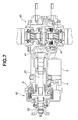
- Fig. 7 shows an example in which the electronic controlled coupling 50 is provided between the propeller shaft and the rear differential 40, as in the first embodiment.
- the internal structure of the electronic controlled coupling 50 is basically similar to the structure of the transfer described above with the exception that the structure around the output shaft and the position of the opening of the cooling oil passage 51 slightly differ from those of the transfer.
- the ECU 7 controls the electronic controlled coupling 50 as in the first embodiment.
- the electronic controlled coupling 50 according to the second embodiment has an operation and beneficial effects similar to those of the electronic controlled coupling 1 according to the first embodiment. Furthermore, in the electronic controlled coupling 50 according to the second embodiment, the wet-type multiple disc clutch 2 is forcibly cooled through the cooling oil passage 51. Thus, the wet-type multiple disc clutch 2 is effectively cooled. Accordingly, the heat resistance of the clutch is further improved.
- the electronic controlled coupling 1 that includes a hydraulic wet-type multiple disc clutch within a complete coupling mechanism increases the durability as a coupling. Also, the electronic controlled coupling 1 has a compact and simple structure and enhances the flexibility in designing.
Landscapes
- Engineering & Computer Science (AREA)
- General Engineering & Computer Science (AREA)
- Physics & Mathematics (AREA)
- Mechanical Engineering (AREA)
- Fluid Mechanics (AREA)
- Electromagnetism (AREA)
- Arrangement And Driving Of Transmission Devices (AREA)
- Hydraulic Clutches, Magnetic Clutches, Fluid Clutches, And Fluid Joints (AREA)
Abstract
Description
- The present invention relates to electronic controlled couplings for transmitting torque with a wet-type multiple disc clutch engageable by hydraulic pressure.
- A technology is known as a power transmission system used for four-wheel drive vehicles in which a coupling mechanism, such as a multiple disc clutch or a viscous coupling, continuously controls a driving force to be distributed to the rear wheels. In particular, four-wheel drive vehicles equipped with an automatic transmission can utilize a hydraulic power source of the automatic transmission; hence, many four-wheel drive vehicles of this type use a hydraulic wet-type multiple disc clutch.
- In contrast, vehicles equipped with a manual transmission do not have their own hydraulic power source; hence, the vehicles may use a coupling that engages a multiple disc clutch by a mechanical driving force. Such a coupling is disclosed, for example, in JP-A-2000-346102. In the coupling of this type, an armature of an electromagnet causes a control clutch, which is a metal multiple disc clutch, to be pressed and engaged, and engaging torque of the control clutch is transmitted to a main clutch, which is a wet-type multiple disc clutch, by a cam mechanism.
- In the known coupling described above, the control clutch is operated by electrical signals and a pressure load of the wet-type multiple disc clutch is amplified by a mechanical cam mechanism. This causes problems of heat resistance and wear resistance of the clutch and the controllability of the clutch due to a change in the temperature of a coil.
- If a hydraulic wet-type multiple disc clutch is used, hydraulic lubrication and cooling considerably solve the above problems. Since, however, a hydraulic power source is needed, the hydraulic wet-type multiple disc clutch of this type is applicable to limited cases. Moreover, a hydraulic circuit, various pressure-regulating valves, and the like are needed for obtaining a clutch operating pressure, thus causing restricted flexibility in designing.
- Accordingly, it is an object of the present invention to increase the durability of an electronic controlled coupling that includes a hydraulic wet-type multiple disc clutch within a complete coupling mechanism and that has a compact and simple structure and enhances the flexibility in designing.
- In accordance with an electronic controlled coupling of the present invention, an oil pump driven by an electric motor is mounted to a case that accommodates a wet-type multiple disc clutch and contains oil. The outlet of the oil pump is connected to a hydraulic chamber of the wet-type multiple disc clutch, with a supply passage for supplying hydraulic pressure therebetween. The supply passage is a one-way closed circuit not having a return path from the hydraulic chamber. Thus, the discharge pressure of the oil pump directly affects the hydraulic chamber of the wet-type multiple disc clutch. The speed of rotation of the electric motor is controlled so that the discharge pressure of the oil pump is equal to an operating pressure required for engagement of the multiple disc clutch.
- Other features and advantages of the present invention will become fully apparent from the following detailed descriptions.
- Figs. 1 to 4 show an electronic controlled coupling according to a first embodiment of the present invention.
- Fig. 1 is a schematic illustration of the structure of an electronic controlled coupling according to the first embodiment;
- Fig. 2 is a sectional view of a main portion of a transfer in a transmission and the electronic controlled coupling according to the first embodiment;
- Fig. 3 is a sectional view of a main portion of a rear differential and the electronic controlled coupling according to the first embodiment;
- Fig. 4 is a flowchart of a process of controlling the electronic controlled coupling;
- Figs. 5 to 7 show an electronic controlled coupling according to a second embodiment of the present invention.
- Fig. 5 is a schematic illustration of the structure of the electronic controlled coupling according to the second embodiment;
- Fig. 6 is a sectional view of a main portion of a transfer in a transmission and the electronic controlled coupling according to the second embodiment; and
- Fig. 7 is a sectional view of a main portion of a rear differential and the electronic controlled coupling according to the second embodiment.
-
- Fig. 1 schematically illustrates the structure of an electronic controlled
coupling 1 provided in a power transmission system used for a vehicle. The electronic controlledcoupling 1 includes a wet-typemultiple disc clutch 2, acoupling case 3, anoil pump 4, an electric motor 5 (hereinafter, referred to as a motor 5), amotor driver 6, and an electric control unit 7 (hereinafter, referred to as an ECU 7), and these are integrated together. The wet-typemultiple disc clutch 2 transmits driving torque by contacting surfaces of a plurality of alternately deposited driving plates and driven plates. Thecoupling case 3 accommodates the wet-typemultiple disc clutch 2 and contains oil therein. Theoil pump 4 is mounted to thecoupling case 3, and sucks and pressurizes the oil to directly supply it to the wet-typemultiple disc clutch 2. Themotor 5 drives theoil pump 4, themotor driver 6 drives themotor 5, and the ECU 7 controls themotor driver 6. Thecoupling case 3 contains the oil for an operating hydraulic pressure and lubrication for the wet-typemultiple disc clutch 2. - The outlet of the
oil pump 4 is connected to ahydraulic chamber 2a, with asupply passage 8 for supplying hydraulic pressure therebetween. Thehydraulic chamber 2a is provided for engaging the wet-typemultiple disc clutch 2. Driving theoil pump 4 by rotation of themotor 5 causes the oil in thecoupling case 3 to be sucked and pressurized. Thus, the discharge pressure of theoil pump 4 directly affects thehydraulic chamber 2a of the wet-typemultiple disc clutch 2. - The
supply passage 8, guiding the oil discharged from theoil pump 4 to the wet-typemultiple disc clutch 2, is a one-way closed circuit not having a return path from thehydraulic chamber 2a. The engagement of the wet-typemultiple disc clutch 2 is controlled by only adjusting the discharge pressure of theoil pump 4 under the control of the speed of rotation of themotor 5. Thus, a pilot circuit, a return circuit, and various regulating valves, such as a pressure-regulating valve and a relief valve, for pressure regulation are not needed. - The ECU 7 controls the rotation of the
motor 5 through themotor driver 6. The ECU 7 determines a running condition on the basis of signals from various sensors (not shown), such as a wheel speed sensor and an acceleration sensor, in order to determine transmission torque suitable for the resulting running condition. Then, theECU 7 controls the speed of rotation of themotor 5 so that the discharge pressure of theoil pump 4 is equal to an operating pressure of the wet-typemultiple disc clutch 2 required for generating the transmission torque. - When the wet-type
multiple disc clutch 2 is disengaged, themotor 5 is controlled to be in a standby mode with a rotation speed set in advance so that the discharge pressure of theoil pump 4 is less than an operating pressure for clutch engagement, for ensuring startup response. In order to engage the wet-typemultiple disc clutch 2, theECU 7 increases the rotation speed of themotor 5 to a rotation speed that corresponds to a pump discharge pressure for generating required transmission torque. - Since the oil discharged from the
oil pump 4 flows to a dead end at thehydraulic chamber 2a of the wet-typemultiple disc clutch 2, relatively high loads may be applied to theoil pump 4 and themotor 5. If, for example, a gear pump is used as theoil pump 4, setting a relatively larger side clearance in advance reduces the pump load. Also, it is desirable that a brushless motor may be used as themotor 5 for durability. Moreover, use of a motor that is available under oil allows an enhanced flexibility in designing and a more compact structure. - The transition from an engaged state to a disengaged state of the wet-type
multiple disc clutch 2 requires some period of time for a reduction in the discharge pressure of theoil pump 4, resulting in possibility of a response delay in disengagement of the wet-typemultiple disc clutch 2. In order to overcome this, it is desirable that arelease passage 9 may be provided in the middle of thesupply passage 8 and that an on-offvalve 10 which is opened and closed by an electromagnetic solenoid or the like may be provided in the middle of therelease passage 9, as indicated by the dotted lines in Fig. 1. When the wet-typemultiple disc clutch 2 is disengaged, opening the on-offvalve 10 in accordance with an instruction from theECU 7 allows an improved release performance. Alternatively, reverse rotation of themotor 5 suppresses the response delay, thus drastically improving the release performance. - Fig. 2 shows an example in which the electronic controlled
coupling 1 described above is applied for a four-wheel drive vehicle equipped with a manual transmission 20 (hereinafter, referred to as a transmission 20). The electronic controlledcoupling 1 is provided, as a transfer, at the rear of thetransmission 20. - In the
transmission 20, asynchromesh mechanism 23 allows transmission gears idling on amain shaft 21 connected to an output shaft of an engine through a clutch (not shown) to be engaged with transmission gears on adrive pinion shaft 22 in accordance with gear change operation. - The driving force of the engine transmitted to the
main shaft 21 is transmitted to the front wheels from a front differential (not shown) via thedrive pinion shaft 22. The driving force is also transmitted to a transfer drivengear 25 via atransfer driving gear 24 coupled to the rear end of thedrive pinion shaft 22. The transfer drivengear 25 is connected to aclutch shaft 26, which is an input shaft of the electronic controlledcoupling 1, and a rearwheel output shaft 27, which is an output shaft of the electronic controlledcoupling 1, is connected to a rear differential (not shown) with apropeller shaft 28 therebetween. Accordingly, the driving force is distributed to the rear wheels. - Oil for operating and lubricating the wet-type
multiple disc clutch 2 is contained in thecoupling case 3 functioning as a transfer case. The wet-typemultiple disc clutch 2 in thecoupling case 3 includes aclutch drum 30 extending from theclutch shaft 26 and having a larger diameter than that of theclutch shaft 26, aclutch hub 31 coupled to a circumference of the rearwheel output shaft 27, aclutch plate unit 32 which is optionally engaged or disengaged between theclutch drum 30 and theclutch hub 31, and apiston 34 pressing theclutch plate unit 32 with apressing member 33. Thehydraulic chamber 2a is provided behind thepiston 34. Thehydraulic chamber 2a allows the wet-typemultiple disc clutch 2 to be engaged by moving thepiston 34 in the axial direction to transmit pressing force to the pressingmember 33. - A
bearing 35 is disposed between the pressingmember 33 and thepiston 34. The bearing 35 transmits pressing force to the rotating pressingmember 33 by linear movement of thepiston 34. Areturn spring 36 urges theclutch plate unit 32 in the disengaging direction against the pressing force of thepiston 34. - An integrated pump unit of the
oil pump 4 and themotor 5 is attached to aside wall unit 3a provided below the rearwheel output shaft 27 of thecoupling case 3. Asuction passage 37 for sucking oil and thesupply passage 8 are arranged within theside wall unit 3a. Thesuction passage 37 is connected to the inlet of theoil pump 4 and is opened to thecoupling case 3. Thesupply passage 8 directly connects an outlet of theoil pump 4 to thehydraulic chamber 2a of the wet-typemultiple disc clutch 2. - The
transmission 20 and the electronic controlledcoupling 1, functioning as a transfer, are separated from each other by anoil seal 38 arranged on the circumference of theclutch shaft 26. Thus, the oil in thetransmission 20 is separated from the oil in the electronic controlledcoupling 1. The same type of oil can be used in thetransmission 20 and the electronic controlledcoupling 1. Alternately, the oil used in the electronic controlledcoupling 1 may be different from the oil used in thetransmission 20. Oil used in the electronic controlledcoupling 1 may be selected in consideration of the characteristics of the wet-typemultiple disc clutch 2 and theoil pump 4. - In the electronic controlled
coupling 1, functioning as a transfer, as described above, the rotation of themotor 5 is controlled by theECU 7 so that transmission toque is generated on the basis of a running condition of a vehicle, a condition of a road surface, and the like. Thus, the torque distribution ratio of front wheels to rear wheels is variable between 100: 0 (clutch is disengaged) and 50: 50 (clutch is engaged). - Variably controlling the transmission torque by controlling the speed of rotation of the
motor 5 pressurizes and transfers the oil discharged from theoil pump 4 directly to thehydraulic chamber 2a of the wet-typemultiple disc clutch 2 so that the discharge pressure of theoil pump 4 is equal to a clutch operating pressure. Thus, controllability of the wet-typemultiple disc clutch 2 can be improved without being affected by various hydraulic circuits, pressure-regulating valves, and the like for obtaining a clutch operating pressure. Moreover, oil contained in thecoupling case 3 lubricates and cools each portion, thus improving the durability of the electronic controlledcoupling 1. - Fig. 3 shows an example in which the electronic controlled
coupling 1 is provided between the propeller shaft and arear differential 40. Referring to Fig. 3, thecoupling case 3 of the electronic controlledcoupling 1 extends backwards to function as part of a case for therear differential 40. Theclutch shaft 26, which is an input shaft of the electronic controlledcoupling 1, is connected to the rear end of the propeller shaft, and the rearwheel output shaft 27, which is an output shaft of the electronic controlledcoupling 1, is connected to the rear differential 40 accommodating aviscous coupling 42, with abevel gear 41 therebetween. The internal structure of the electronic controlledcoupling 1 is basically similar to the structure of the transfer described above with the exception that the structure around the output shaft slightly differs. - A process of a program executed by the
ECU 7 controlling the electronic controlledcoupling 1 will now be described with reference to a flowchart shown in Fig. 4. - In step S101, it is determined whether or not an ignition switch (not shown) is turned on. Step S101 is provided for setting the electronic controlled
coupling 1 to a standby mode prior to running of a vehicle. It may be determined that the electronic controlledcoupling 1 is prepared for a standby mode, for example, by an "on" signal indicating that a vehicle door is opened, instead of by an "ignition-on" signal. - When it is determined that the switch is off in step S101, motor indicating torque, which is indication torque for the
motor 5, is set to zero in step S102. Thus, the electronic controlledcoupling 1 is set to a non-operating state (clutch is disengaged). When it is determined that the switch is on in step S101, the process proceeds to step S103 to run themotor 5 in a standby mode with a rotation speed set in advance. - In step S104, it is determined whether or not front or rear wheel slip is caused on the basis of signals from the wheel speed sensor for the front and rear wheels. When slip is not caused, it is determined whether or not the vehicle is in a starting mode in step S105. When it is determined that the vehicle is in the starting mode, starting control is performed in step S106. In the starting control, for example, the indication torque for the
motor 5 is determined in accordance with the degree of engine throttle opening. For slow starting, the discharge pressure of theoil pump 4 is increased relatively moderately so that the clutch engaging pressure is gradually increased. For quick starting, the discharge pressure of theoil pump 4 is rapidly increased so that the clutch is quickly engaged. - When it is determined that the vehicle is not in the starting mode in step S105, the process proceeds to step S107 to determine whether or not normal control is required. When it is determined that the normal control is not required, the process returns to step S103. When it is determined that the normal control is required, the process proceeds to step S108 to perform the normal control. In the normal control, for example, the indication torque for the
motor 5 is determined on the basis of the degree of throttle opening and the speed of the vehicle, and the discharge pressure of theoil pump 4 is controlled to a clutch operating pressure for generating transmission torque suitable for the running state. - When it is determined that the front or rear wheel slip is caused in step S104, the process proceeds to step S109 to perform the slip control. In the slip control, for example, when front wheel slip is caused, the indication torque for the
motor 5 is increased in accordance with the degree of the slip in order to adjust the discharge pressure of theoil pump 4, that is, the clutch engaging pressure, thus suppressing the front wheel slip. - Accordingly, the electronic controlled
coupling 1 according to the embodiment includes the integrated wet-typemultiple disc clutch 2, theoil pump 4, and themotor 5. Theoil pump 4 is driven by themotor 5, and the discharge pressure of theoil pump 4 is adjusted by controlling the rotation speed of themotor 5. The clutch engaging pressure is controlled through the resulting discharge pressure of theoil pump 4. The electronic controlledcoupling 1 has a compact structure and is mechanically complete as a coupling, thus enhancing flexibility in designing. Therefore, the electronic controlledcoupling 1 is readily applicable to power transmission systems used for vehicles. Particularly, the electronic controlledcoupling 1 is effectively used for manual transmission-equipped vehicles without their own hydraulic power source. - In the electronic controlled
coupling 1 according to the embodiment, hydraulic lubrication is readily performed and heat resistance of the clutch is improved. Moreover, the clutch operating pressure can be controlled by the control of the rotation speed of themotor 5. Thus, a hydraulic circuit and various regulating valves for obtaining the clutch operating pressure are not needed, thus reducing the cost. - An electronic controlled coupling according to a second embodiment of the present invention will now be described. Similar components as in the first embodiment are referred to with the same reference numerals, and the descriptions of those similar components will not be repeated here.
- Referring to Fig. 5, an electronic controlled
coupling 50 includes a coolingoil passage 51 for supplying cooling oil in order to effectively cool the wet-typemultiple disc clutch 2. The coolingoil passage 51 branches off from the midstream of thesupply passage 8 for supplying hydraulic pressure. Accordingly, the wet-typemultiple disc clutch 2 is forcibly cooled by the oil from the coolingoil passage 51. The coolingoil passage 51 has anorifice 52 in the middle thereof, so that the amount of the oil for forcibly cooling the wet-typemultiple disc clutch 2 is limited to the minimum necessary. Theorifice 52 is not necessarily provided. If the minimum amount of the cooling oil required for cooling the wet-typemultiple disc clutch 2 can be ensured without influencing the clutch operation, theorifice 52 may be omitted. - Fig. 6 shows an example in which the electronic controlled
coupling 50 according to the second embodiment is applied for a four-wheel drive vehicle equipped with themanual transmission 20, as in the first embodiment. The electronic controlledcoupling 50 is provided, as a transfer, at the rear of thetransmission 20. The coolingoil passage 51 branches off from thesupply passage 8 that connects the outlet of theoil pump 4 to thehydraulic chamber 2a of the wet-typemultiple disc clutch 2. The coolingoil passage 51 is opened to a space around the circumference of the rearwheel output shaft 27 in thecoupling case 3. Theorifice 52 is provided in the coolingoil passage 51. - Fig. 7 shows an example in which the electronic controlled
coupling 50 is provided between the propeller shaft and the rear differential 40, as in the first embodiment. The internal structure of the electronic controlledcoupling 50 is basically similar to the structure of the transfer described above with the exception that the structure around the output shaft and the position of the opening of the coolingoil passage 51 slightly differ from those of the transfer. - The
ECU 7 controls the electronic controlledcoupling 50 as in the first embodiment. - The electronic controlled
coupling 50 according to the second embodiment has an operation and beneficial effects similar to those of the electronic controlledcoupling 1 according to the first embodiment. Furthermore, in the electronic controlledcoupling 50 according to the second embodiment, the wet-typemultiple disc clutch 2 is forcibly cooled through the coolingoil passage 51. Thus, the wet-typemultiple disc clutch 2 is effectively cooled. Accordingly, the heat resistance of the clutch is further improved. - As described above, the electronic controlled
coupling 1 according to the present invention that includes a hydraulic wet-type multiple disc clutch within a complete coupling mechanism increases the durability as a coupling. Also, the electronic controlledcoupling 1 has a compact and simple structure and enhances the flexibility in designing. - In the present invention, it is obvious that widely different embodiments may be made without departing from the spirit and scope of the present invention. The present invention is not limited to the specific embodiments as described thereof.
Claims (4)
- An electronic controlled coupling (1) for transmitting torque with a wet-type multiple disc clutch (2) that is engageable by hydraulic pressure, characterized in that:oil contained in a case (3) that accommodates the wet-type multiple disc clutch (2) and supplied to a hydraulic chamber (2a) for engagement of the wet-type multiple disc clutch (2);an oil pump (4) connected to the case (3) and driven by an electric motor (5) to pressurize and supply the oil to the hydraulic chamber (2a);a supply passage (8) for supplying hydraulic pressure connected an outlet of the oil pump (4) to the hydraulic chamber (2a) so that the discharge pressure of the oil pump (4) directly affects the hydraulic chamber (2a), the supply passage (8) is a one-way closed circuit not having a return path from the hydraulic chamber (2a); andcontrol means for controlling the speed of rotation of the electric motor (5) so that the discharge pressure of the oil pump (4) is equal to an operating pressure required for the wet-type multiple disc clutch (2).
- The electronic controlled coupling (1) according to Claim 1, characterized in that:a release passage (9) is provided in the middle of the supply passage (8); andan on-off valve (10) that is opened when the wet-type multiple disc clutch (2) is disengaged is provided in the release passage (9).
- An electronic controlled coupling (50) for transmitting torque with a wet-type multiple disc clutch (2) that is engageable by hydraulic pressure, the electronic controlled coupling (50) being characterized in that:oil contained in a case (3) that accommodates the wet-type multiple disc clutch (2) and supplied to a hydraulic chamber (2a) for engagement of the wet-type multiple disc clutch (2);an oil pump (4) connected to the case (3) and driven by an electric motor (5) to pressurize and supply the oil to the hydraulic chamber (2a);a supply passage (8) for supplying hydraulic pressure connected an outlet of the oil pump (4) to the hydraulic chamber (2a) so that the discharge pressure of the oil pump (4) directly affects the hydraulic chamber (2a), the supply passage (8) is a one-way closed circuit not having a return path from the hydraulic chamber (2a);a cooling oil passage (51) for supplying cooling oil in order to cool the wet-type multiple disc clutch (2), the cooling oil passage (51) branching off from the supply passage (8); andcontrol means for controlling the speed of rotation of the electric motor (5) so that the discharge pressure of the oil pump (4) is equal to an operating pressure required for the wet-type multiple disc clutch (2).
- An electronic controlled coupling (50) according to Claim 3, characterized in that an orifice (52) is provided in the cooling oil passage (51).
Applications Claiming Priority (4)
| Application Number | Priority Date | Filing Date | Title |
|---|---|---|---|
| JP2002174812 | 2002-06-14 | ||
| JP2002174811 | 2002-06-14 | ||
| JP2002174812A JP2004019769A (en) | 2002-06-14 | 2002-06-14 | Electronically controlled coupling |
| JP2002174811A JP2004019768A (en) | 2002-06-14 | 2002-06-14 | Electronically controlled coupling |
Publications (2)
| Publication Number | Publication Date |
|---|---|
| EP1371868A1 true EP1371868A1 (en) | 2003-12-17 |
| EP1371868B1 EP1371868B1 (en) | 2005-10-05 |
Family
ID=29586062
Family Applications (1)
| Application Number | Title | Priority Date | Filing Date |
|---|---|---|---|
| EP03012273A Revoked EP1371868B1 (en) | 2002-06-14 | 2003-06-11 | Electronic controlled coupling |
Country Status (3)
| Country | Link |
|---|---|
| US (1) | US6848555B2 (en) |
| EP (1) | EP1371868B1 (en) |
| DE (1) | DE60301762T2 (en) |
Cited By (9)
| Publication number | Priority date | Publication date | Assignee | Title |
|---|---|---|---|---|
| WO2005038281A1 (en) * | 2003-10-13 | 2005-04-28 | Gkn Driveline International Gmbh | Axial displacement mechanism |
| DE102005014654A1 (en) * | 2005-03-31 | 2006-10-05 | Gkn Driveline International Gmbh | Motor vehicle hydraulic pump |
| EP2020522A1 (en) * | 2007-08-02 | 2009-02-04 | HONDA MOTOR CO., Ltd. | Hydraulic vehicle clutch system and method |
| GB2466002A (en) * | 2008-12-05 | 2010-06-09 | Gm Global Tech Operations Inc | Clutch hydraulic system with a pump controlled as a function of clutch torque |
| EP2196692A1 (en) * | 2007-03-27 | 2010-06-16 | Univance Corporation | Driving force transmitting device |
| US7958983B2 (en) | 2005-12-13 | 2011-06-14 | Zf Friedrichshafen Ag | Hydraulic system in motor vehicles |
| ITTO20111018A1 (en) * | 2011-11-05 | 2012-02-04 | Torino Politecnico | ELECTROHYDROSTATIC SYSTEM FOR ASSISTED IMPLEMENTATION OF A CLUTCH. |
| CN102729815A (en) * | 2011-04-13 | 2012-10-17 | 本田技研工业株式会社 | Oil pressure supply device of driving force distribution device |
| US8900086B2 (en) | 2007-08-02 | 2014-12-02 | Honda Motor Co., Ltd. | Hydraulic vehicle clutch system, drivetrain for a vehicle including same, and method |
Families Citing this family (22)
| Publication number | Priority date | Publication date | Assignee | Title |
|---|---|---|---|---|
| US8083041B2 (en) * | 2005-08-11 | 2011-12-27 | American Axle & Manufacturing, Inc. | Electrohydraulic torque transfer device |
| US8197386B2 (en) | 2005-08-11 | 2012-06-12 | American Axle & Manufacturing, Inc. | Electrohydraulic torque transfer device and temperature control system |
| US7743899B2 (en) * | 2005-08-11 | 2010-06-29 | American Axle & Manufacturing, Inc. | Electrohydraulic torque transfer device and control system |
| US7445106B2 (en) * | 2005-08-11 | 2008-11-04 | American Axle & Manufacturing, Inc. | Electronically-controlled hydraulically-actuated coupling |
| DE102005053555B3 (en) * | 2005-11-08 | 2007-08-02 | Gkn Driveline International Gmbh | Ball ramp arrangement with variable pitch of the ball grooves |
| US7896146B2 (en) * | 2006-12-20 | 2011-03-01 | Borgwarner, Inc. | Clutch device utilizing brushless motor |
| US20090032352A1 (en) * | 2007-08-02 | 2009-02-05 | Borgwarner Inc. | Motor actuated range shift and on demand 4wd |
| US20090032360A1 (en) * | 2007-08-02 | 2009-02-05 | Tetsushi Asano | Hydraulic Vehicle Clutch System and Method |
| US8052578B2 (en) * | 2008-05-30 | 2011-11-08 | Honda Motor Co., Ltd. | Hydraulic vehicle clutch system and preemptive control method |
| US8527160B2 (en) * | 2010-02-05 | 2013-09-03 | Honda Motor Co., Ltd. | Control system and method for automatic selection of a low range gear ratio for a vehicle drivetrain |
| US8449430B2 (en) * | 2010-02-05 | 2013-05-28 | Honda Motor Co., Ltd. | Transversely mounted transaxle having a low range gear assembly and powertrain for a vehicle including same |
| DE102010021000A1 (en) | 2010-05-12 | 2011-11-17 | Getrag Getriebe- Und Zahnradfabrik Hermann Hagenmeyer Gmbh & Cie Kg | Method for controlling a friction clutch |
| US8364369B2 (en) | 2010-07-30 | 2013-01-29 | Honda Motor Co., Ltd. | Low range drive ratio transfer changeover anti-rollback system and method |
| US8452504B2 (en) | 2010-07-30 | 2013-05-28 | Honda Motor Co., Ltd. | Control system and method for automatic control of selection of on-demand all-wheel drive assembly for a vehicle drivetrain |
| US8534409B2 (en) | 2010-07-30 | 2013-09-17 | Honda Motor Co., Ltd. | Drivetrain for a vehicle and method of controlling same |
| DE102011102277B4 (en) | 2011-05-23 | 2017-03-23 | Getrag Getriebe- Und Zahnradfabrik Hermann Hagenmeyer Gmbh & Cie Kg | Powertrain for a motor vehicle |
| EP2722563A4 (en) * | 2011-06-14 | 2016-08-03 | Jatco Ltd | Coast stop vehicle |
| DE102011117488B4 (en) * | 2011-10-26 | 2013-05-23 | Getrag Getriebe- Und Zahnradfabrik Hermann Hagenmeyer Gmbh & Cie Kg | Motor vehicle drive train and hydraulic circuit therefor with a variable speed pump |
| SE536992C2 (en) * | 2013-02-28 | 2014-11-25 | Borgwarner Torqtransfer Systems Ab | Hydraulic disc coupling for an AWD vehicle with a shut-off valve |
| US9016150B2 (en) * | 2013-07-29 | 2015-04-28 | Ford Global Technologies, Llc | Transmission having selectable power transfer shaft |
| GB2558214B (en) | 2016-12-22 | 2021-07-21 | Concentric Birmingham Ltd | Auxiliary drive system for a pump |
| GB2602504B (en) | 2021-01-05 | 2023-03-01 | Concentric Birmingham Ltd | Hybrid pump apparatus |
Citations (4)
| Publication number | Priority date | Publication date | Assignee | Title |
|---|---|---|---|---|
| JPS5891927A (en) * | 1981-11-27 | 1983-06-01 | Ebara Corp | Power transmission device |
| JPH09112592A (en) * | 1995-10-17 | 1997-05-02 | Unisia Jecs Corp | Automatic clutch |
| JP2000346102A (en) | 1999-06-02 | 2000-12-12 | Tochigi Fuji Ind Co Ltd | Coupling |
| AT5220U1 (en) * | 2001-04-02 | 2002-04-25 | Steyr Powertrain Ag & Co Kg | SPEED DIFFERENTIAL-RELATED HYDRAULIC CLUTCH WITH CONTROL VALVE |
Family Cites Families (7)
| Publication number | Priority date | Publication date | Assignee | Title |
|---|---|---|---|---|
| FR1557888A (en) * | 1968-01-05 | 1969-02-21 | ||
| FR2633072B1 (en) * | 1988-06-21 | 1990-11-02 | Renault | CONTROL, REGULATION AND CONTROL CIRCUIT FOR A FLUID FLOW |
| US4984663A (en) * | 1989-03-07 | 1991-01-15 | Fuji Tekko Co., Ltd. | Transfer apparatus for 4-wheel driving |
| JP3791625B2 (en) * | 1995-08-11 | 2006-06-28 | 日産自動車株式会社 | Four-wheel drive control device for vehicle |
| JPH09151963A (en) * | 1995-12-01 | 1997-06-10 | Nsk Warner Kk | Hydraulic circuit for starting clutch |
| JPH11311315A (en) * | 1998-04-24 | 1999-11-09 | Hitachi Ltd | Control device for automatic transmission |
| JP2002187446A (en) * | 2000-12-21 | 2002-07-02 | Fuji Heavy Ind Ltd | Power distribution device for four-wheel drive vehicles |
-
2003
- 2003-06-11 DE DE60301762T patent/DE60301762T2/en not_active Revoked
- 2003-06-11 EP EP03012273A patent/EP1371868B1/en not_active Revoked
- 2003-06-12 US US10/459,600 patent/US6848555B2/en not_active Expired - Fee Related
Patent Citations (4)
| Publication number | Priority date | Publication date | Assignee | Title |
|---|---|---|---|---|
| JPS5891927A (en) * | 1981-11-27 | 1983-06-01 | Ebara Corp | Power transmission device |
| JPH09112592A (en) * | 1995-10-17 | 1997-05-02 | Unisia Jecs Corp | Automatic clutch |
| JP2000346102A (en) | 1999-06-02 | 2000-12-12 | Tochigi Fuji Ind Co Ltd | Coupling |
| AT5220U1 (en) * | 2001-04-02 | 2002-04-25 | Steyr Powertrain Ag & Co Kg | SPEED DIFFERENTIAL-RELATED HYDRAULIC CLUTCH WITH CONTROL VALVE |
Non-Patent Citations (2)
| Title |
|---|
| PATENT ABSTRACTS OF JAPAN vol. 007, no. 189 (M - 237) 18 August 1983 (1983-08-18) * |
| PATENT ABSTRACTS OF JAPAN vol. 1997, no. 09 30 September 1997 (1997-09-30) * |
Cited By (15)
| Publication number | Priority date | Publication date | Assignee | Title |
|---|---|---|---|---|
| DE10349030A1 (en) * | 2003-10-13 | 2005-05-12 | Gkn Driveline Int Gmbh | axial setting |
| DE10349030B4 (en) * | 2003-10-13 | 2005-10-20 | Gkn Driveline Int Gmbh | axial setting |
| WO2005038281A1 (en) * | 2003-10-13 | 2005-04-28 | Gkn Driveline International Gmbh | Axial displacement mechanism |
| US7946402B2 (en) | 2005-03-31 | 2011-05-24 | Gkn Driveline International Gmbh | Motor vehicle hydraulic pump |
| DE102005014654A1 (en) * | 2005-03-31 | 2006-10-05 | Gkn Driveline International Gmbh | Motor vehicle hydraulic pump |
| DE102005014654B4 (en) * | 2005-03-31 | 2014-03-06 | Gkn Driveline International Gmbh | Motor vehicle hydraulic pump |
| US7958983B2 (en) | 2005-12-13 | 2011-06-14 | Zf Friedrichshafen Ag | Hydraulic system in motor vehicles |
| EP2196692A1 (en) * | 2007-03-27 | 2010-06-16 | Univance Corporation | Driving force transmitting device |
| US8256593B2 (en) | 2007-03-27 | 2012-09-04 | Univance Corporation | Driving force transmitting device |
| EP2020522A1 (en) * | 2007-08-02 | 2009-02-04 | HONDA MOTOR CO., Ltd. | Hydraulic vehicle clutch system and method |
| US8900086B2 (en) | 2007-08-02 | 2014-12-02 | Honda Motor Co., Ltd. | Hydraulic vehicle clutch system, drivetrain for a vehicle including same, and method |
| US9611906B2 (en) | 2007-08-02 | 2017-04-04 | Honda Motor Co., Ltd. | Hydraulic vehicle clutch system and method |
| GB2466002A (en) * | 2008-12-05 | 2010-06-09 | Gm Global Tech Operations Inc | Clutch hydraulic system with a pump controlled as a function of clutch torque |
| CN102729815A (en) * | 2011-04-13 | 2012-10-17 | 本田技研工业株式会社 | Oil pressure supply device of driving force distribution device |
| ITTO20111018A1 (en) * | 2011-11-05 | 2012-02-04 | Torino Politecnico | ELECTROHYDROSTATIC SYSTEM FOR ASSISTED IMPLEMENTATION OF A CLUTCH. |
Also Published As
| Publication number | Publication date |
|---|---|
| EP1371868B1 (en) | 2005-10-05 |
| DE60301762T2 (en) | 2006-05-18 |
| DE60301762D1 (en) | 2006-02-16 |
| US6848555B2 (en) | 2005-02-01 |
| US20030230461A1 (en) | 2003-12-18 |
Similar Documents
| Publication | Publication Date | Title |
|---|---|---|
| US6848555B2 (en) | Electronic controlled coupling | |
| US7175013B2 (en) | On-demand cooling control for power transfer system | |
| US7021445B2 (en) | Low power hydraulic clutch actuation systems | |
| US7059462B2 (en) | Hydraulic clutch actuation system | |
| US7007782B2 (en) | Control of a hydraulic coupling system | |
| US7128688B2 (en) | Hydraulic control for automatic transmission | |
| JP5445045B2 (en) | Hydraulic control device for automatic transmission | |
| US8413437B2 (en) | Transmission hydraulic control system having independently controlled stator cooling flow | |
| US20100274456A1 (en) | Driving-force transmitting apparatus for four-wheel-drive vehicle | |
| US8052578B2 (en) | Hydraulic vehicle clutch system and preemptive control method | |
| US8632439B2 (en) | Control device for vehicular lockup clutch | |
| WO2008033180A1 (en) | Coupling assembly | |
| US7210566B2 (en) | Friction coupling assembly with auxiliary clutch control of fluid pump | |
| US20090032359A1 (en) | Hydraulic Vehicle Clutch System and Method | |
| US20220268341A1 (en) | Module for a system for synchronizing and driving a transmission gearbox countershaft | |
| US10808735B2 (en) | Transmission park valve with steel saddle | |
| US20080296124A1 (en) | Hydraulic System in Motor Vehicles | |
| JP2004019768A (en) | Electronically controlled coupling | |
| US7399257B2 (en) | System and method of controlling automatic transmission | |
| EP1760348A2 (en) | Driving force transmitting apparatus | |
| US4696383A (en) | Hydraulic clutch for motor vehicles, having creep-inhibiting feature | |
| JP2004019769A (en) | Electronically controlled coupling | |
| JP7444124B2 (en) | Vehicle drive system | |
| JP4696398B2 (en) | Direct transmission clutch control device for automatic transmission | |
| JPH0751980B2 (en) | Hydraulic control device for continuously variable transmission |
Legal Events
| Date | Code | Title | Description |
|---|---|---|---|
| PUAI | Public reference made under article 153(3) epc to a published international application that has entered the european phase |
Free format text: ORIGINAL CODE: 0009012 |
|
| AK | Designated contracting states |
Kind code of ref document: A1 Designated state(s): AT BE BG CH CY CZ DE DK EE ES FI FR GB GR HU IE IT LI LU MC NL PT RO SE SI SK TR |
|
| AX | Request for extension of the european patent |
Extension state: AL LT LV MK |
|
| 17P | Request for examination filed |
Effective date: 20031023 |
|
| 17Q | First examination report despatched |
Effective date: 20040303 |
|
| AKX | Designation fees paid |
Designated state(s): DE FR GB |
|
| GRAP | Despatch of communication of intention to grant a patent |
Free format text: ORIGINAL CODE: EPIDOSNIGR1 |
|
| GRAS | Grant fee paid |
Free format text: ORIGINAL CODE: EPIDOSNIGR3 |
|
| GRAA | (expected) grant |
Free format text: ORIGINAL CODE: 0009210 |
|
| AK | Designated contracting states |
Kind code of ref document: B1 Designated state(s): DE FR GB |
|
| REG | Reference to a national code |
Ref country code: GB Ref legal event code: FG4D |
|
| REF | Corresponds to: |
Ref document number: 60301762 Country of ref document: DE Date of ref document: 20060216 Kind code of ref document: P |
|
| RAP2 | Party data changed (patent owner data changed or rights of a patent transferred) |
Owner name: JTEKT CORPORATION Owner name: FUJI JUKOGYO KABUSHIKI KAISHA |
|
| PLBI | Opposition filed |
Free format text: ORIGINAL CODE: 0009260 |
|
| PLAX | Notice of opposition and request to file observation + time limit sent |
Free format text: ORIGINAL CODE: EPIDOSNOBS2 |
|
| 26 | Opposition filed |
Opponent name: MAGNA POWERTRAIN AG & CO. KG Effective date: 20060705 |
|
| PG25 | Lapsed in a contracting state [announced via postgrant information from national office to epo] |
Ref country code: FR Free format text: LAPSE BECAUSE OF FAILURE TO SUBMIT A TRANSLATION OF THE DESCRIPTION OR TO PAY THE FEE WITHIN THE PRESCRIBED TIME-LIMIT Effective date: 20061020 |
|
| EN | Fr: translation not filed | ||
| PLBB | Reply of patent proprietor to notice(s) of opposition received |
Free format text: ORIGINAL CODE: EPIDOSNOBS3 |
|
| PGFP | Annual fee paid to national office [announced via postgrant information from national office to epo] |
Ref country code: DE Payment date: 20070607 Year of fee payment: 5 |
|
| GBPC | Gb: european patent ceased through non-payment of renewal fee |
Effective date: 20070611 |
|
| RDAF | Communication despatched that patent is revoked |
Free format text: ORIGINAL CODE: EPIDOSNREV1 |
|
| PG25 | Lapsed in a contracting state [announced via postgrant information from national office to epo] |
Ref country code: GB Free format text: LAPSE BECAUSE OF NON-PAYMENT OF DUE FEES Effective date: 20070611 |
|
| RDAG | Patent revoked |
Free format text: ORIGINAL CODE: 0009271 |
|
| STAA | Information on the status of an ep patent application or granted ep patent |
Free format text: STATUS: PATENT REVOKED |
|
| 27W | Patent revoked |
Effective date: 20080227 |
|
| PG25 | Lapsed in a contracting state [announced via postgrant information from national office to epo] |
Ref country code: FR Free format text: LAPSE BECAUSE OF FAILURE TO SUBMIT A TRANSLATION OF THE DESCRIPTION OR TO PAY THE FEE WITHIN THE PRESCRIBED TIME-LIMIT Effective date: 20051005 |