EP1371816A2 - Assembled Camshaft for Engine and Production Method Thereof - Google Patents
Assembled Camshaft for Engine and Production Method Thereof Download PDFInfo
- Publication number
- EP1371816A2 EP1371816A2 EP03009527A EP03009527A EP1371816A2 EP 1371816 A2 EP1371816 A2 EP 1371816A2 EP 03009527 A EP03009527 A EP 03009527A EP 03009527 A EP03009527 A EP 03009527A EP 1371816 A2 EP1371816 A2 EP 1371816A2
- Authority
- EP
- European Patent Office
- Prior art keywords
- shaft member
- hollow shaft
- assembled camshaft
- cam lobe
- engine according
- Prior art date
- Legal status (The legal status is an assumption and is not a legal conclusion. Google has not performed a legal analysis and makes no representation as to the accuracy of the status listed.)
- Granted
Links
Images




Classifications
-
- F—MECHANICAL ENGINEERING; LIGHTING; HEATING; WEAPONS; BLASTING
- F01—MACHINES OR ENGINES IN GENERAL; ENGINE PLANTS IN GENERAL; STEAM ENGINES
- F01L—CYCLICALLY OPERATING VALVES FOR MACHINES OR ENGINES
- F01L1/00—Valve-gear or valve arrangements, e.g. lift-valve gear
- F01L1/02—Valve drive
- F01L1/022—Chain drive
-
- F—MECHANICAL ENGINEERING; LIGHTING; HEATING; WEAPONS; BLASTING
- F01—MACHINES OR ENGINES IN GENERAL; ENGINE PLANTS IN GENERAL; STEAM ENGINES
- F01L—CYCLICALLY OPERATING VALVES FOR MACHINES OR ENGINES
- F01L1/00—Valve-gear or valve arrangements, e.g. lift-valve gear
- F01L1/02—Valve drive
- F01L1/04—Valve drive by means of cams, camshafts, cam discs, eccentrics or the like
- F01L1/047—Camshafts
-
- F—MECHANICAL ENGINEERING; LIGHTING; HEATING; WEAPONS; BLASTING
- F01—MACHINES OR ENGINES IN GENERAL; ENGINE PLANTS IN GENERAL; STEAM ENGINES
- F01L—CYCLICALLY OPERATING VALVES FOR MACHINES OR ENGINES
- F01L1/00—Valve-gear or valve arrangements, e.g. lift-valve gear
- F01L1/02—Valve drive
- F01L1/024—Belt drive
-
- F—MECHANICAL ENGINEERING; LIGHTING; HEATING; WEAPONS; BLASTING
- F01—MACHINES OR ENGINES IN GENERAL; ENGINE PLANTS IN GENERAL; STEAM ENGINES
- F01L—CYCLICALLY OPERATING VALVES FOR MACHINES OR ENGINES
- F01L2303/00—Manufacturing of components used in valve arrangements
-
- Y—GENERAL TAGGING OF NEW TECHNOLOGICAL DEVELOPMENTS; GENERAL TAGGING OF CROSS-SECTIONAL TECHNOLOGIES SPANNING OVER SEVERAL SECTIONS OF THE IPC; TECHNICAL SUBJECTS COVERED BY FORMER USPC CROSS-REFERENCE ART COLLECTIONS [XRACs] AND DIGESTS
- Y10—TECHNICAL SUBJECTS COVERED BY FORMER USPC
- Y10T—TECHNICAL SUBJECTS COVERED BY FORMER US CLASSIFICATION
- Y10T29/00—Metal working
- Y10T29/49—Method of mechanical manufacture
- Y10T29/49229—Prime mover or fluid pump making
- Y10T29/49293—Camshaft making
Definitions
- the present invention relates to an assembled camshaft for engine and a production method thereof, and more particularly to the assembled camshaft including a cam lobe piece and a hollow shaft member and the production method thereof.
- the structure having the hexagonal nut shaped parts causes an increase in cost due to an increase in number of parts and a loss of a lightening effect. Further, since a size of the hexagon is large, there arises a problem that a degree of a design freedom of an engine, particularly of a cylinder head portion, is lowered.
- the present invention is devised in order to solve the problems of the conventional arts. Therefore, it is an object of the present invention is to provide a light assembled camshaft for engine having good mechanical durability and maintainability, and a production method thereof.
- a assembled camshaft for engine having a cam lobe piece and a hollow shaft member wherein the hollow shaft member has at least two shaft fixing surfaces which are formed by a plasticity process on a portion corresponding to a position between cylinders.
- the shaft fixing surfaces function as rotation brakes of the shaft member at the time of fastening a sprocket.
- a production method of an assembled camshaft for engine having a cam lobe piece and a hollow shaft member including a step of forming by a plasticity processing tool at least two shaft fixing surfaces on a portion of the hollow shaft member corresponding to a position between cylinders.
- a special exclusive working tool is not necessary, and the camshaft can be easily attached/detached by a working tool such as a spanner. Since a distance between the cam lobe pieces is long and a working space can be secured easily, the working tool is easily inserted. Namely, interference between the working tool and the parts hardly occurs, and satisfactory assembly workability can be secured.
- the shaft fixing surface can be arranged easily so that deformation of the hollow shaft member which is caused by the forming of the cam shaft surface, does not influence a fastened portion of the cam lobe member. Therefore, reliability of the fastening force of the cam lobe piece can be secured.
- the light assembled camshaft for engine having the satisfactory mechanical durability and maintainability can be provided.
- the distance between the cam lobe pieces is long, a degree of design freedom of the plasticity processing tool for forming the shaft forming surface is large. Therefore, in this production method, the plasticity processing tool having large rigidity and long life can be used.
- an assembled camshaft for engine 10 has a hollow shaft member 11, a plurality of cam lobe pieces 12 and journals 13.
- the cam lobe piece 12 is, for example, a forging or a sinter, and it is located with a phase difference corresponding to a crank angle and is fitted into the hollow shaft member 11.
- the hollow shaft member 11 has at least two shaft fixing surfaces 11A which are made of, for example, a steel pipe and are formed on a portion corresponding to a position between cylinders (or a position between the cam lobe pieces 12) by plasticity process.
- the shaft fixing surface 11A functions as a rotation brake of the shaft member 11 at the time of fastening the sprocket 14.
- the hollow shaft member 11 Since the hollow shaft member 11 has the shaft fixing surface 11A, it does not require additional parts such as a hexagonal nut shaped part. Therefore, an increase in cost due to an increase in number of parts and a loss of a lightening effect do not occur. Moreover, a special exclusive (sole) working tool (for example, a wrench having a square aperture or an octagon aperture) is not necessary, and the camshaft 10 can be easily attached/detached by a working tool such as a spanner.
- a working tool such as a spanner.
- the shaft fixing surface 11A is formed by the plasticity process, a decrease in its thickness is suppressed, and lightening of the parts is not hindered and securing of mechanical durability is easy.
- a number of the shaft fixing surfaces 11A is not particularly limited as long as it is at least two. In this connection, for example, in the case where they are composed of a pair of parallel surfaces, the forming is easy and thus producibility is excellent.
- a diameter of the portion provided with the shaft fixing surface 11A is smaller than an original diameter of the hollow shaft member 11. In this case, an interference between the tool and the parts difficulty occurs, so that more satisfactory maintainability (assembly workability) can be secured. A degree of design freedom of the engine, particularly a cylinder head portion can be improved.
- the shaft fixing surface 11A is formed on the portion corresponding to the position between the cylinders, a distance between the cam lobe pieces is long. Therefore, since a working space can be easily secured, the working tool can be easily inserted. Namely, the interference between the working tool and the parts hardly occurs, so that the satisfactory assembly workability can be secured.
- the shaft fixing surfaces 11A can be arranged easily so that deformation of the hollow shaft member 11 which is caused by the forming of the shaft fixing surfaces 11A does not influence the fastened portion of the cam lobe pieces 11. Therefore reliability of fastening forces of the cam lobe pieces 11 can be secured.
- the position of the shaft fixing surface 11A is not particularly limited as long as it corresponds to the position between the cylinders. However, in the case where the shaft fixing surface 11A is arranged between the cylinders positioned on a rightmost side far from the sprocket 14 (a vicinity of the other end on an opposite side to one end fastened to the sprocket) , this is particularly preferable from a viewpoint of the assembly workability. Moreover, in order to improve the lightening, when the thickness of the hollow shaft member 11 is thinned, the shaft fixing surface 11A may be arranged on a leftmost side between the cylinders (one end side) so that distortion might not occur on the hollow shaft member 11.
- Fig. 2 is a diagram for explaining a deformation influence range due to the forming of the shaft fixing surfaces 11A.
- the applied hollow shaft member (steel pipe) 11 has an outer diameter of 25.5 mm and a thickness of 3.3 mm. A distance between the cam lobe pieces is 23 mm.
- the influence range of the deformation of the hollow shaft member 11 caused by the forming of the shaft fixing surface 11A is about 6 mm (distance D) . Namely, in the case where the shaft fixing surface 11A is arranged on a portion separated by not less than 6 mm from an end surface of the adjacent cam lobe piece 12, an amount of the deformation E of the hollow shaft member 11 does not influence the fastened portion of the cam lobe piece 12.
- the shaft fixing surface 11A is arranged on a portion separated by not less than 6 mm from the end surface of the adjacent cam lobe piece 12. Moreover, in the case where a size of the shaft fixing surface 11A is increased to be optimized, the workability is further improved.
- the influence range of the deformation of the hollow shaft member 11 show the approximately same effect. Further, also in the case where a material of the hollow shaft member 11 is changed, the influence range shows the approximately same effect. Namely, the influence range of the deformation of the hollow shaft member 11 has small dependency with respect to the material and the distance between the cam lobe pieces 12.
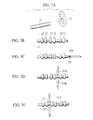
- the production method of the assembled camshaft 10 has, as shown in Figs. 3A through 3E, the inserting step, the mouth expanding fastening step, the surface forming step and the bending correcting step.
- a predetermined number of the cam lobe pieces 12 are inserted into the hollow shaft member 11 so as to be located.
- a mandrel 20 is inserted into a hollow portion of the hollow shaft member 11, and a mouth of the hollow shaft member 11 is expanded and caulked, so that the cam lobe pieces 12 are fastened mechanically to the hollow shaft member 11.
- apertures of the cam lobe pieces 12 through which the hollow shaft member 11 is passed are shaped aspolygon, for example, pentagon, hexagon, octagon. Therefore, after the mouth expanding fastening step, each of the cam lobe pieces 12 is refrained from rotating around the hollow shaft member 11 by concave portions and convex portions due to the polygonal shape of the apertures of the cam lobe pieces 12.
- Figs. 4A and 4B and Fig. 5 show examples of the plasticity processing tools 21A, 21B, 21A-2, 21B-2.
- the hollow shaft member 11 is rotated to a direction of R. Consequently, in a state where the hollow shaft member 11 is kept to be refrained from rotating in the direction of R, the shaft fixing surfaces are formed again by the plasticity processing tools 21A, 21B as shown in Fig. 4B repeatedly, so that the polygonal shaft fixing surfaces 11A are formed.
- the surface forming step does not influence the mouth expanding fastening step because this step is executed after the mouth expanding fastening step.
- bending of the hollow shaft member 11 which occurs in the mouth expanding fastening step and the surface forming step is corrected. Namely, since the step of correcting the bending based on the mouth expanding fastening step and the step of correcting the bending based on the surface forming step are executed simultaneously at one time, an increase in steps is prevented so that a line is shortened and the cost is reduced.
- the bending correcting step shown in Fig. 3E firstly the bending of the hollow shaft member 11 is measured.
- the portion which requires the correction of the bending of the hollow shaft member 11 detected based on the measured result, is plastically deformed by pressurizing the portion to a direction crossing a longitudinal direction of the hollow shaft member 11 using the plasticity processing tool 22.
- a side which is opposite to the side pressurized by the plasticity processing tool is supported by a receiving section 23.
- the hollow shaft member 11 whose bending is corrected proceeds to mechanical processing step(machining, grinding or lapping process) . Therefore, at the mechanical processing step, bias of a machining allowance and remain of rough material surface are prevented from occurring, and rotational unbalance due to bias of the thickness after the process is prevented from occurring.
- the production method of the light assembled camshaft for engine having the satisfactory mechanical durability and maintainability can be provided.
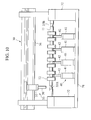
- a plasticity processing device 30 has a base section 31, a column section 32, an upper frame 25, a rail section 26, a guide rail section 34, a bending correcting section 35 and a receiving stand section 40.
- the column section 32 is arranged on both sides of the base section 31, and the guide rail section 34 is fixed to upper portions of the column sections 32.
- the column sections 32 have supporting units 33A, 33B for supporting and rotating the hollow shaft member 11, respectively.
- One 33A of the supporting units 33A, 33B is driven to the longitudinal direction (a right-left direction in Fig. 6) and the supporting unit 33B is driven to be rotated.
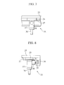
- the bending correcting section 35 as shown in Figs. 7 and 8, has a slide section 27 sliding on the rail section 26, a press rod 36, a cylinder section 37, a servomotor 38 and a roller 39.
- the press rod 36 has a plasticity processing tool for correcting the bending, and is driven by the cylinder section 37 composed of reciprocating linear movement driving means such as a hydraulic cylinder and freely moves to an up-down direction.
- the cylinder section 37 is supported to the rail section 26 and the guide rail section 34 so as to freely move.
- the servomotor 38 is mounted to the cylinder section 37. When the roller 39 which is rotated by the servomotor 38 rotates on the guide rail section 34, the cylinder section 37 moves right and left in Fig. 6.
- the press rod 36 freely approaches or separates from the hollow shaft member 11 supported by the supporting units 33A, 33B and freely moves to the longitudinal direction of the hollow shaft member 11 (shaft direction).
- the receiving stand section 40 has a cylinder section 41 and a receiving section 42.
- the receiving section 42 is driven by the cylinder section 41 composed of the reciprocating linear movement driving means such as a hydraulic cylinder so as to freely move to a desirable position in the up-down direction.
- the receiving section 42 as shown in Fig. 9, has a position sensor 43, a spring (elastic member) 44 and a contactor 45, and can detect the bending of the hollow shaft member 11.
- the spring 44 has a buffer function when the receiving section 42 comes in contact with the hollow shaft member 11 so as to be located.
- the supporting unit 33A is advanced and comes in contact with the other end of the hollow shaft member 11 so that the hollow shaft member 11 is supported.
- all the receiving stand sections 40 are operated. Namely, the respective receiving sections 42 are raised by the cylinder sections 41, respectively, so as to come in contact with the hollow shaft member 11.
- the measurement is executed by the position sensors 43 of the receiving sections 42. As a result, a position and a deforming amount in the longitudinal direction of portions of the hollow shaft member 11 requiring the bending correction are detected.
- the servomotor 38 is controlled based on the bending measured result, and the bending correcting section 35 is driven along the guide rail section 34 (the longitudinal direction of the hollow shaft member 11) so as to be located above the portion requiring the bending correction.
- the receiving stand sections 40 which are arranged on positions where the portion requiring the bending correction is sandwiched, are operated.
- the receiving sections 42 are raised to a most advancing position by the cylinder sections 41 so as to support the hollow shaft member 11.
- the press rod 36 of the bending correcting section 35 is lowered by the cylinder section 37 so as to pressurize the portion requiring the bending correction (to a direction crossing the longitudinal direction of the hollow shaft member 11) and plastically deform the portion according to a detected deforming amount. If necessary, the hollow shaft member 11 is rotated by the supporting unit 33B.
- the bending correction is repeated on all the portions requiring the bending correction so that the bending of the hollow shaft member 11 in the longitudinal direction is corrected.
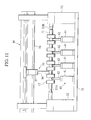
- Fig. 12 is a front view for explaining a modified example of the plasticity processing device according to the embodiment of the present invention.
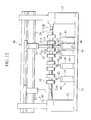
- the plasticity processing device 50 further has an upper forming section 51 and a lower forming section 54 unlike the plasticity processing device 30 shown in Figs. 6 throng 11.
- the upper forming section 51 has, for example, a press rod 52 having the plasticity processing tool 21A shown in Figs. 4 and 5, and a cylinder section 53 for driving the press rod 52, and it is used for forming the shaft fixing surface on an upper surface of the hollow shaft member 11.
- the lower forming section 54 has, for example, a press rod 55 having the plasticity processing tool 21B shown in Figs. 4 and 5, and a cylinder section 56 for driving the press rod 55, and it is used for forming the shaft fixing surface on a lower surface of the shaft fixing member 11.
- the upper forming section 51 has another servomotor and another roller similarly to the bending correcting section 35, and it freely moves along the guide rail section 34 to the longitudinal direction of the hollow shaft member 11. For this reason, the upper forming section 51 moves to a retreating position at the time of the bending correction, and thus interference between the upper forming section 51 and the bending correcting section 35 does not occur.
- the lower forming section 54 is arranged below the position between the cylinders where the shaft fixing surface is formed and between the receiving stand sections 40. Therefore, since the lower forming section 54 waits in a state that the press rod 55 is lowered at the time of the bending correction, the operation of the receiving stand sections 40 is not obstructed.
- the supporting unit 33A is advanced to a right direction in Fig. 12 so as to come in contact with the other end of the hollow shaft member 11, and thus the hollow shaft member 11 is supported.
- the upper forming section 51 moves from the retreating position to above the position between the cylinders, and the press rod 52 is lowered towards the hollow shaft member 11. Meanwhile, the lower forming section 54 raises the press rod 55 towards the hollow shaft member 11.
- the shaft fixing surfaces are formed on the portions of the hollow shaft member 11 corresponding to the position between the cylinders by the plasticity processing tools 21A, 21B of the press rod 52 and the press rod 55.
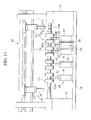
- the bending correcting step by means of the plasticity processing device 50 is similar to the bending correcting step by means of the plasticity processing device 30 except that the upper forming section 51 is arranged on the retreating position and the press rod 5 of the lower forming section 54 is lowered as shown in Fig. 13. Therefore, the explanation thereof is not repeated.
- the plasticity processing device 50 has the function for forming the shaft fixing surface and the function for correcting the bending of the hollow shaft member, and executes the surface forming step and the bending correcting step continuously in one-time chucking. Therefore, a number of the steps can be reduced and the cost of productive facilities can be reduced.
Landscapes
- Engineering & Computer Science (AREA)
- Mechanical Engineering (AREA)
- General Engineering & Computer Science (AREA)
- Valve-Gear Or Valve Arrangements (AREA)
- Gears, Cams (AREA)
- Shaping Metal By Deep-Drawing, Or The Like (AREA)
Abstract
Description
Claims (18)
- An assembled camshaft (10) for engine, comprising:a cam lobe piece (12); anda hollow shaft member (11) having at least two shaft fixing surfaces (11A) formed by plasticity process on a portion of the hollow shaft member (11) corresponding to a position between cylinders of the engine.
- An assembled camshaft (10) for engine according to claim 1, further comprising:wherein the two shaft fixing surfaces (11A) are formed on a portion of the hollow shaft member (11) between the two cam lobe pieces.another cam lobe piece (12),
- An assembled camshaft (10) for engine according to claim 1 or 2,
wherein the two shaft fixing surfaces (11A) are located on a portion of the hollow shaft member (11) at middle portion between the two cam lobe pieces (12). - An assembled camshaft (10) for engine according to any one claim among the precedent claims 1 to 3,
wherein a diameter of the portion provided with said shaft fixing surface (11A) is smaller than a diameter of said hollow shaft member (11). - An assembled camshaft (10) for engine according to any one claim among the precedent claims 1 to 4,
wherein the shaft fixing surfaces (11A) are separated by not less than 6 mm from an end surface of an adjacent cam lobe piece (12). - An assembled camshaft (10) for engine according to any one claim among the precedent claims 1 to 5,
wherein at least two of the shaft fixing surfaces (11A) are formed parallel and facing each other. - An assembled camshaft (10) for engine according to any one claim among the precedent claims 1 to 6,
wherein a cross section of the portion of said hollow shaft member (11) provided with the shaft fixing surface(11A) has a polygonal shape. - A production method of an assembled camshaft (10) for engine having a cam lobe piece (12) and a hollow shaft member (11), comprising the step of:forming at least two shaft fixing surfaces (11A) on a portion of the hollow shaft member (11) using a plasticity processing tool at a portion of the hollow shaft member (11) corresponding to a position between cylinders of the engine.
- A production method of an assembled camshaft for engine according to claim 8,
wherein the two shaft fixing surfaces (11A) are formed on a portion of the hollow shaft member (11) between two cam lobe pieces (12) in case the hollow shaft member (11) have two cam lobe pieces (12). - A production method of an assembled camshaft for engine according to claim 8 or 9,
wherein the two shaft fixing surfaces (11A) are located on a portion of the hollow shaft member (11) at middle portion between the two cam lobe pieces (12). - A production method of an assembled camshaft (10) for engine according to any one claim among the precedent claims 8 to 10, further comprising the step of:wherein the forming step to form the shaft fixing surfaces (11A) is executed after the expanding step to expand the mouth of the hollow shaft member (11).expanding a mouth of said hollow shaft member (11) so that the cam lobe piece (12) is fastened to the hollow shaft member (11),
- A production method of the assembled camshaft (10) for engine according to any one claim among the precedent claims 8 to 11, further comprising:wherein the forming step to form the shaft fixing surfaces (11A) is executed before the correcting step correcting the hollow shaft member (11) to be straight.correcting the hollow shaft member (11) to be straight,
- A production method of the assembled camshaft (10) for engine according to any one claim among the precedent claims 8 to 12, further comprising:wherein the forming step to form the shaft fixing surfaces (11A) and the correcting step to correct the hollow shaft member (11) to be straight are executed in a state that said hollow shaft member (11) is continuously fixed to a producing device (30, 50).correcting the hollow shaft member (11) to be straight,
- A production method of the assembled camshaft (10) for engine according to any one claim among the precedent claims 8 to 13,
wherein the correcting step to correct the hollow shaft member (11) to be straight comprises the steps of:measuring bent status of the hollow shaft member (11);detecting correction portion and correction amount of the hollow shaft member (11) which is to be corrected based on a measured result measured at the measuring step; andpressurizing by a plasticity processing tool (36) to a direction crossing a longitudinal direction of the hollow shaft member so that the hollow shaft member (11) is plastically deformed so as to be straight. - An assembled camshaft (10) for engine, comprising:wherein the assembled camshaft (10) is produced by the following step:a cam lobe piece (12); anda hollow shaft member (11) having at least two shaft fixing surfaces (11A),forming at least two shaft fixing surfaces (11A) on a portion of the hollow shaft member (11) using a plasticity processing tool (21A, 21B) at a portion of the hollow shaft member (11) corresponding to a position between cylinders of the engine.
- An assembled camshaft (10) for engine according to claim 15,
wherein before the shaft fixing surfaces (11A) are formed, the mouth of the hollow shaft member (11) is expanded so that the cam lobe piece (12) is fixed to the hollow shaft member (11) . - An assembled camshaft (10) for engine according to claim 15 or 16,
wherein before the shaft fixing surfaces (11A) are formed, the hollow shaft member (11) is corrected to be straight, after the cam lobe piece (12) is fixed to the hollow shaft member (11). - An assembled camshaft (10) for engine according to any one claim among the precedent claims 15 to 17,
wherein the correcting operation to correct the hollow shaft member (11) to be straight comprises the steps of:measuring bent status of the hollow shaft member (11);detecting correction portion and correction amount of the hollow shaft member (11) which is to be corrected based on a measured result measured at the measuring step; andpressurizing by a plasticity processing tool (36) to a direction crossing a longitudinal direction of the hollow shaft member (11) so that the hollow shaft member (11) is plastically deformed so as to be straight.
Applications Claiming Priority (2)
| Application Number | Priority Date | Filing Date | Title |
|---|---|---|---|
| JP2002172952A JP4075478B2 (en) | 2002-06-13 | 2002-06-13 | Assembled camshaft for engine and manufacturing method thereof |
| JP2002172952 | 2002-06-13 |
Publications (3)
| Publication Number | Publication Date |
|---|---|
| EP1371816A2 true EP1371816A2 (en) | 2003-12-17 |
| EP1371816A3 EP1371816A3 (en) | 2007-09-26 |
| EP1371816B1 EP1371816B1 (en) | 2012-02-01 |
Family
ID=29561799
Family Applications (1)
| Application Number | Title | Priority Date | Filing Date |
|---|---|---|---|
| EP03009527A Expired - Lifetime EP1371816B1 (en) | 2002-06-13 | 2003-04-28 | Assembled Camshaft for Engine and Production Method Thereof |
Country Status (4)
| Country | Link |
|---|---|
| US (1) | US7246588B2 (en) |
| EP (1) | EP1371816B1 (en) |
| JP (1) | JP4075478B2 (en) |
| CN (1) | CN1296602C (en) |
Cited By (3)
| Publication number | Priority date | Publication date | Assignee | Title |
|---|---|---|---|---|
| EP1593880A1 (en) * | 2004-05-03 | 2005-11-09 | Bayerische Motoren Werke Aktiengesellschaft | Control shaft of a lift-variable valve drive |
| EP3153247A1 (en) * | 2015-10-07 | 2017-04-12 | Otics Corporation | Method of manufacturing pipe member |
| DE102018121302A1 (en) * | 2018-08-31 | 2020-03-05 | Thyssenkrupp Ag | Straightening method for correcting a camshaft shape deviation, using a mandrel and camshaft |
Families Citing this family (10)
| Publication number | Priority date | Publication date | Assignee | Title |
|---|---|---|---|---|
| JP2007196249A (en) * | 2006-01-25 | 2007-08-09 | Nishio Seimitsu Kk | Method for manufacturing special shape plate member |
| DE102010048225B4 (en) * | 2010-10-12 | 2021-03-18 | Neumayer Tekfor Engineering Gmbh | Production of a functional shaft |
| CN103032120B (en) * | 2011-09-29 | 2015-08-26 | 北京有色金属研究总院 | A kind of powder metallurgy multiple mounted cam sheet |
| DE102012016357A1 (en) * | 2012-08-16 | 2014-02-20 | Neumayer Tekfor Holding Gmbh | Method for producing a camshaft module and corresponding camshaft module |
| CN103406792B (en) * | 2013-08-26 | 2016-05-18 | 绵阳华晨瑞安汽车零部件有限公司 | Combined camshaft tensioner machine |
| KR101850005B1 (en) * | 2016-04-05 | 2018-04-18 | 자동차부품연구원 | Cam shaft apparatus and its manufacturing method |
| CN109415954A (en) * | 2016-07-08 | 2019-03-01 | 上海尤顺汽车部件有限公司 | Engine, camshaft and method for manufacturing the same |
| CN107587908A (en) * | 2016-07-08 | 2018-01-16 | 上海尤顺汽车部件有限公司 | Engine and its camshaft, the manufacture method of camshaft |
| CN106870056A (en) * | 2017-03-01 | 2017-06-20 | 绵阳深度数控科技有限公司 | Cam pack structure |
| CN110871341A (en) * | 2018-08-31 | 2020-03-10 | 蒂森克虏伯发动机系统(大连)有限公司 | Method for producing toothed camshaft |
Family Cites Families (15)
| Publication number | Priority date | Publication date | Assignee | Title |
|---|---|---|---|---|
| US1527456A (en) * | 1924-02-29 | 1925-02-24 | Woydt Edward | Valve-operating means |
| DE2546802C3 (en) * | 1975-10-18 | 1979-08-09 | Kloeckner-Humboldt-Deutz Ag, 5000 Koeln | Cam wager for reciprocating engines |
| JPS5916634A (en) * | 1982-07-19 | 1984-01-27 | Riken Corp | Connection structure of tubular member and ring part and its connection method |
| US4597365A (en) * | 1985-02-07 | 1986-07-01 | General Motors Corporation | Camshaft assembly and method |
| US5259268A (en) * | 1987-02-10 | 1993-11-09 | Gesenkschmiede Schneider Gmbh | Hollowshaft and method for the production thereof |
| DE3736453A1 (en) * | 1987-10-28 | 1989-05-11 | Schwaebische Huettenwerke Gmbh | METHOD FOR PRODUCING A CAMSHAFT |
| WO1992002739A1 (en) * | 1990-07-27 | 1992-02-20 | Mettler Friedli Karl | Assembly of a cylindrical body made to finished dimensions |
| FR2698303B1 (en) * | 1992-11-24 | 1994-12-23 | Sintertech | Method for hooping at least one metal part having an annular bore around a metal tube, assembly obtained and use of the method. |
| JPH08210110A (en) * | 1995-01-31 | 1996-08-20 | Nippon Piston Ring Co Ltd | Manufacture of assembled camshaft |
| JPH08290220A (en) * | 1995-04-18 | 1996-11-05 | Mazda Motor Corp | Hollow camshaft manufacturing method |
| JPH11270307A (en) | 1998-03-24 | 1999-10-05 | Nippon Seiko Kk | Assembled camshaft for engine |
| DE19831333A1 (en) * | 1998-07-13 | 2000-01-27 | Neumayer Erich Gmbh Co Kg | Mounting components on hollow shaft, especially cams on camshaft, by introducing supports between components fitted onto shaft prior to shaft expansion step |
| JP2000045715A (en) * | 1998-07-24 | 2000-02-15 | Toyota Motor Corp | Manufacturing method of assembled camshaft |
| CN2422449Y (en) * | 2000-04-30 | 2001-03-07 | 李传彬 | Composite hollow camshaft |
| US6935292B2 (en) * | 2001-11-27 | 2005-08-30 | Thyssenkrupp Presta Ag | Camshaft with curvature |
-
2002
- 2002-06-13 JP JP2002172952A patent/JP4075478B2/en not_active Expired - Fee Related
-
2003
- 2003-04-28 EP EP03009527A patent/EP1371816B1/en not_active Expired - Lifetime
- 2003-05-09 US US10/434,338 patent/US7246588B2/en not_active Expired - Fee Related
- 2003-06-13 CN CNB031425739A patent/CN1296602C/en not_active Expired - Fee Related
Cited By (3)
| Publication number | Priority date | Publication date | Assignee | Title |
|---|---|---|---|---|
| EP1593880A1 (en) * | 2004-05-03 | 2005-11-09 | Bayerische Motoren Werke Aktiengesellschaft | Control shaft of a lift-variable valve drive |
| EP3153247A1 (en) * | 2015-10-07 | 2017-04-12 | Otics Corporation | Method of manufacturing pipe member |
| DE102018121302A1 (en) * | 2018-08-31 | 2020-03-05 | Thyssenkrupp Ag | Straightening method for correcting a camshaft shape deviation, using a mandrel and camshaft |
Also Published As
| Publication number | Publication date |
|---|---|
| JP4075478B2 (en) | 2008-04-16 |
| US7246588B2 (en) | 2007-07-24 |
| EP1371816B1 (en) | 2012-02-01 |
| CN1469031A (en) | 2004-01-21 |
| CN1296602C (en) | 2007-01-24 |
| JP2004019494A (en) | 2004-01-22 |
| US20030230260A1 (en) | 2003-12-18 |
| EP1371816A3 (en) | 2007-09-26 |
Similar Documents
| Publication | Publication Date | Title |
|---|---|---|
| EP1371816B1 (en) | Assembled Camshaft for Engine and Production Method Thereof | |
| US6332604B1 (en) | Clamping and positioning mechanism for the inclined axis of two-axes rotary tables | |
| CN101934470B (en) | Press-fit device | |
| CN101659014B (en) | Prestressed boring bar clamp for processing camshaft holes of diesel engine | |
| EP2153934B1 (en) | Jig and method for processing a cylinder block | |
| EP2670991B1 (en) | Rolling bearing for belt tensioning roller device | |
| JP4421530B2 (en) | Valve guide and valve seat press-fitting device | |
| KR101069339B1 (en) | Roller hemming unit of roller hemming apparatus | |
| CN110860881A (en) | Press-fit device for timing sprocket on crankshaft | |
| CN219818715U (en) | Bush press-fitting equipment | |
| KR100463039B1 (en) | Pneumatic Type Bearing Caulking Device for Universal Joint | |
| US11376651B2 (en) | Floatingly mounted multi-piece rolling tool, and rolling machine | |
| JP4745295B2 (en) | Rolling dies | |
| US4907480A (en) | Turret punch press machine | |
| JP2005199378A (en) | Honing method for inner peripheral surface of cylinder bore and honing device for inner peripheral surface of cylinder bore | |
| KR102220697B1 (en) | Clamping device to prevent bending of body skins on motor vehicles | |
| CN111946460B (en) | Guiding device for assembling fan assembly of aircraft engine and assembling method | |
| CN211249046U (en) | Press mounting device for timing chain wheel on crank of crankshaft | |
| CN109013794B (en) | Intelligent bushing mouth multipoint flattening device capable of preventing bushing from being separated | |
| CN103934477A (en) | Bearing turning feeding mechanism | |
| JP4222270B2 (en) | Caulking device operating mechanism | |
| JP4494833B2 (en) | Internal surface processing method and internal surface processing apparatus | |
| JP2000246352A (en) | Censoring flange part processing method | |
| CN219448286U (en) | Sensor detection device | |
| JP3466225B2 (en) | Press machine |
Legal Events
| Date | Code | Title | Description |
|---|---|---|---|
| PUAI | Public reference made under article 153(3) epc to a published international application that has entered the european phase |
Free format text: ORIGINAL CODE: 0009012 |
|
| 17P | Request for examination filed |
Effective date: 20030428 |
|
| AK | Designated contracting states |
Kind code of ref document: A2 Designated state(s): AT BE BG CH CY CZ DE DK EE ES FI FR GB GR HU IE IT LI LU MC NL PT RO SE SI SK TR |
|
| AX | Request for extension of the european patent |
Extension state: AL LT LV MK |
|
| PUAL | Search report despatched |
Free format text: ORIGINAL CODE: 0009013 |
|
| AK | Designated contracting states |
Kind code of ref document: A3 Designated state(s): AT BE BG CH CY CZ DE DK EE ES FI FR GB GR HU IE IT LI LU MC NL PT RO SE SI SK TR |
|
| AX | Request for extension of the european patent |
Extension state: AL LT LV MK |
|
| 17Q | First examination report despatched |
Effective date: 20080219 |
|
| AKX | Designation fees paid |
Designated state(s): DE FR GB |
|
| GRAP | Despatch of communication of intention to grant a patent |
Free format text: ORIGINAL CODE: EPIDOSNIGR1 |
|
| GRAS | Grant fee paid |
Free format text: ORIGINAL CODE: EPIDOSNIGR3 |
|
| GRAA | (expected) grant |
Free format text: ORIGINAL CODE: 0009210 |
|
| AK | Designated contracting states |
Kind code of ref document: B1 Designated state(s): DE FR GB |
|
| REG | Reference to a national code |
Ref country code: GB Ref legal event code: FG4D |
|
| REG | Reference to a national code |
Ref country code: DE Ref legal event code: R096 Ref document number: 60339878 Country of ref document: DE Effective date: 20120329 |
|
| PLBE | No opposition filed within time limit |
Free format text: ORIGINAL CODE: 0009261 |
|
| STAA | Information on the status of an ep patent application or granted ep patent |
Free format text: STATUS: NO OPPOSITION FILED WITHIN TIME LIMIT |
|
| 26N | No opposition filed |
Effective date: 20121105 |
|
| REG | Reference to a national code |
Ref country code: DE Ref legal event code: R097 Ref document number: 60339878 Country of ref document: DE Effective date: 20121105 |
|
| PGFP | Annual fee paid to national office [announced via postgrant information from national office to epo] |
Ref country code: GB Payment date: 20140423 Year of fee payment: 12 |
|
| PGFP | Annual fee paid to national office [announced via postgrant information from national office to epo] |
Ref country code: FR Payment date: 20140409 Year of fee payment: 12 Ref country code: DE Payment date: 20140430 Year of fee payment: 12 |
|
| REG | Reference to a national code |
Ref country code: DE Ref legal event code: R119 Ref document number: 60339878 Country of ref document: DE |
|
| GBPC | Gb: european patent ceased through non-payment of renewal fee |
Effective date: 20150428 |
|
| PG25 | Lapsed in a contracting state [announced via postgrant information from national office to epo] |
Ref country code: GB Free format text: LAPSE BECAUSE OF NON-PAYMENT OF DUE FEES Effective date: 20150428 Ref country code: DE Free format text: LAPSE BECAUSE OF NON-PAYMENT OF DUE FEES Effective date: 20151103 |
|
| REG | Reference to a national code |
Ref country code: FR Ref legal event code: ST Effective date: 20151231 |
|
| PG25 | Lapsed in a contracting state [announced via postgrant information from national office to epo] |
Ref country code: FR Free format text: LAPSE BECAUSE OF NON-PAYMENT OF DUE FEES Effective date: 20150430 |