EP1371564A1 - Method and machine for packing a product using a flat tubular package - Google Patents
Method and machine for packing a product using a flat tubular package Download PDFInfo
- Publication number
- EP1371564A1 EP1371564A1 EP03013070A EP03013070A EP1371564A1 EP 1371564 A1 EP1371564 A1 EP 1371564A1 EP 03013070 A EP03013070 A EP 03013070A EP 03013070 A EP03013070 A EP 03013070A EP 1371564 A1 EP1371564 A1 EP 1371564A1
- Authority
- EP
- European Patent Office
- Prior art keywords
- tubular package
- gripping head
- suction
- flat
- seat
- Prior art date
- Legal status (The legal status is an assumption and is not a legal conclusion. Google has not performed a legal analysis and makes no representation as to the accuracy of the status listed.)
- Granted
Links
- 238000000034 method Methods 0.000 title claims abstract description 19
- 238000012856 packing Methods 0.000 title claims abstract description 11
- 235000019504 cigarettes Nutrition 0.000 claims abstract description 19
- 238000003780 insertion Methods 0.000 claims description 8
- 230000037431 insertion Effects 0.000 claims description 8
- 238000012546 transfer Methods 0.000 claims description 5
- 238000013519 translation Methods 0.000 claims description 3
- 230000014616 translation Effects 0.000 claims description 3
- 230000002441 reversible effect Effects 0.000 claims description 2
- 230000003287 optical effect Effects 0.000 description 2
- 230000000737 periodic effect Effects 0.000 description 1
Images



Classifications
-
- B—PERFORMING OPERATIONS; TRANSPORTING
- B65—CONVEYING; PACKING; STORING; HANDLING THIN OR FILAMENTARY MATERIAL
- B65B—MACHINES, APPARATUS OR DEVICES FOR, OR METHODS OF, PACKAGING ARTICLES OR MATERIALS; UNPACKING
- B65B5/00—Packaging individual articles in containers or receptacles, e.g. bags, sacks, boxes, cartons, cans, jars
- B65B5/06—Packaging groups of articles, the groups being treated as single articles
-
- B—PERFORMING OPERATIONS; TRANSPORTING
- B31—MAKING ARTICLES OF PAPER, CARDBOARD OR MATERIAL WORKED IN A MANNER ANALOGOUS TO PAPER; WORKING PAPER, CARDBOARD OR MATERIAL WORKED IN A MANNER ANALOGOUS TO PAPER
- B31B—MAKING CONTAINERS OF PAPER, CARDBOARD OR MATERIAL WORKED IN A MANNER ANALOGOUS TO PAPER
- B31B50/00—Making rigid or semi-rigid containers, e.g. boxes or cartons
- B31B50/74—Auxiliary operations
- B31B50/76—Opening and distending flattened articles
- B31B50/80—Pneumatically
-
- B—PERFORMING OPERATIONS; TRANSPORTING
- B65—CONVEYING; PACKING; STORING; HANDLING THIN OR FILAMENTARY MATERIAL
- B65B—MACHINES, APPARATUS OR DEVICES FOR, OR METHODS OF, PACKAGING ARTICLES OR MATERIALS; UNPACKING
- B65B43/00—Forming, feeding, opening or setting-up containers or receptacles in association with packaging
- B65B43/12—Feeding flexible bags or carton blanks in flat or collapsed state; Feeding flat bags connected to form a series or chain
- B65B43/14—Feeding individual bags or carton blanks from piles or magazines
- B65B43/16—Feeding individual bags or carton blanks from piles or magazines by grippers
- B65B43/18—Feeding individual bags or carton blanks from piles or magazines by grippers by suction-operated grippers
- B65B43/185—Feeding individual bags or carton blanks from piles or magazines by grippers by suction-operated grippers specially adapted for carton blanks
-
- B—PERFORMING OPERATIONS; TRANSPORTING
- B65—CONVEYING; PACKING; STORING; HANDLING THIN OR FILAMENTARY MATERIAL
- B65B—MACHINES, APPARATUS OR DEVICES FOR, OR METHODS OF, PACKAGING ARTICLES OR MATERIALS; UNPACKING
- B65B43/00—Forming, feeding, opening or setting-up containers or receptacles in association with packaging
- B65B43/26—Opening or distending bags; Opening, erecting, or setting-up boxes, cartons, or carton blanks
- B65B43/30—Opening or distending bags; Opening, erecting, or setting-up boxes, cartons, or carton blanks by grippers engaging opposed walls, e.g. suction-operated
- B65B43/305—Opening or distending bags; Opening, erecting, or setting-up boxes, cartons, or carton blanks by grippers engaging opposed walls, e.g. suction-operated specially adapted for boxes, cartons or carton blanks
-
- B—PERFORMING OPERATIONS; TRANSPORTING
- B31—MAKING ARTICLES OF PAPER, CARDBOARD OR MATERIAL WORKED IN A MANNER ANALOGOUS TO PAPER; WORKING PAPER, CARDBOARD OR MATERIAL WORKED IN A MANNER ANALOGOUS TO PAPER
- B31B—MAKING CONTAINERS OF PAPER, CARDBOARD OR MATERIAL WORKED IN A MANNER ANALOGOUS TO PAPER
- B31B50/00—Making rigid or semi-rigid containers, e.g. boxes or cartons
- B31B50/006—Controlling; Regulating; Measuring; Improving safety
Definitions
- the present invention relates to a method of packing a product using a flat tubular package.
- the present invention may be used to advantage on a machine for boxing cartons of cigarettes, i.e. a machine on which groups of cartons of cigarettes are packed in respective boxes, to which the following description refers purely by way of example.
- Currently known machines for boxing cartons of cigarettes comprise a unit for supplying and opening flat tubular packages, and which receives a stack of flat tubular packages off a pallet, and feeds each flat tubular package to a respective seat on a conveyor, by which the tubular package is fed along a straight packing path.
- each tubular package remains connected to the respective seat, and is fed through an opening station, where the tubular package is opened into a configuration suitable for receiving a respective group of cartons of cigarettes; through an insertion station, where a respective group of cartons of cigarettes is pushed inside the open tubular package; and, finally, through a closing station, where the tubular package is closed by gumming and folding the relative flaps.
- a method of packing a product using a flat tubular package which comprises a top wall, a bottom wall, and two lateral walls, each connected on one side to the top wall and on the other side to the bottom wall; the method being characterized by comprising the steps of: engaging the top wall of the flat tubular package by suction using a gripping head; moving the gripping head to feed the flat tubular package to a seat engaging the bottom wall of the flat tubular package by suction; producing a relative rotation movement between the seat and the gripping head to convert the tubular package from the flat configuration to an open configuration; and inserting the product inside the open tubular package.
- the present invention also relates to a machine for packing a product using a flat tubular package.
- a machine for packing a product using a flat tubular package which comprises a top wall, a bottom wall, and two lateral walls, each connected on one side to the top wall and on the other side to the bottom wall; the machine being characterized by comprising a suction gripping head for engaging the top wall of the flat tubular package; a suction seat for engaging the bottom wall of the flat tubular package; a feed device supporting the gripping head, and for moving the gripping head to feed the flat tubular package to the suction seat, and for producing a relative rotation movement between the suction seat and the gripping head to convert the tubular package from the flat configuration to an open configuration; and an insertion device for inserting the product inside the open tubular package.
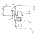
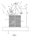
- Number 1 in Figure 1 indicates as a whole a boxing machine for boxing groups 2 of cartons of cigarettes; which machine 1 provides for inserting each group 2 of cartons of cigarettes into a respective tubular package 3 comprising a top wall 4, a bottom wall 5, and two lateral walls 6, each connected on one side to top wall 4 and on the other side to bottom wall 5 (as shown in Figures 5-8).
- Boxing machine 1 comprises an input station 7, which houses a pallet 8 supporting two stacks 9 of flat tubular packages 3, i.e. tubular packages 3 pressed into a flat configuration; and each flat tubular package 3 in each stack 9 lies in a horizontal plane.
- Boxing machine 1 also comprises a suction gripping head 10 for engaging top wall 4 of the top flat tubular package 3 in one of stacks 9; a suction seat 11 for engaging bottom wall 5 of tubular package 3; and a feed device 12 supporting gripping head 10, and for moving gripping head 10 to feed flat tubular package 3 to seat 11.
- suction gripping head 10 comprises a suction portion 13 for engaging top wall 4 of a tubular package 3; and a suction portion 14 for engaging a lateral wall 6 of a tubular package 3.
- feed device 12 moves gripping head 10 with four degrees of freedom comprising three translations in three directions perpendicular to one another, and one rotation about a vertical axis 15 perpendicular to the horizontal plane of flat tubular package 3. More specifically, feed device 12 comprises a base 16 supporting a powered articulated arm 17 in turn comprising two members 18 and 19 hinged to each other; member 18 is hinged at one end to base 16 to rotate, with respect to base 16, about a horizontal axis 20, and is hinged at the opposite end to member 19 to rotate, with respect to member 19, about a horizontal axis 21 parallel to axis 20; member 19 is hinged at one end to member 18 to rotate, with respect to member 18, about horizontal axis 21, and is hinged at the opposite end to a powered articulated joint 22 to rotate, with respect to articulated joint 22, about a horizontal axis 23 parallel to axes 20 and 21; and articulated joint 22 is hinged, on one side, to member 19 to rotate, with respect to member 19, about axis 23, and
- Articulated arm 17 is powered to keep suction gripping head 10 horizontal at all times and therefore parallel to the plane of flat tubular packages 3; the movement of articulated arm 17 moves suction gripping head 10 parallel to itself in a vertical plane perpendicular to axes 20, 21 and 23; and base 16 is run, by a respective known motor (not shown), along a horizontal guide 24 parallel to axes 20, 21 and 23 to move suction gripping head 10 in a direction parallel to axes 20, 21 and 23.
- Suction gripping head 10 comprises a known optical sensor 25 for determining the exact position of the top flat tubular package 3 in stack 9, before flat tubular package 3 is engaged; and a known control unit (not shown) is provided to control feed device 12 supporting suction gripping head 10, so as to adapt the position of suction gripping head 10 to the exact detected position of flat tubular package 3, and engage flat tubular package 3 in accordance with a predetermined mutual arrangement, so that feed device 12 operates correctly even in the event flat tubular packages 3 are not positioned correctly in stacks 9.
- suction seat 11 is supported by a linear conveyor 26 for moving seat 11 between a receiving station 27 for receiving a tubular package 3 (as shown in Figure 1), and a transfer position (not shown) wherein seat 11 is located close to a known closing station 28 (shown schematically in Figure 1) where a known transfer device (not shown) is provided to transfer an open tubular package 3 containing the group of cartons of cigarettes from suction seat 11 to closing station 28.
- linear conveyor 26 comprises a fixed guide 29 along which suction seat 11 runs; and a known reversible motor (not shown) for moving suction seat 11 along fixed guide 29.
- conveyor 26 comprises an endless moving belt supporting and for moving a number of suction seats 11 cyclically along an endless path through receiving station 27 and closing station 28.
- suction seat 11 is mounted in a fixed position at receiving station 27, and a push device is provided to transfer an open tubular package 3 containing a respective group 2 of cartons of cigarettes from suction seat 11 to closing station 28.
- boxing machine 1 comprises an insertion device 30 located close to receiving station 27 and for inserting a group 2 of cartons of cigarettes into an open tubular package 3 located at receiving station 27 and supported by suction seat 11.
- Insertion device 30 comprises a conveyor 31 for feeding groups 2 of cartons of cigarettes successively into alignment with respect to the open tubular package 3 at receiving station 27; and a pusher 32 for pushing group 2 of cartons of cigarettes into open tubular package 3.
- boxing machine 1 Operation of boxing machine 1 will now be described with reference to a flat tubular package 3 on top of a stack 9, and to a respective group 2 of cartons of cigarettes.
- feed device 12 moves suction head 10 to engage flat tubular package 3, so that portion 13 of suction head 10 engages top wall 4 of flat tubular package 3, and suction portion 14 of suction head 10 engages lateral wall 6 of flat tubular package 3. More specifically, feed device 12 moves suction head 10 over to the estimated (i.e. best-condition) position of flat tubular package 3; by means of optical sensor 25, suction gripping head 10 then determines the real position of flat tubular package 3; and, on the basis of the real position of flat tubular package 3, feed device 12 is operated to adapt the position of suction gripping head 10 to the real position of flat tubular package 3, and so enable gripping head 10 to engage flat tubular package 3 in accordance with a given mutual arrangement.
- Feed device 12 then moves suction gripping head 10, together with flat tubular package 3, over to receiving station 27 to feed flat tubular package 3 to suction seat 11, which engages the bottom wall 5 of flat tubular package 3; at which stage, flat tubular package 3 is engaged simultaneously by suction head 10 and suction seat 11.
- suction gripping head 10 is rotated 90° about vertical axis 15 to similarly rotate flat tubular package 3 into the correct position for supply to suction seat 11.
- a relative rotation movement is then produced between suction seat 11 and gripping head 10 to convert tubular package 3 from the flat configuration to an open configuration. More specifically, the relative rotation movement is preferably produced by keeping suction seat 11 stationary and moving gripping head 10. Alternatively, the relative rotation movement may be produced by moving suction seat 11 horizontally and gripping head 10 vertically.
- suction portion 14 is hinged to suction portion 13, and suction gripping head 10 comprises a known actuator (not shown) for keeping suction portion 14 parallel to suction portion 13 up to the step of producing a relative rotation movement between seat 11 and gripping head 10, and for rotating second suction portion 14 with respect to first suction portion 13, so as to accompany the rotation of lateral wall 6 to convert tubular package 3 from the flat configuration to the open configuration.
- insertion device 30 inserts group 2 of cartons of cigarettes inside the open tubular package 3; gripping head 10 then releases top wall 4 of the open tubular package 3; seat 11 is moved to feed package 3 to closing station 28; the open tubular package 3 containing group 2 of cartons of cigarettes is transferred from seat 11 to the closing station; and seat 11 is then returned to receiving station 27 to receive another flat tubular package 3 from suction head 10.
- Boxing machine 1 as described above has countless advantages, by being relatively straightforward and compact, and by not requiring a precise position of tubular packages 3 in stacks 9, which can therefore be supplied fully automatically.
Landscapes
- Engineering & Computer Science (AREA)
- Mechanical Engineering (AREA)
- Supplying Of Containers To The Packaging Station (AREA)
- Container Filling Or Packaging Operations (AREA)
Abstract
Description
Claims (28)
- A method of packing a product using a flat tubular package, which comprises a top wall (4), a bottom wall (5), and two lateral walls (6), each connected on one side to the top wall (4) and on the other side to the bottom wall (5); the method being characterized by comprising the steps of: engaging the top wall (4) of the flat tubular package (3) by suction using a gripping head (10); moving the gripping head (10) to feed the flat tubular package (3) to a seat (11) engaging the bottom wall (5) of the flat tubular package (3) by suction; producing a relative rotation movement between the seat (11) and the gripping head (10) to convert the tubular package (3) from the flat configuration to an open configuration; and inserting the product (2) inside the open tubular package (3).
- A method as claimed in Claim 1, characterized in that, following the step of inserting the product (2) inside the open tubular package (3), the gripping head (10) releases the top wall (4) of the open tubular package (3), and the seat (11) is moved to feed the package (3) to a closing station (28).
- A method as claimed in Claim 2, characterized in that the open tubular package (3) containing the product (2) is transferred from the seat (11) to the closing station (28), and the seat (11) is then returned to the initial position to receive another flat tubular package (3).
- A method as claimed in Claim 1, characterized in that, following the step of inserting the product (2) inside the open tubular package (3), the gripping head (10) releases the top wall (4) of the open tubular package (3), and the seat (11) is moved to feed the package (3) through a closing station (28).
- A method as claimed in Claim 1, characterized in that, following the step of inserting the product (2) inside the open tubular package (3), the gripping head (10) and the seat (11) release the open tubular package (3), and the open tubular package (3) is transferred to a closing station (28) by means of a pusher.
- A method as claimed in one of Claims 1 to 5, characterized in that the flat tubular package (3) is removed by the gripping head (10) off a stack (9) of flat tubular packages (3).
- A method as claimed in Claim 6, characterized in that, during the step of moving the gripping head (10) to feed the flat tubular package (3) to the seat (11), the flat tubular package (3) is rotated 90° about an axis (15) perpendicular to the plane of the flat tubular package (3).
- A method as claimed in Claim 6 or 7, characterized in that, before engaging the flat tubular package (3) on top of the stack (9), the gripping head (10) determines the exact position of the flat tubular package (3), and adapts its own position accordingly, so as to engage the flat tubular package (3) in accordance with a predetermined mutual arrangement.
- A method as claimed in Claim 8, characterized in that the gripping head (10) is moved with four degrees of freedom comprising three translations in three directions perpendicular to one another, and one rotation about an axis (15) perpendicular to the plane of the flat tubular package (3).
- A method as claimed in any one of Claims 1 to 9, characterized in that the gripping head (10) engages by suction both the top wall (4) and a lateral wall (6) of the flat tubular package (3); and the gripping head (10) releases the lateral wall (6) of the flat tubular package (3) prior to the step of producing a relative rotation movement between the seat (11) and the gripping head (10) to convert the tubular package (3) from the flat configuration to the open configuration.
- A method as claimed in any one of Claims 1 to 9, characterized in that the gripping head (10) comprises a first suction portion (13) for engaging the top wall (4), and a second suction portion (14) hinged to the first suction portion (13) and for engaging the lateral wall (6); the gripping head (10) engaging by suction both the top wall (4) and a lateral wall (6) of the flat tubular package (3); the second suction portion (14) being kept parallel to the first suction portion (13) up to the step of producing a relative rotation movement between the seat (11) and the gripping head (10) to convert the tubular package (3) from the flat configuration to the open configuration; and the second suction portion (14) being rotated with respect to the first suction portion (13) to accompany the movement of the lateral wall (6) during the step of producing a relative rotation movement between the seat (11) and the gripping head (10) to convert the tubular package (3) from the flat configuration to the open configuration.
- A method as claimed in any one of Claims 1 to 11, characterized in that the product (2) is defined by a group (2) of cartons of cigarettes.
- A machine for packing a product using a flat tubular package, which comprises a top wall (4), a bottom wall (5), and two lateral walls (6), each connected on one side to the top wall (4) and on the other side to the bottom wall (5); the machine (1) being characterized by comprising a suction gripping head (10) for engaging the top wall (4) of the flat tubular package (3); a suction seat (11) for engaging the bottom wall (5) of the flat tubular package (3); a feed device (12) supporting the gripping head (10), and for moving the gripping head (10) to feed the flat tubular package (3) to the suction seat (11), and for producing a relative rotation movement between the suction seat (11) and the gripping head (10) to convert the tubular package (3) from the flat configuration to an open configuration; and an insertion device (30) for inserting the product (2) inside the open tubular package (3).
- A machine as claimed in Claim 13, characterized by comprising a closing station (28); and a conveyor (26) for moving the suction seat (11) to feed the tubular package (3) to the closing station (28) following insertion of the product (2) inside the open tubular package (3).
- A machine as claimed in Claim 14, characterized by comprising a transfer device for transferring the open tubular package (3) containing the product (2) from the suction seat (11) to the closing station (28).
- A machine as claimed in Claim 14 or 15, characterized in that the conveyor (26) comprises a fixed guide (29), along which the suction seat (11) runs; and a reversible motor for moving the suction seat (11) along the fixed guide.
- A machine as claimed in Claim 14 or 15, characterized in that the conveyor (26) comprises a moving endless belt supporting a number of said suction seats (11) and for moving the suction seats (11) cyclically along an endless path.
- A machine as claimed in Claim 13, characterized by comprising a closing station (28); and a conveyor (26) for moving the suction seat (11) to feed the open tubular package (3) containing the product (2) through the closing station (28).
- A machine as claimed in Claim 13, characterized by comprising a closing station (28); and a push device for transferring the open tubular package (3) containing the product (2) from the suction seat (11) to the closing station (28); the suction seat (11) being fitted to the machine (1) in a fixed position.
- A machine as claimed in any one of Claims 13 to 19, characterized by comprising an input station (7) housing at least one stack (9) of flat tubular packages (3), which are gradually engaged by the gripping head (10).
- A machine as claimed in Claim 20, characterized in that the gripping head (10) comprises a sensor (25) for determining the exact position of the flat tubular package (3) on top of the stack (9), before the flat tubular package (3) is engaged; a control unit being provided to control the feed device (12) supporting the gripping head (10), so as to adapt the position of the gripping head (10) as a function of the exact position determined of the flat tubular package (3), and engage the flat tubular package (3) in accordance with a predetermined mutual arrangement.
- A machine as claimed in Claim 21, characterized in that the feed device (12) moves the gripping head (10) with four degrees of freedom comprising three translations in three directions perpendicular to one another, and one rotation about an axis (15) perpendicular to the plane of the flat tubular package (3).
- A machine as claimed in Claim 20 or 21, characterized in that the plane of the flat tubular package (3) is a substantially horizontal plane; the feed device (12) comprising a base (16) supporting a powered articulated arm comprising two members hinged to each other; a first member (18) being hinged at one end to the base (16) to rotate with respect to the base (16) about a horizontal first axis (20), and being hinged at the opposite end to the second member (19) to rotate with respect to the second member (19) about a horizontal second axis (21); the second member (19) being hinged at one end to the first member (18) to rotate with respect to the first member (18) about the horizontal second axis (21), and being hinged at the opposite end to the gripping head (10) to rotate with respect to the gripping head (10) about a horizontal third axis (23).
- A machine as claimed in Claim 23, characterized in that a powered articulated joint (22) is interposed between the second member (19) and the gripping head (10), is hinged, on one side, to the second member (19), and is hinged, on the opposite side, to the gripping head (10) to rotate the gripping head (10) about a vertical axis (15).
- A machine as claimed in Claim 23 or 24, characterized in that the base (16) of the feed device (12) is mounted to run, by virtue of a respective motor, along a horizontal guide (24) parallel to the horizontal first, second and third axis (20, 21, 23).
- A machine as claimed in any one of Claims 13 to 25, characterized in that the gripping head (10) comprises a first suction portion (13) for engaging the top wall (4), and a second suction portion (14) for engaging the lateral wall (6); the suction through the first suction portion (13) being controllable independently with respect to suction through the second suction portion (14).
- A machine as claimed in any one of Claims 13 to 26, characterized in that the gripping head (10) comprises a first suction portion (13) for engaging the top wall (4), and a second suction portion (14) hinged to the first suction portion (13) and for engaging the lateral wall (6); the gripping head (10) comprising an actuator for keeping the second suction portion (14) parallel to the first suction portion (13) up to the step of producing a relative rotation movement between the suction seat (11) and the gripping head (10) to convert the tubular package (3) from the flat configuration to the open configuration, and for rotating the second suction portion (14) with respect to the first suction portion (13) to accompany the movement of the lateral wall (6) during the step of producing a relative rotation movement between the suction seat (11) and the gripping head (10) to convert the tubular package (3) from the flat configuration to the open configuration.
- A machine as claimed in any one of Claims 13 to 27, characterized in that the insertion device (30) comprises a conveyor (31) for feeding the product (2) into alignment with respect to the open tubular package (3); and a pusher (32) for pushing the product (2) into the open tubular package (3).
Applications Claiming Priority (2)
| Application Number | Priority Date | Filing Date | Title |
|---|---|---|---|
| ITBO20020379 | 2002-06-13 | ||
| IT2002BO000379A ITBO20020379A1 (en) | 2002-06-13 | 2002-06-13 | METHOD AND MACHINE FOR THE PACKAGING OF A PRODUCT USING A FLAT TUBULAR WRAPPING |
Publications (2)
| Publication Number | Publication Date |
|---|---|
| EP1371564A1 true EP1371564A1 (en) | 2003-12-17 |
| EP1371564B1 EP1371564B1 (en) | 2006-01-18 |
Family
ID=11440225
Family Applications (1)
| Application Number | Title | Priority Date | Filing Date |
|---|---|---|---|
| EP03013070A Expired - Lifetime EP1371564B1 (en) | 2002-06-13 | 2003-06-10 | Method and machine for packing a product using a flat tubular package |
Country Status (6)
| Country | Link |
|---|---|
| US (1) | US6915622B2 (en) |
| EP (1) | EP1371564B1 (en) |
| JP (1) | JP4454968B2 (en) |
| CN (1) | CN1294051C (en) |
| DE (1) | DE60303240T2 (en) |
| IT (1) | ITBO20020379A1 (en) |
Cited By (3)
| Publication number | Priority date | Publication date | Assignee | Title |
|---|---|---|---|---|
| DE102007034872A1 (en) * | 2007-07-24 | 2009-01-29 | WINKLER+DüNNEBIER AG | A method of providing upright folding cartons at the exit of a production machine and apparatus for erecting cartons of flat carton sleeves |
| EP2735515A1 (en) * | 2012-11-26 | 2014-05-28 | Pester Pac Automation GmbH | Apparatus for erecting carton blanks |
| EP3666697A1 (en) * | 2018-12-14 | 2020-06-17 | Krones Aktiengesellschaft | Packaging device, removal device and method for removing a carton blank |
Families Citing this family (35)
| Publication number | Priority date | Publication date | Assignee | Title |
|---|---|---|---|---|
| ITBO20020521A1 (en) * | 2002-08-05 | 2004-02-06 | Gd Spa | METHOD AND MACHINE FOR PACKAGING A PRODUCT |
| ITBO20050576A1 (en) * | 2005-09-23 | 2007-03-24 | Marchesini Group Spa | STATION FOR THE COLLECTION OF TUBULAR DIE CUTTERS IN CONFIGURATION APPIATTITA AND FOR THE PUTTING UP TO THE VOLUME OF THE DRAGGINGS |
| US7510517B2 (en) * | 2005-09-23 | 2009-03-31 | Prototype Equipment Corporation | Case erector apparatus |
| ITBO20070086A1 (en) * | 2007-02-15 | 2008-08-16 | Marchesini Group Spa | MACHINE FOR PACKAGING ITEMS IN CASES |
| EP2000410B1 (en) * | 2007-05-03 | 2009-07-22 | UHLMANN PAC-SYSTEME GmbH & Co. KG | Method for manufacturing supply packs with various medicines for several days |
| US7828708B2 (en) * | 2007-10-04 | 2010-11-09 | Wexxar Packaging, Inc. | Case erector and sealer apparatus |
| ITBO20080194A1 (en) * | 2008-03-27 | 2009-09-28 | Marchesini Group Spa | DEVICE FOR THE VOLUME OF TUBULAR CUTTERS IN FULL FORM |
| DE102009031298A1 (en) * | 2009-06-30 | 2011-01-05 | Konecranes Lifting Systems Gmbh | Device for unfolding pallet frames, has two parts, which are relatively moved together in defined angle on block, and rectangular suction cup accommodating article and connected with unfolding device during unfolding |
| US9149122B1 (en) | 2010-11-04 | 2015-10-06 | J Squared, Inc. | Chair palletizing method |
| JP5351946B2 (en) * | 2011-08-10 | 2013-11-27 | 株式会社安川電機 | Packing equipment |
| FR2986510B1 (en) * | 2012-02-03 | 2016-03-25 | Otor Sa | DEVICE AND METHOD FOR FORMING PACKAGING BOXES WITH VERTICAL DEPILING |
| WO2013159180A1 (en) | 2012-04-24 | 2013-10-31 | Langen H J Paul | Method and apparatus for forming containers |
| US20150324893A1 (en) | 2012-04-24 | 2015-11-12 | H. J. Paul Langen | Method and system for order fulfilment |
| US12172787B2 (en) | 2014-03-11 | 2024-12-24 | H. J. Paul Langen | Method and system for order fulfilment |
| US20180169988A1 (en) * | 2014-09-19 | 2018-06-21 | Kliklok Corporation | Carton forming machine and related methods |
| DE102014221221A1 (en) * | 2014-10-20 | 2016-04-21 | Krones Aktiengesellschaft | Apparatus and method for mounting and erecting collapsed or folded cardboard boxes to standing arranged compartments and / or outer packaging |
| US10640308B2 (en) | 2014-12-08 | 2020-05-05 | Wexxar Packaging, Inc. | Carton feeding system and method and related carton forming and sealing machine |
| JP6626411B2 (en) * | 2016-06-06 | 2019-12-25 | 川崎重工業株式会社 | Food stuffing equipment |
| US10273042B1 (en) * | 2017-07-19 | 2019-04-30 | Wayne Automation Corporation | Bi-directional carton opening system |
| JP6996734B2 (en) * | 2017-08-18 | 2022-01-17 | 株式会社イシダ | Box making device |
| US11173686B2 (en) | 2017-08-25 | 2021-11-16 | Wexxar Packaging, Inc. | Apparatus and method for accurate carton formation |
| EP3546205A1 (en) * | 2018-03-27 | 2019-10-02 | Harro Höfliger Verpackungsmaschinen GmbH | Device for transferring a folding box to a transport device |
| DE102019101816A1 (en) * | 2019-01-25 | 2020-07-30 | Sig Technology Ag | Method and device for at least partially unfolding flat-folded packaging sleeves |
| CN112297508B (en) * | 2019-07-31 | 2022-07-08 | 上海烟草集团有限责任公司 | Cardboard packaging box automatic forming device and forming method |
| US11390049B2 (en) * | 2019-11-07 | 2022-07-19 | H. J. Paul Langen | Method and apparatus for erecting cartons |
| US11752723B2 (en) | 2019-11-07 | 2023-09-12 | H. J. Paul Langen | Method and apparatus for erecting cartons and for order fulfilment and packing |
| CN110721986A (en) * | 2019-11-15 | 2020-01-24 | 楚天科技股份有限公司 | Inner membrane removing device and inner membrane removing method thereof |
| US11426965B2 (en) | 2020-07-30 | 2022-08-30 | Taiwan Semiconductor Manufacturing Co., Ltd. | Box erecting apparatus and method |
| CA3193127A1 (en) | 2020-08-28 | 2022-03-03 | H. J. Paul Langen | Warehouse system for fulfilling orders |
| US11731386B2 (en) * | 2020-11-03 | 2023-08-22 | Wayne Automation Corporation | System and method for processing case and carton blanks |
| US12473111B2 (en) | 2021-02-12 | 2025-11-18 | Afa Systems Ltd. | Method and apparatus loading of cases with items |
| JP7366465B1 (en) * | 2021-11-25 | 2023-10-23 | スターテクノ株式会社 | Box manufacturing equipment and method |
| EP4190544A1 (en) * | 2021-12-03 | 2023-06-07 | Uhlmann Pac-Systeme GmbH & Co. KG | Method and transfer device for transferring folding boxes |
| CN118679101A (en) * | 2022-02-15 | 2024-09-20 | Abb瑞士股份有限公司 | Clamp for disassembling and assembling paper box |
| CN118419349A (en) * | 2024-05-20 | 2024-08-02 | 上海松川远亿机械设备有限公司 | An intelligent system for opening and forming packaging box blanks |
Citations (3)
| Publication number | Priority date | Publication date | Assignee | Title |
|---|---|---|---|---|
| DE2250667A1 (en) * | 1972-10-16 | 1974-04-25 | Packo Gmbh | DEVICE FOR ERECTING FLAT-FOLDED PACKAGING BOXES |
| FR2532912A1 (en) * | 1982-09-15 | 1984-03-16 | Thermopac | Automatic machine for wrapping boxes or similar packages, particularly egg boxes |
| EP0734948A1 (en) * | 1995-03-30 | 1996-10-02 | MARCHESINI GROUP S.p.A. | Machine for automatic packaging of articles in containers obtained from tubular blanks |
Family Cites Families (4)
| Publication number | Priority date | Publication date | Assignee | Title |
|---|---|---|---|---|
| IT1273814B (en) * | 1994-02-24 | 1997-07-10 | Ima Spa | DEVICE FOR THE COLLECTION, THE OPENING AND THE TRANSFER TO A PACKAGING LINE OF ENVELOPES RECOVERED FROM SHEET ELEMENTS |
| JPH07290608A (en) * | 1994-04-26 | 1995-11-07 | Sony Corp | Robot hand |
| JPH10324311A (en) * | 1997-05-26 | 1998-12-08 | Gunze Ltd | Method and device for opening rectangular prismatic case |
| JP4644350B2 (en) * | 2000-10-13 | 2011-03-02 | 株式会社フジシールインターナショナル | Folding box take-out supply device |
-
2002
- 2002-06-13 IT IT2002BO000379A patent/ITBO20020379A1/en unknown
-
2003
- 2003-06-09 US US10/457,801 patent/US6915622B2/en not_active Expired - Fee Related
- 2003-06-10 EP EP03013070A patent/EP1371564B1/en not_active Expired - Lifetime
- 2003-06-10 DE DE60303240T patent/DE60303240T2/en not_active Expired - Lifetime
- 2003-06-12 CN CNB031472192A patent/CN1294051C/en not_active Expired - Fee Related
- 2003-06-12 JP JP2003168001A patent/JP4454968B2/en not_active Expired - Fee Related
Patent Citations (3)
| Publication number | Priority date | Publication date | Assignee | Title |
|---|---|---|---|---|
| DE2250667A1 (en) * | 1972-10-16 | 1974-04-25 | Packo Gmbh | DEVICE FOR ERECTING FLAT-FOLDED PACKAGING BOXES |
| FR2532912A1 (en) * | 1982-09-15 | 1984-03-16 | Thermopac | Automatic machine for wrapping boxes or similar packages, particularly egg boxes |
| EP0734948A1 (en) * | 1995-03-30 | 1996-10-02 | MARCHESINI GROUP S.p.A. | Machine for automatic packaging of articles in containers obtained from tubular blanks |
Cited By (4)
| Publication number | Priority date | Publication date | Assignee | Title |
|---|---|---|---|---|
| DE102007034872A1 (en) * | 2007-07-24 | 2009-01-29 | WINKLER+DüNNEBIER AG | A method of providing upright folding cartons at the exit of a production machine and apparatus for erecting cartons of flat carton sleeves |
| DE102007034872B4 (en) * | 2007-07-24 | 2010-07-29 | WINKLER+DüNNEBIER AG | A method of providing upright cartons at the exit of a production machine and folding cartons filled with pallets |
| EP2735515A1 (en) * | 2012-11-26 | 2014-05-28 | Pester Pac Automation GmbH | Apparatus for erecting carton blanks |
| EP3666697A1 (en) * | 2018-12-14 | 2020-06-17 | Krones Aktiengesellschaft | Packaging device, removal device and method for removing a carton blank |
Also Published As
| Publication number | Publication date |
|---|---|
| US6915622B2 (en) | 2005-07-12 |
| ITBO20020379A0 (en) | 2002-06-13 |
| CN1294051C (en) | 2007-01-10 |
| EP1371564B1 (en) | 2006-01-18 |
| US20040168408A1 (en) | 2004-09-02 |
| CN1490218A (en) | 2004-04-21 |
| ITBO20020379A1 (en) | 2003-12-15 |
| JP4454968B2 (en) | 2010-04-21 |
| DE60303240T2 (en) | 2006-08-03 |
| JP2004250099A (en) | 2004-09-09 |
| DE60303240D1 (en) | 2006-04-06 |
Similar Documents
| Publication | Publication Date | Title |
|---|---|---|
| US6915622B2 (en) | Method for packing a product using a flat tubular package | |
| EP1545976B1 (en) | Method and machine for packing a product in a flat tubular package | |
| US20220332079A1 (en) | Method and apparatus for erecting cartons | |
| CN102083697B (en) | Packaging machine and method for packaging objects | |
| US8387349B2 (en) | Machine for cartoning products | |
| US11505341B1 (en) | Robotic case packer platform and packing method | |
| US10273042B1 (en) | Bi-directional carton opening system | |
| CA3079176A1 (en) | Method and apparatus for erecting cartons and for order fulfilment and packing | |
| JP3851596B2 (en) | Box supply device and box packing device | |
| EP4003845A1 (en) | An article picking and treating apparatus | |
| CN101132967B (en) | Packaging machine for automated packaging of products into cardboard boxes | |
| CN108298133B (en) | Method for transferring blister packs | |
| US6474635B2 (en) | Carton unloading and erecting apparatus | |
| JP3929242B2 (en) | Carton assembly mechanism | |
| EP1584455B1 (en) | Machine for forming boxes | |
| CN108472910A (en) | The operational group of box packing machine, box packing machine and the method for forming carton | |
| CN210175244U (en) | Full-automatic carton opening machine | |
| US6286568B1 (en) | Transportation, feeding and filling apparatus of irregular-formed vessels and transportation and feeding method | |
| WO2013093622A1 (en) | Vertical packaging machine and method | |
| US6991422B2 (en) | Method and unit for transferring blanks | |
| CN115871999B (en) | Boxing machine | |
| CN121947878A (en) | Automatic boxing device for drawer lock | |
| JPH06227505A (en) | Automatic boxing device | |
| ITSV990004A1 (en) | PICKER / FEEDER DEVICE FOR DIE CUTS, OR SIMILAR, IN PARTICULAR IN CIGARETTE PACKING MACHINES. | |
| JPH0356218A (en) | Carton pick-up device |
Legal Events
| Date | Code | Title | Description |
|---|---|---|---|
| PUAI | Public reference made under article 153(3) epc to a published international application that has entered the european phase |
Free format text: ORIGINAL CODE: 0009012 |
|
| AK | Designated contracting states |
Kind code of ref document: A1 Designated state(s): AT BE BG CH CY CZ DE DK EE ES FI FR GB GR HU IE IT LI LU MC NL PT RO SE SI SK TR |
|
| AX | Request for extension of the european patent |
Extension state: AL LT LV MK |
|
| 17P | Request for examination filed |
Effective date: 20040608 |
|
| AKX | Designation fees paid |
Designated state(s): DE FR GB |
|
| GRAP | Despatch of communication of intention to grant a patent |
Free format text: ORIGINAL CODE: EPIDOSNIGR1 |
|
| GRAS | Grant fee paid |
Free format text: ORIGINAL CODE: EPIDOSNIGR3 |
|
| GRAA | (expected) grant |
Free format text: ORIGINAL CODE: 0009210 |
|
| AK | Designated contracting states |
Kind code of ref document: B1 Designated state(s): DE FR GB |
|
| REG | Reference to a national code |
Ref country code: GB Ref legal event code: FG4D |
|
| REF | Corresponds to: |
Ref document number: 60303240 Country of ref document: DE Date of ref document: 20060406 Kind code of ref document: P |
|
| ET | Fr: translation filed | ||
| PLBE | No opposition filed within time limit |
Free format text: ORIGINAL CODE: 0009261 |
|
| STAA | Information on the status of an ep patent application or granted ep patent |
Free format text: STATUS: NO OPPOSITION FILED WITHIN TIME LIMIT |
|
| 26N | No opposition filed |
Effective date: 20061019 |
|
| PGFP | Annual fee paid to national office [announced via postgrant information from national office to epo] |
Ref country code: FR Payment date: 20100630 Year of fee payment: 8 |
|
| PGFP | Annual fee paid to national office [announced via postgrant information from national office to epo] |
Ref country code: GB Payment date: 20100625 Year of fee payment: 8 |
|
| PGFP | Annual fee paid to national office [announced via postgrant information from national office to epo] |
Ref country code: DE Payment date: 20110629 Year of fee payment: 9 |
|
| GBPC | Gb: european patent ceased through non-payment of renewal fee |
Effective date: 20110610 |
|
| REG | Reference to a national code |
Ref country code: FR Ref legal event code: ST Effective date: 20120229 |
|
| PG25 | Lapsed in a contracting state [announced via postgrant information from national office to epo] |
Ref country code: FR Free format text: LAPSE BECAUSE OF NON-PAYMENT OF DUE FEES Effective date: 20110630 |
|
| PG25 | Lapsed in a contracting state [announced via postgrant information from national office to epo] |
Ref country code: GB Free format text: LAPSE BECAUSE OF NON-PAYMENT OF DUE FEES Effective date: 20110610 |
|
| REG | Reference to a national code |
Ref country code: DE Ref legal event code: R119 Ref document number: 60303240 Country of ref document: DE Effective date: 20130101 |
|
| PG25 | Lapsed in a contracting state [announced via postgrant information from national office to epo] |
Ref country code: DE Free format text: LAPSE BECAUSE OF NON-PAYMENT OF DUE FEES Effective date: 20130101 |