EP1371463A1 - Device and method for ripping gum of conveyor belt - Google Patents
Device and method for ripping gum of conveyor belt Download PDFInfo
- Publication number
- EP1371463A1 EP1371463A1 EP02700712A EP02700712A EP1371463A1 EP 1371463 A1 EP1371463 A1 EP 1371463A1 EP 02700712 A EP02700712 A EP 02700712A EP 02700712 A EP02700712 A EP 02700712A EP 1371463 A1 EP1371463 A1 EP 1371463A1
- Authority
- EP
- European Patent Office
- Prior art keywords
- conveyer belt
- cutting
- rubber portion
- blade
- steel cords
- Prior art date
- Legal status (The legal status is an assumption and is not a legal conclusion. Google has not performed a legal analysis and makes no representation as to the accuracy of the status listed.)
- Granted
Links
- 238000000034 method Methods 0.000 title claims abstract description 18
- 238000005520 cutting process Methods 0.000 claims abstract description 160
- 229920001971 elastomer Polymers 0.000 claims abstract description 120
- 239000005060 rubber Substances 0.000 claims abstract description 120
- 229910000831 Steel Inorganic materials 0.000 claims abstract description 105
- 239000010959 steel Substances 0.000 claims abstract description 105
- 238000010276 construction Methods 0.000 description 6
- 238000012423 maintenance Methods 0.000 description 5
- 238000002203 pretreatment Methods 0.000 description 4
- 229910001315 Tool steel Inorganic materials 0.000 description 2
- 238000005485 electric heating Methods 0.000 description 2
- 230000001771 impaired effect Effects 0.000 description 2
- 230000004048 modification Effects 0.000 description 2
- 238000012986 modification Methods 0.000 description 2
- 238000004804 winding Methods 0.000 description 2
- 230000009286 beneficial effect Effects 0.000 description 1
- 229940079593 drug Drugs 0.000 description 1
- 239000003814 drug Substances 0.000 description 1
- 230000000694 effects Effects 0.000 description 1
- 238000011156 evaluation Methods 0.000 description 1
- 230000010354 integration Effects 0.000 description 1
- 238000000465 moulding Methods 0.000 description 1
Images



Classifications
-
- B—PERFORMING OPERATIONS; TRANSPORTING
- B29—WORKING OF PLASTICS; WORKING OF SUBSTANCES IN A PLASTIC STATE IN GENERAL
- B29B—PREPARATION OR PRETREATMENT OF THE MATERIAL TO BE SHAPED; MAKING GRANULES OR PREFORMS; RECOVERY OF PLASTICS OR OTHER CONSTITUENTS OF WASTE MATERIAL CONTAINING PLASTICS
- B29B17/00—Recovery of plastics or other constituents of waste material containing plastics
- B29B17/04—Disintegrating plastics, e.g. by milling
-
- B—PERFORMING OPERATIONS; TRANSPORTING
- B26—HAND CUTTING TOOLS; CUTTING; SEVERING
- B26D—CUTTING; DETAILS COMMON TO MACHINES FOR PERFORATING, PUNCHING, CUTTING-OUT, STAMPING-OUT OR SEVERING
- B26D1/00—Cutting through work characterised by the nature or movement of the cutting member or particular materials not otherwise provided for; Apparatus or machines therefor; Cutting members therefor
- B26D1/0006—Cutting members therefor
-
- B—PERFORMING OPERATIONS; TRANSPORTING
- B26—HAND CUTTING TOOLS; CUTTING; SEVERING
- B26D—CUTTING; DETAILS COMMON TO MACHINES FOR PERFORATING, PUNCHING, CUTTING-OUT, STAMPING-OUT OR SEVERING
- B26D1/00—Cutting through work characterised by the nature or movement of the cutting member or particular materials not otherwise provided for; Apparatus or machines therefor; Cutting members therefor
- B26D1/01—Cutting through work characterised by the nature or movement of the cutting member or particular materials not otherwise provided for; Apparatus or machines therefor; Cutting members therefor involving a cutting member which does not travel with the work
- B26D1/02—Cutting through work characterised by the nature or movement of the cutting member or particular materials not otherwise provided for; Apparatus or machines therefor; Cutting members therefor involving a cutting member which does not travel with the work having a stationary cutting member
-
- B—PERFORMING OPERATIONS; TRANSPORTING
- B26—HAND CUTTING TOOLS; CUTTING; SEVERING
- B26D—CUTTING; DETAILS COMMON TO MACHINES FOR PERFORATING, PUNCHING, CUTTING-OUT, STAMPING-OUT OR SEVERING
- B26D1/00—Cutting through work characterised by the nature or movement of the cutting member or particular materials not otherwise provided for; Apparatus or machines therefor; Cutting members therefor
- B26D1/01—Cutting through work characterised by the nature or movement of the cutting member or particular materials not otherwise provided for; Apparatus or machines therefor; Cutting members therefor involving a cutting member which does not travel with the work
- B26D1/02—Cutting through work characterised by the nature or movement of the cutting member or particular materials not otherwise provided for; Apparatus or machines therefor; Cutting members therefor involving a cutting member which does not travel with the work having a stationary cutting member
- B26D1/03—Cutting through work characterised by the nature or movement of the cutting member or particular materials not otherwise provided for; Apparatus or machines therefor; Cutting members therefor involving a cutting member which does not travel with the work having a stationary cutting member with a plurality of cutting members
-
- B—PERFORMING OPERATIONS; TRANSPORTING
- B26—HAND CUTTING TOOLS; CUTTING; SEVERING
- B26D—CUTTING; DETAILS COMMON TO MACHINES FOR PERFORATING, PUNCHING, CUTTING-OUT, STAMPING-OUT OR SEVERING
- B26D1/00—Cutting through work characterised by the nature or movement of the cutting member or particular materials not otherwise provided for; Apparatus or machines therefor; Cutting members therefor
- B26D1/01—Cutting through work characterised by the nature or movement of the cutting member or particular materials not otherwise provided for; Apparatus or machines therefor; Cutting members therefor involving a cutting member which does not travel with the work
- B26D1/04—Cutting through work characterised by the nature or movement of the cutting member or particular materials not otherwise provided for; Apparatus or machines therefor; Cutting members therefor involving a cutting member which does not travel with the work having a linearly-movable cutting member
-
- B—PERFORMING OPERATIONS; TRANSPORTING
- B26—HAND CUTTING TOOLS; CUTTING; SEVERING
- B26D—CUTTING; DETAILS COMMON TO MACHINES FOR PERFORATING, PUNCHING, CUTTING-OUT, STAMPING-OUT OR SEVERING
- B26D3/00—Cutting work characterised by the nature of the cut made; Apparatus therefor
- B26D3/003—Cutting work characterised by the nature of the cut made; Apparatus therefor specially adapted for cutting rubber
-
- B—PERFORMING OPERATIONS; TRANSPORTING
- B26—HAND CUTTING TOOLS; CUTTING; SEVERING
- B26D—CUTTING; DETAILS COMMON TO MACHINES FOR PERFORATING, PUNCHING, CUTTING-OUT, STAMPING-OUT OR SEVERING
- B26D3/00—Cutting work characterised by the nature of the cut made; Apparatus therefor
- B26D3/28—Splitting layers from work; Mutually separating layers by cutting
-
- B—PERFORMING OPERATIONS; TRANSPORTING
- B29—WORKING OF PLASTICS; WORKING OF SUBSTANCES IN A PLASTIC STATE IN GENERAL
- B29B—PREPARATION OR PRETREATMENT OF THE MATERIAL TO BE SHAPED; MAKING GRANULES OR PREFORMS; RECOVERY OF PLASTICS OR OTHER CONSTITUENTS OF WASTE MATERIAL CONTAINING PLASTICS
- B29B17/00—Recovery of plastics or other constituents of waste material containing plastics
- B29B17/02—Separating plastics from other materials
-
- B—PERFORMING OPERATIONS; TRANSPORTING
- B26—HAND CUTTING TOOLS; CUTTING; SEVERING
- B26D—CUTTING; DETAILS COMMON TO MACHINES FOR PERFORATING, PUNCHING, CUTTING-OUT, STAMPING-OUT OR SEVERING
- B26D1/00—Cutting through work characterised by the nature or movement of the cutting member or particular materials not otherwise provided for; Apparatus or machines therefor; Cutting members therefor
- B26D1/0006—Cutting members therefor
- B26D2001/0033—Cutting members therefor assembled from multiple blades
-
- B—PERFORMING OPERATIONS; TRANSPORTING
- B29—WORKING OF PLASTICS; WORKING OF SUBSTANCES IN A PLASTIC STATE IN GENERAL
- B29B—PREPARATION OR PRETREATMENT OF THE MATERIAL TO BE SHAPED; MAKING GRANULES OR PREFORMS; RECOVERY OF PLASTICS OR OTHER CONSTITUENTS OF WASTE MATERIAL CONTAINING PLASTICS
- B29B17/00—Recovery of plastics or other constituents of waste material containing plastics
- B29B17/02—Separating plastics from other materials
- B29B2017/0213—Specific separating techniques
- B29B2017/0217—Mechanical separating techniques; devices therefor
- B29B2017/022—Grippers, hooks, piercing needles, fingers, e.g. mounted on robots
-
- B—PERFORMING OPERATIONS; TRANSPORTING
- B29—WORKING OF PLASTICS; WORKING OF SUBSTANCES IN A PLASTIC STATE IN GENERAL
- B29B—PREPARATION OR PRETREATMENT OF THE MATERIAL TO BE SHAPED; MAKING GRANULES OR PREFORMS; RECOVERY OF PLASTICS OR OTHER CONSTITUENTS OF WASTE MATERIAL CONTAINING PLASTICS
- B29B17/00—Recovery of plastics or other constituents of waste material containing plastics
- B29B17/04—Disintegrating plastics, e.g. by milling
- B29B2017/0424—Specific disintegrating techniques; devices therefor
- B29B2017/044—Knives
-
- B—PERFORMING OPERATIONS; TRANSPORTING
- B29—WORKING OF PLASTICS; WORKING OF SUBSTANCES IN A PLASTIC STATE IN GENERAL
- B29K—INDEXING SCHEME ASSOCIATED WITH SUBCLASSES B29B, B29C OR B29D, RELATING TO MOULDING MATERIALS OR TO MATERIALS FOR MOULDS, REINFORCEMENTS, FILLERS OR PREFORMED PARTS, e.g. INSERTS
- B29K2021/00—Use of unspecified rubbers as moulding material
-
- B—PERFORMING OPERATIONS; TRANSPORTING
- B29—WORKING OF PLASTICS; WORKING OF SUBSTANCES IN A PLASTIC STATE IN GENERAL
- B29K—INDEXING SCHEME ASSOCIATED WITH SUBCLASSES B29B, B29C OR B29D, RELATING TO MOULDING MATERIALS OR TO MATERIALS FOR MOULDS, REINFORCEMENTS, FILLERS OR PREFORMED PARTS, e.g. INSERTS
- B29K2705/00—Use of metals, their alloys or their compounds, for preformed parts, e.g. for inserts
-
- B—PERFORMING OPERATIONS; TRANSPORTING
- B29—WORKING OF PLASTICS; WORKING OF SUBSTANCES IN A PLASTIC STATE IN GENERAL
- B29K—INDEXING SCHEME ASSOCIATED WITH SUBCLASSES B29B, B29C OR B29D, RELATING TO MOULDING MATERIALS OR TO MATERIALS FOR MOULDS, REINFORCEMENTS, FILLERS OR PREFORMED PARTS, e.g. INSERTS
- B29K2705/00—Use of metals, their alloys or their compounds, for preformed parts, e.g. for inserts
- B29K2705/08—Transition metals
- B29K2705/12—Iron
-
- B—PERFORMING OPERATIONS; TRANSPORTING
- B29—WORKING OF PLASTICS; WORKING OF SUBSTANCES IN A PLASTIC STATE IN GENERAL
- B29L—INDEXING SCHEME ASSOCIATED WITH SUBCLASS B29C, RELATING TO PARTICULAR ARTICLES
- B29L2030/00—Pneumatic or solid tyres or parts thereof
-
- B—PERFORMING OPERATIONS; TRANSPORTING
- B29—WORKING OF PLASTICS; WORKING OF SUBSTANCES IN A PLASTIC STATE IN GENERAL
- B29L—INDEXING SCHEME ASSOCIATED WITH SUBCLASS B29C, RELATING TO PARTICULAR ARTICLES
- B29L2031/00—Other particular articles
- B29L2031/709—Articles shaped in a closed loop, e.g. conveyor belts
- B29L2031/7092—Conveyor belts
-
- Y—GENERAL TAGGING OF NEW TECHNOLOGICAL DEVELOPMENTS; GENERAL TAGGING OF CROSS-SECTIONAL TECHNOLOGIES SPANNING OVER SEVERAL SECTIONS OF THE IPC; TECHNICAL SUBJECTS COVERED BY FORMER USPC CROSS-REFERENCE ART COLLECTIONS [XRACs] AND DIGESTS
- Y02—TECHNOLOGIES OR APPLICATIONS FOR MITIGATION OR ADAPTATION AGAINST CLIMATE CHANGE
- Y02W—CLIMATE CHANGE MITIGATION TECHNOLOGIES RELATED TO WASTEWATER TREATMENT OR WASTE MANAGEMENT
- Y02W30/00—Technologies for solid waste management
- Y02W30/50—Reuse, recycling or recovery technologies
- Y02W30/52—Mechanical processing of waste for the recovery of materials, e.g. crushing, shredding, separation or disassembly
-
- Y—GENERAL TAGGING OF NEW TECHNOLOGICAL DEVELOPMENTS; GENERAL TAGGING OF CROSS-SECTIONAL TECHNOLOGIES SPANNING OVER SEVERAL SECTIONS OF THE IPC; TECHNICAL SUBJECTS COVERED BY FORMER USPC CROSS-REFERENCE ART COLLECTIONS [XRACs] AND DIGESTS
- Y02—TECHNOLOGIES OR APPLICATIONS FOR MITIGATION OR ADAPTATION AGAINST CLIMATE CHANGE
- Y02W—CLIMATE CHANGE MITIGATION TECHNOLOGIES RELATED TO WASTEWATER TREATMENT OR WASTE MANAGEMENT
- Y02W30/00—Technologies for solid waste management
- Y02W30/50—Reuse, recycling or recovery technologies
- Y02W30/62—Plastics recycling; Rubber recycling
-
- Y—GENERAL TAGGING OF NEW TECHNOLOGICAL DEVELOPMENTS; GENERAL TAGGING OF CROSS-SECTIONAL TECHNOLOGIES SPANNING OVER SEVERAL SECTIONS OF THE IPC; TECHNICAL SUBJECTS COVERED BY FORMER USPC CROSS-REFERENCE ART COLLECTIONS [XRACs] AND DIGESTS
- Y10—TECHNICAL SUBJECTS COVERED BY FORMER USPC
- Y10T—TECHNICAL SUBJECTS COVERED BY FORMER US CLASSIFICATION
- Y10T83/00—Cutting
- Y10T83/04—Processes
-
- Y—GENERAL TAGGING OF NEW TECHNOLOGICAL DEVELOPMENTS; GENERAL TAGGING OF CROSS-SECTIONAL TECHNOLOGIES SPANNING OVER SEVERAL SECTIONS OF THE IPC; TECHNICAL SUBJECTS COVERED BY FORMER USPC CROSS-REFERENCE ART COLLECTIONS [XRACs] AND DIGESTS
- Y10—TECHNICAL SUBJECTS COVERED BY FORMER USPC
- Y10T—TECHNICAL SUBJECTS COVERED BY FORMER US CLASSIFICATION
- Y10T83/00—Cutting
- Y10T83/748—With work immobilizer
- Y10T83/7487—Means to clamp work
- Y10T83/7493—Combined with, peculiarly related to, other element
- Y10T83/7507—Guide for traveling cutter
-
- Y—GENERAL TAGGING OF NEW TECHNOLOGICAL DEVELOPMENTS; GENERAL TAGGING OF CROSS-SECTIONAL TECHNOLOGIES SPANNING OVER SEVERAL SECTIONS OF THE IPC; TECHNICAL SUBJECTS COVERED BY FORMER USPC CROSS-REFERENCE ART COLLECTIONS [XRACs] AND DIGESTS
- Y10—TECHNICAL SUBJECTS COVERED BY FORMER USPC
- Y10T—TECHNICAL SUBJECTS COVERED BY FORMER US CLASSIFICATION
- Y10T83/00—Cutting
- Y10T83/869—Means to drive or to guide tool
- Y10T83/8821—With simple rectilinear reciprocating motion only
- Y10T83/8822—Edge-to-edge of sheet or web [e.g., traveling cutter]
Definitions
- the present invention relates to an apparatus and a process for cutting a rubber portion of conveyer belt. Specifically, the present invention relates to an apparatus and a method, which cut a rubber portion of a conveyer belt positioned between each steel cords embedded therein so as to separate the steel cords, and cut off the rubber portion efficiently and completely from the separated steel cords.
- FIGS. 14A to 14C the apparatus for cutting a rubber portion of conveyer belt "40" disposing a cylindrical blade part "41" and straight blade parts "42", in JP-A 63-267193.
- the straight blade parts "42", “42” are disposed both ends of the cylindrical blade part 41 so as to have the straight blade parts "42", "42” protrude from the cylindrical blade part "41”, and the cylindrical blade part "41" is configured to surround a steel cord embedded in a conveyer belt.
- This suggested apparatus realizes a cutting operation, which cut off rubber portions completely and uniformly from a predetermined length of steel cords, without any skills and with only a little man-hour. Moreover, the apparatus enables to prevent damages on surface strands of the steel cords.
- the apparatus disclosed in JP-A 63-267193 still has problems to be solved.
- the cylindrical blade part "41", the straight blade parts “42”, “42”, and brackets "43a”, “43b” are disposed forming an integral construction (including an integration by rivets).
- the straight blade parts needs to be grinded more frequently compared with the cylindrical blade part. As a consequence, it is inefficient in its operation and cost.
- cutting resistance becomes large because of the integral construction of the cylindrical blade part "41" and the straight blade part “42” as shown in FIGS. 14A to 14C.
- the blade edge of the cylindrical blade prone to lean towards traveling direction thereof. This leads the blade edge to contact with a steel cord, hence, the steel cord may be damaged.
- the apparatus for cutting a rubber portion "40" does not accommodate a member for controlling twist (curvature) of the conveyer belt, which is to be cut, by drawbar pull during cutting, therefore the blades receive extra cutting resistance and this results in rapid wear of blades.
- a double blade of cutting blades and bracket parts "43a” and “43b” is secured only by rivets, moreover, edge of the cylindrical blade part "41” is widen by drawbar pull when cutting. Consequently, there is a problem in that diameters of the cut cylindrical steel cords vary.
- the present invention aims at solving conventional problems and achieving following tasks.
- the first aspect of the apparatus for cutting a rubber portion of conveyer belt of the present invention comprises a splitting member having a triple blade.
- the triple blade consists of a V-shaped thin blade and a V-shaped double holder blade, in which the V-shaped thin blade is disposed within the V-shaped double holder blade so as to protrude from the V-shaped double holder blade.
- the apparatus for cutting is used for splitting a rubber portion of a conveyer belt so as to separate each steel cords embedded in the conveyer belt, and cutting the rubber portion off from the separated steel cords so as to strip the steel cords, where the splitting member is used for splitting the rubber portion.
- cutting performance is significantly excellent and thin blades can be easily replaced by utilizing commercially available, inexpensive, thin blades. Consequently, even if the blade edge is impaired its sharpness, grinding of the blade edge is not necessity. Moreover, utilizing the V-shaped blade prevents a conveyer belt to offset in a vertical direction hence the splitting operation can carried out smoothly.
- the second aspect of the apparatus for cutting a rubber portion of conveyer belt comprises a cutting member having a cylindrical blade consisting of two straight thin blades and two semicylinder blades, and a double holder.
- the straight thin blades are disposed between the semicylinder blades so as to protrude from both side edges of the semicylinder blades, and the double holder is disposed so as to attach to the straight thin blades and to have the cylindrical blade replaceable therefrom.
- the apparatus for cutting is used for splitting a rubber portion of a conveyer belt so as to separate each steel cords embedded in the conveyer belt, and cutting the rubber portion off from the separated steel cords so as to strip the steel cords, where the cutting member is used for cutting the rubber portion off.
- non-integral construction of the cylindrical blade, which surrounds a steel cord, and the double holder realize easy maintenance of blades.
- the blade is worn, therefore, only the cylindrical blade can be replaced with a spare blade and then the cutting operation can be continuously carried out.
- the third aspect of the apparatus for cutting a rubber portion of conveyer belt of the present invention comprises arms having rails thereon and disposed both upper and under sides with respect to a conveyer belt to be cut; a plurality of movable rollers disposed to the arms so as to nip the conveyer belt from both upper and under sides; and the splitting member used in the first aspect of the present invention for splitting the conveyer belt so as to separate each steel cords embedded therein.
- the arms have a wedge-shaped cutout portion so as to dispose the splitting member therein.
- the fourth aspect of the apparatus for cutting a rubber portion of conveyer belt of the present invention comprises arms having rails thereon and disposed both upper and under sides with respect to a conveyer belt to be cut; a plurality of movable rollers disposed to the arms so as to nip the conveyer belt from both upper and under sides; the cutting member used in the second aspect of the present invention for cutting the rubber portion off from the separated steel cords so as to strip the steel cords.
- the arms have a wedge-shaped cutout portion so as to dispose the cutting member therein.
- nipping (sandwiching) a conveyer belt by a plural of movable rollers enables the splitting or cutting member to adjust to a sense of the conveyer belt even which is twisted during splitting or cutting, and wear of blade edge at an early stage can be reduced.
- the method for cutting a rubber portion of a conveyer belt of the present invention comprises the step of splitting a rubber portion of conveyer belt positioned between each steel cords embedded therein using the splitting member as in the first aspect of the present invention, so as to separate steel cords; and a step of cutting the rubber portion off from the separated steel cords using the cutting member as in the second aspect of the present invention, so as to strip the steel cords.
- a rubber portion around each steel cords can be almost completely, and efficiently uniformly removed without any skill, and man-hour of medication operation in later processes.
- the object to be cut is a conveyer belt embedding thick, strong steel cords, i.e., the diameter of 9 mm to 13 mm
- reduction in cutting resistance and efficiency of the cutting operation can be realized by splitting the conveyer belt using a vertical cut dedicated blade so as to separate each steel cords, and thereafter, cutting the rubber portion off from the separated steel cords using a cylindrical blade.
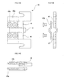
- FIGs. 1A and 1B each show an elevation view and schematic side view of an example of the first aspect of the apparatus for cutting a rubber portion of conveyer belt of the present invention.
- This apparatus for cutting "10" is mainly utilized for splitting the rubber portion of the conveyer belt so as to separate each steel cords embedded in the rubber portion.
- the apparatus for cutting "10” equips the splitting member "4" having the triple blade “3” in which the V-shaped thin blade “2” is disposed within the V-shaped double holder blade "1", "1" so as to protrude from the V-shaped double holder blade.
- the V-shaped thin blade "2" between the V-shaped double holder blade “1", “1” is secured by tightening the V-shaped double holder blade “1", “1” using a plural of screws "5", hence the triple blade "3" are formed as shown in FIG. 2.
- the total included angle ⁇ 1 of the triple blade "3" is preferably within a range of 50° to 70°, and more preferably 60°.
- the blade edge of the V-shaped thin blade “2a” protrudes from the blade edges of the V-shaped double holder blade “1a", “1a” at 3 mm or longer, preferably 5 mm.
- the V-shaped double holder blade "1", “1” is formed of tool steel such as SK, SKS, SKD, SKH or the like, or other sufficiently rigid steel products.
- the V-shaped thin blade "2" has preferably a V-shaped angle ⁇ 2 of 110° to 130°, and more preferably 120°.
- a thin blade having the above-mentioned V-shape angle commercially available, inexpensive, parallelogram blades can be used in combination.
- the triple blade "3" is mounted from both side edges of the double holder blade “1” by the mounting members "6", “6", and secured so that the V-shaped blade part is touched with the rubber portion positioned between each steel cords embedded in the rubber portion of conveyer belt, as shown in FIGs. 1A and 1B.
- the hooks "7", "7” are provided at one end of the mounting members "6", “6”, as shown in FIG. 1B, so as to be able to hang wire, chain or the like thereon, though these are not shown in FIG. 1B.
- the apparatus for cutting "10" equips a plurality of movable rollers "17", “17” positioned between the hooks "7", “7", and the object to be cut (conveyer belt) "8", as shown in FIG. 4.
- the movable rollers "17", “17” are disposed upper side and under side with respect to the object to be cut (conveyer belt) "8” so as to nip the object to be cut (conveyer belt) "8” by the movable rollers "17", "17".
- the apparatus for cutting a rubber portion of conveyer belt of the present invention a ruined blade can easily be replaced hence frequency grinding of blade edge is not required.
- the object to be cut tends not to offset in vertical direction during splitting. Even in the case that the object to be cut offsets, a rubber portion positioned between each steel cords can be split smoothly and steadily.
- the first aspect of the apparatus for cutting is dedicated to use of splitting a rubber portion positioned between each steel cords, thick, strong steel cords do not damage a blade edge, and the steel cords are not damaged by the blade edge, hence the splitting operation can be smoothly carried out.
- FIG. 5 shows an example of a side view of the second aspect of the apparatus for cutting a rubber portion of conveyer belt "20" of the present invention.
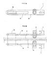
- FIGs. 6A and 6B are enlarged views of the blade part, and
- FIG. 7 is a partial enlarged view of the cylindrical blade "13".
- This apparatus for cutting "20" is mainly utilized for cutting the rubber portion off from the separated steel cords.
- the apparatus for cutting “20” equips the cutting apparatus "14", in which the cylindrical blade "13” is disposed in the double holder "15", "15".
- the straight thin blades "12", “12” are disposed between the semicylinder blades.
- the double holder "15", “15”, is disposed so as to attach to the straight thin blades.
- the cylindrical blade is formed of tool steel such as SK, SKS, SKD, SKH or the like, or other sufficiently rigid steel products.
- the cylindrical blade "13”, which surrounds a steel cord, disposed in the double holder, is secured by tightening the double holder "15", "15” using a plural of screws "5", so that the cylindrical blade is replaceable.
- the included angle ⁇ 3 of the cylindrical blade "13" is preferably within a range of 25° to 35°, and more preferably within a range of 25° to 30°, as shown in FIG. 7.
- the straight thin blades "12", "12” are disposed with an angle so as to gradually retract in the cylindrical blade "13" in the vertical direction and to be replaceable.
- straight thin blades commercially available, inexpensive, parallelogram blades can be used.
- the straight thin blade "12" can be omitted.
- the cutting member "14" is mounted by the mounting members "6", “6” from both side edges of the straight thin blades "12” so that the cylindrical blade "13" surrounds each steel cords, as shown in FIG. 5.
- the hooks "7", "7” are provided at one end of the mounting members "6", “6", and wire, chain or the like can be hanged from the front, though these are not shown in figures.
- the apparatus for cutting "20" equips a plurality of movable rollers "17", “17” positioned between the hooks "7", “7", and the object to be cut (conveyer belt) "8", as shown in FIG. 8.
- the movable rollers "17", “17” are disposed upper side and under side with respect to the object to be cut (conveyer belt) "8” so as to nip the object to be cut (conveyer belt) "8" by the rollers "17", "17".
- non-integral construction of the cylindrical blade, which surrounds a steel cord, and the double holder realize easy maintenance of blades.
- the cutting blade is worn, therefore, only the cylindrical blade can be replaced with a spare blade and then the cutting operation can be continuously carried out.
- the second aspect of the apparatus for cutting is dedicated to use of cutting off a rubber portion from steel cords, thick, strong steel cords do not damage a blade edge, and the steel cords are not damaged by the blade edge, hence the cutting operation can be carried out smoothly.
- arms having rail ways thereon are disposed upper side and under side with respect to a conveyer belt which is an object to be cut, and the splitting member of the first aspect or the cutting member of the second aspects is disposed to the arms.
- the arms "32", “32”, are disposed upper side and under side with respect to the conveyer belt as an object to be cut "8".
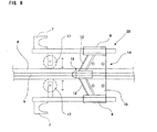
- a plurality of movable rollers "31”, “31” are disposed to the arms “32", “32”, so as to nip the conveyer belt “8" from upper side and under side, and the wedge-shaped cutout portion "33” is also provided to the arms "32", "32", so that the splitting or cutting member "30" can be disposed to the arms.
- a total number of disposed movable roller “31" is two including upper side and under side in FIGs. 9A and 9B, four rollers can also be disposed at upper side and under side.
- the hooks "7", “7”, are disposed at one end of the arms "32", "32", so as to be able to hung a wire, a chain, or the like, though they are not shown in the figure.
- the splitting or cutting member "30" disposed at the wedge-shaped cutout portion "33" is not particularly limited, and can be selected according to the purpose.
- it may suitably be the splitting member "4" of the first aspect, which is dedicated to use of splitting a rubber portion positioned between each steel cords as shown in FIGs. 1A and 1B.
- It may also suitably be the cutting member "14" of the second aspect, which is dedicated to use of cutting a rubber portion off from the steel cords as shown in FIG. 5. Of these two, it is more beneficial to utilize the cutting member "14" in FIG. 5, from the viewpoint being explained hereinafter.
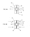
- the double holder "15”, “15”, and the cylindrical blade “13” receive the force in the direction shown with the arrow, by drawbar pull caused from cutting, as shown in FIG. 10B.
- the double holder "15”, “15”, and the cylindrical blade "13" are more tightly fixed and then opening blade edges of the semicylinder blades "11a”, "11a”, can be prevented.
- the cutting member "14" is easily replaced from the arms.
- nipping (sandwiching) an object to be cut by a plural of movable rollers enables the splitting or cutting member to adjust to a sense of the object even which is twisted during cutting, and wear of blade edge can be reduced.
- the apparatus for cutting a rubber portion of conveyer belt of the present invention can suitably be an apparatus in which the splitting members "4" of the first aspect in FIGS. 1A and 1B, and the cutting members "14" of the second aspect in FIG. 5 are alternately disposed.
- both side of cover rubbers of the conveyer belt "8" is partly cut and removed along the steel cords "9", with a width of 200 mm to 250 mm and at a part where close to a terminal of the conveyer belt, by using a knife.
- a bonding rubber portion positioned between the steel cords "9” is split by using a knife or an electric heat cutter so that each steel cords "9” are separated and some bonding rubber portion remains around each steel cords.
- the bonding rubber portion is cut off by using a knife and the steel cords "9” are efficiently strip off as shown in FIG. 10 (pre-treatment).
- At least one of the splitting member "4" of the first aspect in FIGs. 1A and 1B is placed between the stripped steel cords.
- a wire or the like is hanged from each hooks "7", “7” of the splitting member, and at least one of the splitting member "4" is sifted towards a terminal of the conveyer belt in course of winding the wire or the like by a winch or the like (FIG. 12).
- the bonding rubber portion positioned between each steel cords "9” is split so as to separate each steel cords, and the cutting member "14" of the second aspect (not shown in the figure) is individually placed to the bonding rubber portion around the separated steel cord.
- a wire or the like is hanged from each hooks "7", “7” of the cutting member, and at least one of the cutting member "14” is sifted towards a terminal of the conveyer belt in course of winding the wire or the like by a winch or the like. As a result, the bonding rubber portion around the steel cord "9" is cut off.
- the conveyer belt is fixed by clamping using a suitable clamping member.
- a rubber portion of a conveyer belt can sufficiently be split and cut off with a minimum man-hour in course of sifting the apparatus for cutting a rubber portion of conveyer belt once.
- a rubber portion of a conveyer belt can completely cut off related to a diameter of the cylindrical blade and length of the straight blades.
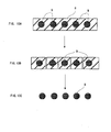
- the conveyer belt "8" in FIG. 13A is split and separated to each steel cords embedded in the rubber portion of the conveyer belt by the apparatus for cutting of the first aspect, as shown in FIG. 13B. Thereafter, the rubber portion remained around the separated steel cord is sufficiently cut off by the apparatus for cutting of the second aspect, as shown in FIG. 13C.
- each steel cords "9” are almost completely and uniformly strip off from the conveyer belt "8" at an entire predetermined length, thus an additional cutting operation to each steel cords "9” can be omitted.
- the method of sifting the apparatus for cutting is not particularly limited to the example shown with the figure.
- Another suitable example may be that a rod is hanged from the hook "7", "7", and driving towards a terminal of the conveyer belt by using a reciprocating member such as a screw mechanism, a gear mechanism or a cylinder.
- the cutting operation of a rubber portion can be carried out, without a pre-treatment, by using a terminal part of the conveyer belt to be joined with the same procedure of the pre-treatment.
- cutting performance is significantly excellent and thin blades can be easily replaced by utilizing commercially available, inexpensive, thin blades. Consequently, even if the blade edge becomes dull, grinding of the blade edge is not necessity.
- utilizing the V-shaped blade prevents an object to cut (conveyer belt) to offset in the vertical direction, hence splitting and cutting can carried out smoothly.
- two semicylinder blades and a double holder form a non-integral construction. Consequently, maintenance of blades is easy.
- the semicylinder blades can be replaced with spare semicylinder blades, without replacing the holder, and then the cutting operation can continuously be carried out.
- the present invention has an effect that cutting resistance is reduced and grinding of blade edge can be omitted even an object is a conveyer belt embedded thick, strong steel cords having a diameter of 9 mm to 13 mm. This is realized by splitting the conveyer belt using vertical cut dedicated blade so as to separate each steel cords, and thereafter a cutting operation, which cut off the rubber portion from the separated steel cords, is carried out.
- nipping by a plurality of movable rollers can adjust a splitting or cutting member to the twisted or curved conveyer belt during splitting or cutting. As a result, wearing of blade edge at an early stage can be reduced.
- the double holder and the blade are fixed more tightly with drawbar pull. Therefore the cutting operation is carried out with a constant results, i.e., uniform diameters of the resulted cylinder forms of the stripped steel cords. Moreover, the cutting member is easily replaced from the apparatus, thus it is very convenient for maintenance.
- the present invention prevents blade edges from chipping or breaking which results from touching with steel cords, and ensures smooth splitting and cutting of a rubber portion. Frequent grinding or replacement of blade, or the like can be omitted and surface strands of each steel cords can be sufficiently protected from damages.
- the present invention provides an apparatus and method for cutting a rubber portion of conveyer belt, which are suitable for cutting a rubber portion positioned between each steel cords embedded in the rubber portion of conveyer belt so as to separate each steel cords, and removing the rubber portion remained around the separated steel cords completely and uniformly from each steel cords at predetermined length.
Landscapes
- Engineering & Computer Science (AREA)
- Mechanical Engineering (AREA)
- Life Sciences & Earth Sciences (AREA)
- Forests & Forestry (AREA)
- Environmental & Geological Engineering (AREA)
- Processing And Handling Of Plastics And Other Materials For Molding In General (AREA)
- Belt Conveyors (AREA)
- Tyre Moulding (AREA)
Abstract
Description
Claims (14)
- An apparatus for cutting a rubber portion of conveyer belt comprising:wherein the apparatus for cutting is used for splitting a rubber portion of a conveyer belt so as to separate each steel cords embedded in the conveyer belt, and cutting the rubber portion off from the separated steel cords so as to strip the steel cords, where the splitting member is used for splitting the rubber portion.a splitting member having a triple blade consisting of a V-shaped thin blade and a V-shaped double holder blade, in which the V-shaped thin blade is disposed within the V-shaped double holder blade so as to protrude from the V-shaped double holder blade,
- An apparatus for cutting a rubber portion of conveyer belt according to Claim 1, wherein a blade edge of the V-shaped thin blade protrudes from a blade edge of the V-shaped double holder blade at 3 mm or longer.
- An apparatus for cutting a rubber portion of conveyer belt according to any one of Claims 1 and 2, wherein the V-shaped thin blade is replaceable from the V-shaped double holder blade.
- An apparatus for cutting a rubber portion of conveyer belt according to any one of Claims 1 to 3, wherein a total included angle of the triple blade is within a range of 50° to 70°.
- An apparatus for cutting a rubber portion of conveyer belt according to any one of Claims 1 to 4, an angle of the V-shaped thin blade is within a range of 110° to 130°.
- An apparatus for cutting a rubber portion of conveyer belt according to any one of Claims 1 to 5, further comprising:a plurality of rollers attached to the splitting member so as to nip the conveyer belt from both upper and under sides and to transport the conveyer belt forwards and backwards.
- An apparatus for cutting a rubber portion of conveyer belt, comprising:wherein the apparatus for cutting is used for splitting a rubber portion of a conveyer belt so as to separate each steel cords embedded in the conveyer belt, and cutting the rubber portion off from the separated steel cords so as to strip the steel cords, where the cutting member is used for cutting the rubber portion off.a cutting member having a cylindrical blade consisting of two straight thin blades and two semicylinder blades, and a double holder, where the straight thin blades are disposed between the semicylinder blades so as to protrude from both side edges of the semicylinder blades, and the double holder is disposed so as to attach to the straight thin blades and to have the cylindrical blade replaceable therefrom,
- An apparatus for cutting a rubber portion of conveyer belt according to Claim 7, wherein blade edges of the semicylinder blades protrude from a blade edge of the straight thin blades.
- An apparatus for cutting a rubber portion of conveyer belt according to any one of Claims 7 and 8, wherein an included angle of the cylindrical blade is 25° to 35°.
- An apparatus for cutting a rubber portion of conveyer belt according to any one of Claims 7 to 9, further comprising:a plurality of rollers attached to the cutting member so as to nip the conveyer belt from both upper and under sides and to transport the conveyer belt forwards and backwards.
- An apparatus for cutting a rubber portion of conveyer belt, comprising:wherein the splitting member and the cutting member are alternately disposed.a plurality of the splitting member as in any one of Claims 1 to 6 for splitting a rubber portion of conveyer belt so as to separate each steel cords embedded in the conveyer belt; anda plurality of the cutting member as in any one of Claims 7 to 10 for cutting the rubber portion off from the separated steel cords,
- An apparatus for cutting a rubber portion of conveyer belt, comprising:wherein the arms have a wedge-shaped cutout portion so as to dispose the splitting member therein.arms having rails thereon and disposed both upper and under sides with respect to a conveyer belt to be cut;a plurality of movable rollers disposed to the arms so as to nip the conveyer belt from both upper and under sides;the splitting member as in any one of Claims 1 to 6 for splitting the conveyer belt so as to separate each steel cords embedded therein,
- An apparatus for cutting a rubber portion of conveyer belt, comprising:wherein the arms have a wedge-shaped cutout portion so as to dispose the cutting member therein.arms having rails thereon and disposed both upper and under sides with respect to a conveyer belt to be cut;a plurality of movable rollers disposed to the arms so as to nip the conveyer belt from both upper and under sides;the cutting member as in any one of Claims 7 to 10 for cutting the rubber portion off from the separated steel cords so as to strip the steel cords,
- A method for cutting a rubber portion of a conveyer belt comprising the steps of:splitting a rubber portion of conveyer belt positioned between each steel cords embedded in the rubber portion of conveyer belt using the splitting member as in any one of Claims 1 to 6, so as to separate the steel cords;cutting the rubber portion off from the separated steel cords using the cutting member as in any one of Claims 7 to 10 so as to strip the steel cords.
Applications Claiming Priority (3)
| Application Number | Priority Date | Filing Date | Title |
|---|---|---|---|
| JP2001049706 | 2001-02-26 | ||
| JP2001049706 | 2001-02-26 | ||
| PCT/JP2002/001612 WO2002068162A1 (en) | 2001-02-26 | 2002-02-22 | Device and method for ripping gum of conveyor belt |
Publications (3)
| Publication Number | Publication Date |
|---|---|
| EP1371463A1 true EP1371463A1 (en) | 2003-12-17 |
| EP1371463A4 EP1371463A4 (en) | 2004-05-06 |
| EP1371463B1 EP1371463B1 (en) | 2007-05-09 |
Family
ID=18910770
Family Applications (1)
| Application Number | Title | Priority Date | Filing Date |
|---|---|---|---|
| EP20020700712 Expired - Lifetime EP1371463B1 (en) | 2001-02-26 | 2002-02-22 | Device and method for ripping gum of conveyor belt |
Country Status (6)
| Country | Link |
|---|---|
| US (2) | US7200939B2 (en) |
| EP (1) | EP1371463B1 (en) |
| JP (1) | JP4166575B2 (en) |
| AU (1) | AU2002233699B2 (en) |
| DE (1) | DE60220033T2 (en) |
| WO (1) | WO2002068162A1 (en) |
Cited By (1)
| Publication number | Priority date | Publication date | Assignee | Title |
|---|---|---|---|---|
| CN102481695A (en) * | 2009-08-25 | 2012-05-30 | 株式会社普利司通 | Device and method for ripping gum of conveyor belt |
Families Citing this family (12)
| Publication number | Priority date | Publication date | Assignee | Title |
|---|---|---|---|---|
| JP2006075951A (en) * | 2004-09-10 | 2006-03-23 | Bridgestone Corp | Cutter for cutting rubber sheet material including cord |
| JP4312224B2 (en) * | 2006-11-07 | 2009-08-12 | 住友ゴム工業株式会社 | Cutting device for ear of raw sheet for tire |
| JP2009184045A (en) * | 2008-02-05 | 2009-08-20 | Fujipura Kk | Film cutting device. |
| KR101286270B1 (en) * | 2011-07-04 | 2013-07-15 | 박병완 | Rubber cutters |
| JP5864752B2 (en) | 2011-08-31 | 2016-02-17 | エーエスエムエル ネザーランズ ビー.ブイ. | Method for determining focus correction, lithographic processing cell and device manufacturing method |
| CN112847666B (en) * | 2021-01-13 | 2022-04-12 | 山东超工激光科技有限公司 | A double-knife cutting machine with inclined cutting |
| CN113199848B (en) * | 2021-04-29 | 2023-03-24 | 南京曼润高分子科技研究院有限公司 | Rubber material cutting device and rubber material cutting method for conveying belt |
| CN115890754B (en) * | 2021-08-20 | 2025-11-11 | 西门子歌美飒再生能源(上海)有限公司 | Cutting device |
| KR102717341B1 (en) * | 2022-05-27 | 2024-10-15 | 주식회사 덕진신소재 | Conveyor Belt Connection Rubber Removal Device |
| CN115042263B (en) * | 2022-06-27 | 2024-11-08 | 太原理工大学 | A method for separating steel wire rope core of conveyor belt |
| KR102855434B1 (en) * | 2023-02-27 | 2025-09-04 | 현대제철 주식회사 | Separating apparatus of steel wire for belt conveyor |
| CN117863271B (en) * | 2024-02-26 | 2026-07-28 | 太原理工大学 | Continuous and rapid separating device for split steel wire rope adhesive tape |
Family Cites Families (17)
| Publication number | Priority date | Publication date | Assignee | Title |
|---|---|---|---|---|
| US1572304A (en) * | 1922-11-24 | 1926-02-09 | Morton William Bunting | Oilcloth fixture |
| US3137192A (en) * | 1962-12-21 | 1964-06-16 | Robert M Mcneill | Material cutting device |
| CH587106A5 (en) * | 1973-10-12 | 1977-04-29 | Granger Maurice | |
| US4435555A (en) * | 1981-07-20 | 1984-03-06 | American Cyanamid Company | Novel polymeric light stabilizers for polymers |
| JPS6254696A (en) * | 1985-08-29 | 1987-03-10 | 豊田合成株式会社 | Cutting tool for cutting resin molded-shape gate solidified body |
| JPH07106552B2 (en) * | 1987-04-24 | 1995-11-15 | 株式会社ブリヂストン | Conveyor belt rubber cutting device |
| JPH0231694A (en) | 1988-04-08 | 1990-02-01 | Idemitsu Kosan Co Ltd | Preparation of optically active alpha-amino acid and/or alpha-amino amide |
| JPH0231694U (en) * | 1988-08-23 | 1990-02-28 | ||
| US4920644A (en) * | 1989-03-30 | 1990-05-01 | Lagattuta Milton | Disposable straight razor and/or blade holder therefor |
| DD301717A7 (en) * | 1989-06-12 | 1993-08-12 | Lausitzer Braunkohle Ag | Device for peeling off the cover layer of conveyor belts |
| US5085114A (en) * | 1990-09-04 | 1992-02-04 | Molex Incorporated | Method for facilitating removal of insulation from wires |
| US5256496A (en) * | 1991-11-15 | 1993-10-26 | Kluczynski Mathew L | Titanium-steel laminate knife |
| DE4409438C1 (en) * | 1994-03-19 | 1995-07-20 | Peter Dipl Ing Ladwig | Appts. for disposal of cladded pipes |
| DE69725281T2 (en) * | 1996-07-11 | 2004-08-12 | Japan Tobacco Inc. | Device and cutting knife for cutting a compression molded article from sheet materials |
| US5967012A (en) * | 1996-11-19 | 1999-10-19 | The United States Of America As Represented By The Secretary Of The Navy | Waste aerosol container processor |
| JP4011776B2 (en) * | 1999-02-05 | 2007-11-21 | バンドー化学株式会社 | Method and apparatus for processing used ST conveyor belt |
| RO116890B1 (en) * | 1999-12-06 | 2001-07-30 | Sc Artego Sa | Process and installation for recovering rubber and steel cord from worn conveyer belts |
-
2002
- 2002-02-22 DE DE2002620033 patent/DE60220033T2/en not_active Expired - Lifetime
- 2002-02-22 WO PCT/JP2002/001612 patent/WO2002068162A1/en not_active Ceased
- 2002-02-22 JP JP2002567507A patent/JP4166575B2/en not_active Expired - Fee Related
- 2002-02-22 EP EP20020700712 patent/EP1371463B1/en not_active Expired - Lifetime
- 2002-02-22 AU AU2002233699A patent/AU2002233699B2/en not_active Ceased
- 2002-02-22 US US10/469,187 patent/US7200939B2/en not_active Expired - Lifetime
-
2007
- 2007-02-13 US US12/229,495 patent/US8127456B2/en not_active Expired - Fee Related
Cited By (1)
| Publication number | Priority date | Publication date | Assignee | Title |
|---|---|---|---|---|
| CN102481695A (en) * | 2009-08-25 | 2012-05-30 | 株式会社普利司通 | Device and method for ripping gum of conveyor belt |
Also Published As
| Publication number | Publication date |
|---|---|
| DE60220033D1 (en) | 2007-06-21 |
| US7200939B2 (en) | 2007-04-10 |
| US8127456B2 (en) | 2012-03-06 |
| JPWO2002068162A1 (en) | 2004-06-24 |
| US20040079209A1 (en) | 2004-04-29 |
| EP1371463A4 (en) | 2004-05-06 |
| EP1371463B1 (en) | 2007-05-09 |
| WO2002068162A1 (en) | 2002-09-06 |
| AU2002233699B2 (en) | 2008-01-10 |
| JP4166575B2 (en) | 2008-10-15 |
| DE60220033T2 (en) | 2008-01-10 |
| US20090013539A1 (en) | 2009-01-15 |
Similar Documents
| Publication | Publication Date | Title |
|---|---|---|
| US8127456B2 (en) | Apparatus and method for cutting rubber portion of conveyer belt | |
| JP5455207B2 (en) | Rubber cutting device for conveyor belt and rubber cutting method | |
| US12409576B2 (en) | Knife assembly and cutting system equipped with same | |
| US5476417A (en) | Bent blade holder apparatus and method | |
| EP0105552B1 (en) | Method and machine for removing at least one layer of reinforcing elements from a breaker or belt of a rubber tyre | |
| US6439084B1 (en) | Laminated blade assembly for cutting insulation | |
| US5938518A (en) | Method for separating a superficial layer and apparatus for carrying out the method | |
| US5152206A (en) | Vinyl trim salvage machine | |
| JPH07106552B2 (en) | Conveyor belt rubber cutting device | |
| JP2021531985A (en) | Methods for stabilizing cross-cut devices and squeeze cuts | |
| EP2815653B1 (en) | Device for removing skin of meat cuts of irregular thickness | |
| CN216176227U (en) | Shearing mechanism is used in processing of U type silk | |
| EP1098753A1 (en) | Method and apparatus for cutting tire ply stock | |
| CN217115411U (en) | Pneumatic peeling machine for cable | |
| EP0867118B1 (en) | Spinal column separation | |
| JP2001100047A (en) | Method for finishing a cable end face and apparatus for carrying out the method | |
| WO1994017670A1 (en) | Device for cutting fish | |
| KR102104787B1 (en) | Router set | |
| RU2314913C1 (en) | Tire casings cutting device | |
| IES991004A2 (en) | Defatting of meat cuts | |
| CN115847499A (en) | Blade subassembly of peeler | |
| IE83393B1 (en) | Defatting of meat cuts | |
| IE991003A1 (en) | Defatting of meat cuts | |
| JPH0739217U (en) | Electric wire end processing device cutter | |
| JPH0548517U (en) | Cable end processing jig |
Legal Events
| Date | Code | Title | Description |
|---|---|---|---|
| PUAI | Public reference made under article 153(3) epc to a published international application that has entered the european phase |
Free format text: ORIGINAL CODE: 0009012 |
|
| 17P | Request for examination filed |
Effective date: 20030918 |
|
| AK | Designated contracting states |
Kind code of ref document: A1 Designated state(s): AT BE CH CY DE DK ES FI FR GB GR IE IT LI LU MC NL PT SE TR |
|
| AX | Request for extension of the european patent |
Extension state: AL LT LV MK RO SI |
|
| A4 | Supplementary search report drawn up and despatched |
Effective date: 20040319 |
|
| RIC1 | Information provided on ipc code assigned before grant |
Ipc: 7B 26D 1/00 B Ipc: 7B 26D 1/03 B Ipc: 7B 26D 1/02 B Ipc: 7B 26D 3/28 B Ipc: 7B 26D 1/04 B Ipc: 7B 26F 3/00 A |
|
| 17Q | First examination report despatched |
Effective date: 20040806 |
|
| GRAP | Despatch of communication of intention to grant a patent |
Free format text: ORIGINAL CODE: EPIDOSNIGR1 |
|
| GRAS | Grant fee paid |
Free format text: ORIGINAL CODE: EPIDOSNIGR3 |
|
| GRAA | (expected) grant |
Free format text: ORIGINAL CODE: 0009210 |
|
| AK | Designated contracting states |
Kind code of ref document: B1 Designated state(s): DE |
|
| REF | Corresponds to: |
Ref document number: 60220033 Country of ref document: DE Date of ref document: 20070621 Kind code of ref document: P |
|
| PLBE | No opposition filed within time limit |
Free format text: ORIGINAL CODE: 0009261 |
|
| STAA | Information on the status of an ep patent application or granted ep patent |
Free format text: STATUS: NO OPPOSITION FILED WITHIN TIME LIMIT |
|
| 26N | No opposition filed |
Effective date: 20080212 |
|
| PGFP | Annual fee paid to national office [announced via postgrant information from national office to epo] |
Ref country code: DE Payment date: 20120215 Year of fee payment: 11 |
|
| REG | Reference to a national code |
Ref country code: DE Ref legal event code: R119 Ref document number: 60220033 Country of ref document: DE Effective date: 20130903 |
|
| PG25 | Lapsed in a contracting state [announced via postgrant information from national office to epo] |
Ref country code: DE Free format text: LAPSE BECAUSE OF NON-PAYMENT OF DUE FEES Effective date: 20130903 |