EP1371439A1 - Method of weld repairing a component with a refractory metal backing material - Google Patents
Method of weld repairing a component with a refractory metal backing material Download PDFInfo
- Publication number
- EP1371439A1 EP1371439A1 EP03253664A EP03253664A EP1371439A1 EP 1371439 A1 EP1371439 A1 EP 1371439A1 EP 03253664 A EP03253664 A EP 03253664A EP 03253664 A EP03253664 A EP 03253664A EP 1371439 A1 EP1371439 A1 EP 1371439A1
- Authority
- EP
- European Patent Office
- Prior art keywords
- metal material
- refractory metal
- over
- piece
- placing
- Prior art date
- Legal status (The legal status is an assumption and is not a legal conclusion. Google has not performed a legal analysis and makes no representation as to the accuracy of the status listed.)
- Granted
Links
Images
Classifications
-
- B—PERFORMING OPERATIONS; TRANSPORTING
- B23—MACHINE TOOLS; METAL-WORKING NOT OTHERWISE PROVIDED FOR
- B23P—METAL-WORKING NOT OTHERWISE PROVIDED FOR; COMBINED OPERATIONS; UNIVERSAL MACHINE TOOLS
- B23P6/00—Restoring or reconditioning objects
- B23P6/002—Repairing turbine components, e.g. moving or stationary blades, rotors
- B23P6/007—Repairing turbine components, e.g. moving or stationary blades, rotors using only additive methods, e.g. build-up welding
-
- B—PERFORMING OPERATIONS; TRANSPORTING
- B23—MACHINE TOOLS; METAL-WORKING NOT OTHERWISE PROVIDED FOR
- B23K—SOLDERING OR UNSOLDERING; WELDING; CLADDING OR PLATING BY SOLDERING OR WELDING; CUTTING BY APPLYING HEAT LOCALLY, e.g. FLAME CUTTING; WORKING BY LASER BEAM
- B23K37/00—Auxiliary devices or processes, not specially adapted for a procedure covered by only one of the other main groups of this subclass
- B23K37/04—Auxiliary devices or processes, not specially adapted for a procedure covered by only one of the other main groups of this subclass for holding or positioning work
-
- B—PERFORMING OPERATIONS; TRANSPORTING
- B23—MACHINE TOOLS; METAL-WORKING NOT OTHERWISE PROVIDED FOR
- B23K—SOLDERING OR UNSOLDERING; WELDING; CLADDING OR PLATING BY SOLDERING OR WELDING; CUTTING BY APPLYING HEAT LOCALLY, e.g. FLAME CUTTING; WORKING BY LASER BEAM
- B23K10/00—Welding or cutting by means of a plasma
- B23K10/02—Plasma welding
- B23K10/027—Welding for purposes other than joining, e.g. build-up welding
-
- B—PERFORMING OPERATIONS; TRANSPORTING
- B23—MACHINE TOOLS; METAL-WORKING NOT OTHERWISE PROVIDED FOR
- B23K—SOLDERING OR UNSOLDERING; WELDING; CLADDING OR PLATING BY SOLDERING OR WELDING; CUTTING BY APPLYING HEAT LOCALLY, e.g. FLAME CUTTING; WORKING BY LASER BEAM
- B23K26/00—Working by laser beam, e.g. welding, cutting or boring
- B23K26/20—Bonding
- B23K26/32—Bonding taking account of the properties of the material involved
-
- B—PERFORMING OPERATIONS; TRANSPORTING
- B23—MACHINE TOOLS; METAL-WORKING NOT OTHERWISE PROVIDED FOR
- B23K—SOLDERING OR UNSOLDERING; WELDING; CLADDING OR PLATING BY SOLDERING OR WELDING; CUTTING BY APPLYING HEAT LOCALLY, e.g. FLAME CUTTING; WORKING BY LASER BEAM
- B23K26/00—Working by laser beam, e.g. welding, cutting or boring
- B23K26/34—Laser welding for purposes other than joining
- B23K26/342—Build-up welding
-
- B—PERFORMING OPERATIONS; TRANSPORTING
- B23—MACHINE TOOLS; METAL-WORKING NOT OTHERWISE PROVIDED FOR
- B23K—SOLDERING OR UNSOLDERING; WELDING; CLADDING OR PLATING BY SOLDERING OR WELDING; CUTTING BY APPLYING HEAT LOCALLY, e.g. FLAME CUTTING; WORKING BY LASER BEAM
- B23K35/00—Rods, electrodes, materials, or media, for use in soldering, welding, or cutting
- B23K35/22—Rods, electrodes, materials, or media, for use in soldering, welding, or cutting characterised by the composition or nature of the material
- B23K35/24—Selection of soldering or welding materials proper
- B23K35/30—Selection of soldering or welding materials proper with the principal constituent melting at less than 1550°C
- B23K35/3033—Ni as the principal constituent
-
- B—PERFORMING OPERATIONS; TRANSPORTING
- B23—MACHINE TOOLS; METAL-WORKING NOT OTHERWISE PROVIDED FOR
- B23K—SOLDERING OR UNSOLDERING; WELDING; CLADDING OR PLATING BY SOLDERING OR WELDING; CUTTING BY APPLYING HEAT LOCALLY, e.g. FLAME CUTTING; WORKING BY LASER BEAM
- B23K35/00—Rods, electrodes, materials, or media, for use in soldering, welding, or cutting
- B23K35/22—Rods, electrodes, materials, or media, for use in soldering, welding, or cutting characterised by the composition or nature of the material
- B23K35/24—Selection of soldering or welding materials proper
- B23K35/30—Selection of soldering or welding materials proper with the principal constituent melting at less than 1550°C
- B23K35/3046—Co as the principal constituent
-
- B—PERFORMING OPERATIONS; TRANSPORTING
- B23—MACHINE TOOLS; METAL-WORKING NOT OTHERWISE PROVIDED FOR
- B23K—SOLDERING OR UNSOLDERING; WELDING; CLADDING OR PLATING BY SOLDERING OR WELDING; CUTTING BY APPLYING HEAT LOCALLY, e.g. FLAME CUTTING; WORKING BY LASER BEAM
- B23K35/00—Rods, electrodes, materials, or media, for use in soldering, welding, or cutting
- B23K35/22—Rods, electrodes, materials, or media, for use in soldering, welding, or cutting characterised by the composition or nature of the material
- B23K35/24—Selection of soldering or welding materials proper
- B23K35/32—Selection of soldering or welding materials proper with the principal constituent melting at more than 1550°C
- B23K35/327—Selection of soldering or welding materials proper with the principal constituent melting at more than 1550°C comprising refractory compounds, e.g. carbides
-
- B—PERFORMING OPERATIONS; TRANSPORTING
- B23—MACHINE TOOLS; METAL-WORKING NOT OTHERWISE PROVIDED FOR
- B23K—SOLDERING OR UNSOLDERING; WELDING; CLADDING OR PLATING BY SOLDERING OR WELDING; CUTTING BY APPLYING HEAT LOCALLY, e.g. FLAME CUTTING; WORKING BY LASER BEAM
- B23K37/00—Auxiliary devices or processes, not specially adapted for a procedure covered by only one of the other main groups of this subclass
- B23K37/06—Auxiliary devices or processes, not specially adapted for a procedure covered by only one of the other main groups of this subclass for positioning the molten material, e.g. confining it to a desired area
-
- B—PERFORMING OPERATIONS; TRANSPORTING
- B23—MACHINE TOOLS; METAL-WORKING NOT OTHERWISE PROVIDED FOR
- B23K—SOLDERING OR UNSOLDERING; WELDING; CLADDING OR PLATING BY SOLDERING OR WELDING; CUTTING BY APPLYING HEAT LOCALLY, e.g. FLAME CUTTING; WORKING BY LASER BEAM
- B23K9/00—Arc welding or cutting
- B23K9/04—Welding for other purposes than joining, e.g. built-up welding
- B23K9/044—Built-up welding on three-dimensional surfaces
-
- F—MECHANICAL ENGINEERING; LIGHTING; HEATING; WEAPONS; BLASTING
- F01—MACHINES OR ENGINES IN GENERAL; ENGINE PLANTS IN GENERAL; STEAM ENGINES
- F01D—NON-POSITIVE DISPLACEMENT MACHINES OR ENGINES, e.g. STEAM TURBINES
- F01D5/00—Blades; Blade-carrying members; Heating, heat-insulating, cooling or antivibration means on the blades or the members
- F01D5/005—Repairing methods or devices
-
- B—PERFORMING OPERATIONS; TRANSPORTING
- B23—MACHINE TOOLS; METAL-WORKING NOT OTHERWISE PROVIDED FOR
- B23K—SOLDERING OR UNSOLDERING; WELDING; CLADDING OR PLATING BY SOLDERING OR WELDING; CUTTING BY APPLYING HEAT LOCALLY, e.g. FLAME CUTTING; WORKING BY LASER BEAM
- B23K2101/00—Articles made by soldering, welding or cutting
- B23K2101/001—Turbines
-
- B—PERFORMING OPERATIONS; TRANSPORTING
- B23—MACHINE TOOLS; METAL-WORKING NOT OTHERWISE PROVIDED FOR
- B23K—SOLDERING OR UNSOLDERING; WELDING; CLADDING OR PLATING BY SOLDERING OR WELDING; CUTTING BY APPLYING HEAT LOCALLY, e.g. FLAME CUTTING; WORKING BY LASER BEAM
- B23K2101/00—Articles made by soldering, welding or cutting
- B23K2101/34—Coated articles ; Surface treated articles
-
- B—PERFORMING OPERATIONS; TRANSPORTING
- B23—MACHINE TOOLS; METAL-WORKING NOT OTHERWISE PROVIDED FOR
- B23K—SOLDERING OR UNSOLDERING; WELDING; CLADDING OR PLATING BY SOLDERING OR WELDING; CUTTING BY APPLYING HEAT LOCALLY, e.g. FLAME CUTTING; WORKING BY LASER BEAM
- B23K2103/00—Materials to be soldered, welded or cut
- B23K2103/08—Non-ferrous metals or alloys
-
- B—PERFORMING OPERATIONS; TRANSPORTING
- B23—MACHINE TOOLS; METAL-WORKING NOT OTHERWISE PROVIDED FOR
- B23K—SOLDERING OR UNSOLDERING; WELDING; CLADDING OR PLATING BY SOLDERING OR WELDING; CUTTING BY APPLYING HEAT LOCALLY, e.g. FLAME CUTTING; WORKING BY LASER BEAM
- B23K2103/00—Materials to be soldered, welded or cut
- B23K2103/18—Dissimilar materials
-
- B—PERFORMING OPERATIONS; TRANSPORTING
- B23—MACHINE TOOLS; METAL-WORKING NOT OTHERWISE PROVIDED FOR
- B23K—SOLDERING OR UNSOLDERING; WELDING; CLADDING OR PLATING BY SOLDERING OR WELDING; CUTTING BY APPLYING HEAT LOCALLY, e.g. FLAME CUTTING; WORKING BY LASER BEAM
- B23K2103/00—Materials to be soldered, welded or cut
- B23K2103/18—Dissimilar materials
- B23K2103/26—Alloys of Nickel and Cobalt and Chromium
-
- Y—GENERAL TAGGING OF NEW TECHNOLOGICAL DEVELOPMENTS; GENERAL TAGGING OF CROSS-SECTIONAL TECHNOLOGIES SPANNING OVER SEVERAL SECTIONS OF THE IPC; TECHNICAL SUBJECTS COVERED BY FORMER USPC CROSS-REFERENCE ART COLLECTIONS [XRACs] AND DIGESTS
- Y10—TECHNICAL SUBJECTS COVERED BY FORMER USPC
- Y10T—TECHNICAL SUBJECTS COVERED BY FORMER US CLASSIFICATION
- Y10T29/00—Metal working
- Y10T29/49—Method of mechanical manufacture
- Y10T29/49316—Impeller making
- Y10T29/49318—Repairing or disassembling
Definitions
- the present invention relates to a method for repairing a component, such as a turbine blade or a vane, used in a gas turbine engine.
- gas turbine blade tips and trailing edge regions are repaired using a welding process such as gas tungsten arc welding without a backing material.
- the weld bead is used to build up cracked and worn surfaces. Problems occur when blade tip cracks expose blade internal cavities. In this case, the weld will flow into the cavity and result in a rejectable condition. In other areas, such as a blade trailing edge, weld repair will result in closure of the internal cooling features that will then need to be re-established by labor intensive blending or electrodischarge machining.
- a method for repairing a component used in a turbine engine broadly comprises the steps of placing a piece of refractory metal material over an area of the component to be repaired and depositing a repair filler metal material over the piece of refractory metal material in an amount sufficient to repair the component and welding same.
- the refractory metal material may be any refractory material having a melting point in excess of 1455°C (2651°F) and may be coated or uncoated.
- a method for repairing a turbine engine component, such as a turbine blade or vane, formed from a superalloy material, such as a nickel-based or cobalt-based alloy, and used in a gas turbine engine.
- the method broadly comprises placing a piece of refractory metal material over the area of the component to be repaired and depositing a repair filler metal material over the refractory metal material in an amount sufficient to fill in the space being repaired and welding same.
- the refractory metal material acts as a backing material for preventing the repair filler metal material from entering internal cavities such as internal cooling cavities.
- a tip 10 of a turbine blade to be repaired is illustrated.
- the blade tip 10 has an area 12 to be repaired.
- the blade tip 10 has an open internal cooling cavity 14 in the area to be repaired.
- a piece 16 of backing material formed from a refractory metal material is positioned over the area to be repaired to prevent the entry of the repair material into the cavity 14.
- the refractory metal material preferably has a melting point in excess of 1455°C (2651°F) and most preferably a melting point in excess of 1650°C (3000°F).
- Suitable refractory metals for the backing material 16 include, niobium, tantalum, molybdenum, tungsten, metals having a melting point higher than the melting point of nickel, such as platinum, iridium, and the like, and their alloys.
- the refractory metal backing material 16 may be uncoated or coated. If heat input of the repair is high, a diffusion barrier coating can be applied to the refractory material.
- Candidates include, but are not limited to, oxide ceramics such as alumina or mullite. If an oxide ceramic coating is used, an intermediate coating layer such as a silicide may be used to help coating adherence. When coated with ceramic, it is preferred to nickel plate over the alumina or mullite to aid in wetting the repair filler metal.
- the coating system may also include a nickel aluminide layer left behind after repair to improve the oxidation resistance of the coating.
- the refractory metal backing material may just be nickel plated using electrolytic nickel on at least one side if heat input is low. As previously mentioned, the presence of the coating enhances the wettability of the backing material during the subsequent welding process.
- a repair filler metal material 20 is deposited over the backing material 16 and subjected to a welding operation.
- the repair filler metal material is preferably deposited in an amount sufficient to fill the area 12 to be repaired.
- the repair filler metal material may comprise a cobalt based material, such as MERL 72, or a nickel based material, such as INCO 625.
- the repair filler metal may be a filler metal of the base alloy composition.
- the repair filler metal material may be applied using any suitable welding technique known in the art such as a TIG repair welding technique. During the welding step, the heat input may be kept low to prevent alloying.
- the refractory metal backing material 16 may be removed by an acid chemical treatment using a nitric acid-sulfuric acid solution.
- the solution may have 2 parts nitric acid and 1 part sulfuric acid added to 2 parts water.
- the mixture is preferably heated to a temperature up to 65°C (150°F) to increase the dissolution rate.
- the refractory metal backing material 16 may be removed using an oxidizing heat treatment in which air is flowed through the interior of the blade.
- the flowing air may be at a temperature in the range of 760°C (1400°F) to 900°C (1650°F) and may be flowed through the blade interior for a time in the range of from 1 to 4 hours.
- the oxidizing heat treatment may be performed either in a furnace or by direct resistant heating.
- the removal of the refractory metal backing material may be omitted if the alloying of the refractory metal with filler material is controlled.
- a method for repairing a trailing edge 30 of a turbine blade is illustrated.
- a piece 32 of refractory metal backing material is first cut to conform to the shape of the blade trailing edge and any internal cooling cavity therein.
- Any suitable cutting technique known in the art such as laser cutting, photo etching, stamping, or water jet cutting may be used to cut the refractory metal backing material.
- the refractory metal material may be one of the materials mentioned hereinabove and may be coated or uncoated as discussed above.
- the piece 32 of refractory metal backing material preferably in foil form, is placed over the area 34 to be repaired.
- a repair filler metal material is then deposited over the piece of refractory material 32 and subjected to a welding treatment to re-establish the blade trailing edge including its cooling features 36.
- the refractory metal backing material may be removed using either an acid chemical treatment, such as that described above, or an oxidizing heat treatment, such as that described above.
- the present invention is advantageous in that it allows a refractory metal material to act as a weld backing material to allow welding over open cavities or to re-establish internal cooling geometry.
- the refractory metal material can later be removed if desired without the need for extensive post welding blend processing or machining such as EDM machining. This method has particular utility in the repair of investment castings.
Landscapes
- Engineering & Computer Science (AREA)
- Mechanical Engineering (AREA)
- Physics & Mathematics (AREA)
- Optics & Photonics (AREA)
- Plasma & Fusion (AREA)
- General Engineering & Computer Science (AREA)
- Turbine Rotor Nozzle Sealing (AREA)
- Other Surface Treatments For Metallic Materials (AREA)
- Coating By Spraying Or Casting (AREA)
- Arc Welding In General (AREA)
Abstract
Description
- The present invention relates to a method for repairing a component, such as a turbine blade or a vane, used in a gas turbine engine.
- Currently, gas turbine blade tips and trailing edge regions are repaired using a welding process such as gas tungsten arc welding without a backing material. The weld bead is used to build up cracked and worn surfaces. Problems occur when blade tip cracks expose blade internal cavities. In this case, the weld will flow into the cavity and result in a rejectable condition. In other areas, such as a blade trailing edge, weld repair will result in closure of the internal cooling features that will then need to be re-established by labor intensive blending or electrodischarge machining.
- Accordingly, it is an object of the present invention in a preferred embodiment at least to provide an improved method for repairing turbine engine components.
- It is a further object of the present invention in a preferred embodiment at least to provide a method as above which allows welding over open cavities and which does not require extensive post welding blend processing or machining.
- It is yet another object of the present invention in a preferred embodiment at least to provide a method as above which allows re-establishment of internal cooling geometry.
- In accordance with the present invention, a method for repairing a component used in a turbine engine broadly comprises the steps of placing a piece of refractory metal material over an area of the component to be repaired and depositing a repair filler metal material over the piece of refractory metal material in an amount sufficient to repair the component and welding same. The refractory metal material may be any refractory material having a melting point in excess of 1455°C (2651°F) and may be coated or uncoated.
- Other details of the repair method of the present invention, as well as other advantages attendant thereto, are set forth in the following detailed description and the accompanying drawings wherein like reference numerals depict like elements.
-
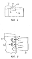
- FIG. 1 illustrates a tip of a turbine engine blade repaired in accordance with the present invention; and
- FIG. 2 illustrates a technique for repairing a trailing edge portion of a turbine engine blade.
-
- In accordance with the present invention, a method is provided for repairing a turbine engine component, such as a turbine blade or vane, formed from a superalloy material, such as a nickel-based or cobalt-based alloy, and used in a gas turbine engine. The method broadly comprises placing a piece of refractory metal material over the area of the component to be repaired and depositing a repair filler metal material over the refractory metal material in an amount sufficient to fill in the space being repaired and welding same. The refractory metal material acts as a backing material for preventing the repair filler metal material from entering internal cavities such as internal cooling cavities.
- Referring now to FIG. 1, a
tip 10 of a turbine blade to be repaired is illustrated. Theblade tip 10 has anarea 12 to be repaired. Theblade tip 10 has an openinternal cooling cavity 14 in the area to be repaired. In such a circumstance, it is necessary that theinternal cooling cavity 14 be protected from the introduction of the repair material. To this end, apiece 16 of backing material formed from a refractory metal material is positioned over the area to be repaired to prevent the entry of the repair material into thecavity 14. The refractory metal material preferably has a melting point in excess of 1455°C (2651°F) and most preferably a melting point in excess of 1650°C (3000°F). Suitable refractory metals for thebacking material 16 include, niobium, tantalum, molybdenum, tungsten, metals having a melting point higher than the melting point of nickel, such as platinum, iridium, and the like, and their alloys. - The refractory
metal backing material 16 may be uncoated or coated. If heat input of the repair is high, a diffusion barrier coating can be applied to the refractory material. Candidates include, but are not limited to, oxide ceramics such as alumina or mullite. If an oxide ceramic coating is used, an intermediate coating layer such as a silicide may be used to help coating adherence. When coated with ceramic, it is preferred to nickel plate over the alumina or mullite to aid in wetting the repair filler metal. The coating system may also include a nickel aluminide layer left behind after repair to improve the oxidation resistance of the coating. Alternatively, the refractory metal backing material may just be nickel plated using electrolytic nickel on at least one side if heat input is low. As previously mentioned, the presence of the coating enhances the wettability of the backing material during the subsequent welding process. - After the refractory
metal backing material 16 has been positioned in thearea 12, a repairfiller metal material 20 is deposited over thebacking material 16 and subjected to a welding operation. The repair filler metal material is preferably deposited in an amount sufficient to fill thearea 12 to be repaired. The repair filler metal material may comprise a cobalt based material, such as MERL 72, or a nickel based material, such as INCO 625. Alternatively, the repair filler metal may be a filler metal of the base alloy composition. The repair filler metal material may be applied using any suitable welding technique known in the art such as a TIG repair welding technique. During the welding step, the heat input may be kept low to prevent alloying. - Once the repair
filler metal material 20 has solidified, the refractorymetal backing material 16 may be removed by an acid chemical treatment using a nitric acid-sulfuric acid solution. The solution may have 2 parts nitric acid and 1 part sulfuric acid added to 2 parts water. The mixture is preferably heated to a temperature up to 65°C (150°F) to increase the dissolution rate. - Alternatively, the refractory
metal backing material 16 may be removed using an oxidizing heat treatment in which air is flowed through the interior of the blade. The flowing air may be at a temperature in the range of 760°C (1400°F) to 900°C (1650°F) and may be flowed through the blade interior for a time in the range of from 1 to 4 hours. The oxidizing heat treatment may be performed either in a furnace or by direct resistant heating. - The removal of the refractory metal backing material may be omitted if the alloying of the refractory metal with filler material is controlled.
- Referring now to FIG. 2, a method for repairing a
trailing edge 30 of a turbine blade is illustrated. In this method, apiece 32 of refractory metal backing material is first cut to conform to the shape of the blade trailing edge and any internal cooling cavity therein. Any suitable cutting technique known in the art such as laser cutting, photo etching, stamping, or water jet cutting may be used to cut the refractory metal backing material. The refractory metal material may be one of the materials mentioned hereinabove and may be coated or uncoated as discussed above. Thepiece 32 of refractory metal backing material, preferably in foil form, is placed over thearea 34 to be repaired. A repair filler metal material is then deposited over the piece ofrefractory material 32 and subjected to a welding treatment to re-establish the blade trailing edge including itscooling features 36. - After the repair filler metal material has solidified, the refractory metal backing material may be removed using either an acid chemical treatment, such as that described above, or an oxidizing heat treatment, such as that described above.
- The present invention is advantageous in that it allows a refractory metal material to act as a weld backing material to allow welding over open cavities or to re-establish internal cooling geometry. The refractory metal material can later be removed if desired without the need for extensive post welding blend processing or machining such as EDM machining. This method has particular utility in the repair of investment castings.
- It is apparent that there has been provided a method for repairing turbine blades which fully satisfies the objects, means and advantages set forth hereinbefore. While the present invention has been described in the context of specific embodiments thereof, other alternatives, modifications, and variations will become apparent to those skilled in the art having read the foregoing description. Accordingly, it is intended to embrace those alternatives, modifications, and variations as fall within the broad scope of the appended claims.
Claims (29)
- A method for repairing a component comprising the steps of:placing a piece of refractory metal material (16;32) over an area (12;34) of said component to be repaired; anddepositing a repair filler metal material (20) over said piece of refractory metal material (12;34) in an amount sufficient to repair said component and subjecting said repair filler metal material to a welding treatment.
- A method according to claim 1, wherein said placing step comprises placing a piece of material (16;32) formed from a material selected from the group consisting of niobium, tantalum, molybdenum, tungsten, a metal having a melting point higher than the melting point of nickel, and alloys thereof over said area.
- A method according to claim 1 or 2, wherein said placing step comprises placing a piece of refractory metal material (16;32) having a nickel plating on at least one surface over said area.
- A method according to claim 1 or 2, wherein said placing step comprises placing a piece of refractory metal material (16;32) having a chromium coating on at least one surface over said area.
- A method according to claim 1 or 2, wherein said placing step comprises placing a piece of refractory metal material (16;32), having a diffusion barrier coating.
- A method according to claim 5, wherein said placing step comprises placing a piece of refractory metal material (16;32) having a coating comprising an alumina or mullite coating.
- A method according to claim 5, wherein said placing step comprises placing a piece of refractory metal material (16;32) having an alumina or mullite coating layer and an intermediate silicide layer.
- A method according to claim 7, wherein said refractory metal material (16;32) further has a nickel plating over said outer layer.
- A method according to any preceding claim, wherein said placing step comprises placing a piece of refractory metal material (16;32) having a melting point in excess of 1455°C over said area.
- A method according to claim 9, wherein said refractory metal material (16;32) has a melting point in excess of 1650°C.
- A method according to any preceding claim, wherein said component comprises a component for a turbine engine having an internal cooling cavity (14) and said placing step comprises positioning said refractory metal material (16) so as to prevent said repair filler metal material (12) from entering said internal cooling cavity (14).
- A method according to any preceding claim, wherein said refractory metal material (16) is a cut foil which conforms to a shape of an internal cooling cavity (14) in said component.
- A method according to any preceding claim, further comprising removing said refractory metal material (16;32) after said welding step has been completed using an acid chemical treatment.
- A method according to any of claims 1-12, further comprising removing said refractory metal material (16;32) after said welding step has been completed using an oxidizing heat treatment.
- A method according to any preceding claim, wherein said placing step comprises placing said piece of refractory metal material (16;32) over an area of an investment cast compact to be repaired.
- A method for repairing a tip portion (10) of a turbine blade comprising the steps of:positioning a refractory metal backing material (16) over an area to be repaired (12); anddepositing a repair filler metal material (20) over said refractory material and welding said repair filler metal material.
- A method according to claim 16, wherein said positioning step comprises positioning a piece of refractory metal material (16) selected from the group consisting of niobium, tantalum, molybdenum, tungsten, a metal having a melting point higher than the melting point of nickel, and alloys thereof over said area to be repaired (12).
- A method according to claim 16 or 17, wherein said positioning step comprises positioning a piece of refractory metal material (1A) plated with a nickel containing material over said area to be repaired (12).
- A method according to claim 16 or 17, wherein said positioning step comprises positioning a piece of refractory metal material (16) coated with a chromium containing material over said area to be repaired (12).
- A method according to claim 16 or 17, wherein said positioning step comprises positioning a piece of refractory metal material (16) having an oxide ceramic coating layer, an intermediate layer of silicide, and a plated nickel outer layer over said area to be repaired (12).
- A method according to any of claims 16 to 20, further comprising removing said refractory metal material (16) after said welding step has been completed using an acid chemical treatment.
- A method according to any of claims 16 to 20, further comprising removing said refractory metal material (16) after said welding step has been completed using an oxidizing heat treatment.
- A method for repairing a trailing edge (30) of a turbine blade comprising:cutting a refractory metal material foil (32) to conform to a trailing edge shape of said blade;positioning said cut refractory metal material foil (32) over a portion (34) of said trailing edge to be repaired; andapplying a repair filler metal material over said refractory metal material foil (32) and welding said repair filler metal material to effect said repair.
- A method according to claim 23, wherein said cutting step comprises cutting a foil material (32) formed from a refractory metal selected from the group consisting of niobium, tantalum, molybdenum, tungsten, a metal having a melting point higher than the melting point of nickel, and alloys thereof.
- A method according to claim 24 or 25, wherein said foil material (32) has a nickel plating thereon.
- A method according to claim 24 or 25, wherein said foil material (32) has a chromium coating thereon.
- A method according to any of claims 24 or 25, wherein said foil material (32) has a nickel plated ceramic coating thereon.
- A method according to any of claims 23 to 27, further comprising removing said refractory metal foil material (32) after said welding step has been completed using an acid chemical treatment.
- A method according to any of claims 23 to 27, further comprising removing said refractory metal foil material (32) after said welding step has been completed using an oxidizing heat treatment.
Applications Claiming Priority (2)
| Application Number | Priority Date | Filing Date | Title |
|---|---|---|---|
| US167679 | 2002-06-10 | ||
| US10/167,679 US6742698B2 (en) | 2002-06-10 | 2002-06-10 | Refractory metal backing material for weld repair |
Publications (4)
| Publication Number | Publication Date |
|---|---|
| EP1371439A1 true EP1371439A1 (en) | 2003-12-17 |
| EP1371439B1 EP1371439B1 (en) | 2008-08-27 |
| EP1371439B9 EP1371439B9 (en) | 2011-05-25 |
| EP1371439B2 EP1371439B2 (en) | 2014-06-25 |
Family
ID=29583769
Family Applications (1)
| Application Number | Title | Priority Date | Filing Date |
|---|---|---|---|
| EP03253664.1A Expired - Lifetime EP1371439B2 (en) | 2002-06-10 | 2003-06-10 | Method of weld repairing a component for a turbine engine with a refractory metal backing material |
Country Status (7)
| Country | Link |
|---|---|
| US (1) | US6742698B2 (en) |
| EP (1) | EP1371439B2 (en) |
| JP (1) | JP3825016B2 (en) |
| KR (1) | KR20030095330A (en) |
| AT (1) | ATE406230T1 (en) |
| DE (1) | DE60323181D1 (en) |
| SG (1) | SG107654A1 (en) |
Cited By (8)
| Publication number | Priority date | Publication date | Assignee | Title |
|---|---|---|---|---|
| EP1459829A1 (en) * | 2003-03-20 | 2004-09-22 | Ishikawajima-Harima Heavy Industries Co., Ltd. | Method of build up welding to thin-walled portion |
| EP1788196A2 (en) | 2005-11-22 | 2007-05-23 | United Technologies Corporation | Methods for repairing gas turbine engine components |
| EP1880787A1 (en) * | 2006-07-18 | 2008-01-23 | United Technologies Corporation | Process for repairing turbine engine components |
| EP1914382A1 (en) * | 2006-10-20 | 2008-04-23 | Siemens Aktiengesellschaft | Method for repairing a turbine blade |
| RU2419527C1 (en) * | 2009-10-29 | 2011-05-27 | Российская Федерация, от имени которой выступает Министерство промышленности и торговли (Минпромторг России) | Method of repairing turbo machine blade integrated disk (blisk) |
| EP2453030A1 (en) * | 2010-11-08 | 2012-05-16 | United Technologies Corporation | A method for repairing/refurbishing/creating a turbine engine component |
| US9017024B2 (en) | 2006-01-16 | 2015-04-28 | United Technologies Corporation | Chordwidth restoration of a trailing edge of a turbine airfoil by laser clad |
| RU2751784C2 (en) * | 2018-06-13 | 2021-07-16 | Общество с ограниченной ответственностью "ТермоЛазер" | Method of laser treatment of surface of steel blades of turbines of power plants |
Families Citing this family (31)
| Publication number | Priority date | Publication date | Assignee | Title |
|---|---|---|---|---|
| US7144220B2 (en) * | 2004-07-30 | 2006-12-05 | United Technologies Corporation | Investment casting |
| US7533795B2 (en) * | 2004-12-22 | 2009-05-19 | General Electric Company | Welding process |
| US7360678B2 (en) * | 2005-01-27 | 2008-04-22 | United Technologies Corporation | Repair and reclassification of superalloy components |
| CN100538217C (en) * | 2005-03-18 | 2009-09-09 | 开利商业冷藏公司 | Transcritical CO2 Cooler System |
| US7690111B2 (en) * | 2005-04-14 | 2010-04-06 | Mechanical Dynamics And Analysis, Llc | Method and apparatus for repairing turbine rotor |
| US7966707B2 (en) * | 2005-05-06 | 2011-06-28 | United Technologies Corporation | Method for repairing superalloy components using inserts |
| US20060248718A1 (en) * | 2005-05-06 | 2006-11-09 | United Technologies Corporation | Superalloy repair methods and inserts |
| US7367488B2 (en) * | 2005-05-10 | 2008-05-06 | Honeywell International, Inc. | Method of repair of thin wall housings |
| US20070044306A1 (en) | 2005-08-29 | 2007-03-01 | United Technologies Corporation | Superalloy repair methods |
| US7552855B2 (en) * | 2005-10-13 | 2009-06-30 | United Technologies Corporation | Hole repair technique and apparatus |
| US9227278B2 (en) * | 2005-10-13 | 2016-01-05 | United Technologies Corporation | Bolt hole repair technique |
| US20070158389A1 (en) * | 2006-01-06 | 2007-07-12 | United Technologies Corporation | Turbine element repair fixture |
| US20080265005A1 (en) * | 2007-04-30 | 2008-10-30 | United Technologies Corporation | Brazing process incorporating graphitic preforms |
| US8360734B2 (en) * | 2007-12-13 | 2013-01-29 | United Technologies Corporation | Method for repairing an airfoil |
| EP2078578A1 (en) * | 2008-01-10 | 2009-07-15 | Siemens Aktiengesellschaft | Soldering of holes, method for coating and soldered rods |
| US8925200B2 (en) * | 2008-03-27 | 2015-01-06 | United Technologies Corporation | Method for repairing an airfoil |
| US8367964B2 (en) * | 2008-08-06 | 2013-02-05 | United Technologies Corp. | Repair methods involving conductive heat resistance welding |
| US9321116B2 (en) * | 2009-03-05 | 2016-04-26 | United Technologies Corporation | Cold metal transfer gas metal arc welding apparatus and method of operation |
| DE102010005863B4 (en) * | 2010-01-26 | 2017-02-16 | Lufthansa Technik Ag | Method for beam welding an object and corresponding beam catching means |
| US20190118442A9 (en) * | 2010-04-20 | 2019-04-25 | Honda Motor Co., Ltd. | Conforming cooling method and mold |
| US20140271974A1 (en) * | 2013-03-14 | 2014-09-18 | Honda Motor Co., Ltd. | Conforming cooling method and mold |
| US9303517B2 (en) * | 2012-06-15 | 2016-04-05 | General Electric Company | Channel marker and related methods |
| WO2015038637A1 (en) | 2013-09-13 | 2015-03-19 | United Technologies Corporation | Repair or remanufacture of blade outer air seals for a gas turbine engine |
| EP3062954B1 (en) | 2013-10-30 | 2018-12-19 | United Technologies Corporation | Laser powder deposition weld rework for gas turbine engine non-fusion weldable nickel castings |
| EP2881205A1 (en) * | 2013-12-04 | 2015-06-10 | Alstom Technology Ltd | Method for manufacturing a braze joint gap and method for brazing or soldering |
| US20150165569A1 (en) * | 2013-12-18 | 2015-06-18 | Petya M. Georgieva | Repair of turbine engine components using waterjet ablation process |
| US10006293B1 (en) * | 2015-07-22 | 2018-06-26 | Florida Turbine Technologies, Inc. | Apparatus and process for refining features in an additive manufactured part |
| CN105290559B (en) * | 2015-11-12 | 2017-10-03 | 西安航空动力股份有限公司 | A kind of stator blade secter pat weld assembly percussion spot welding positioning clamping device |
| US10815782B2 (en) * | 2016-06-24 | 2020-10-27 | General Electric Company | Methods for repairing airfoil trailing edges to include ejection slots therein |
| US11541470B2 (en) | 2021-04-02 | 2023-01-03 | General Electric Company | Methods of furnace-less brazing |
| RU2768906C1 (en) * | 2021-07-02 | 2022-03-25 | Федеральное государственное бюджетное образовательное учреждение высшего образования «Московский авиационный институт (национальный исследовательский университет)» | Method for restoring the blades of a gas turbine engine compressor |
Citations (8)
| Publication number | Priority date | Publication date | Assignee | Title |
|---|---|---|---|---|
| US3957104A (en) * | 1974-02-27 | 1976-05-18 | The United States Of America As Represented By The Administrator Of The United States National Aeronautics And Space Administration | Method of making an apertured casting |
| US5479704A (en) * | 1993-08-13 | 1996-01-02 | Mtu Motoren-Und Turbinen Union Munchen Gmbh | Process for repairing damaged blades of turboengines |
| US5553370A (en) * | 1995-02-09 | 1996-09-10 | Pepe; John | Method for repair of steam turbine blades |
| US5701669A (en) * | 1995-12-21 | 1997-12-30 | Mtu Motoren- Und Turbinen-Union Muenchen Gmbh | Repair method for lengthening turbine blades |
| EP0924020A2 (en) * | 1997-12-19 | 1999-06-23 | United Technologies Corporation | Method and apparatus for applying material to a face of a flow directing assembly for a gas turbine engine |
| DE19834238A1 (en) * | 1998-07-29 | 2000-02-10 | Juergen Roeders | Metal component with at least one tubular or channel-shaped recess in it, with base body having open recess in one side surface and carrier element partly covering recess |
| EP1065026A1 (en) * | 1999-06-03 | 2001-01-03 | ALSTOM POWER (Schweiz) AG | Method for manufacturing or repairing cooling channels in single crystal gas turbine components |
| US6332272B1 (en) * | 2000-01-07 | 2001-12-25 | Siemens Westinghouse Power Corporation | Method of repairing a turbine blade |
Family Cites Families (26)
| Publication number | Priority date | Publication date | Assignee | Title |
|---|---|---|---|---|
| US3531848A (en) † | 1966-01-10 | 1970-10-06 | Battelle Development Corp | Fabrication of integral structures |
| US3576065A (en) † | 1969-03-24 | 1971-04-27 | Chromalloy American Corp | Repair of apertured machine components |
| US4110887A (en) * | 1977-04-25 | 1978-09-05 | United States Steel Corporation | Method of repairing slag and cinder pots and other heavy steel articles |
| JPS5542129A (en) † | 1978-09-20 | 1980-03-25 | Hitachi Ltd | Nozzle vane repair method of turbine diaphragm |
| JPS56167802A (en) † | 1980-05-28 | 1981-12-23 | Toshiba Corp | Repairing method of nozzle blade for steam turbine |
| US4574451A (en) † | 1982-12-22 | 1986-03-11 | General Electric Company | Method for producing an article with a fluid passage |
| US4705203A (en) * | 1986-08-04 | 1987-11-10 | United Technologies Corporation | Repair of surface defects in superalloy articles |
| US4726104A (en) † | 1986-11-20 | 1988-02-23 | United Technologies Corporation | Methods for weld repairing hollow, air cooled turbine blades and vanes |
| JPS63295802A (en) † | 1987-05-28 | 1988-12-02 | Toshiba Corp | Repairing of nozzle plate of steam turbine |
| US4775602A (en) * | 1987-07-06 | 1988-10-04 | General Electric Company | Metallic coating of improved life |
| US5175411A (en) * | 1991-08-23 | 1992-12-29 | Westinghouse Electric Corp. | Method for welding structural gaps |
| US5511721A (en) † | 1994-11-07 | 1996-04-30 | General Electric Company | Braze blocking insert for liquid phase brazing operations |
| US5666643A (en) * | 1995-02-23 | 1997-09-09 | General Electric Company | High temperature braze material |
| FR2742368B1 (en) * | 1995-12-18 | 1998-03-06 | Framatome Sa | METHOD OF CONNECTION BY HETEROGENEOUS WELDING END TO END OF TWO PARTS OF DIFFERENT NATURES AND USES |
| US5806751A (en) * | 1996-10-17 | 1998-09-15 | United Technologies Corporation | Method of repairing metallic alloy articles, such as gas turbine engine components |
| US6519291B1 (en) † | 1998-02-03 | 2003-02-11 | Lucent Technologies Inc. | Reduction of interference in discrete multi-tone (DMT) based communications systems |
| US6200689B1 (en) † | 1998-10-14 | 2001-03-13 | General Electric Company | Laser shock peened gas turbine engine seal teeth |
| US6283356B1 (en) * | 1999-05-28 | 2001-09-04 | General Electric Company | Repair of a recess in an article surface |
| US6199746B1 (en) † | 1999-08-02 | 2001-03-13 | General Electric Company | Method for preparing superalloy castings using a metallurgically bonded tapered plug |
| DE19963010B4 (en) † | 1999-12-22 | 2005-02-24 | Fraunhofer-Gesellschaft zur Förderung der angewandten Forschung e.V. | Method and device for laser processing of workpieces |
| DE10008257A1 (en) * | 2000-02-23 | 2001-08-30 | Alstom Power Schweiz Ag Baden | Process for repairing a gas turbine component |
| US6413578B1 (en) * | 2000-10-12 | 2002-07-02 | General Electric Company | Method for repairing a thermal barrier coating and repaired coating formed thereby |
| DE10065406A1 (en) * | 2000-12-27 | 2002-07-04 | Alstom Switzerland Ltd | Process for repairing damaged areas on a metal component |
| US6884959B2 (en) * | 2001-09-07 | 2005-04-26 | Electric Power Research Institute, Inc. | Controlled composition welding method |
| US6838190B2 (en) * | 2001-12-20 | 2005-01-04 | General Electric Company | Article with intermediate layer and protective layer, and its fabrication |
| JP2004084604A (en) † | 2002-08-28 | 2004-03-18 | Mitsubishi Heavy Ind Ltd | Platform repair method for turbine rotor blade and turbine rotor blade |
-
2002
- 2002-06-10 US US10/167,679 patent/US6742698B2/en not_active Expired - Lifetime
-
2003
- 2003-05-23 SG SG200302765A patent/SG107654A1/en unknown
- 2003-06-09 KR KR10-2003-0036906A patent/KR20030095330A/en not_active Ceased
- 2003-06-10 DE DE60323181T patent/DE60323181D1/en not_active Expired - Lifetime
- 2003-06-10 EP EP03253664.1A patent/EP1371439B2/en not_active Expired - Lifetime
- 2003-06-10 JP JP2003165019A patent/JP3825016B2/en not_active Expired - Fee Related
- 2003-06-10 AT AT03253664T patent/ATE406230T1/en not_active IP Right Cessation
Patent Citations (8)
| Publication number | Priority date | Publication date | Assignee | Title |
|---|---|---|---|---|
| US3957104A (en) * | 1974-02-27 | 1976-05-18 | The United States Of America As Represented By The Administrator Of The United States National Aeronautics And Space Administration | Method of making an apertured casting |
| US5479704A (en) * | 1993-08-13 | 1996-01-02 | Mtu Motoren-Und Turbinen Union Munchen Gmbh | Process for repairing damaged blades of turboengines |
| US5553370A (en) * | 1995-02-09 | 1996-09-10 | Pepe; John | Method for repair of steam turbine blades |
| US5701669A (en) * | 1995-12-21 | 1997-12-30 | Mtu Motoren- Und Turbinen-Union Muenchen Gmbh | Repair method for lengthening turbine blades |
| EP0924020A2 (en) * | 1997-12-19 | 1999-06-23 | United Technologies Corporation | Method and apparatus for applying material to a face of a flow directing assembly for a gas turbine engine |
| DE19834238A1 (en) * | 1998-07-29 | 2000-02-10 | Juergen Roeders | Metal component with at least one tubular or channel-shaped recess in it, with base body having open recess in one side surface and carrier element partly covering recess |
| EP1065026A1 (en) * | 1999-06-03 | 2001-01-03 | ALSTOM POWER (Schweiz) AG | Method for manufacturing or repairing cooling channels in single crystal gas turbine components |
| US6332272B1 (en) * | 2000-01-07 | 2001-12-25 | Siemens Westinghouse Power Corporation | Method of repairing a turbine blade |
Cited By (12)
| Publication number | Priority date | Publication date | Assignee | Title |
|---|---|---|---|---|
| EP1459829A1 (en) * | 2003-03-20 | 2004-09-22 | Ishikawajima-Harima Heavy Industries Co., Ltd. | Method of build up welding to thin-walled portion |
| US6991150B2 (en) | 2003-03-20 | 2006-01-31 | Ishikawajima-Harima Heavy Industries Co., Ltd. | Method of build up welding to thin-walled portion |
| EP1788196A2 (en) | 2005-11-22 | 2007-05-23 | United Technologies Corporation | Methods for repairing gas turbine engine components |
| EP1788196A3 (en) * | 2005-11-22 | 2010-11-17 | United Technologies Corporation | Methods for repairing gas turbine engine components |
| US9017024B2 (en) | 2006-01-16 | 2015-04-28 | United Technologies Corporation | Chordwidth restoration of a trailing edge of a turbine airfoil by laser clad |
| EP1808263B1 (en) * | 2006-01-16 | 2016-04-13 | United Technologies Corporation | Chordwidth restoration of a trailing edge of a turbine airfoil by laser clad |
| EP1880787A1 (en) * | 2006-07-18 | 2008-01-23 | United Technologies Corporation | Process for repairing turbine engine components |
| EP1914382A1 (en) * | 2006-10-20 | 2008-04-23 | Siemens Aktiengesellschaft | Method for repairing a turbine blade |
| RU2419527C1 (en) * | 2009-10-29 | 2011-05-27 | Российская Федерация, от имени которой выступает Министерство промышленности и торговли (Минпромторг России) | Method of repairing turbo machine blade integrated disk (blisk) |
| EP2453030A1 (en) * | 2010-11-08 | 2012-05-16 | United Technologies Corporation | A method for repairing/refurbishing/creating a turbine engine component |
| US10173291B2 (en) | 2010-11-08 | 2019-01-08 | United Technologies Corporation | Low and extra low sulfur alloys for repair |
| RU2751784C2 (en) * | 2018-06-13 | 2021-07-16 | Общество с ограниченной ответственностью "ТермоЛазер" | Method of laser treatment of surface of steel blades of turbines of power plants |
Also Published As
| Publication number | Publication date |
|---|---|
| ATE406230T1 (en) | 2008-09-15 |
| US6742698B2 (en) | 2004-06-01 |
| EP1371439B9 (en) | 2011-05-25 |
| JP2004074395A (en) | 2004-03-11 |
| DE60323181D1 (en) | 2008-10-09 |
| EP1371439B1 (en) | 2008-08-27 |
| US20030226878A1 (en) | 2003-12-11 |
| KR20030095330A (en) | 2003-12-18 |
| JP3825016B2 (en) | 2006-09-20 |
| EP1371439B2 (en) | 2014-06-25 |
| SG107654A1 (en) | 2004-12-29 |
Similar Documents
| Publication | Publication Date | Title |
|---|---|---|
| US6742698B2 (en) | Refractory metal backing material for weld repair | |
| EP1880787A1 (en) | Process for repairing turbine engine components | |
| EP1721697B1 (en) | Superalloy repair methods and inserts | |
| US11731206B2 (en) | Repair of through-hole damage using braze sintered preform | |
| JP4375930B2 (en) | Laser cladding of turbine engine blade base plate | |
| US8726501B2 (en) | Method of welding single crystal turbine blade tips with an oxidation-resistant filler material | |
| US7966707B2 (en) | Method for repairing superalloy components using inserts | |
| EP1759799B1 (en) | Method for forming or remanufacturing a turbine engine component | |
| EP1775054B1 (en) | Weld closure of through-holes in a nickel-base superalloy hollow airfoil | |
| EP3345718B1 (en) | Structure braze repair of hard-to-weld superalloy components using diffusion alloy insert | |
| EP1788196B1 (en) | Methods for repairing gas turbine engine components | |
| JP2003507614A (en) | How to Replace Airfoil on Turbine Blade | |
| US7093335B2 (en) | Coated article and method for repairing a coated surface | |
| US5778960A (en) | Method for providing an extension on an end of an article | |
| JPH06210433A (en) | Method of initiating growth of a member from molten material, method of providing an extension at the end of a part, and repair of an airfoil shaped tip of a damaged part, and part |
Legal Events
| Date | Code | Title | Description |
|---|---|---|---|
| PUAI | Public reference made under article 153(3) epc to a published international application that has entered the european phase |
Free format text: ORIGINAL CODE: 0009012 |
|
| AK | Designated contracting states |
Kind code of ref document: A1 Designated state(s): AT BE BG CH CY CZ DE DK EE ES FI FR GB GR HU IE IT LI LU MC NL PT RO SE SI SK TR |
|
| AX | Request for extension of the european patent |
Extension state: AL LT LV MK |
|
| 17P | Request for examination filed |
Effective date: 20040518 |
|
| AKX | Designation fees paid |
Designated state(s): AT BE BG CH CY CZ DE DK EE ES FI FR GB GR HU IE IT LI LU MC NL PT RO SE SI SK TR |
|
| 17Q | First examination report despatched |
Effective date: 20041015 |
|
| 17Q | First examination report despatched |
Effective date: 20041015 |
|
| GRAP | Despatch of communication of intention to grant a patent |
Free format text: ORIGINAL CODE: EPIDOSNIGR1 |
|
| RTI1 | Title (correction) |
Free format text: METHOD OF WELD REPAIRING A COMPONENT FOR A TURBINE ENGINE WITH A REFRACTORY METAL BACKING MATERIAL |
|
| GRAS | Grant fee paid |
Free format text: ORIGINAL CODE: EPIDOSNIGR3 |
|
| GRAA | (expected) grant |
Free format text: ORIGINAL CODE: 0009210 |
|
| GRAL | Information related to payment of fee for publishing/printing deleted |
Free format text: ORIGINAL CODE: EPIDOSDIGR3 |
|
| GRAS | Grant fee paid |
Free format text: ORIGINAL CODE: EPIDOSNIGR3 |
|
| GRAL | Information related to payment of fee for publishing/printing deleted |
Free format text: ORIGINAL CODE: EPIDOSDIGR3 |
|
| GRAS | Grant fee paid |
Free format text: ORIGINAL CODE: EPIDOSNIGR3 |
|
| AK | Designated contracting states |
Kind code of ref document: B1 Designated state(s): AT BE BG CH CY CZ DE DK EE ES FI FR GB GR HU IE IT LI LU MC NL PT RO SE SI SK TR |
|
| REG | Reference to a national code |
Ref country code: GB Ref legal event code: FG4D |
|
| REG | Reference to a national code |
Ref country code: CH Ref legal event code: EP |
|
| REG | Reference to a national code |
Ref country code: IE Ref legal event code: FG4D |
|
| REF | Corresponds to: |
Ref document number: 60323181 Country of ref document: DE Date of ref document: 20081009 Kind code of ref document: P |
|
| PG25 | Lapsed in a contracting state [announced via postgrant information from national office to epo] |
Ref country code: NL Free format text: LAPSE BECAUSE OF FAILURE TO SUBMIT A TRANSLATION OF THE DESCRIPTION OR TO PAY THE FEE WITHIN THE PRESCRIBED TIME-LIMIT Effective date: 20080827 Ref country code: ES Free format text: LAPSE BECAUSE OF FAILURE TO SUBMIT A TRANSLATION OF THE DESCRIPTION OR TO PAY THE FEE WITHIN THE PRESCRIBED TIME-LIMIT Effective date: 20081208 |
|
| PG25 | Lapsed in a contracting state [announced via postgrant information from national office to epo] |
Ref country code: SI Free format text: LAPSE BECAUSE OF FAILURE TO SUBMIT A TRANSLATION OF THE DESCRIPTION OR TO PAY THE FEE WITHIN THE PRESCRIBED TIME-LIMIT Effective date: 20080827 Ref country code: FI Free format text: LAPSE BECAUSE OF FAILURE TO SUBMIT A TRANSLATION OF THE DESCRIPTION OR TO PAY THE FEE WITHIN THE PRESCRIBED TIME-LIMIT Effective date: 20080827 Ref country code: AT Free format text: LAPSE BECAUSE OF FAILURE TO SUBMIT A TRANSLATION OF THE DESCRIPTION OR TO PAY THE FEE WITHIN THE PRESCRIBED TIME-LIMIT Effective date: 20080827 |
|
| PG25 | Lapsed in a contracting state [announced via postgrant information from national office to epo] |
Ref country code: BE Free format text: LAPSE BECAUSE OF FAILURE TO SUBMIT A TRANSLATION OF THE DESCRIPTION OR TO PAY THE FEE WITHIN THE PRESCRIBED TIME-LIMIT Effective date: 20080827 |
|
| PLBI | Opposition filed |
Free format text: ORIGINAL CODE: 0009260 |
|
| PG25 | Lapsed in a contracting state [announced via postgrant information from national office to epo] |
Ref country code: DK Free format text: LAPSE BECAUSE OF FAILURE TO SUBMIT A TRANSLATION OF THE DESCRIPTION OR TO PAY THE FEE WITHIN THE PRESCRIBED TIME-LIMIT Effective date: 20080827 Ref country code: BG Free format text: LAPSE BECAUSE OF FAILURE TO SUBMIT A TRANSLATION OF THE DESCRIPTION OR TO PAY THE FEE WITHIN THE PRESCRIBED TIME-LIMIT Effective date: 20081127 |
|
| 26 | Opposition filed |
Opponent name: SIEMENS AG Effective date: 20090409 |
|
| PG25 | Lapsed in a contracting state [announced via postgrant information from national office to epo] |
Ref country code: CZ Free format text: LAPSE BECAUSE OF FAILURE TO SUBMIT A TRANSLATION OF THE DESCRIPTION OR TO PAY THE FEE WITHIN THE PRESCRIBED TIME-LIMIT Effective date: 20080827 Ref country code: SK Free format text: LAPSE BECAUSE OF FAILURE TO SUBMIT A TRANSLATION OF THE DESCRIPTION OR TO PAY THE FEE WITHIN THE PRESCRIBED TIME-LIMIT Effective date: 20080827 Ref country code: RO Free format text: LAPSE BECAUSE OF FAILURE TO SUBMIT A TRANSLATION OF THE DESCRIPTION OR TO PAY THE FEE WITHIN THE PRESCRIBED TIME-LIMIT Effective date: 20080827 Ref country code: PT Free format text: LAPSE BECAUSE OF FAILURE TO SUBMIT A TRANSLATION OF THE DESCRIPTION OR TO PAY THE FEE WITHIN THE PRESCRIBED TIME-LIMIT Effective date: 20090127 |
|
| PLAX | Notice of opposition and request to file observation + time limit sent |
Free format text: ORIGINAL CODE: EPIDOSNOBS2 |
|
| PG25 | Lapsed in a contracting state [announced via postgrant information from national office to epo] |
Ref country code: EE Free format text: LAPSE BECAUSE OF FAILURE TO SUBMIT A TRANSLATION OF THE DESCRIPTION OR TO PAY THE FEE WITHIN THE PRESCRIBED TIME-LIMIT Effective date: 20080827 |
|
| PG25 | Lapsed in a contracting state [announced via postgrant information from national office to epo] |
Ref country code: IT Free format text: LAPSE BECAUSE OF FAILURE TO SUBMIT A TRANSLATION OF THE DESCRIPTION OR TO PAY THE FEE WITHIN THE PRESCRIBED TIME-LIMIT Effective date: 20080827 |
|
| PLAF | Information modified related to communication of a notice of opposition and request to file observations + time limit |
Free format text: ORIGINAL CODE: EPIDOSCOBS2 |
|
| PLBB | Reply of patent proprietor to notice(s) of opposition received |
Free format text: ORIGINAL CODE: EPIDOSNOBS3 |
|
| PG25 | Lapsed in a contracting state [announced via postgrant information from national office to epo] |
Ref country code: MC Free format text: LAPSE BECAUSE OF NON-PAYMENT OF DUE FEES Effective date: 20090630 Ref country code: SE Free format text: LAPSE BECAUSE OF FAILURE TO SUBMIT A TRANSLATION OF THE DESCRIPTION OR TO PAY THE FEE WITHIN THE PRESCRIBED TIME-LIMIT Effective date: 20081127 |
|
| REG | Reference to a national code |
Ref country code: CH Ref legal event code: PL |
|
| REG | Reference to a national code |
Ref country code: FR Ref legal event code: ST Effective date: 20100226 |
|
| REG | Reference to a national code |
Ref country code: IE Ref legal event code: MM4A |
|
| PG25 | Lapsed in a contracting state [announced via postgrant information from national office to epo] |
Ref country code: CH Free format text: LAPSE BECAUSE OF NON-PAYMENT OF DUE FEES Effective date: 20090630 Ref country code: LI Free format text: LAPSE BECAUSE OF NON-PAYMENT OF DUE FEES Effective date: 20090630 Ref country code: IE Free format text: LAPSE BECAUSE OF NON-PAYMENT OF DUE FEES Effective date: 20090610 Ref country code: FR Free format text: LAPSE BECAUSE OF NON-PAYMENT OF DUE FEES Effective date: 20090630 |
|
| PG25 | Lapsed in a contracting state [announced via postgrant information from national office to epo] |
Ref country code: GR Free format text: LAPSE BECAUSE OF FAILURE TO SUBMIT A TRANSLATION OF THE DESCRIPTION OR TO PAY THE FEE WITHIN THE PRESCRIBED TIME-LIMIT Effective date: 20081128 |
|
| PG25 | Lapsed in a contracting state [announced via postgrant information from national office to epo] |
Ref country code: LU Free format text: LAPSE BECAUSE OF NON-PAYMENT OF DUE FEES Effective date: 20090610 |
|
| PG25 | Lapsed in a contracting state [announced via postgrant information from national office to epo] |
Ref country code: HU Free format text: LAPSE BECAUSE OF FAILURE TO SUBMIT A TRANSLATION OF THE DESCRIPTION OR TO PAY THE FEE WITHIN THE PRESCRIBED TIME-LIMIT Effective date: 20090228 |
|
| PG25 | Lapsed in a contracting state [announced via postgrant information from national office to epo] |
Ref country code: TR Free format text: LAPSE BECAUSE OF FAILURE TO SUBMIT A TRANSLATION OF THE DESCRIPTION OR TO PAY THE FEE WITHIN THE PRESCRIBED TIME-LIMIT Effective date: 20080827 |
|
| PG25 | Lapsed in a contracting state [announced via postgrant information from national office to epo] |
Ref country code: CY Free format text: LAPSE BECAUSE OF FAILURE TO SUBMIT A TRANSLATION OF THE DESCRIPTION OR TO PAY THE FEE WITHIN THE PRESCRIBED TIME-LIMIT Effective date: 20080827 |
|
| PLAB | Opposition data, opponent's data or that of the opponent's representative modified |
Free format text: ORIGINAL CODE: 0009299OPPO |
|
| R26 | Opposition filed (corrected) |
Opponent name: SIEMENS AKTIENGESELLSCHAFT Effective date: 20090409 |
|
| PUAH | Patent maintained in amended form |
Free format text: ORIGINAL CODE: 0009272 |
|
| STAA | Information on the status of an ep patent application or granted ep patent |
Free format text: STATUS: PATENT MAINTAINED AS AMENDED |
|
| 27A | Patent maintained in amended form |
Effective date: 20140625 |
|
| AK | Designated contracting states |
Kind code of ref document: B2 Designated state(s): AT BE BG CH CY CZ DE DK EE ES FI FR GB GR HU IE IT LI LU MC NL PT RO SE SI SK TR |
|
| REG | Reference to a national code |
Ref country code: DE Ref legal event code: R102 Ref document number: 60323181 Country of ref document: DE |
|
| REG | Reference to a national code |
Ref country code: DE Ref legal event code: R102 Ref document number: 60323181 Country of ref document: DE Effective date: 20140625 |
|
| REG | Reference to a national code |
Ref country code: DE Ref legal event code: R082 Ref document number: 60323181 Country of ref document: DE Representative=s name: SCHMITT-NILSON SCHRAUD WAIBEL WOHLFROM PATENTA, DE |
|
| REG | Reference to a national code |
Ref country code: DE Ref legal event code: R082 Ref document number: 60323181 Country of ref document: DE Representative=s name: SCHMITT-NILSON SCHRAUD WAIBEL WOHLFROM PATENTA, DE Ref country code: DE Ref legal event code: R081 Ref document number: 60323181 Country of ref document: DE Owner name: UNITED TECHNOLOGIES CORP. (N.D.GES.D. STAATES , US Free format text: FORMER OWNER: UNITED TECHNOLOGIES CORPORATION, EAST HARTFORD, CONN., US |
|
| PGFP | Annual fee paid to national office [announced via postgrant information from national office to epo] |
Ref country code: DE Payment date: 20190521 Year of fee payment: 17 |
|
| PGFP | Annual fee paid to national office [announced via postgrant information from national office to epo] |
Ref country code: GB Payment date: 20190522 Year of fee payment: 17 |
|
| REG | Reference to a national code |
Ref country code: DE Ref legal event code: R119 Ref document number: 60323181 Country of ref document: DE |
|
| GBPC | Gb: european patent ceased through non-payment of renewal fee |
Effective date: 20200610 |
|
| PG25 | Lapsed in a contracting state [announced via postgrant information from national office to epo] |
Ref country code: GB Free format text: LAPSE BECAUSE OF NON-PAYMENT OF DUE FEES Effective date: 20200610 |
|
| PG25 | Lapsed in a contracting state [announced via postgrant information from national office to epo] |
Ref country code: DE Free format text: LAPSE BECAUSE OF NON-PAYMENT OF DUE FEES Effective date: 20210101 |