EP1370432B1 - Axle assembly - Google Patents
Axle assembly Download PDFInfo
- Publication number
- EP1370432B1 EP1370432B1 EP02722239A EP02722239A EP1370432B1 EP 1370432 B1 EP1370432 B1 EP 1370432B1 EP 02722239 A EP02722239 A EP 02722239A EP 02722239 A EP02722239 A EP 02722239A EP 1370432 B1 EP1370432 B1 EP 1370432B1
- Authority
- EP
- European Patent Office
- Prior art keywords
- axle
- assembly according
- axle assembly
- axle body
- radius arms
- Prior art date
- Legal status (The legal status is an assumption and is not a legal conclusion. Google has not performed a legal analysis and makes no representation as to the accuracy of the status listed.)
- Expired - Lifetime
Links
Images
Classifications
-
- B—PERFORMING OPERATIONS; TRANSPORTING
- B60—VEHICLES IN GENERAL
- B60B—VEHICLE WHEELS; CASTORS; AXLES FOR WHEELS OR CASTORS; INCREASING WHEEL ADHESION
- B60B35/00—Axle units; Parts thereof ; Arrangements for lubrication of axles
- B60B35/02—Dead axles, i.e. not transmitting torque
- B60B35/08—Dead axles, i.e. not transmitting torque of closed hollow section
-
- B—PERFORMING OPERATIONS; TRANSPORTING
- B60—VEHICLES IN GENERAL
- B60G—VEHICLE SUSPENSION ARRANGEMENTS
- B60G9/00—Resilient suspensions of a rigid axle or axle housing for two or more wheels
- B60G9/003—Resilient suspensions of a rigid axle or axle housing for two or more wheels the axle being rigidly connected to a trailing guiding device
-
- B—PERFORMING OPERATIONS; TRANSPORTING
- B60—VEHICLES IN GENERAL
- B60G—VEHICLE SUSPENSION ARRANGEMENTS
- B60G2200/00—Indexing codes relating to suspension types
- B60G2200/30—Rigid axle suspensions
- B60G2200/31—Rigid axle suspensions with two trailing arms rigidly connected to the axle
-
- B—PERFORMING OPERATIONS; TRANSPORTING
- B60—VEHICLES IN GENERAL
- B60G—VEHICLE SUSPENSION ARRANGEMENTS
- B60G2204/00—Indexing codes related to suspensions per se or to auxiliary parts
- B60G2204/10—Mounting of suspension elements
- B60G2204/12—Mounting of springs or dampers
- B60G2204/126—Mounting of pneumatic springs
-
- B—PERFORMING OPERATIONS; TRANSPORTING
- B60—VEHICLES IN GENERAL
- B60G—VEHICLE SUSPENSION ARRANGEMENTS
- B60G2206/00—Indexing codes related to the manufacturing of suspensions: constructional features, the materials used, procedures or tools
- B60G2206/01—Constructional features of suspension elements, e.g. arms, dampers, springs
- B60G2206/012—Hollow or tubular elements
-
- B—PERFORMING OPERATIONS; TRANSPORTING
- B60—VEHICLES IN GENERAL
- B60G—VEHICLE SUSPENSION ARRANGEMENTS
- B60G2206/00—Indexing codes related to the manufacturing of suspensions: constructional features, the materials used, procedures or tools
- B60G2206/01—Constructional features of suspension elements, e.g. arms, dampers, springs
- B60G2206/10—Constructional features of arms
- B60G2206/11—Constructional features of arms the arm being a radius or track or torque or steering rod or stabiliser end link
-
- B—PERFORMING OPERATIONS; TRANSPORTING
- B60—VEHICLES IN GENERAL
- B60G—VEHICLE SUSPENSION ARRANGEMENTS
- B60G2206/00—Indexing codes related to the manufacturing of suspensions: constructional features, the materials used, procedures or tools
- B60G2206/01—Constructional features of suspension elements, e.g. arms, dampers, springs
- B60G2206/20—Constructional features of semi-rigid axles, e.g. twist beam type axles
-
- B—PERFORMING OPERATIONS; TRANSPORTING
- B60—VEHICLES IN GENERAL
- B60G—VEHICLE SUSPENSION ARRANGEMENTS
- B60G2206/00—Indexing codes related to the manufacturing of suspensions: constructional features, the materials used, procedures or tools
- B60G2206/01—Constructional features of suspension elements, e.g. arms, dampers, springs
- B60G2206/30—Constructional features of rigid axles
- B60G2206/32—Hollow cross section
-
- B—PERFORMING OPERATIONS; TRANSPORTING
- B60—VEHICLES IN GENERAL
- B60G—VEHICLE SUSPENSION ARRANGEMENTS
- B60G2206/00—Indexing codes related to the manufacturing of suspensions: constructional features, the materials used, procedures or tools
- B60G2206/01—Constructional features of suspension elements, e.g. arms, dampers, springs
- B60G2206/80—Manufacturing procedures
- B60G2206/82—Joining
- B60G2206/8201—Joining by welding
Definitions
- the invention relates to a bogie with a rigid, z. B. axle tube formed as the axle having vehicle axle, each with a guide arm on both sides of the vehicle longitudinal center plane, which at a first front end to a chassis-fixed bearing point articulated and spaced rigidly connected to the axle body, and which in the region of its first end opposite the rear end of the forms lower support of a spring element, on the upper side, the vehicle chassis is supported.
- Such a bogie is for example from the EP-A-0 806 311 of the US 56 90353 or the EP-A-0 830 960 known.
- Achsêt can z.
- a special axle tube are used, the cross-section or wall thickness is increased in the region of the connection with the separate guide arms, for example by a compression process.
- the guide arms are single substantially box-shaped with vertical side walls and floor or ceiling walls which are welded together.
- the rigid connection of the guide arm with the axle body is provided by at least partially circumferential welds, which require high precision in manufacturing and are exposed to heavy loads during use.
- Object of the present invention is to develop a bogie of the type mentioned so that the manufacturing and assembly costs and weight at low production costs are further reduced without reducing the reliability and stability of the axle.
- axle body and the two guide arms together of two in each case substantially integral and with each other along a. essentially horizontally extending parting line connected, in particular welded, mold halves exist, so that the axle body rigidly connects the two guide arms together.
- the upper axle half and the lower axle half are in this case each essentially integrally connected to two upper guide link halves or two lower guide link halves, which complement each other.
- Such shell-like mold halves can be produced inexpensively in small quantities from sheet metal with suitable pressing or forging devices with little effort.
- a bracing or welding separate control arm, for example, with the axle body and the labor-intensive joining of the guide arm of several wall elements, as required by the prior art, can be omitted.
- a weld is only for connecting the two mold halves in the region of z.
- the compression molding of the mold halves allows a weight and load optimized wall thickness distribution in the axle. So it is for example possible to increase the material thickness in the highly loaded area of the compound of the guide arm with the axle body and in less stressed areas accordingly to reduce.
- the axle assembly according to the invention thereby obtains a high rigidity and at the same time low weight.
- the rigidity of the axle assembly can be further increased with low weight, that the two mold halves together form a cavity between them. Bending and torsional moments acting on the axle unit can be absorbed particularly well in this box construction method.
- a bearing sleeve for connecting the guide link to the vehicle chassis is formed or attached to the front ends of the guide link, it is possible to use individually matched to the vehicle chassis bearing sleeves with the same geometry of the axle assembly. Next can be used in this way, different materials for the bearing sleeves and the mold halves, such as bearing sleeves made of copper alloys.
- the bearing sleeves can be attached by a welded connection particularly simple and durable to the guide arms, which at the same time the stability of the axle assembly is increased.
- the axle assembly according to the invention can be used with different types of vehicle chassis, if a plurality of through holes extending substantially perpendicular to the plane of the parting line are provided at the rear ends of the guide links in order to fasten spring elements to the guide rods.
- the spring elements are fastened in different through holes via, for example, a threaded pin. Due to the wide availability of the Achsaggregats with different Anlagenchassistypen the manufacturing costs and in particular the cost of the molds of the mold halves can be kept low.
- the shock absorber connection can be done in a conventional manner.
- a brake such as a fixed caliper disc brake, space-saving and protected
- a passage opening In this passage opening functional elements of a brake system can be accommodated without unnecessarily increasing the space in the wheel suspension.
- the stability of the axle assembly can be further increased by an annular wall is inserted into the through hole and welded to the mold halves.
- one axle journal is preferably rigidly fastened in each case in both side openings of the axle body.
- This axle journal can be pressed, for example, into the axle body designed as an axle tube and optionally welded thereto or otherwise connected to the axle aggregate Way, it is possible to use different sized journals for the same axle unit geometry.
- roller bearings are provided in both side openings of the axle body.
- the wheels can be accommodated in this embodiment via an extension of the wheel hub in the bearing unit in the axle body.
- the design of the wheels or the brake largely independent of the geometry of the axle assembly, so that it can be used variably for different vehicle types.
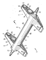
- FIGURE shows a bogie according to the invention in a schematic perspective view.
- the axle assembly 1 is composed of a lower half of the molded part 2 in the figure and an upper half of the molded part 3. Along a substantially horizontally extending parting line 4, the two mold halves 2 and 3 are connected to each other via a weld 5 and define a cavity between them.
- the two mold halves 2 and 3 are each pressed from sheet metal or forged profiles, which may have a wall thickness of a few centimeters, for example about 5 mm.
- Each of the mold halves 2 and 3 is H-shaped with two guide arms halves 6a and 7a or 6b and 7b substantially parallel to each other.
- the guide link halves 6a, 6b; 7a, 7b are each integrally connected to one another via axle body halves 8a and 8b such that the axle body halves 8a, 8b are approximately perpendicular to the guide link halves 6a, 6b; 7a, 7b are lost.
- the guide link halves 6a, 6b; 7a, 7b in each case form guide arms 6 and 7, in the middle region of which the axle body 8 composed of the axle body halves 8a, 8b branches off in the form of an axle tube.
- the axle tube 8 has a diameter of about 200 mm.
- front end 9 and 10 of the guide arm 6 and 7 is at a bearing point on the vehicle chassis (not shown in the figure) articulated.
- the front ends 9, 10 of the guide arm 6, 7 each have a bearing sleeve 11 and 12 formed or arranged.
- the front end 9 and 10 of the guide arm 6 and 7 each have a semi-cylindrical recess into which the annular bearing sleeve 11 and 12 is welded circumferentially.
- the bearing sleeves 11 and 12 themselves may be coated on the inside with, for example, a copper alloy or altogether consist of an alloy with good bearing properties.
- a through hole 13, 14 is provided in each guide arm 6, in which in order to increase the stability of the axle 1 each annular walls 15, 16 are welded.
- these passage openings 13, 14 1 functional elements of a brake system (not shown) may be added close to the axis in the installed state of the axle assembly.
- the contour of the passage openings 13 and 14 and the walls 15 and 16 inserted therein is not limited to a circular shape, but also elliptical or any other geometries can be realized depending on the dimensioning and design of the brake system.
- axle journals 21 and 22 are received in the two opposite side openings of the axle body and pressed in the Achsrohrö réelle and / or welded.
- one or more wheels can be recorded in a known manner in each case.
- the axle journals 21, 22 respectively at their outwardly facing ends threaded portions.
- axle journal 21 and 22 shown in the figure it is also possible instead of the axle journal 21 and 22 shown in the figure to arrange in the axle 8 rolling bearings with which wheel hubs can be rotatably mounted, wherein the outer bearing ring is fixedly connected to the axle 8.
Description
Die Erfindung betrifft ein Achsaggregat mit einer einen starren, z. B. als Achsrohr ausgebildeten Achskörper aufweisenden Fahrzeugachse, mit je einem Führungslenker beidseits der Fahrzeuglängsmittelebene, welcher an einem ersten vorderen Ende an einem chassisfesten Lagerpunkt anlenkbar und davon beabstandet starr mit dem Achskörper verbunden ist, und welcher im Bereich seines dem ersten Ende gegenüberliegenden hinteren Endes das untere Auflager eines Federelements bildet, auf dessen Oberseite sich das Fahrzeugchassis abstützt.The invention relates to a bogie with a rigid, z. B. axle tube formed as the axle having vehicle axle, each with a guide arm on both sides of the vehicle longitudinal center plane, which at a first front end to a chassis-fixed bearing point articulated and spaced rigidly connected to the axle body, and which in the region of its first end opposite the rear end of the forms lower support of a spring element, on the upper side, the vehicle chassis is supported.
Ein derartiges Achsaggregats ist beispielsweise aus der
Aufgabe der vorliegenden Erfindung ist es, ein Achsaggregat der eingangs genannten Art so weiterzubilden, dass der Herstellungs- und Montageaufwand sowie das Gewicht bei geringen Fertigungskosten weiter reduziert werden, ohne die Zuverlässigkeit und Stabilität des Achsaggregats zu verringern.Object of the present invention is to develop a bogie of the type mentioned so that the manufacturing and assembly costs and weight at low production costs are further reduced without reducing the reliability and stability of the axle.
Diese Aufgabe wird erfindungsgemäß bei einem Achsaggregat der eingangs genannten Art dadurch gelöst, dass der Achskörper und die beiden Führungslenker gemeinsam aus zwei jeweils im Wesentlichen einstückigen und miteinander entlang einer z.B. im Wesentliche horizontal verlaufenden Trennfuge verbundenen, insbesondere verschweißten, Formteilhälften bestehen, so dass der Achskörper die beiden Führungslenker starr miteinander verbindet. Die obere Achskörperhälfte und die untere Achskörperhälfte sind hierbei also je im Wesentlichen einstückig mit zwei oberen Führungslenkerhälften bzw. zwei unteren Führungslenkerhälften verbunden, welche sich gegenseitig ergänzen.This object is achieved according to the invention in a bogie of the type mentioned in the fact that the axle body and the two guide arms together of two in each case substantially integral and with each other along a. essentially horizontally extending parting line connected, in particular welded, mold halves exist, so that the axle body rigidly connects the two guide arms together. The upper axle half and the lower axle half are in this case each essentially integrally connected to two upper guide link halves or two lower guide link halves, which complement each other.
Derartige schalenartige Formteilhälften lassen sich mit geeigneten Press- oder Schmiedevorrichtungen mit geringem Aufwand in großen Stückzahlen aus Blech kostengünstig herstellen. Ein Verspannen oder Verschweißen gesonderter Führungslenker z.B. mit dem Achskörper und auch das arbeitsintensive Zusammenfügen der Führungslenker aus mehreren Wandelementen, wie es nach dem Stand der Technik erforderlich ist, kann entfallen. Eine Schweißung ist lediglich zum Verbinden der beiden Formteilhälften im Bereich der z. B. im Wesentlichen horizontal verlaufenden Trennfuge erforderlich, in welcher die Belastungen geringer sind. Zudem ermöglicht das Formpressen der Formteilhälften eine gewichts- und belastungsoptimierte Wandstärkenverteilung in dem Achsaggregat. So ist es beispielsweise möglich, in dem hochbelasteten Bereich der Verbindung der Führungslenker mit dem Achskörper die Materialstärke zu erhöhen und in weniger belasteten Bereichen entsprechend zu verringern. Das erfindungsgemäße Achsaggregat erhält dadurch eine hohe Steifigkeit bei gleichzeitig niedrigem Gewicht.Such shell-like mold halves can be produced inexpensively in small quantities from sheet metal with suitable pressing or forging devices with little effort. A bracing or welding separate control arm, for example, with the axle body and the labor-intensive joining of the guide arm of several wall elements, as required by the prior art, can be omitted. A weld is only for connecting the two mold halves in the region of z. B. substantially horizontally extending parting line required in which the loads are lower. In addition, the compression molding of the mold halves allows a weight and load optimized wall thickness distribution in the axle. So it is for example possible to increase the material thickness in the highly loaded area of the compound of the guide arm with the axle body and in less stressed areas accordingly to reduce. The axle assembly according to the invention thereby obtains a high rigidity and at the same time low weight.
Die Steifigkeit des Achsaggregats kann bei geringem Gewicht dadurch weiter gesteigert werden, dass die beiden Formteilhälften miteinander verbunden einen Hohlraum zwischen sich bilden. Biege- und Torsionsmomente, die auf das Achsaggregat wirken, lassen sich bei dieser Kastenbauweise besonders gut auffangen.The rigidity of the axle assembly can be further increased with low weight, that the two mold halves together form a cavity between them. Bending and torsional moments acting on the axle unit can be absorbed particularly well in this box construction method.
Werden an den vorderen Enden der Führungslenker jeweils eine Lagermuffe zur Verbindung der Führungslenker mit dem Fahrzeugchassis ausgebildet oder angebracht, ist es möglich individuell auf das Fahrzeugchassis abgestimmte Lagermuffen bei gleichbleibender Geometrie des Achsaggregats einzusetzen. Weiter lassen sich auf diese Weise auch unterschiedliche Werkstoffe für die Lagermuffen und die Formteilhälften verwenden, beispielsweise Lagermuffen aus Kupferlegierungen. Die Lagermuffen können durch eine Schweißverbindung besonders einfach und haltbar an den Führungslenkern befestigt sein, wodurch gleichzeitig die Stabilität des Achsaggregats erhöht wird.If in each case a bearing sleeve for connecting the guide link to the vehicle chassis is formed or attached to the front ends of the guide link, it is possible to use individually matched to the vehicle chassis bearing sleeves with the same geometry of the axle assembly. Next can be used in this way, different materials for the bearing sleeves and the mold halves, such as bearing sleeves made of copper alloys. The bearing sleeves can be attached by a welded connection particularly simple and durable to the guide arms, which at the same time the stability of the axle assembly is increased.
Das erfindungsgemäße Achsaggregat ist bei verschiedenen Fahrzeugchassistypen einsetzbar, wenn an den hinteren Enden der Führungslenker jeweils mehrere im Wesentlichen senkrecht zu der Ebene der Trennfuge verlaufende Durchgangsbohrungen vorgesehen sind, um Federelemente an den Führungslenkern zu befestigen. In Abhängigkeit der Größe der Federelemente, die vorzugsweise durch je einen Luftfederbalg gebildet sind, und der Geometrie des Fahrzeugchassis werden die Federelemente in unterschiedlichen Durchgangsbohrungen über beispielsweise einen Gewindezapfen befestigt. Durch die breite Verwendbarkeit des Achsaggregats bei unterschiedlichen Fahrzeugchassistypen können die Fertigungskosten und insbesondere die Kosten für die Formwerkzeuge der Formteilhälften gering gehalten werden. Die Stoßdämpferanbindung kann in an sich bekannter Weise erfolgen.The axle assembly according to the invention can be used with different types of vehicle chassis, if a plurality of through holes extending substantially perpendicular to the plane of the parting line are provided at the rear ends of the guide links in order to fasten spring elements to the guide rods. Depending on the size of the spring elements, which are preferably formed by a respective air spring bellows, and the geometry of the vehicle chassis, the spring elements are fastened in different through holes via, for example, a threaded pin. Due to the wide availability of the Achsaggregats with different Fahrzeugchassistypen the manufacturing costs and in particular the cost of the molds of the mold halves can be kept low. The shock absorber connection can be done in a conventional manner.
Um eine Bremse, wie beispielsweise eine Festsattelscheibenbremse, platzsparend und geschützt anordnen zu können, ist nach einer bevorzugten Ausführungsform der Erfindung in den Führungslenkern zwischen dem mit dem Achskörper verbundenen Bereich und dem vorderen Ende jeweils eine Durchgangsöffnung vorgesehen. In dieser Durchgangsöffnung können Funktionselemente einer Bremsanlage untergebracht werden, ohne den Bauraum im Bereich der Radaufhängung unnötig zu vergrößern. Die Stabilität des Achsaggregats kann dabei weiter gesteigert werden, indem in die Durchgangsöffnung eine ringförmige Wandung eingesetzt und mit den Formteilhälften verschweißt wird.In order to arrange a brake, such as a fixed caliper disc brake, space-saving and protected, according to a preferred embodiment of the invention in the guide arms between the axis body connected to the region and the front end is provided in each case a passage opening. In this passage opening functional elements of a brake system can be accommodated without unnecessarily increasing the space in the wheel suspension. The stability of the axle assembly can be further increased by an annular wall is inserted into the through hole and welded to the mold halves.
Zur Verbindung "von Rädern mit dem Achsaggregat ist vorzugsweise in beiden Seitenöffnungen des Achskörpers jeweils ein Achszapfen starr befestigt. Dieser Achszapfen kann beispielsweise in den als Achsrohr ausgebildeten Achskörper eingepresst und ggf. mit diesem verschweißt oder in sonstiger Weise mit dem Achsaggregat verbunden werden. Auf diese Weise ist es möglich, unterschiedlich dimensionierte Achszapfen bei gleicher Achsaggregatsgeometrie einzusetzen.For connecting "wheels with the axle aggregate, one axle journal is preferably rigidly fastened in each case in both side openings of the axle body." This axle journal can be pressed, for example, into the axle body designed as an axle tube and optionally welded thereto or otherwise connected to the axle aggregate Way, it is possible to use different sized journals for the same axle unit geometry.
Nach einer anderen Ausführungsform der Erfindung sind in beiden Seitenöffnungen des Achskörpers Wälzlager vorgesehen. Die Räder können bei dieser Ausführungsform über eine Verlängerung der Radnabe in der Lagereinheit in dem Achskörper aufgenommen werden. Auch bei dieser Ausgestaltung des Achsaggregats ist die Gestaltung der Räder oder der Bremse weitgehend unabhängig von der Geometrie des Achsaggregats, so dass dieses variabel für unterschiedliche Fahrzeugtypen einsetzbar ist.According to another embodiment of the invention roller bearings are provided in both side openings of the axle body. The wheels can be accommodated in this embodiment via an extension of the wheel hub in the bearing unit in the axle body. Also in this embodiment of the axle assembly is the design of the wheels or the brake largely independent of the geometry of the axle assembly, so that it can be used variably for different vehicle types.
Im Folgenden, wird eine Ausführungsform der Erfindung beispielhaft und unter Bezugnahme auf die Zeichnung erläutert. Die einzige Figur zeigt eine erfindungsgemäßes Achsaggregat in schematischer Perspektivansicht.In the following, an embodiment of the invention is explained by way of example and with reference to the drawing. The single FIGURE shows a bogie according to the invention in a schematic perspective view.
Das Achsaggregat 1 ist aus einer in der Figur unteren Formteilhälfte 2 und einer oberen Formteilhälfte 3 zusammengesetzt. Entlang einer im Wesentlichen horizontal verlaufenden Trennfuge 4 sind die beiden Formteilhälften 2 und 3 miteinander über eine Schweißung 5 verbunden und definieren zwischen sich einen Hohlraum. Die beiden Formteilhälften 2 und 3 sind jeweils aus Blech gepresste oder geschmiedete Profile, die eine Wandstärke von einigen Zentimetern, beispielsweise etwa 5 mm aufweisen können.The
Jede der Formteilhälften 2 und 3 ist H-förmig ausgebildet mit zwei im Wesentlichen zueinander parallelen Führungslenkerhälften 6a und 7a bzw. 6b und 7b. Die Führungslenkerhälften 6a, 6b; 7a, 7b sind jeweils über Achskörperhälften 8a bzw. 8b miteinander einstückig so verbunden, dass die Achskörperhälften 8a, 8b annähernd senkrecht zu den Führungslenkerhälften 6a, 6b; 7a, 7b verlaufen. Die Führungslenkerhälften 6a, 6b; 7a, 7b bilden zusammengesetzt jeweils Führungslenker 6 bzw. 7, in deren mittleren Bereich der aus den Achskörperhälften 8a, 8b zusammengesetzte Achskörper 8 in Form eines Achsrohres abzweigt. In der gezeigten Ausführungsform weist das Achsrohr 8 einen Durchmesser von etwa 200 mm auf.Each of the
Das jeweils in der durch Pfeil F gekennzeichneten Fahrtrichtung vordere Ende 9 bzw. 10 der Führungslenker 6 und 7 ist an einem Lagerpunkt am Fahrzeugchassis (in der Figur nicht dargestellt) anlenkbar. Hierzu ist in den vorderen Enden 9, 10 der Führungslenker 6, 7 jeweils eine Lagermuffe 11 bzw. 12 ausgebildet oder angeordnet. In der in der Figur dargestellten Ausführungsform weist hierzu das vordere Ende 9 bzw. 10 der Führungslenker 6 und 7 jeweils eine halbzylindrische Ausnehmung auf, in welche die ringförmige Lagermuffe 11 bzw. 12 umlaufend eingeschweißt ist. Die Lagermuffen 11 und 12 selbst können innen beispielsweise mit einer Kupferlegierung beschichtet sein oder insgesamt aus einer Legierung mit guten Lagereigenschaften bestehen.The in each case in the direction of travel marked by arrow F
Zwischen den Lagermuffen 11 und 12 und den Abzweigungen des Achskörpers 8 ist in jedem Führungslenker 6 bzw. 7 eine Durchgangsöffnung 13, 14 vorgesehen, in die zur Steigerung der Stabilität des Achsaggregats 1 jeweils ringförmige Wandungen 15, 16 eingschweißt sind. In diesen Durchgangsöffnungen 13, 14 können im Einbauzustand des Achsaggregats 1 Funktionselemente einer Bremsanlage (nicht dargestellt) achsnah aufgenommen sein. Die Kontur der Durchgangsöffnungen 13 und 14 sowie der darin eingesetzten Wandungen 15 und 16 ist dabei nicht auf eine Kreisform beschränkt, vielmehr können in Abhängigkeit der Dimensionierung und Gestaltung der Bremsanlage auch elliptische oder beliebige andere Geometrien realisiert werden.Between the
In den bezüglich der Fahrtrichtung F hinteren abgeflachten Enden 17, 18 der Führungslenker 6, 7 sind drei senkrecht zur vertikalen Fahrzeugmittellängsebene zueinander versetzte Durchgangsbohrungen 19 bzw. 20 vorgesehen. Mittels Gewindezapfen können in jeweils einem oder mehreren der Durchgangsbohrungen 19, 20 Federelemente (nicht dargestellt) an den Führungslenkern 6 bzw. 7 befestigt werden, so dass die hinteren Enden 17, 18 der Führungslenker 6, 7 Auflager für diese Federelemente, wie beispielsweise einen Luftfederbalg, bilden. Auf der Oberseite der Federelemente stützt sich dann seinerseits das Fahrzeugchassis ab. Durch das Vorsehen mehrerer Durchgangsbohrungen 19, 20 in den Führungslenkern 6 und 7 ist es möglich, die Federelemente in Abhängigkeit der Abmessungen des Fahrzeugchassis in unterschiedlichen Abständen von der senkrechten Fahrzeuglängsmittelebene zu befestigen.In the respect to the direction of travel F rear
In der in der Figur dargestellten Ausführungsform sind in die beiden einander gegenüberliegenden Seitenöffnungen des Achskörpers 8 Achszapfen 21 und 22 aufgenommen und in der Achsrohröffnung verpresst und/oder verschweißt. Auf den Achszapfen 21 und 22 können in bekannter Weise jeweils ein oder mehrere Räder (nicht dargestellt) aufgenommen werden. Hierzu weisen die Achszapfen 21, 22 an ihren nach außen gewandten Enden jeweils Gewindeabschnitte auf.In the embodiment shown in the figure 8
Nach einer alternativen Ausführungsform ist es auch möglich statt der in der Figur gezeigten Achszapfen 21 und 22 in dem Achskörper 8 Wälzlager anzuordnen, mit denen Radnaben drehbar gelagert werden können, wobei der äußere Lagerring fest mit dem Achskörper 8 verbunden ist.According to an alternative embodiment, it is also possible instead of the
- 11
- Achsaggregatbogie
- 22
- untere Formteilhälftelower half of the molding
- 33
- obere Formteilhälfteupper mold half
- 44
- Trennfugeparting line
- 55
- Schweißungwelding
- 66
- FührungslenkerTrailing arm
- 77
- FührungslenkerTrailing arm
- 88th
- Achskörper (Achsrohr)Axle body (axle tube)
- 99
-
vorderes Ende des Führungslenkers 6front end of the
guide arm 6 - 1010
-
vorderes Ende des Führungslenkers 7front end of the
guide arm 7 - 1111
- Lagermuffebearing sleeve
- 1212
- Lagermuffebearing sleeve
- 1313
- DurchgangsöffnungThrough opening
- 1414
- DurchgangsöffnungThrough opening
- 1515
- ringförmige Wandungannular wall
- 1616
- ringförmige Wandungannular wall
- 1717
-
hinteres Ende des Führungslenkers 6Rear end of the
guide arm 6 - 1818
-
hinteres Ende des Führungslenkers 7Rear end of the
guide arm 7 - 1919
- DurchgangsbohrungenThrough holes
- 2020
- DurchgangsbohrungenThrough holes
- 2121
- Achszapfenjournal
- 2222
- Achszapfenjournal
- FF
- Fahrtrichtungdirection of travel
Claims (7)
- An axle assembly comprising a vehicle axle having an axle body (8) that is rigid and that is provided, for example, in the form of an axle tube, having one radius arm (6, 7) each on both sides of the vehicle's longitudinal median plane which, at a first front end (9, 10) can be articulated on a bearing point fixed on the chassis and which, at a distance therefrom, is rigidly joined to the axle body (8) and which forms, in the region of its rear end (17, 18) that is opposite the first end (9, 10), the lower support of a spring element on whose upper side the vehicle chassis is supported, characterized in that the axle body (8) and both radius arms (6, 7) are formed together from two essentially one-piece shaped part halves which are joined, in particular welded, to one another along a parting line (4) which extends along an e.g. essentially horizontal plane, so that the axle body (8) rigidly joins both radius arms (6, 7) to one another.
- The axle assembly according to claim 1, characterized in that the two shaped part halves (2, 3) when joined, form a hollow space between them.
- The axle assembly according to claim 1 or 2, characterized in that a bearing sleeve (11, 12) each is formed or attached, in particular welded, to the front ends (9, 10) of the radius arms (6, 7) to connect the radius arms (6, 7) with the vehicle chassis.
- The axle assembly according to any one of the claims 1 to 3, characterized in that several through bores (19, 20) that extend essentially at a right angle to the parting plane of the shaped part halves (2, 3) are provided on each of the rear ends (17, 18) of the radius arms (6, 7), in order to fasten spring elements, in particular a pneumatic spring bellows each, to the radius arms (6, 7).
- The axle assembly according to any one of the claims 1 to 4, characterized in that a through hole (13, 14) each is provided in the radius arms (6, 7) between the region connected with the axle body (8) and the front end (9, 10).
- The axle assembly according to any one of the claims 1 to 5, characterized in that an axle journal (21, 22) each is rigidly fastened in two side openings of the axle body (8).
- The axle assembly according to any one of the claims 1 to 5, characterized in that roller bearings for receiving a wheel hub part are provided in two side openings of the axle body (8).
Applications Claiming Priority (5)
| Application Number | Priority Date | Filing Date | Title |
|---|---|---|---|
| DE10113674 | 2001-03-21 | ||
| DE10113674 | 2001-03-21 | ||
| DE10118523 | 2001-04-14 | ||
| DE10118523A DE10118523C5 (en) | 2001-03-21 | 2001-04-14 | bogie |
| PCT/EP2002/003002 WO2002074563A1 (en) | 2001-03-21 | 2002-03-19 | Axle assembly |
Publications (2)
| Publication Number | Publication Date |
|---|---|
| EP1370432A1 EP1370432A1 (en) | 2003-12-17 |
| EP1370432B1 true EP1370432B1 (en) | 2008-10-15 |
Family
ID=26008845
Family Applications (1)
| Application Number | Title | Priority Date | Filing Date |
|---|---|---|---|
| EP02722239A Expired - Lifetime EP1370432B1 (en) | 2001-03-21 | 2002-03-19 | Axle assembly |
Country Status (7)
| Country | Link |
|---|---|
| EP (1) | EP1370432B1 (en) |
| CN (1) | CN100379589C (en) |
| AU (1) | AU2002253142B2 (en) |
| CA (1) | CA2442007A1 (en) |
| DE (2) | DE10118523C5 (en) |
| ES (1) | ES2314051T3 (en) |
| WO (1) | WO2002074563A1 (en) |
Families Citing this family (6)
| Publication number | Priority date | Publication date | Assignee | Title |
|---|---|---|---|---|
| US6749209B2 (en) * | 2002-05-01 | 2004-06-15 | Dana Corporation | Suspension and axle assembly |
| DE102006025275A1 (en) * | 2006-05-31 | 2007-12-06 | Daimlerchrysler Ag | Axle-bridge for motor vehicle, comprises a middle carrier unit having two half-shells, which are joined along an imaginary contact plane, and two axle connection parts arranged at opposite sides coaxial to the carrier unit |
| DE102006037356B4 (en) * | 2006-08-09 | 2011-02-03 | Saf-Holland Gmbh | bogie |
| US8544961B2 (en) * | 2010-09-02 | 2013-10-01 | Hendrickson Usa, L.L.C. | Fabricated vehicle axle |
| DE102011083221B4 (en) * | 2011-09-22 | 2017-02-09 | Saf-Holland Gmbh | Axle bearings for commercial vehicles |
| CN116330890B (en) * | 2023-05-29 | 2023-08-01 | 吉林省威创机电工程有限公司 | Integrated casting trailer axle housing assembly |
Family Cites Families (11)
| Publication number | Priority date | Publication date | Assignee | Title |
|---|---|---|---|---|
| US2685479A (en) * | 1944-11-25 | 1954-08-03 | Rockwell Spring & Axle Co | Tubular axle beam |
| IT1210838B (en) * | 1987-06-26 | 1989-09-29 | Fiat Auto Spa | PROCEDURE FOR THE ASSEMBLY OF A TERMINAL OF A WHEEL BRIDGE FOR MOTOR VEHICLES AND TERMINAL REALIZED WITH SUCH PROCEDURE |
| CN2141776Y (en) * | 1992-11-12 | 1993-09-08 | 文登市通用机床厂 | Rear axle for car |
| CN2230678Y (en) * | 1995-11-30 | 1996-07-10 | 中国人民解放军第七四○七工厂 | Axle assembly of automobile |
| DE19617929A1 (en) * | 1996-05-06 | 1997-12-11 | Sauer Achsenfab | Suspension for a vehicle axle |
| US5690353A (en) * | 1996-05-09 | 1997-11-25 | Suspensions Incorporated | Suspension system with improved beam |
| DE19638082C1 (en) * | 1996-09-19 | 1998-02-05 | Sauer Achsenfab | Suspension for a vehicle axle |
| US6322089B1 (en) * | 1997-10-04 | 2001-11-27 | Otto Sauer Achsenfabrik Keilberg | Suspension for motor vehicles |
| DE19818698B4 (en) * | 1997-11-21 | 2010-12-02 | Saf-Holland Gmbh | Suspension for a vehicle axle |
| CN2374376Y (en) * | 1999-04-29 | 2000-04-19 | 顺德富华工程机械制造有限公司 | Integral axle of semitrailer |
| GB9925415D0 (en) * | 1999-10-28 | 1999-12-29 | Meritor Heavy Vehicle Sys Ltd | Vehicle axle |
-
2001
- 2001-04-14 DE DE10118523A patent/DE10118523C5/en not_active Expired - Fee Related
-
2002
- 2002-03-19 EP EP02722239A patent/EP1370432B1/en not_active Expired - Lifetime
- 2002-03-19 ES ES02722239T patent/ES2314051T3/en not_active Expired - Lifetime
- 2002-03-19 WO PCT/EP2002/003002 patent/WO2002074563A1/en active IP Right Grant
- 2002-03-19 CA CA002442007A patent/CA2442007A1/en not_active Abandoned
- 2002-03-19 AU AU2002253142A patent/AU2002253142B2/en not_active Ceased
- 2002-03-19 DE DE50212896T patent/DE50212896D1/en not_active Expired - Lifetime
- 2002-03-19 CN CNB028069706A patent/CN100379589C/en not_active Expired - Fee Related
Also Published As
| Publication number | Publication date |
|---|---|
| CN100379589C (en) | 2008-04-09 |
| DE10118523C5 (en) | 2009-06-25 |
| AU2002253142B2 (en) | 2006-09-28 |
| DE10118523B4 (en) | 2006-09-07 |
| WO2002074563A1 (en) | 2002-09-26 |
| CN1527770A (en) | 2004-09-08 |
| ES2314051T3 (en) | 2009-03-16 |
| CA2442007A1 (en) | 2002-09-26 |
| DE50212896D1 (en) | 2008-11-27 |
| DE10118523A1 (en) | 2002-09-26 |
| EP1370432A1 (en) | 2003-12-17 |
Similar Documents
| Publication | Publication Date | Title |
|---|---|---|
| DE102006037356B4 (en) | bogie | |
| DE102006041567B4 (en) | Verbundlenkerachsaufhängungen | |
| DE4213105C2 (en) | Front suspension for motor vehicles, especially buses | |
| DE102009031846A1 (en) | Rear axle of the compound type of steering wheel for motor vehicles | |
| DE102006015671A1 (en) | Axle body for a vehicle comprises a transverse pipe arranged on or close to the imaginary connecting axis of the wheel support between longitudinal connecting rods and having ends welded to the connecting rods from inside the vehicle | |
| DE3331282A1 (en) | WHEEL SUSPENSION FOR STEERING FRONT WHEELS OF MOTOR VEHICLES | |
| EP1842700B1 (en) | Vehicle axle | |
| EP1419056B2 (en) | Rigid axle for a vehicle, comprising integrated trailing arms | |
| EP0940320B1 (en) | Chassis for a heavy-duty utility vehicle | |
| DE3521361C2 (en) | ||
| DE19619189A1 (en) | Independent wheel suspension for an air-sprung, steerable wheel of a bus or truck | |
| EP1370432B1 (en) | Axle assembly | |
| EP2495117A2 (en) | Support for pivotable mounting of the axle guide of a vehicle axle | |
| EP2952361B1 (en) | Constructed wheel support | |
| EP0940319B1 (en) | Chassis of a heavy utility vehicle | |
| DE3526272A1 (en) | Axle bracket for commercial vehicles | |
| EP1159147B1 (en) | Composite pivot pin | |
| EP3290298B1 (en) | Commercial vehicle single wheel suspension with monolithic spindle | |
| EP3148824B1 (en) | Axle assembly | |
| DE202015102551U1 (en) | Axle | |
| EP3946987A1 (en) | Military utility vehicle | |
| EP3130489B1 (en) | Wheel suspension for a motor vehicle | |
| EP0940323B1 (en) | Chassis for a heavy-duty utility vehicle | |
| EP0940324B1 (en) | Chassis for a heavy-duty utility vehicle | |
| DE3707155C2 (en) |
Legal Events
| Date | Code | Title | Description |
|---|---|---|---|
| PUAI | Public reference made under article 153(3) epc to a published international application that has entered the european phase |
Free format text: ORIGINAL CODE: 0009012 |
|
| 17P | Request for examination filed |
Effective date: 20030918 |
|
| AK | Designated contracting states |
Kind code of ref document: A1 Designated state(s): AT BE CH CY DE DK ES FI FR GB GR IE IT LI LU MC NL PT SE TR |
|
| RAP1 | Party data changed (applicant data changed or rights of an application transferred) |
Owner name: OTTO SAUER ACHSENFABRIK KEILBERG KG |
|
| RAP1 | Party data changed (applicant data changed or rights of an application transferred) |
Owner name: SAF-HOLLAND GMBH |
|
| GRAP | Despatch of communication of intention to grant a patent |
Free format text: ORIGINAL CODE: EPIDOSNIGR1 |
|
| RBV | Designated contracting states (corrected) |
Designated state(s): DE ES FR GB IT NL |
|
| GRAS | Grant fee paid |
Free format text: ORIGINAL CODE: EPIDOSNIGR3 |
|
| GRAA | (expected) grant |
Free format text: ORIGINAL CODE: 0009210 |
|
| AK | Designated contracting states |
Kind code of ref document: B1 Designated state(s): DE ES FR GB IT NL |
|
| REG | Reference to a national code |
Ref country code: GB Ref legal event code: FG4D Free format text: NOT ENGLISH |
|
| REF | Corresponds to: |
Ref document number: 50212896 Country of ref document: DE Date of ref document: 20081127 Kind code of ref document: P |
|
| REG | Reference to a national code |
Ref country code: ES Ref legal event code: FG2A Ref document number: 2314051 Country of ref document: ES Kind code of ref document: T3 |
|
| PLBE | No opposition filed within time limit |
Free format text: ORIGINAL CODE: 0009261 |
|
| STAA | Information on the status of an ep patent application or granted ep patent |
Free format text: STATUS: NO OPPOSITION FILED WITHIN TIME LIMIT |
|
| 26N | No opposition filed |
Effective date: 20090716 |
|
| REG | Reference to a national code |
Ref country code: ES Ref legal event code: FD2A Effective date: 20090320 |
|
| PG25 | Lapsed in a contracting state [announced via postgrant information from national office to epo] |
Ref country code: ES Free format text: LAPSE BECAUSE OF NON-PAYMENT OF DUE FEES Effective date: 20090320 |
|
| PGFP | Annual fee paid to national office [announced via postgrant information from national office to epo] |
Ref country code: FR Payment date: 20120403 Year of fee payment: 11 |
|
| PGFP | Annual fee paid to national office [announced via postgrant information from national office to epo] |
Ref country code: IT Payment date: 20120327 Year of fee payment: 11 |
|
| REG | Reference to a national code |
Ref country code: FR Ref legal event code: ST Effective date: 20131129 |
|
| PG25 | Lapsed in a contracting state [announced via postgrant information from national office to epo] |
Ref country code: FR Free format text: LAPSE BECAUSE OF NON-PAYMENT OF DUE FEES Effective date: 20130402 |
|
| PG25 | Lapsed in a contracting state [announced via postgrant information from national office to epo] |
Ref country code: IT Free format text: LAPSE BECAUSE OF NON-PAYMENT OF DUE FEES Effective date: 20130319 |
|
| PGFP | Annual fee paid to national office [announced via postgrant information from national office to epo] |
Ref country code: NL Payment date: 20150323 Year of fee payment: 14 |
|
| REG | Reference to a national code |
Ref country code: NL Ref legal event code: MM Effective date: 20160401 |
|
| PG25 | Lapsed in a contracting state [announced via postgrant information from national office to epo] |
Ref country code: NL Free format text: LAPSE BECAUSE OF NON-PAYMENT OF DUE FEES Effective date: 20160401 |
|
| PGFP | Annual fee paid to national office [announced via postgrant information from national office to epo] |
Ref country code: GB Payment date: 20170327 Year of fee payment: 16 |
|
| PGFP | Annual fee paid to national office [announced via postgrant information from national office to epo] |
Ref country code: DE Payment date: 20180124 Year of fee payment: 17 |
|
| GBPC | Gb: european patent ceased through non-payment of renewal fee |
Effective date: 20180319 |
|
| PG25 | Lapsed in a contracting state [announced via postgrant information from national office to epo] |
Ref country code: GB Free format text: LAPSE BECAUSE OF NON-PAYMENT OF DUE FEES Effective date: 20180319 |
|
| REG | Reference to a national code |
Ref country code: DE Ref legal event code: R119 Ref document number: 50212896 Country of ref document: DE |
|
| PG25 | Lapsed in a contracting state [announced via postgrant information from national office to epo] |
Ref country code: DE Free format text: LAPSE BECAUSE OF NON-PAYMENT OF DUE FEES Effective date: 20191001 |