EP1370112A2 - System and method for adaptive multi-sensor arrays - Google Patents
System and method for adaptive multi-sensor arrays Download PDFInfo
- Publication number
- EP1370112A2 EP1370112A2 EP03253552A EP03253552A EP1370112A2 EP 1370112 A2 EP1370112 A2 EP 1370112A2 EP 03253552 A EP03253552 A EP 03253552A EP 03253552 A EP03253552 A EP 03253552A EP 1370112 A2 EP1370112 A2 EP 1370112A2
- Authority
- EP
- European Patent Office
- Prior art keywords
- signal
- covariance matrix
- arrival
- estimating
- microphone array
- Prior art date
- Legal status (The legal status is an assumption and is not a legal conclusion. Google has not performed a legal analysis and makes no representation as to the accuracy of the status listed.)
- Granted
Links
Images

Classifications
-
- H—ELECTRICITY
- H04—ELECTRIC COMMUNICATION TECHNIQUE
- H04R—LOUDSPEAKERS, MICROPHONES, GRAMOPHONE PICK-UPS OR LIKE ACOUSTIC ELECTROMECHANICAL TRANSDUCERS; ELECTRIC HEARING AIDS; PUBLIC ADDRESS SYSTEMS
- H04R3/00—Circuits for transducers
- H04R3/005—Circuits for transducers for combining the signals of two or more microphones
-
- G—PHYSICS
- G06—COMPUTING OR CALCULATING; COUNTING
- G06F—ELECTRIC DIGITAL DATA PROCESSING
- G06F2218/00—Aspects of pattern recognition specially adapted for signal processing
- G06F2218/22—Source localisation; Inverse modelling
-
- G—PHYSICS
- G10—MUSICAL INSTRUMENTS; ACOUSTICS
- G10L—SPEECH ANALYSIS TECHNIQUES OR SPEECH SYNTHESIS; SPEECH RECOGNITION; SPEECH OR VOICE PROCESSING TECHNIQUES; SPEECH OR AUDIO CODING OR DECODING
- G10L21/00—Speech or voice signal processing techniques to produce another audible or non-audible signal, e.g. visual or tactile, in order to modify its quality or its intelligibility
- G10L21/02—Speech enhancement, e.g. noise reduction or echo cancellation
- G10L21/0208—Noise filtering
- G10L21/0216—Noise filtering characterised by the method used for estimating noise
- G10L2021/02161—Number of inputs available containing the signal or the noise to be suppressed
- G10L2021/02166—Microphone arrays; Beamforming
-
- H—ELECTRICITY
- H04—ELECTRIC COMMUNICATION TECHNIQUE
- H04R—LOUDSPEAKERS, MICROPHONES, GRAMOPHONE PICK-UPS OR LIKE ACOUSTIC ELECTROMECHANICAL TRANSDUCERS; ELECTRIC HEARING AIDS; PUBLIC ADDRESS SYSTEMS
- H04R2430/00—Signal processing covered by H04R, not provided for in its groups
- H04R2430/20—Processing of the output signals of the acoustic transducers of an array for obtaining a desired directivity characteristic
- H04R2430/21—Direction finding using differential microphone array [DMA]
-
- H—ELECTRICITY
- H04—ELECTRIC COMMUNICATION TECHNIQUE
- H04R—LOUDSPEAKERS, MICROPHONES, GRAMOPHONE PICK-UPS OR LIKE ACOUSTIC ELECTROMECHANICAL TRANSDUCERS; ELECTRIC HEARING AIDS; PUBLIC ADDRESS SYSTEMS
- H04R2499/00—Aspects covered by H04R or H04S not otherwise provided for in their subgroups
- H04R2499/10—General applications
- H04R2499/13—Acoustic transducers and sound field adaptation in vehicles
-
- H—ELECTRICITY
- H04—ELECTRIC COMMUNICATION TECHNIQUE
- H04R—LOUDSPEAKERS, MICROPHONES, GRAMOPHONE PICK-UPS OR LIKE ACOUSTIC ELECTROMECHANICAL TRANSDUCERS; ELECTRIC HEARING AIDS; PUBLIC ADDRESS SYSTEMS
- H04R25/00—Electric hearing aids
- H04R25/40—Arrangements for obtaining a desired directivity characteristic
- H04R25/407—Circuits for combining signals of a plurality of transducers
Definitions
- the present invention relates to signal processing, and more particularly to an adaptive multi-sensor array and method thereof.
- Microphone arrays are used in various devices, such as hearing aids and speech recognition applications.
- One problem with these devices is noise, and the elimination of noise from a signal received by the microphone array.
- the proposed solutions can be divided into three classes of microphone array schemes: side-lobe canceller, beamformer, and differential microphone array (DMA).
- side-lobe canceller beamformer
- DMA differential microphone array
- Many of the known adaptive methods for reducing noise address the first two classes, side-lobe cancellers and beamformers.
- DMA differential microphone array
- differential microphone arrays Two works that discuss differential microphone arrays are H. Teutsch and G.W. Elko, “First and second-order adaptive differential microphone arrays", 7 th International Workshop on Acoustic Echo and Noise Control, pages 35-38, 2001; and U.S. Patent No. 5,473,701 to J. Cezanne and G.W. Elko entitled "Adaptive Microphone Array”.
- the differential microphone array works implement an adaptation by minimizing an output variance.
- the proposed solutions implementing differential microphone arrays utilize an optimization criterion, which is a total output power or energy.
- the criterion is of the form T1+T2 where T1 is the output energy due to the signal, and T2 the output energy due to the noise.
- the optimization problem is: min(T1 + T2) .
- This optimization problem has an inherent limitation; when the source position is in a null-allowed region, then either no processing is done, or if the optimization problem is solved, it cancels a target source.
- a parameter beta is implemented that adjusts the directivity pattern.
- an adaptive differential microphone array method comprises receiving a signal, estimating a measured signal spectral covariance matrix of the signal, and estimating a direction of arrival of the signal based on the measured signal spectral covariance matrix of the signal.
- the method further comprises determining a fractional delay, and applying a differential microphone array filter to the signal based on the direction of arrival and the fractional delay.
- the signal is a sample.
- Determining the fractional delay comprises obtaining the fractional delay from a look-up table based on the direction of arrival through a maximization of a weighted directivity index, and applying the fractional delay in the differential microphone array filter.
- an adaptive differential microphone array method comprises receiving a signal, and estimating a measured signal spectral covariance matrix of the signal, and estimating a direction of arrival of the signal.
- the method further comprises determining a presence of a source of interest in the signal based on the direction of arrival of the signal, a noise spectral covariance matrix of the signal, and a source signal spectral power of the signal, estimating the noise spectral covariance matrix based on a determination of the presence of the source of interest and the measured signal spectral covariance matrix of the signal.
- the method comprises estimating a source signal spectral power of the signal according to the presence of the source of interest the noise spectral covariance matrix and the noise spectral covariance matrix, and applying a differential microphone array filter to signal according to the direction of arrival, the noise spectral covariance matrix, and the source signal spectral power of the signal.
- the signal is a sample.
- the method further comprising determining a fractional delay, and applying the fractional delay in the differential microphone array filter.
- Determining the two fractional delays further comprises determining
- a digital processor for reducing a noise portion of a signal comprises means for estimating a measured signal spectral covariance matrix of the signal, means for estimating a direction of arrival of the signal, and a differential microphone array filter.
- the digital processor further comprises a voice activity detector outputting a signal indicating the presence of a source of interest in the signal, means for estimating a noise spectral covariance matrix based on the signal indicating the presence of a source of interest in the signal and the measured signal spectral covariance matrix, and means for estimating a source signal spectral power of the signal according to the noise spectral covariance matrix, and the measured signal spectral covariance matrix.
- a program storage device readable by machine, tangibly embodying a program of instructions executable by the machine to perform method steps for an adaptive differential microphone array method.
- the method steps comprising receiving a signal, estimating a measured signal spectral covariance matrix of the signal, and estimating a direction of arrival of the signal based on the measured signal spectral covariance matrix of the signal.
- the method further comprising determining a fractional delay, and applying a differential microphone array filter to the signal based on the direction of arrival and the fractional delay.
- a program storage device readable by machine, tangibly embodying a program of instructions executable by the machine to perform method steps for an adaptive differential microphone array method.
- the method steps comprise receiving a signal, estimating a measured signal spectral covariance matrix of the signal, and estimating a direction of arrival of the signal.
- the method further comprises determining a presence of a source of interest in the signal based on the direction of arrival of the signal, a noise spectral covariance matrix of the signal, and a source signal spectral power of the signal, and estimating the noise spectral covariance matrix based on a determination of the presence of the source of interest and the measured signal spectral covariance matrix of the signal.
- the method comprises estimating a source signal spectral power of the signal according to the presence of the source of interest the noise spectral covariance matrix and the noise spectral covariance matrix, and applying a differential microphone array filter to signal according to the direction of arrival, the noise spectral covariance matrix, and the source signal spectral power of the signal.
- a system and method for adaptive array signal processing for multi-sensor arrays estimates a direction of arrival (DOA) of a main source.
- DOA direction of arrival
- a differential microphone array DMA
- the differential microphone array filter parameters are tuned using an estimate of the direction of arrival of the main source, an estimate of a source spectral power, and an estimate of a noise field spectral covariance matrix.
- an adaptive multi-sensor array can be implemented in a hearing aid.
- adaptive multi-sensor arrays are not limited to hearing aids, and can be applied to any microphone array based audio processing system, such as for improving the quality of a voice in a car environment, or the quality of a patient voice while in a gantry of a CT scanner.
- An estimate of the direction of arrival of a dominant source is obtained, as well as the source spectral power, and the noise field spectral covariance matrix. Based on the estimates of the direction of arrival of the dominant source, the source spectral power, and the noise field spectral covariance matrix a differential microphone array scheme can be adapted to reduce a noise level in a recorded signal.
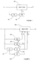
- a direction of arrival based adaptive differential microphone array method is shown.
- a voice activity detector (VAD) and direction of arrival based adaptive differential microphone array method is depicted.
- the differential microphone array filter coefficients are updated from a look-up table based on the current estimate of direction of arrival.
- the differential microphone array filter coefficients are obtained as optimizers of a modified directivity index that takes into account the estimated source direction of arrival, as well as the current estimate of the noise spectral covariance matrix and source spectral power.
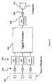
- FIG. 3 A system for implementing the methods of Figure 1 and Figure 2 is shown in Figure 3.
- the array of microphones 301 converts an acoustic pressure into an electric signal.
- the electric signal is amplified by amplifiers A 302 and converted into a digital domain by the analog-to-digital (A/D) converters 303.
- the digitized measured signals can be denoted by x 1 ,... x D , where D is the number of microphones.
- the signal in the digital domain is processed by a digital processor 304, described with respect to Figures 1 and 2.
- a processed signal is converted back into the analog domain by a digital-to-analog (D/A) converter 305.
- the signal is amplified by amplifier 306 and converted into a pressure wave by the loudspeaker 307.
- the present invention may be implemented in various forms of hardware, software, firmware, special purpose processors, or a combination thereof.
- the present invention may be implemented in software as an application program tangibly embodied on a program storage device.
- the application program may be uploaded to, and executed by, a machine comprising any suitable architecture.
- a computer system 401 for implementing the present invention can comprise, inter alia, a central processing unit (CPU) 402, a memory 403 and an input/output (I/O) interface 404.
- the computer system 401 is generally coupled through the I/O interface 404 to a display 405 and various input devices 406 such as a mouse and keyboard.
- the support circuits can include circuits such as cache, power supplies, clock circuits, and a communications bus.
- the memory 403 can include random access memory (RAM), read only memory (ROM), disk drive, tape drive, etc., or a combination thereof.
- the present invention can be implemented as a routine 407 that is stored in memory 403 and executed by the CPU 402 to process the signal from the signal source 408.
- the computer system 401 is a general purpose computer system that becomes a specific purpose computer system when executing the routine 407 of the present invention.
- the computer platform 401 also includes an operating system and micro instruction code.
- the various processes and functions described herein may either be part of the micro instruction code or part of the application program (or a combination thereof) which is executed via the operating system.
- various other peripheral devices may be connected to the computer platform such as an additional data storage device and a printing device.
- the direction of arrival based adaptive differential microphone array method comprises three blocks: estimation of the measured signal spectral covariance matrix R x 101, estimation of direction of arrival 102, and differential microphone array filter, Filter1 103.
- the estimation of the measured signal spectral covariance matrix R x 101 comprises initializing R x for every frequency.
- the initialization can be written as: where M is a number of samples.
- the initialization can be, for example, to zero (0).
- For each input, x a windowed Fourier transform is determined.
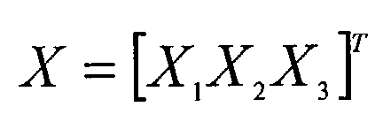
- the windowed Fourier transform can be determined using the last M samples x 1 ( t) , x 1 ( t -1),..., x 1 ( t - M +1), x 2 ( t ), x 2 ( t -1),..., x 2 ( t - M +1), x 3 ( t ), x 3 ( t -1),..., x 3 ( t - M +1) where the transform is written as: where w (0),..., w ( M -1) is the window, and for every ⁇ ⁇ S ( ⁇ is called frequency). R x is updated at every frequency. The updated R x is based on a previous frame and a present frame.
- ⁇ df s / c , where d is the distance between two adjacent microphones, f s is the sampling frequency, and c is the speed of sound.
- the fractional delay measures the time it takes between when a sound arrives at a first microphone and when the sound arrives at a second microphone.
- the differential microphone array filter is used to determine the measured signals for each input, x D .
- the differential microphone array uses parameters ⁇ 1 , ⁇ 2 obtained from a look-up table.
- the look-up table determines delays d 1 , d 2 for each estimated direction of arrival.
- the look-up table gives a list of ⁇ 1 , ⁇ 2 in an optimization cost criterion J ( d 1 , d 2 ).
- the parameters ⁇ 1 , ⁇ 2 e.g., optimized values of d 1 , d 2 , depend on the direction of arrival through a maximization of a weighted directivity index.
- the directivity index suppresses certain directions and amplifies others. Suppressed directions include those directions from which noise originates. Amplified directions include those with a source of interest.
- An aligned signal is determined based on two or more signals received at corresponding sensors.
- the two or more signals are aligned using the values for fractional delays ⁇ 1 , ⁇ 2 .
- the parameters ⁇ 1 , ⁇ 2 depend on the direction of arrival through a maximization of a weighted directivity index.
- the optimization cost criterion J ( d 1 , d 2 ) be given by a weighted average of frequency dependent normalized signal-to-noise ratios is determined.
- the optimization cost criterion takes into account where ⁇ and obtained in the direction of arrival estimation, a weight, e.g., an articulation index, and a matrix for determining a spectral power of noise in a diffuse noise environment.
- the parameters ⁇ 1 , ⁇ 2 are obtained as:
- the voice activity detector and direction of arrival based adaptive differential microphone array method comprises an estimation of R x 201, an estimation of the direction of arrival 202, a voice activity detector 203, an estimation of R n 204, an estimation of R s 205, and a differential microphone array filter, Filter2 206.
- the voice activity detector discriminates between speech and non-speech, and can discard non-speech portions of a signal.
- the voice activity detector 203 outputs a binary signal: 0 or 1, 0 when a source of interest is not present, and 1 when a source of interest is present.
- the noise spectral covariance matrix R n 204 is adapted at every frequency. For example, as: where ⁇ is the noise learning rate, and X ( ⁇ ) is the vector of the components in the windowed Fourier transform.
- the source signal spectral power R S 205 is estimated by a spectral subtraction method. For example: where ⁇ SS >1 is a coefficient.
- Various spectral subtraction methods can be used, these are known in art, for example, IEEE Transactions on Acoustics, Speech and Signal Processing, vol. ASSP 27, No. 2, Apr. 1979, Steven Boll, Suppression of Acoustic Noise in Speech Using Spectral Subtraction, pp. 113-120.
- the differential microphone array filter 206 Filter2, Filters the measured signals x D .
- the measured signals x 1 , x 2 , x 3 are filtered by the differential microphone array filter using the aligned signal.
- ⁇ 1 , ⁇ 2 are obtained as the solution of the optimization problem: where the criterion I ( d 1 , d 2 ) takes into account the following variables: ⁇ and is obtained in the direction of arrival estimations, R s ( ⁇ ) is a signal spectral power, and R ns ( ⁇ ) is a noise spectral covariance matrix. This criterion represents a generalization of the directivity index.
- a system comprises an array of close-by microphones 301; the distance between any two adjacent microphones is about 1 cm.
- Amplifiers 302 and A/D converters 303 are provided in series, one of each for each microphone.
- a digital processor 304 is coupled to the A/D converters 303.
- a D/A converter 305 is coupled to the digital processor 304.
- An amplifier 306 and loudspeaker 307 can be provided, coupled in series from the D/A converter 305.
- the direction of arrival estimation can be done less frequently than the differential microphone array filtering; more specifically, the differential microphone array filtering is done at the sampling rate of the digitized signal.
- the frequency of the direction of arrival estimation depends on the processing power of the digital processor, and can be done after every M samples, or after a longer time.
- Fractional delay parameters of the differential microphone array filter are determined on-line and the solutions for the fractional delay parameters for each estimated direction of arrival are stored in a look-up table.
- the aligned signal is determined less frequently than the differential microphone array filtering.
- the differential microphone array filtering is done at the sampling rate, whereas the direction of arrival estimation and voice activity detector decision depend on the processing power of the digital processor, and can be done after every M samples, or after a longer time.
- the aligned signal is determined on a grid in d 1 , d 2 parameters space with a resolution depending on the processing power available; a step size is about 0:01 per sample.
- the fractional delays are implemented by FIR (Finite Impulse Response) filters.
- the differential microphone array can be implemented in the filter bank approach.
Landscapes
- Health & Medical Sciences (AREA)
- General Health & Medical Sciences (AREA)
- Otolaryngology (AREA)
- Physics & Mathematics (AREA)
- Engineering & Computer Science (AREA)
- Acoustics & Sound (AREA)
- Signal Processing (AREA)
- Circuit For Audible Band Transducer (AREA)
- Obtaining Desirable Characteristics In Audible-Bandwidth Transducers (AREA)
- Measurement Of Velocity Or Position Using Acoustic Or Ultrasonic Waves (AREA)
Abstract
Description








Claims (16)
- An adaptive differential microphone array method comprises:receiving a signal;estimating a measured signal spectral covariance matrix of the signal;estimating a direction of arrival of the signal based on the measured signal spectral covariance matrix of the signal;determining a fractional delay; andapplying a differential microphone array filter to the signal based on the direction of arrival and the fractional delay.
- The method of claim 1, wherein the signal is a sample.
- The method of claim 1, wherein determining the fractional delay comprises:obtaining the fractional delay from a look-up table based on the direction of arrival through a maximization of a weighted directivity index; andapplying the fractional delay in the differential microphone array filter.
- An adaptive differential microphone array method comprises:receiving a signal;estimating a measured signal spectral covariance matrix of the signal;estimating a direction of arrival of the signal;determining a presence of a source of interest in the signal based on the direction of arrival of the signal, a noise spectral covariance matrix of the signal, and a source signal spectral power of the signal;estimating the noise spectral covariance matrix based on a determination of the presence of the source of interest and the measured signal spectral covariance matrix of the signal;estimating a source signal spectral power of the signal according to the presence of the source of interest the noise spectral covariance matrix and the noise spectral covariance matrix; andapplying a differential microphone array filter to signal according to the direction of arrival, the noise spectral covariance matrix, and the source signal spectral power of the signal.
- The method of claim 4, wherein the signal is a sample.
- The method of claim 4, further comprising:determining a fractional delay; andapplying the fractional delay in the differential microphone array filter.
- The method of claim 6, wherein determining the two fractional delays further comprises determining

- A digital processor for reducing a noise portion of a signal comprising:means for estimating a measured signal spectral covariance matrix of the signal;means for estimating a direction of arrival of the signal; anda differential microphone array filter.
- The digital processor of claim 8, further comprising:a voice activity detector outputting a signal indicating the presence of a source of interest in the signal;means for estimating a noise spectral covariance matrix based on the signal indicating the presence of a source of interest in the signal and the measured signal spectral covariance matrix; andmeans for estimating a source signal spectral power of the signal according to the noise spectral covariance matrix, and the measured signal spectral covariance matrix.
- A program storage device readable by machine, tangibly embodying a program of instructions executable by the machine to perform method steps for an adaptive differential microphone array method, the method steps comprising:receiving a signal;estimating a measured signal spectral covariance matrix of the signal;estimating a direction of arrival of the signal based on the measured signal spectral covariance matrix of the signal;determining a fractional delay; andapplying a differential microphone array filter to the signal based on the direction of arrival and the fractional delay.
- The method of claim 10, wherein the signal is a sample.
- The method of claim 10, wherein determining the fractional delay comprises:obtaining the fractional delay from a look-up table based on the direction of arrival through a maximization of a weighted directivity index; andapplying the fractional delay in the differential microphone array filter.
- A program storage device readable by machine, tangibly embodying a program of instructions executable by the machine to perform method steps for an adaptive differential microphone array method, the method steps comprising:receiving a signal;estimating a measured signal spectral covariance matrix of the signal;estimating a direction of arrival of the signal;determining a presence of a source of interest in the signal based on the direction of arrival of the signal, a noise spectral covariance matrix of the signal, and a source signal spectral power of the signal;estimating the noise spectral covariance matrix based on a determination of the presence of the source of interest and the measured signal spectral covariance matrix of the signal;estimating a source signal spectral power of the signal according to the presence of the source of interest the noise spectral covariance matrix and the noise spectral covariance matrix; andapplying a differential microphone array filter to signal according to the direction of arrival, the noise spectral covariance matrix, and the source signal spectral power of the signal.
- The method of claim 13, wherein the signal is a sample.
- The method of claim 13, further comprising:determining a fractional delay; andapplying the fractional delay in the differential microphone array filter.
- The method of claim 15, wherein determining the two fractional delays further comprises determining

Applications Claiming Priority (4)
| Application Number | Priority Date | Filing Date | Title |
|---|---|---|---|
| US38676102P | 2002-06-05 | 2002-06-05 | |
| US386761P | 2002-06-05 | ||
| 2003-03-28 | |||
| US10/454,849 US7218741B2 (en) | 2002-06-05 | 2003-06-04 | System and method for adaptive multi-sensor arrays |
Publications (3)
| Publication Number | Publication Date |
|---|---|
| EP1370112A2 true EP1370112A2 (en) | 2003-12-10 |
| EP1370112A3 EP1370112A3 (en) | 2009-04-08 |
| EP1370112B1 EP1370112B1 (en) | 2018-08-15 |
Family
ID=29782602
Family Applications (1)
| Application Number | Title | Priority Date | Filing Date |
|---|---|---|---|
| EP03253552.8A Expired - Lifetime EP1370112B1 (en) | 2002-06-05 | 2003-06-05 | Method for adaptive multi-sensor arrays as well as respective digital processor and program storage device |
Country Status (3)
| Country | Link |
|---|---|
| US (1) | US7218741B2 (en) |
| EP (1) | EP1370112B1 (en) |
| DK (1) | DK1370112T3 (en) |
Cited By (3)
| Publication number | Priority date | Publication date | Assignee | Title |
|---|---|---|---|---|
| EP1691573A3 (en) * | 2005-02-11 | 2007-05-30 | Phonak Ag | Dynamic hearing assistance system and method therefore |
| WO2008138365A1 (en) * | 2007-05-10 | 2008-11-20 | Phonak Ag | Method and system for providing hearing assistance to a user |
| WO2014085978A1 (en) * | 2012-12-04 | 2014-06-12 | Northwestern Polytechnical University | Low noise differential microphone arrays |
Families Citing this family (27)
| Publication number | Priority date | Publication date | Assignee | Title |
|---|---|---|---|---|
| JP4104626B2 (en) * | 2003-02-07 | 2008-06-18 | 日本電信電話株式会社 | Sound collection method and sound collection apparatus |
| US8295475B2 (en) | 2006-01-13 | 2012-10-23 | Microsoft Corporation | Selective glitch detection, clock drift compensation, and anti-clipping in audio echo cancellation |
| US7773743B2 (en) * | 2006-04-28 | 2010-08-10 | Microsoft Corporation | Integration of a microphone array with acoustic echo cancellation and residual echo suppression |
| US7831035B2 (en) * | 2006-04-28 | 2010-11-09 | Microsoft Corporation | Integration of a microphone array with acoustic echo cancellation and center clipping |
| EP1926087A1 (en) * | 2006-11-27 | 2008-05-28 | Siemens Audiologische Technik GmbH | Adjustment of a hearing device to a speech signal |
| US8005238B2 (en) * | 2007-03-22 | 2011-08-23 | Microsoft Corporation | Robust adaptive beamforming with enhanced noise suppression |
| JP5156260B2 (en) * | 2007-04-27 | 2013-03-06 | ニュアンス コミュニケーションズ,インコーポレイテッド | Method for removing target noise and extracting target sound, preprocessing unit, speech recognition system and program |
| US8005237B2 (en) * | 2007-05-17 | 2011-08-23 | Microsoft Corp. | Sensor array beamformer post-processor |
| US7408841B1 (en) * | 2007-07-27 | 2008-08-05 | The United States Of The America As Represented By The Secretary Of The Navy | System and method for calculating the directivity index of a passive acoustic array |
| US9392360B2 (en) | 2007-12-11 | 2016-07-12 | Andrea Electronics Corporation | Steerable sensor array system with video input |
| WO2009076523A1 (en) * | 2007-12-11 | 2009-06-18 | Andrea Electronics Corporation | Adaptive filtering in a sensor array system |
| US8380253B2 (en) * | 2008-02-15 | 2013-02-19 | Microsoft Corporation | Voice switching for voice communication on computers |
| US9204100B2 (en) * | 2008-03-18 | 2015-12-01 | At&T Intellectual Property I, Lp | Method and system for providing set-top box remote access functions in a browser extension |
| US8369251B2 (en) * | 2008-06-20 | 2013-02-05 | Microsoft Corporation | Timestamp quality assessment for assuring acoustic echo canceller operability |
| US20100246866A1 (en) * | 2009-03-24 | 2010-09-30 | Swat/Acr Portfolio Llc | Method and Apparatus for Implementing Hearing Aid with Array of Processors |
| US8565446B1 (en) | 2010-01-12 | 2013-10-22 | Acoustic Technologies, Inc. | Estimating direction of arrival from plural microphones |
| GB2491173A (en) * | 2011-05-26 | 2012-11-28 | Skype | Setting gain applied to an audio signal based on direction of arrival (DOA) information |
| US8935164B2 (en) * | 2012-05-02 | 2015-01-13 | Gentex Corporation | Non-spatial speech detection system and method of using same |
| DE102013207161B4 (en) * | 2013-04-19 | 2019-03-21 | Sivantos Pte. Ltd. | Method for use signal adaptation in binaural hearing aid systems |
| TWI584657B (en) * | 2014-08-20 | 2017-05-21 | 國立清華大學 | Stereo field recording and reconstruction method |
| US9721582B1 (en) * | 2016-02-03 | 2017-08-01 | Google Inc. | Globally optimized least-squares post-filtering for speech enhancement |
| US10547937B2 (en) * | 2017-08-28 | 2020-01-28 | Bose Corporation | User-controlled beam steering in microphone array |
| US11616501B2 (en) * | 2017-10-28 | 2023-03-28 | Solos Technology Limited | Programmable fractional time delay in digitally oversampled microphone systems, circuits, and methods |
| CN112073873B (en) * | 2020-08-17 | 2021-08-10 | 南京航空航天大学 | Optimal design method of first-order adjustable differential array without redundant array elements |
| KR20220041432A (en) * | 2020-09-25 | 2022-04-01 | 삼성전자주식회사 | System and method for detecting distance using acoustic signal |
| US11889261B2 (en) | 2021-10-06 | 2024-01-30 | Bose Corporation | Adaptive beamformer for enhanced far-field sound pickup |
| US20260024541A1 (en) * | 2022-06-24 | 2026-01-22 | Dolby Laboratories Licensing Corporation | Speech enhancement and interference suppression |
Family Cites Families (5)
| Publication number | Priority date | Publication date | Assignee | Title |
|---|---|---|---|---|
| US4754282A (en) * | 1970-03-25 | 1988-06-28 | The United States Of America As Represented By The Secretary Of The Navy | Improved data analysis system |
| US6603861B1 (en) * | 1997-08-20 | 2003-08-05 | Phonak Ag | Method for electronically beam forming acoustical signals and acoustical sensor apparatus |
| US6594367B1 (en) * | 1999-10-25 | 2003-07-15 | Andrea Electronics Corporation | Super directional beamforming design and implementation |
| US6584203B2 (en) * | 2001-07-18 | 2003-06-24 | Agere Systems Inc. | Second-order adaptive differential microphone array |
| US6937980B2 (en) * | 2001-10-02 | 2005-08-30 | Telefonaktiebolaget Lm Ericsson (Publ) | Speech recognition using microphone antenna array |
-
2003
- 2003-06-04 US US10/454,849 patent/US7218741B2/en not_active Expired - Lifetime
- 2003-06-05 EP EP03253552.8A patent/EP1370112B1/en not_active Expired - Lifetime
- 2003-06-05 DK DK03253552.8T patent/DK1370112T3/en active
Cited By (7)
| Publication number | Priority date | Publication date | Assignee | Title |
|---|---|---|---|---|
| EP1691573A3 (en) * | 2005-02-11 | 2007-05-30 | Phonak Ag | Dynamic hearing assistance system and method therefore |
| WO2008138365A1 (en) * | 2007-05-10 | 2008-11-20 | Phonak Ag | Method and system for providing hearing assistance to a user |
| US20110044481A1 (en) * | 2007-05-10 | 2011-02-24 | Phonak Ag | Method and system for providing hearing assistance to a user |
| US8345900B2 (en) * | 2007-05-10 | 2013-01-01 | Phonak Ag | Method and system for providing hearing assistance to a user |
| WO2014085978A1 (en) * | 2012-12-04 | 2014-06-12 | Northwestern Polytechnical University | Low noise differential microphone arrays |
| US9237391B2 (en) | 2012-12-04 | 2016-01-12 | Northwestern Polytechnical University | Low noise differential microphone arrays |
| US9749745B2 (en) | 2012-12-04 | 2017-08-29 | Northwestern Polytechnical University | Low noise differential microphone arrays |
Also Published As
| Publication number | Publication date |
|---|---|
| EP1370112B1 (en) | 2018-08-15 |
| DK1370112T3 (en) | 2018-12-03 |
| US20040001598A1 (en) | 2004-01-01 |
| EP1370112A3 (en) | 2009-04-08 |
| US7218741B2 (en) | 2007-05-15 |
Similar Documents
| Publication | Publication Date | Title |
|---|---|---|
| EP1370112B1 (en) | Method for adaptive multi-sensor arrays as well as respective digital processor and program storage device | |
| EP3542547B1 (en) | Adaptive beamforming | |
| US6377637B1 (en) | Sub-band exponential smoothing noise canceling system | |
| CN110085248B (en) | Noise estimation for noise reduction and echo cancellation in personal communications | |
| US6668062B1 (en) | FFT-based technique for adaptive directionality of dual microphones | |
| KR101449433B1 (en) | Noise cancelling method and apparatus from the sound signal through the microphone | |
| EP2353159B1 (en) | Audio source proximity estimation using sensor array for noise reduction | |
| US7386135B2 (en) | Cardioid beam with a desired null based acoustic devices, systems and methods | |
| US8942976B2 (en) | Method and device for noise reduction control using microphone array | |
| EP2237270B1 (en) | A method for determining a noise reference signal for noise compensation and/or noise reduction | |
| US20070033020A1 (en) | Estimation of noise in a speech signal | |
| EP3545691B1 (en) | Far field sound capturing | |
| US20020193130A1 (en) | Noise suppression for a wireless communication device | |
| JP2008512888A (en) | Telephone device with improved noise suppression | |
| US20170229137A1 (en) | Audio processing apparatus, audio processing method, and program | |
| JP2003534570A (en) | How to suppress noise in adaptive beamformers | |
| US20190035382A1 (en) | Adaptive post filtering | |
| US10692514B2 (en) | Single channel noise reduction | |
| JP2005514668A (en) | Speech enhancement system with a spectral power ratio dependent processor | |
| JP2003250193A (en) | Echo canceling method, apparatus for implementing the method, program, and recording medium therefor | |
| JP6639590B2 (en) | headset | |
| Mohammed | Multi-microphone noise reduction technique based on upsampling and IIR-RLS filter with less computational load |
Legal Events
| Date | Code | Title | Description |
|---|---|---|---|
| PUAI | Public reference made under article 153(3) epc to a published international application that has entered the european phase |
Free format text: ORIGINAL CODE: 0009012 |
|
| AK | Designated contracting states |
Kind code of ref document: A2 Designated state(s): AT BE BG CH CY CZ DE DK EE ES FI FR GB GR HU IE IT LI LU MC NL PT RO SE SI SK TR |
|
| AX | Request for extension of the european patent |
Extension state: AL LT LV MK |
|
| RIN1 | Information on inventor provided before grant (corrected) |
Inventor name: BALAN, RADU VICTOR Inventor name: FISCHER, EGHARD Inventor name: HONG, LIAN Inventor name: HAMACHER, VOLKMAR Inventor name: ROSCA, JUSTINIAN |
|
| RIN1 | Information on inventor provided before grant (corrected) |
Inventor name: HAMACHER, VOLKMAR Inventor name: ROSCA, JUSTINIAN Inventor name: HONG, LIANG Inventor name: FISCHER, EGHARD Inventor name: BALAN, RADU VICTOR |
|
| RAP1 | Party data changed (applicant data changed or rights of an application transferred) |
Owner name: SIEMENS MEDICAL SOLUTIONS USA, INC. |
|
| PUAL | Search report despatched |
Free format text: ORIGINAL CODE: 0009013 |
|
| AK | Designated contracting states |
Kind code of ref document: A3 Designated state(s): AT BE BG CH CY CZ DE DK EE ES FI FR GB GR HU IE IT LI LU MC NL PT RO SE SI SK TR |
|
| AX | Request for extension of the european patent |
Extension state: AL LT LV MK |
|
| 17P | Request for examination filed |
Effective date: 20091005 |
|
| AKX | Designation fees paid |
Designated state(s): AT BE BG CH CY CZ DE DK EE ES FI FR GB GR HU IE IT LI LU MC NL PT RO SE SI SK TR |
|
| RAP1 | Party data changed (applicant data changed or rights of an application transferred) |
Owner name: SIEMENS CORPORATION |
|
| 17Q | First examination report despatched |
Effective date: 20110324 |
|
| STAA | Information on the status of an ep patent application or granted ep patent |
Free format text: STATUS: EXAMINATION IS IN PROGRESS |
|
| GRAP | Despatch of communication of intention to grant a patent |
Free format text: ORIGINAL CODE: EPIDOSNIGR1 |
|
| STAA | Information on the status of an ep patent application or granted ep patent |
Free format text: STATUS: GRANT OF PATENT IS INTENDED |
|
| INTG | Intention to grant announced |
Effective date: 20180105 |
|
| GRAS | Grant fee paid |
Free format text: ORIGINAL CODE: EPIDOSNIGR3 |
|
| GRAA | (expected) grant |
Free format text: ORIGINAL CODE: 0009210 |
|
| STAA | Information on the status of an ep patent application or granted ep patent |
Free format text: STATUS: THE PATENT HAS BEEN GRANTED |
|
| REG | Reference to a national code |
Ref country code: DE Ref legal event code: R081 Ref document number: 60351397 Country of ref document: DE Owner name: SIVANTOS PTE. LTD., SG Free format text: FORMER OWNER: SIEMENS CORPORATE RESEARCH, INC., PRINCETON, N.J., US |
|
| AK | Designated contracting states |
Kind code of ref document: B1 Designated state(s): AT BE BG CH CY CZ DE DK EE ES FI FR GB GR HU IE IT LI LU MC NL PT RO SE SI SK TR |
|
| REG | Reference to a national code |
Ref country code: CH Ref legal event code: EP Ref country code: GB Ref legal event code: FG4D Ref country code: AT Ref legal event code: REF Ref document number: 1031179 Country of ref document: AT Kind code of ref document: T Effective date: 20180815 |
|
| REG | Reference to a national code |
Ref country code: IE Ref legal event code: FG4D |
|
| REG | Reference to a national code |
Ref country code: DE Ref legal event code: R096 Ref document number: 60351397 Country of ref document: DE |
|
| RAP2 | Party data changed (patent owner data changed or rights of a patent transferred) |
Owner name: SIVANTOS PTE. LTD. |
|
| REG | Reference to a national code |
Ref country code: DE Ref legal event code: R082 Ref document number: 60351397 Country of ref document: DE Representative=s name: FDST PATENTANWAELTE FREIER DOERR STAMMLER TSCH, DE Ref country code: DE Ref legal event code: R081 Ref document number: 60351397 Country of ref document: DE Owner name: SIVANTOS PTE. LTD., SG Free format text: FORMER OWNER: SIEMENS CORP., ISELIN, N.J., US |
|
| REG | Reference to a national code |
Ref country code: CH Ref legal event code: NV Representative=s name: E. BLUM AND CO. AG PATENT- UND MARKENANWAELTE , CH |
|
| REG | Reference to a national code |
Ref country code: GB Ref legal event code: 732E Free format text: REGISTERED BETWEEN 20181025 AND 20181102 |
|
| REG | Reference to a national code |
Ref country code: DK Ref legal event code: T3 Effective date: 20181126 |
|
| REG | Reference to a national code |
Ref country code: NL Ref legal event code: MP Effective date: 20180815 |
|
| REG | Reference to a national code |
Ref country code: AT Ref legal event code: MK05 Ref document number: 1031179 Country of ref document: AT Kind code of ref document: T Effective date: 20180815 |
|
| PG25 | Lapsed in a contracting state [announced via postgrant information from national office to epo] |
Ref country code: BG Free format text: LAPSE BECAUSE OF FAILURE TO SUBMIT A TRANSLATION OF THE DESCRIPTION OR TO PAY THE FEE WITHIN THE PRESCRIBED TIME-LIMIT Effective date: 20181115 Ref country code: GR Free format text: LAPSE BECAUSE OF FAILURE TO SUBMIT A TRANSLATION OF THE DESCRIPTION OR TO PAY THE FEE WITHIN THE PRESCRIBED TIME-LIMIT Effective date: 20181116 Ref country code: SE Free format text: LAPSE BECAUSE OF FAILURE TO SUBMIT A TRANSLATION OF THE DESCRIPTION OR TO PAY THE FEE WITHIN THE PRESCRIBED TIME-LIMIT Effective date: 20180815 Ref country code: NL Free format text: LAPSE BECAUSE OF FAILURE TO SUBMIT A TRANSLATION OF THE DESCRIPTION OR TO PAY THE FEE WITHIN THE PRESCRIBED TIME-LIMIT Effective date: 20180815 Ref country code: AT Free format text: LAPSE BECAUSE OF FAILURE TO SUBMIT A TRANSLATION OF THE DESCRIPTION OR TO PAY THE FEE WITHIN THE PRESCRIBED TIME-LIMIT Effective date: 20180815 Ref country code: FI Free format text: LAPSE BECAUSE OF FAILURE TO SUBMIT A TRANSLATION OF THE DESCRIPTION OR TO PAY THE FEE WITHIN THE PRESCRIBED TIME-LIMIT Effective date: 20180815 |
|
| REG | Reference to a national code |
Ref country code: CH Ref legal event code: PK Free format text: BERICHTIGUNGEN |
|
| RIC2 | Information provided on ipc code assigned after grant |
Ipc: H04R 3/00 20060101AFI20030918BHEP |
|
| PG25 | Lapsed in a contracting state [announced via postgrant information from national office to epo] |
Ref country code: ES Free format text: LAPSE BECAUSE OF FAILURE TO SUBMIT A TRANSLATION OF THE DESCRIPTION OR TO PAY THE FEE WITHIN THE PRESCRIBED TIME-LIMIT Effective date: 20180815 |
|
| PG25 | Lapsed in a contracting state [announced via postgrant information from national office to epo] |
Ref country code: IT Free format text: LAPSE BECAUSE OF FAILURE TO SUBMIT A TRANSLATION OF THE DESCRIPTION OR TO PAY THE FEE WITHIN THE PRESCRIBED TIME-LIMIT Effective date: 20180815 Ref country code: EE Free format text: LAPSE BECAUSE OF FAILURE TO SUBMIT A TRANSLATION OF THE DESCRIPTION OR TO PAY THE FEE WITHIN THE PRESCRIBED TIME-LIMIT Effective date: 20180815 Ref country code: CZ Free format text: LAPSE BECAUSE OF FAILURE TO SUBMIT A TRANSLATION OF THE DESCRIPTION OR TO PAY THE FEE WITHIN THE PRESCRIBED TIME-LIMIT Effective date: 20180815 Ref country code: RO Free format text: LAPSE BECAUSE OF FAILURE TO SUBMIT A TRANSLATION OF THE DESCRIPTION OR TO PAY THE FEE WITHIN THE PRESCRIBED TIME-LIMIT Effective date: 20180815 |
|
| REG | Reference to a national code |
Ref country code: DE Ref legal event code: R097 Ref document number: 60351397 Country of ref document: DE |
|
| PG25 | Lapsed in a contracting state [announced via postgrant information from national office to epo] |
Ref country code: SK Free format text: LAPSE BECAUSE OF FAILURE TO SUBMIT A TRANSLATION OF THE DESCRIPTION OR TO PAY THE FEE WITHIN THE PRESCRIBED TIME-LIMIT Effective date: 20180815 |
|
| PLBE | No opposition filed within time limit |
Free format text: ORIGINAL CODE: 0009261 |
|
| STAA | Information on the status of an ep patent application or granted ep patent |
Free format text: STATUS: NO OPPOSITION FILED WITHIN TIME LIMIT |
|
| 26N | No opposition filed |
Effective date: 20190516 |
|
| PGFP | Annual fee paid to national office [announced via postgrant information from national office to epo] |
Ref country code: DK Payment date: 20190624 Year of fee payment: 17 |
|
| PG25 | Lapsed in a contracting state [announced via postgrant information from national office to epo] |
Ref country code: SI Free format text: LAPSE BECAUSE OF FAILURE TO SUBMIT A TRANSLATION OF THE DESCRIPTION OR TO PAY THE FEE WITHIN THE PRESCRIBED TIME-LIMIT Effective date: 20180815 |
|
| PGFP | Annual fee paid to national office [announced via postgrant information from national office to epo] |
Ref country code: FR Payment date: 20190626 Year of fee payment: 17 |
|
| PGFP | Annual fee paid to national office [announced via postgrant information from national office to epo] |
Ref country code: CH Payment date: 20190624 Year of fee payment: 17 |
|
| PGFP | Annual fee paid to national office [announced via postgrant information from national office to epo] |
Ref country code: DE Payment date: 20190624 Year of fee payment: 17 Ref country code: GB Payment date: 20190624 Year of fee payment: 17 |
|
| PG25 | Lapsed in a contracting state [announced via postgrant information from national office to epo] |
Ref country code: MC Free format text: LAPSE BECAUSE OF FAILURE TO SUBMIT A TRANSLATION OF THE DESCRIPTION OR TO PAY THE FEE WITHIN THE PRESCRIBED TIME-LIMIT Effective date: 20180815 |
|
| REG | Reference to a national code |
Ref country code: BE Ref legal event code: MM Effective date: 20190630 |
|
| PG25 | Lapsed in a contracting state [announced via postgrant information from national office to epo] |
Ref country code: TR Free format text: LAPSE BECAUSE OF FAILURE TO SUBMIT A TRANSLATION OF THE DESCRIPTION OR TO PAY THE FEE WITHIN THE PRESCRIBED TIME-LIMIT Effective date: 20180815 |
|
| PG25 | Lapsed in a contracting state [announced via postgrant information from national office to epo] |
Ref country code: IE Free format text: LAPSE BECAUSE OF NON-PAYMENT OF DUE FEES Effective date: 20190605 |
|
| PG25 | Lapsed in a contracting state [announced via postgrant information from national office to epo] |
Ref country code: LU Free format text: LAPSE BECAUSE OF NON-PAYMENT OF DUE FEES Effective date: 20190605 Ref country code: BE Free format text: LAPSE BECAUSE OF NON-PAYMENT OF DUE FEES Effective date: 20190630 |
|
| PG25 | Lapsed in a contracting state [announced via postgrant information from national office to epo] |
Ref country code: PT Free format text: LAPSE BECAUSE OF FAILURE TO SUBMIT A TRANSLATION OF THE DESCRIPTION OR TO PAY THE FEE WITHIN THE PRESCRIBED TIME-LIMIT Effective date: 20181215 |
|
| REG | Reference to a national code |
Ref country code: DE Ref legal event code: R119 Ref document number: 60351397 Country of ref document: DE |
|
| REG | Reference to a national code |
Ref country code: DK Ref legal event code: EBP Effective date: 20200630 |
|
| REG | Reference to a national code |
Ref country code: CH Ref legal event code: PL |
|
| GBPC | Gb: european patent ceased through non-payment of renewal fee |
Effective date: 20200605 |
|
| PG25 | Lapsed in a contracting state [announced via postgrant information from national office to epo] |
Ref country code: FR Free format text: LAPSE BECAUSE OF NON-PAYMENT OF DUE FEES Effective date: 20200630 Ref country code: GB Free format text: LAPSE BECAUSE OF NON-PAYMENT OF DUE FEES Effective date: 20200605 Ref country code: CH Free format text: LAPSE BECAUSE OF NON-PAYMENT OF DUE FEES Effective date: 20200630 Ref country code: LI Free format text: LAPSE BECAUSE OF NON-PAYMENT OF DUE FEES Effective date: 20200630 |
|
| PG25 | Lapsed in a contracting state [announced via postgrant information from national office to epo] |
Ref country code: DE Free format text: LAPSE BECAUSE OF NON-PAYMENT OF DUE FEES Effective date: 20210101 Ref country code: CY Free format text: LAPSE BECAUSE OF FAILURE TO SUBMIT A TRANSLATION OF THE DESCRIPTION OR TO PAY THE FEE WITHIN THE PRESCRIBED TIME-LIMIT Effective date: 20180815 |
|
| PG25 | Lapsed in a contracting state [announced via postgrant information from national office to epo] |
Ref country code: HU Free format text: LAPSE BECAUSE OF FAILURE TO SUBMIT A TRANSLATION OF THE DESCRIPTION OR TO PAY THE FEE WITHIN THE PRESCRIBED TIME-LIMIT; INVALID AB INITIO Effective date: 20030605 |
|
| PG25 | Lapsed in a contracting state [announced via postgrant information from national office to epo] |
Ref country code: DK Free format text: LAPSE BECAUSE OF NON-PAYMENT OF DUE FEES Effective date: 20200630 |