EP1370108B1 - Optical switch controller for fair and effective lightpath reservation in an optical network - Google Patents
Optical switch controller for fair and effective lightpath reservation in an optical network Download PDFInfo
- Publication number
- EP1370108B1 EP1370108B1 EP03012382A EP03012382A EP1370108B1 EP 1370108 B1 EP1370108 B1 EP 1370108B1 EP 03012382 A EP03012382 A EP 03012382A EP 03012382 A EP03012382 A EP 03012382A EP 1370108 B1 EP1370108 B1 EP 1370108B1
- Authority
- EP
- European Patent Office
- Prior art keywords
- wavelength
- node
- flagged
- label
- pool
- Prior art date
- Legal status (The legal status is an assumption and is not a legal conclusion. Google has not performed a legal analysis and makes no representation as to the accuracy of the status listed.)
- Expired - Lifetime
Links
Images


Classifications
-
- H—ELECTRICITY
- H04—ELECTRIC COMMUNICATION TECHNIQUE
- H04Q—SELECTING
- H04Q11/00—Selecting arrangements for multiplex systems
- H04Q11/0001—Selecting arrangements for multiplex systems using optical switching
- H04Q11/0062—Network aspects
-
- H—ELECTRICITY
- H04—ELECTRIC COMMUNICATION TECHNIQUE
- H04L—TRANSMISSION OF DIGITAL INFORMATION, e.g. TELEGRAPHIC COMMUNICATION
- H04L45/00—Routing or path finding of packets in data switching networks
- H04L45/50—Routing or path finding of packets in data switching networks using label swapping, e.g. multi-protocol label switch [MPLS]
-
- H—ELECTRICITY
- H04—ELECTRIC COMMUNICATION TECHNIQUE
- H04L—TRANSMISSION OF DIGITAL INFORMATION, e.g. TELEGRAPHIC COMMUNICATION
- H04L45/00—Routing or path finding of packets in data switching networks
- H04L45/50—Routing or path finding of packets in data switching networks using label swapping, e.g. multi-protocol label switch [MPLS]
- H04L45/502—Frame based
-
- H—ELECTRICITY
- H04—ELECTRIC COMMUNICATION TECHNIQUE
- H04L—TRANSMISSION OF DIGITAL INFORMATION, e.g. TELEGRAPHIC COMMUNICATION
- H04L47/00—Traffic control in data switching networks
- H04L47/70—Admission control; Resource allocation
-
- H—ELECTRICITY
- H04—ELECTRIC COMMUNICATION TECHNIQUE
- H04L—TRANSMISSION OF DIGITAL INFORMATION, e.g. TELEGRAPHIC COMMUNICATION
- H04L47/00—Traffic control in data switching networks
- H04L47/70—Admission control; Resource allocation
- H04L47/72—Admission control; Resource allocation using reservation actions during connection setup
- H04L47/724—Admission control; Resource allocation using reservation actions during connection setup at intermediate nodes, e.g. resource reservation protocol [RSVP]
-
- H—ELECTRICITY
- H04—ELECTRIC COMMUNICATION TECHNIQUE
- H04L—TRANSMISSION OF DIGITAL INFORMATION, e.g. TELEGRAPHIC COMMUNICATION
- H04L47/00—Traffic control in data switching networks
- H04L47/70—Admission control; Resource allocation
- H04L47/80—Actions related to the user profile or the type of traffic
- H04L47/805—QOS or priority aware
-
- H—ELECTRICITY
- H04—ELECTRIC COMMUNICATION TECHNIQUE
- H04L—TRANSMISSION OF DIGITAL INFORMATION, e.g. TELEGRAPHIC COMMUNICATION
- H04L47/00—Traffic control in data switching networks
- H04L47/70—Admission control; Resource allocation
- H04L47/82—Miscellaneous aspects
- H04L47/825—Involving tunnels, e.g. MPLS
-
- H—ELECTRICITY
- H04—ELECTRIC COMMUNICATION TECHNIQUE
- H04L—TRANSMISSION OF DIGITAL INFORMATION, e.g. TELEGRAPHIC COMMUNICATION
- H04L47/00—Traffic control in data switching networks
- H04L47/70—Admission control; Resource allocation
- H04L47/82—Miscellaneous aspects
- H04L47/826—Involving periods of time
-
- H—ELECTRICITY
- H04—ELECTRIC COMMUNICATION TECHNIQUE
- H04Q—SELECTING
- H04Q11/00—Selecting arrangements for multiplex systems
- H04Q11/0001—Selecting arrangements for multiplex systems using optical switching
- H04Q11/0062—Network aspects
- H04Q11/0066—Provisions for optical burst or packet networks
-
- H—ELECTRICITY
- H04—ELECTRIC COMMUNICATION TECHNIQUE
- H04Q—SELECTING
- H04Q11/00—Selecting arrangements for multiplex systems
- H04Q11/0001—Selecting arrangements for multiplex systems using optical switching
- H04Q11/0005—Switch and router aspects
- H04Q2011/0037—Operation
- H04Q2011/0039—Electrical control
-
- H—ELECTRICITY
- H04—ELECTRIC COMMUNICATION TECHNIQUE
- H04Q—SELECTING
- H04Q11/00—Selecting arrangements for multiplex systems
- H04Q11/0001—Selecting arrangements for multiplex systems using optical switching
- H04Q11/0062—Network aspects
- H04Q2011/0073—Provisions for forwarding or routing, e.g. lookup tables
-
- H—ELECTRICITY
- H04—ELECTRIC COMMUNICATION TECHNIQUE
- H04Q—SELECTING
- H04Q11/00—Selecting arrangements for multiplex systems
- H04Q11/0001—Selecting arrangements for multiplex systems using optical switching
- H04Q11/0062—Network aspects
- H04Q2011/0077—Labelling aspects, e.g. multiprotocol label switching [MPLS], G-MPLS, MPAS
-
- H—ELECTRICITY
- H04—ELECTRIC COMMUNICATION TECHNIQUE
- H04Q—SELECTING
- H04Q11/00—Selecting arrangements for multiplex systems
- H04Q11/0001—Selecting arrangements for multiplex systems using optical switching
- H04Q11/0062—Network aspects
- H04Q2011/0086—Network resource allocation, dimensioning or optimisation
-
- H—ELECTRICITY
- H04—ELECTRIC COMMUNICATION TECHNIQUE
- H04Q—SELECTING
- H04Q11/00—Selecting arrangements for multiplex systems
- H04Q11/0001—Selecting arrangements for multiplex systems using optical switching
- H04Q11/0062—Network aspects
- H04Q2011/0088—Signalling aspects
Definitions
- the present invention generally relates to optical networks. More particularly, and not by way of any limitation, the present invention is directed to an optical switch controller for application in a Generalized Multi-Protocol Label Switching ("GMPLS”) network for facilitating fair and effective reservation of lightpaths therein.
- GPLS Generalized Multi-Protocol Label Switching
- FIG. 1 which depicts a block diagram of an optical network 100, illustrates why this is the case.
- an LSP Request 1 requesting establishment of a first lightpath 102 between a source node 103a and a destination node 103b, and an LSP Request 2 requesting establishment of a second lightpath 104 between a source node 105a and a destination node 105b, are from their respective source nodes along their respective paths at the same time. Because the lightpath 104 is shorter, LSP Request 2 will be received at the destination node 105b before LSP Request 1 is received at the destination node 103b. Consequently, the lightpath 104 will be established first.
- an optical switch controller at each node in an optical network maintains two “pools” of wavelengths, including an “Available Pool” (“AP”) and a “Used Pool” (“UP”).
- the AP includes wavelengths that available to be reserved by a lightpath.
- the UP comprises wavelengths that are currently being used by existing lightpaths.
- upstream nodes insert a "Label Set" object into each LSP Request (e.g., Path) message.
- the Label Set object suggests the labels (which correspond directly to wavelengths in the optical domain) that can be selected by the downstream nodes.
- the Label Set represents the wavelengths available for selection as indicated in the AP.
- Downstream nodes select one of the labels, or wavelengths, in the Label Set as specified in the Label Set object.
- the OSC at the node compares the wavelengths of the Label Set object with those in its UP and removes from the Label Set object any common wavelengths. Similarly, once a wavelength has been reserved by a lightpath, the reserved wavelength is removed from the AP and included in the UP maintained by each node along the path.
- Wavelength conversion may eliminate the wavelength collision problem; however, wavelength converters are expensive, rendering it impractical to include such equipment at every node in a network.
- the present invention comprises an optical switch controller ("OSC”) for application in a Generalized Multi-Protocol Label Switching (“GMPLS”) network for facilitating fair and effective reservation of lightpaths therein.
- OSC optical switch controller
- GPLS Generalized Multi-Protocol Label Switching
- FP additional pool
- the FP includes wavelengths that have been suggested but not yet reserved by a lightpath.
- the UP includes wavelengths that are currently being used by LSPs.
- the AP includes wavelengths not included in the UP or the FP.
- Each wavelength included in the FP includes a time stamp indicating the local time at which the wavelength was suggested.
- the wavelength is extracted from the Label Set; otherwise, a Flagged Set is created (if not already existent) and the wavelength is extracted from the Label Set and placed in the Flagged Set. For each wavelength of the FP, upon expiration of a predetermined time period without the wavelength being reserved, the wavelength is returned to the AP.
- the invention comprises a method of implementing an optical switch controller ("OSC") at a node of an optical network comprising the steps of, responsive to receipt at the node of a Label Request message identifying a Label Set comprising a plurality of wavelengths, for each wavelength of the Label Set: (1) determining whether the wavelength is an element of an Available Pool ("AP") of the OSC; (2) responsive to a determination that the wavelength is not an element of the AP, determining whether the wavelength is an element of a Flagged Pool (“FP”) of the OSC; (3) responsive to a determination that the wavelength is not an element of the FP, updating the Label Request message by removing the wavelength from the Label Set; (4) responsive to a determination that the wavelength is an element of the FP, determining whether a local clock time at the node minus a time stamp associated with the wavelength in the FP is less than a short threshold; (5) responsive to a determination that the local clock time at the node minus the time stamp associated with the wavelength is shorter than a short threshold, updating the Label
- the invention comprises an optical switch controller ("OSC") in a node of an optical network comprising a Used Pool (“UP”) comprising a list of wavelengths currently in use for existing optical paths through the node, a Flagged Pool (“FP") identifying wavelengths proposed for new optical paths to be established through the node and including for each identified wavelength a time stamp indicating when the wavelength was proposed, and an Available Pool (“AP”) identifying wavelengths that are not elements of the UP or the FP.
- OSC optical switch controller
- UP Used Pool
- FP Flagged Pool
- AP Available Pool
- the invention comprises an optical switch controller ("OSC") at a node of an optical network comprising means responsive to receipt at the node of a Label Request message identifying a Label Set for determining whether a wavelength of the Label Set is an element of an Available Pool (“AP") of the OSC, means responsive to a determination that the wavelength is not an element of the AP for determining whether the wavelength is an element of a Flagged Pool (“FP") of the OSC, means responsive to a determination that the wavelength is not an element of the FP for updating the Label Request message by removing the wavelength from the Label Set, means responsive to a determination that the wavelength is an element of the FP for determining whether a local clock time at the node minus a time stamp associated with the wavelength in the FP is less than a short threshold, means responsive to a determination that the local clock time at the node minus the time stamp associated with the wavelength is shorter than a short threshold for updating the Label Request message by removing the wavelength from the Label Set, and means responsive to a determination that the local clock time
- FIG. 2 is a block diagram of an OSC 200 in accordance with one embodiment of the present invention.
- the OSC 200 which is located at an optical switch/router, or node, 201, of an optical network, includes three pools; specifically, a Used Pool ("UP") 202, a Flagged Pool (“FP”) 204, and an Available Pool (“AP”) 206. It will be recognized that the UP, FP, and AP are stored as tables in a database of the OSC 200.
- UP Used Pool
- FP Flagged Pool
- AP Available Pool
- a Label Request message such as an RSVP Path message, that includes a Label Set object suggesting wavelengths that may be reserved for use by the LSP, from a source node (not shown) is forwarded to the node 201 from an upstream node (not shown) and subsequently forwarded to a downstream node (not shown). This process continues until the Label Request message reaches a destination node (not shown), which selects a wavelength from the Label Set.
- a Label Selection message such as an RSVP Resv message, that identifies the selected wavelength that has been reserved for the LSP, from the destination node is forwarded from the downstream node to the node 201 and from the node 201 to the upstream node and back to the source node (not shown) to complete the LSP establishment process.
- the UP 202 includes the wavelengths that are currently being used by existing LSPs that include the node 201.
- the FP 204 includes wavelengths that have been suggested but not yet reserved.
- the AP 206 includes all of the remaining wavelengths. In the example illustrated in FIG. 2 , the UP 202 includes one wavelength ⁇ 1, the FP 204 includes one wavelength ⁇ 2, and the AP 206 includes two wavelengths ⁇ 3 and ⁇ 4.
- the FP 204 includes a time stamp for each wavelength indicating when the wavelength was last suggested; i.e., included in a Label Set object. For each wavelength of the FP 204, upon expiration of a predetermined Expiration Threshold ("ET") without the wavelength being selected, as determined by taking the local clock time less the time stamp for the wavelength, the wavelength is moved from the FP 204 to the AP 206.
- the ET can be adaptive or dynamic and selected to be the maximum or average LSP set up time.
- the ET may be established and maintained on a node-by-node basis; therefore, the ET at the node 201 may be different than the ET at other nodes. Because the local clock time at the node is used in preparing the time stamp and subsequently determining whether the ET has expired, no synchronization among nodes is necessary.
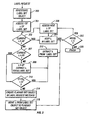
- FIG. 3 is a flowchart of the operation of one embodiment of the present invention.
- step 300 when a Label Request signaling message arrives at a node, the OSC at the node investigates the Label Set object thereof.
- step 301 the first wavelength of the Label Set object is accessed.
- step 302 a determination is made whether the wavelength is an element of the AP of the OSC. If so, execution proceeds to step 304, in which the wavelength is retained within the Label Set of the Label Set object and execution proceeds to step 305, in which the a determination is made whether there are any more wavelengths in the Label Set object. If so, execution proceeds to step 306, in which the next wavelength is accessed, and then returns to step 302.
- step 302 If in step 302 it is determined that the wavelength is not an element of the AP, execution proceeds to step 307, in which a determination is made whether the wavelength is an element of the FP. If not, execution proceeds to step 308, in which the wavelength is deemed to be an element of the UP and hence is extracted from the Label Set. If it is determined that the wavelength is an element of the FP, execution proceeds to step 310, in which a determination is made whether the clock time at the node minus the time stamp for the wavelength ("CT - TS ⁇ ") is less than a short threshold ("ST"). If so, indicating that the wavelength was fairly recently suggested, execution proceeds to step 312, in which the wavelength is extracted from the Label Set; otherwise, execution proceeds to step 314. In step 314, a Flagged Set object, if not already existent, is created within the Label Request message. In step 316, the wavelength is extracted from the Label Set and included in the Flagged Set of the Flagged Set object. Execution then returns to step 305.
- step 307 in
- step 305 If in step 305 it is determined that there are no more wavelengths in the Label Set object, execution proceeds to step 320, in which the reservation procedure is finished for the node.
- each Flagged Set may include each wavelength for which the current clock time (“CT") minus the time stamp of the wavelength (“TS ⁇ ”) falls within the time interval assigned to the Flagged Set.
- CT current clock time
- TS ⁇ time stamp of the wavelength
- N is the number of Flagged Sets
- ET is the Expiration Threshold at the node
- ST is the Short Threshold at the node
- CT is the current clock time at the node
- TS ⁇ is the time stamp of the wavelength at the node.
- the Flagged Sets are prioritized with reference to the time interval assigned thereto, with the Flagged Set whose time interval is closest to ET being the highest priority and the Flagged Set whose time interval is closest to ST being the lowest priority.
- the Flagged Sets are prioritized in order of decreasing n; as n increases, priority decreases.
- each wavelength will be analyzed as described above with reference to wavelengths of the Label Set, with the wavelength being removed from the Flagged Set if the wavelength is an element of the UP and being moved to a lower priority Flagged Set (e.g., Flagged Set-2) if the wavelength is an element of the FP and the (CT - TS ⁇ ) for the wavelengths falls into the time interval assigned to the lower priority Flagged Set.
- the highest priority Flagged Set e.g., Flagged Set-1
- each wavelength will be analyzed as described above with reference to wavelengths of the Label Set, with the wavelength being removed from the Flagged Set if the wavelength is an element of the UP and being moved to a lower priority Flagged Set (e.g., Flagged Set-2) if the wavelength is an element of the FP and the (CT - TS ⁇ ) for the wavelengths falls into the time interval assigned to the lower priority Flagged Set.
- FIG. 4 illustrates the format of an exemplary Flagged Set object 400 in accordance with one embodiment. It will be recognized by those of ordinary skill in the art that the format of the Flagged Set object 400 is similar to that of the Label Set object (not shown).
- An Action field 402 is one bit in length.
- a Reserved field 404 is currently not used and is 15 bits in length.
- a Label Type field 406 is two bytes in length. Specific wavelengths can be added to the Flagged Set by placing a 0 in the Action field 402. A range of wavelengths can be added to the Flagged Set by placing a 1 in the Action field 402. The absence of any wavelengths in wavelength fields 408 implies that there is no critically-suggested wavelengths.
- the Label Type field 406 indicates the priority of the Flagged Set object.
- one or more currently unused fields of the Label Set object could be used to designate the object as either a Label Set or a Flagged Set object, as well as to indicate the relative priorities of multiple Flagged Set objects.
- Each downstream node may change, or update, the set (i.e., Label Set or Flagged Set) to which any wavelength is assigned unidirectionally in decreasing order of priority; for example, a wavelength can be moved from the Label Set (higher priority) to a Flagged Set (lower priority), but not from a Flagged Set (lower priority) to the Label Set (higher priority).
- a wavelength can be moved from a higher priority Flagged Set (e.g., Flagged Set-1) to a lower priority Flagged Set (e.g., Flagged Set-2), but not vice versa.
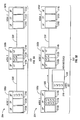
- FIGs. 5A-5C collectively illustrate an example of the teachings described hereinabove.
- the example will be described with reference to three nodes 500a, 500b, and 500c, along a path 502 in an optical network 504.
- Node 500a is the ingress, or source, node and node 500c is the egress, or destination, node.
- Nodes 500a and 500b are connected by a first link 506; nodes 500b and 500c are connected by a second link 508.
- Each link 506, 508, has four wavelengths ⁇ 1, ⁇ 2, ⁇ 3, and ⁇ 4.
- Each node 500a, 500b, 500c includes a UP 510a, 510b, 510c, respectively, an FP 512a, 512b, 512c, respectively, and an AP 514a, 514b, 514c, respectively.
- a first Flagged Set (“FS0” includes the wavelengths for which CT-TS ⁇ is between 2.0 seconds and 1.0 seconds
- FS1 includes the wavelengths for which CT-TS ⁇ is between 1.0 seconds and 0.0 seconds.
- wavelengths at the node 500a are in the AP 514a.
- the wavelength ⁇ 1 is already in use and hence is in the UP 510b.
- Wavelengths ⁇ 2 and ⁇ 4 have been suggested to different LSPs at local time stamps t2 and t4, respectively, and hence are in the FP 512b.
- Wavelength ⁇ 3 is available and hence is in the AP 514b.
- the node 500a places all four wavelengths ⁇ 1- ⁇ 4 into a Label Set 516 of a Label Request, in this case, a Path message 518, in order to set up the light path, and moves all of the wavelengths ⁇ 1- ⁇ 4 from the AP 514a to the FP 512a with a time stamp of t1, which indicates the local clock time at the time the wavelengths are placed in the Label Set.
- the Path message 518 is sent along the link 506 to the node 500b.
- the local clock time at the node 500b upon the arrival of the Path message 518 is c2.
- An OSC (not shown) at the node 500b takes the following actions. First, since ⁇ 1 is in the UP 510b, it is extracted from the Label Set 516. For the wavelength ⁇ 2, if 1.0 ⁇ (c2-t2) ⁇ 2.0, a Flagged Set-1 object 522 is created and the wavelength ⁇ 2 is moved from the Label Set object 516 to the Flagged Set-1 object 522.
- the wavelength ⁇ 3 Since the wavelength ⁇ 3 is in the AP 514b, it is retained in the Label Set 516. With respect to the wavelength ⁇ 4, if 1.0 ⁇ (c2-t4) ⁇ 2.0, then the wavelength ⁇ 4 is moved from the Label Set object 516 to the Flagged Set-1 object 522; however, if 0.0 ⁇ (c2-t4) ⁇ 1.0, then the wavelength ⁇ 4 is moved from the Label Set object 516 to the Flagged Set-2 object 524. It will be assumed that 0.0 ⁇ (c2-t4) ⁇ 1.0, so the wavelength ⁇ 4 is moved to the Flagged Set-2 object 524.
- the updated Path message 518 is then forwarded to the egress node 500c, which selects the wavelength ⁇ 3 from the Label Set object 516 for the LSP. If the Label Set 516 had been empty, the node 500c would have selected a wavelength from the Flagged Set-1 object 522. Similarly, if the both the Label Set object 516 and Flagged Set-1 object 522 had been empty, the node 500c would have selected a wavelength from the Flagged Set-2 object 524. It will be noted that if all of the objects 516, 522, and 524 were empty, an error message would be generated in the usual fashion.
- the embodiments described herein take into account the fact that the wavelength ⁇ 3, having not been recently suggested for use in another LSP along the path, is a preferable choice to the wavelengths ⁇ 2 and ⁇ 4, both of which have been more recently suggested than the wavelength ⁇ 3. Similarly, the wavelength ⁇ 2 is a preferable choice to ⁇ 4 due to the fact that the wavelength ⁇ 4 has been more recently suggested than the wavelength ⁇ 2.
- the present invention advantageously provides an innovative and efficient solution for facilitating fair and effective lightpath reservation in a GMPLS network.
- the invention provides a global label prioritization method that decreases the occurrence of wavelength collision in a GMPLS network.
Landscapes
- Engineering & Computer Science (AREA)
- Computer Networks & Wireless Communication (AREA)
- Signal Processing (AREA)
- Optical Communication System (AREA)
- Data Exchanges In Wide-Area Networks (AREA)
Abstract
Description
- The present invention generally relates to optical networks. More particularly, and not by way of any limitation, the present invention is directed to an optical switch controller for application in a Generalized Multi-Protocol Label Switching ("GMPLS") network for facilitating fair and effective reservation of lightpaths therein.
- In all-optical GMPLS wavelength division multiplex ("WDM") networks, lightpaths, or label switch paths ("LSPs"), may collide and fail during the lightpath establishment procedure. This is referred to as the wavelength collision problem. Shorter lightpaths have an advantage over longer lightpaths in reserving wavelengths.
FIG. 1 , which depicts a block diagram of an optical network 100, illustrates why this is the case. - In particular, assuming for the sake of example that an
LSP Request 1 requesting establishment of afirst lightpath 102 between asource node 103a and adestination node 103b, and anLSP Request 2 requesting establishment of asecond lightpath 104 between asource node 105a and adestination node 105b, are from their respective source nodes along their respective paths at the same time. Because thelightpath 104 is shorter,LSP Request 2 will be received at thedestination node 105b beforeLSP Request 1 is received at thedestination node 103b. Consequently, thelightpath 104 will be established first. - This may also be the case in a situation where the
LSP Request 1 is issued before theLSP Request 2, given thatlightpath 102 is significantly shorter thanlightpath 104. If bothlightpaths node 105b and appropriate error messages will be sent tonodes lightpath 102. - In existing protocols for lightpath reservation in GMPLS, an optical switch controller ("OSC") at each node in an optical network maintains two "pools" of wavelengths, including an "Available Pool" ("AP") and a "Used Pool" ("UP"). The AP includes wavelengths that available to be reserved by a lightpath. The UP comprises wavelengths that are currently being used by existing lightpaths.
- Currently, in the GMPLS signaling control plane (RSVP/LDP/CR-LDP), upstream nodes insert a "Label Set" object into each LSP Request (e.g., Path) message. The Label Set object suggests the labels (which correspond directly to wavelengths in the optical domain) that can be selected by the downstream nodes. In other words, the Label Set represents the wavelengths available for selection as indicated in the AP. Downstream nodes select one of the labels, or wavelengths, in the Label Set as specified in the Label Set object.
- In general, at each node along the path during LSP establishment, the OSC at the node compares the wavelengths of the Label Set object with those in its UP and removes from the Label Set object any common wavelengths. Similarly, once a wavelength has been reserved by a lightpath, the reserved wavelength is removed from the AP and included in the UP maintained by each node along the path.
- While the above-described technique certainly addresses the wavelength continuity problem, it fails to adequately address the short lightpath/long lightpath disparity described above with reference to
FIG. 1 . Moreover, it fails to solve the wavelength collision. In particular, it does not prevent the suggestion of the same wavelengths to, and the possible selection of the same wavelength by, more than one LSP. For example, referring again toFIG. 1 , assumingLSP Request 1 is issued at a time t1 andLSP Request 2 is issued at a time t2 after time t1. Assuming further thatLSP Request 2 is received at thenode 105b at a time t3 andLSP Request 1 is received at thenode 103b at a time t4 after time t3. IfLSP Request 1 is received at thenode 105b any time before time t3, the wavelength that will ultimately be assigned to thelightpath 104 will still be in the AP at that node; therefore, it is conceivable that the same wavelength will be assigned to bothpaths - Wavelength conversion may eliminate the wavelength collision problem; however, wavelength converters are expensive, rendering it impractical to include such equipment at every node in a network.
- The document WIDJAJA I ET AL: "Study of GMPLS lightpath setup over lambda-router networks", ICC 2002. 2002 IEEE INTERNATIONAL CONFERENCE ON COMMUNICATIONS. CONFERENCE PROCEEDINGS. NEW YORK, NY, APRIL 28 - MAY 2, 2002; vol. 5, 28 April 2002 (2002-04-28), pages 2707-2711, ISBN: 978-0-7803-7400-3, discloses a study of GMPLS Lightpath Setup over Lambda-Router Networks.
- The present invention comprises an optical switch controller ("OSC") for application in a Generalized Multi-Protocol Label Switching ("GMPLS") network for facilitating fair and effective reservation of lightpaths therein. In accordance with features of one embodiment, in addition to the UP and AP maintained at each node, an additional pool, designated a "Flagged Pool" ("FP"), is also maintained. The FP includes wavelengths that have been suggested but not yet reserved by a lightpath. As previously described, the UP includes wavelengths that are currently being used by LSPs. The AP includes wavelengths not included in the UP or the FP. Each wavelength included in the FP includes a time stamp indicating the local time at which the wavelength was suggested.
- At each node along the path during LSP establishment, a determination is made with respect to each wavelength of the Label Set object included in the Label Request (e.g., Path) message whether the wavelength is an element of the AP of the node. If not, a determination is made whether the wavelength is an element of the FP of the node. If the wavelength is an element of neither the AP nor the FP, and hence is an element of the UP, the wavelength is extracted from the Label Set. If the wavelength is an element of the FP, a determination is made whether the local clock time minus the time stamp for the wavelength is less than a first threshold. If so, the wavelength is extracted from the Label Set; otherwise, a Flagged Set is created (if not already existent) and the wavelength is extracted from the Label Set and placed in the Flagged Set.
For each wavelength of the FP, upon expiration of a predetermined time period without the wavelength being reserved, the wavelength is returned to the AP. - In one aspect, the invention comprises a method of implementing an optical switch controller ("OSC") at a node of an optical network comprising the steps of, responsive to receipt at the node of a Label Request message identifying a Label Set comprising a plurality of wavelengths, for each wavelength of the Label Set: (1) determining whether the wavelength is an element of an Available Pool ("AP") of the OSC; (2) responsive to a determination that the wavelength is not an element of the AP, determining whether the wavelength is an element of a Flagged Pool ("FP") of the OSC; (3) responsive to a determination that the wavelength is not an element of the FP, updating the Label Request message by removing the wavelength from the Label Set; (4) responsive to a determination that the wavelength is an element of the FP, determining whether a local clock time at the node minus a time stamp associated with the wavelength in the FP is less than a short threshold; (5) responsive to a determination that the local clock time at the node minus the time stamp associated with the wavelength is shorter than a short threshold, updating the Label Request message by removing the wavelength from the Label Set; and (6) responsive to a determination that the local clock time at the node minus the time stamp associated with the wavelength is not shorter than a short threshold, updating the Label Request message by removing the wavelength from the Label Set and including the wavelength in a Flagged Set identified in the Label Request message.
- In another aspect, the invention comprises an optical switch controller ("OSC") in a node of an optical network comprising a Used Pool ("UP") comprising a list of wavelengths currently in use for existing optical paths through the node, a Flagged Pool ("FP") identifying wavelengths proposed for new optical paths to be established through the node and including for each identified wavelength a time stamp indicating when the wavelength was proposed, and an Available Pool ("AP") identifying wavelengths that are not elements of the UP or the FP.
- In another aspect, the invention comprises an optical switch controller ("OSC") at a node of an optical network comprising means responsive to receipt at the node of a Label Request message identifying a Label Set for determining whether a wavelength of the Label Set is an element of an Available Pool ("AP") of the OSC, means responsive to a determination that the wavelength is not an element of the AP for determining whether the wavelength is an element of a Flagged Pool ("FP") of the OSC, means responsive to a determination that the wavelength is not an element of the FP for updating the Label Request message by removing the wavelength from the Label Set, means responsive to a determination that the wavelength is an element of the FP for determining whether a local clock time at the node minus a time stamp associated with the wavelength in the FP is less than a short threshold, means responsive to a determination that the local clock time at the node minus the time stamp associated with the wavelength is shorter than a short threshold for updating the Label Request message by removing the wavelength from the Label Set, and means responsive to a determination that the local clock time at the node minus the time stamp associated with the wavelength is not shorter than a short threshold for updating the Label Request message by removing the wavelength from the Label Set and including the wavelength in a Flagged Set identified in the Label Request message.
- A more complete understanding of the present invention may be had by reference to the following Detailed Description when taken in conjunction with the accompanying drawings wherein:
-
FIG. 1 is a system block diagram illustrating a wavelength collision problem inherent in prior art methods of assigning a wavelength to a flow in an optical network; -
FIG. 2 is a system block diagram of an optical switch controller ("OSC") in accordance with one embodiment of the present invention; -
FIG. 3 is a flowchart illustrating operation of the OSC ofFIG. 2 in accordance with one embodiment of the present invention; -
FIG. 4 depicts the format of a Flagged Set object for use in connection with one embodiment of the present invention; and -
FIGs. 5A-5C collectively illustrate an exemplary application of one embodiment of the present invention. - In the drawings, like or similar elements are designated with identical reference numerals throughout the several views thereof, and the various elements depicted are not necessarily drawn to scale.
-
FIG. 2 is a block diagram of anOSC 200 in accordance with one embodiment of the present invention. The OSC 200, which is located at an optical switch/router, or node, 201, of an optical network, includes three pools; specifically, a Used Pool ("UP") 202, a Flagged Pool ("FP") 204, and an Available Pool ("AP") 206. It will be recognized that the UP, FP, and AP are stored as tables in a database of the OSC 200. - As will be recognized by one of ordinary skill in the art, and as partially illustrated in
FIG. 2 , during establishment of an LSP, a Label Request message, such as an RSVP Path message, that includes a Label Set object suggesting wavelengths that may be reserved for use by the LSP, from a source node (not shown) is forwarded to thenode 201 from an upstream node (not shown) and subsequently forwarded to a downstream node (not shown). This process continues until the Label Request message reaches a destination node (not shown), which selects a wavelength from the Label Set. A Label Selection message, such as an RSVP Resv message, that identifies the selected wavelength that has been reserved for the LSP, from the destination node is forwarded from the downstream node to thenode 201 and from thenode 201 to the upstream node and back to the source node (not shown) to complete the LSP establishment process. - As previously described, the
UP 202 includes the wavelengths that are currently being used by existing LSPs that include thenode 201. TheFP 204 includes wavelengths that have been suggested but not yet reserved. TheAP 206 includes all of the remaining wavelengths. In the example illustrated inFIG. 2 , theUP 202 includes one wavelength λ1, theFP 204 includes one wavelength λ2, and theAP 206 includes two wavelengths λ3 and λ4. - The
FP 204 includes a time stamp for each wavelength indicating when the wavelength was last suggested; i.e., included in a Label Set object. For each wavelength of theFP 204, upon expiration of a predetermined Expiration Threshold ("ET") without the wavelength being selected, as determined by taking the local clock time less the time stamp for the wavelength, the wavelength is moved from theFP 204 to theAP 206. The ET can be adaptive or dynamic and selected to be the maximum or average LSP set up time. The ET may be established and maintained on a node-by-node basis; therefore, the ET at thenode 201 may be different than the ET at other nodes. Because the local clock time at the node is used in preparing the time stamp and subsequently determining whether the ET has expired, no synchronization among nodes is necessary. -
FIG. 3 is a flowchart of the operation of one embodiment of the present invention. Instep 300, when a Label Request signaling message arrives at a node, the OSC at the node investigates the Label Set object thereof. Instep 301, the first wavelength of the Label Set object is accessed. Instep 302, a determination is made whether the wavelength is an element of the AP of the OSC. If so, execution proceeds to step 304, in which the wavelength is retained within the Label Set of the Label Set object and execution proceeds to step 305, in which the a determination is made whether there are any more wavelengths in the Label Set object. If so, execution proceeds to step 306, in which the next wavelength is accessed, and then returns to step 302. - If in
step 302 it is determined that the wavelength is not an element of the AP, execution proceeds to step 307, in which a determination is made whether the wavelength is an element of the FP. If not, execution proceeds to step 308, in which the wavelength is deemed to be an element of the UP and hence is extracted from the Label Set. If it is determined that the wavelength is an element of the FP, execution proceeds to step 310, in which a determination is made whether the clock time at the node minus the time stamp for the wavelength ("CT - TSλ") is less than a short threshold ("ST"). If so, indicating that the wavelength was fairly recently suggested, execution proceeds to step 312, in which the wavelength is extracted from the Label Set; otherwise, execution proceeds to step 314. Instep 314, a Flagged Set object, if not already existent, is created within the Label Request message. Instep 316, the wavelength is extracted from the Label Set and included in the Flagged Set of the Flagged Set object. Execution then returns to step 305. - If in
step 305 it is determined that there are no more wavelengths in the Label Set object, execution proceeds to step 320, in which the reservation procedure is finished for the node. - In an alternative embodiment, more than one Flagged Set, and corresponding Flagged Set objects, may be employed. Assuming that N Flagged Sets are created, a different one of N time intervals will be assigned to each of the Flagged Sets. Accordingly, each Flagged Set will include each wavelength for which the current clock time ("CT") minus the time stamp of the wavelength ("TSλ") falls within the time interval assigned to the Flagged Set.
- In particular, in a situation where there are N Flagged Sets, the time interval assigned to an nth Flagged Set, for n=1 to N is:

- For example, assuming ET is equal to 8 seconds, ST is equal to 4 seconds and N equals 2, then a first Flagged Set (n=1) will include all wavelengths for which the current clock time at the node minus the time stamp of the wavelength (CT-TSλ) is between 8 seconds and 6 seconds and a second Flagged Set (n=2) will include all wavelengths for which (CT - TSλ) is between 6 seconds and 4 seconds.
- It should be noted that, regardless of the number of Flagged Sets that are implemented, a similar process as that described above in connection with the Label Set (as illustrated in
FIG. 3 ) will be performed for each of the Flagged Sets in decreasing order of priority. In particular, starting with the highest priority Flagged Set (e.g., Flagged Set-1), each wavelength will be analyzed as described above with reference to wavelengths of the Label Set, with the wavelength being removed from the Flagged Set if the wavelength is an element of the UP and being moved to a lower priority Flagged Set (e.g., Flagged Set-2) if the wavelength is an element of the FP and the (CT - TSλ) for the wavelengths falls into the time interval assigned to the lower priority Flagged Set. -
FIG. 4 illustrates the format of an exemplaryFlagged Set object 400 in accordance with one embodiment. It will be recognized by those of ordinary skill in the art that the format of theFlagged Set object 400 is similar to that of the Label Set object (not shown). AnAction field 402 is one bit in length. AReserved field 404 is currently not used and is 15 bits in length. ALabel Type field 406 is two bytes in length. Specific wavelengths can be added to the Flagged Set by placing a 0 in theAction field 402. A range of wavelengths can be added to the Flagged Set by placing a 1 in theAction field 402. The absence of any wavelengths inwavelength fields 408 implies that there is no critically-suggested wavelengths. TheLabel Type field 406 indicates the priority of the Flagged Set object. - Alternatively, rather than using separate Flagged Set objects, one or more currently unused fields of the Label Set object could be used to designate the object as either a Label Set or a Flagged Set object, as well as to indicate the relative priorities of multiple Flagged Set objects.
- Each downstream node may change, or update, the set (i.e., Label Set or Flagged Set) to which any wavelength is assigned unidirectionally in decreasing order of priority; for example, a wavelength can be moved from the Label Set (higher priority) to a Flagged Set (lower priority), but not from a Flagged Set (lower priority) to the Label Set (higher priority). Similarly, in situations in which multiple Flagged Sets exist, a wavelength can be moved from a higher priority Flagged Set (e.g., Flagged Set-1) to a lower priority Flagged Set (e.g., Flagged Set-2), but not vice versa.
-
FIGs. 5A-5C collectively illustrate an example of the teachings described hereinabove. The example will be described with reference to threenodes path 502 in anoptical network 504.Node 500a is the ingress, or source, node and node 500c is the egress, or destination, node.Nodes first link 506;nodes 500b and 500c are connected by asecond link 508. Eachlink node UP FP AP - Referring to
FIG. 5A , initially, all of the wavelengths at thenode 500a are in theAP 514a. At thenode 500b, the wavelength λ1 is already in use and hence is in theUP 510b. Wavelengths λ2 and λ4 have been suggested to different LSPs at local time stamps t2 and t4, respectively, and hence are in theFP 512b. Wavelength λ3 is available and hence is in theAP 514b. Moving on toFIG. 5B , thenode 500a places all four wavelengths λ1- λ4 into aLabel Set 516 of a Label Request, in this case, aPath message 518, in order to set up the light path, and moves all of the wavelengths λ1- λ4 from theAP 514a to theFP 512a with a time stamp of t1, which indicates the local clock time at the time the wavelengths are placed in the Label Set. ThePath message 518 is sent along thelink 506 to thenode 500b. - Referring now to
FIG. 5C , it will be assumed that the local clock time at thenode 500b upon the arrival of thePath message 518 is c2. An OSC (not shown) at thenode 500b takes the following actions. First, since λ1 is in theUP 510b, it is extracted from theLabel Set 516. For the wavelength λ2, if 1.0 < (c2-t2) < 2.0, a Flagged Set-1object 522 is created and the wavelength λ2 is moved from the Label Set object 516 to the Flagged Set-1object 522. On the other hand, if 0.0 < (c2-t2) < 1.0, a Flagged Set-2object 524 is created and the wavelength λ2 is moved from the Label Set object 516 to the Flagged Set-2object 524. It will be assumed for the sake of example that 1.0 < (c2-t2) < 2.0, so the wavelength λ2 is moved from the Label Set object 516 to the Flagged Set-1object 522. - Since the wavelength λ3 is in the
AP 514b, it is retained in theLabel Set 516. With respect to the wavelength λ4, if 1.0 < (c2-t4) < 2.0, then the wavelength λ4 is moved from the Label Set object 516 to the Flagged Set-1object 522; however, if 0.0 < (c2-t4) < 1.0, then the wavelength λ4 is moved from the Label Set object 516 to the Flagged Set-2object 524. It will be assumed that 0.0 < (c2-t4) < 1.0, so the wavelength λ4 is moved to the Flagged Set-2object 524. - The updated
Path message 518 is then forwarded to the egress node 500c, which selects the wavelength λ3 from the Label Set object 516 for the LSP. If theLabel Set 516 had been empty, the node 500c would have selected a wavelength from the Flagged Set-1object 522. Similarly, if the both theLabel Set object 516 and Flagged Set-1object 522 had been empty, the node 500c would have selected a wavelength from the Flagged Set-2object 524. It will be noted that if all of theobjects
Under current GMPLS standards, all three of the wavelengths λ2, λ3, and λ4 would be included in the Label Set object 516 and the node 500c would select one of these wavelengths. In contrast, the embodiments described herein take into account the fact that the wavelength λ3, having not been recently suggested for use in another LSP along the path, is a preferable choice to the wavelengths λ2 and λ4, both of which have been more recently suggested than the wavelength λ3. Similarly, the wavelength λ2 is a preferable choice to λ4 due to the fact that the wavelength λ4 has been more recently suggested than the wavelength λ2. - Based upon the foregoing Detailed Description, it should be readily apparent that the present invention advantageously provides an innovative and efficient solution for facilitating fair and effective lightpath reservation in a GMPLS network. In particular, without requiring global timing, global time stamps, or node synchronization, using just local node clocks and local time stamps, the invention provides a global label prioritization method that decreases the occurrence of wavelength collision in a GMPLS network.
- It is believed that the operation and construction of the present invention will be apparent from the foregoing Detailed Description. While the exemplary embodiments of the invention shown and described have been characterized as being preferred, it should be readily understood that various changes and modifications could be made therein without departing from the scope of the present invention as set forth in the following claims.
Claims (10)
- A method of implementing an optical switch controller (200) at a node (201) of an optical network, the method comprising the steps of: responsive to receipt at the node (201) of a Label Request message (518) identifying a Label Set (516) comprising a plurality of wavelengths, for one or more wavelengths of the Label Set (516); determining (307) whether the wavelength is an element of a Flagged Pool (204) of the optical switch controller (200), wherein the Flagged Pool (204) identifies wavelengths proposed for new optical paths to be established through the node (201); when the wavelength is an element of the Flagged Pool (204), determining (310) whether a local clock time (CT) at the node (201) minus a time stamp (TSλ) associated with the wavelength in the Flagged Pool (204) is less than a short threshold (ST); when the local clock time (CT) at the node (201) minus the time stamp (TSλ) associated with the wavelength is shorter than a short threshold (ST), removing the wavelength from the Label Set.
- The method of claim 1 further comprising: when the local clock time at the node (201) minus the time stamp associated with the wavelength is not shorter than a short threshold, updating the Label Request message (518) by removing the wavelength from the Label Set and including the wavelength in a Flagged Set identified in the Label Request; when the wavelength is an element of a Used Pool (202), removing the wavelength from the Label Set; and forwarding the updated Label Request message to a downstream node.
- The method of claim 1 wherein the optical network is a Generalized Multi-Protocol Label Switching network.
- The method of claim 1 further comprising the steps of: identifying in the Label Request message more than one Flagged Set; and assigning a different time interval to each of the Flagged Sets.
- An optical switch controller (200) in a node (201) of an optical network comprising: a Used Pool (202) comprising a list of wavelengths currently in use for existing optical paths through the node (201); a Flagged Pool (204) identifying wavelengths proposed for new optical paths to be established through the node (201) and including for each identified wavelength a time stamp indicating when the wavelength was proposed; and an Available Pool (206) identifying wavelengths that are not elements of the Used Pool (202) or the Flagged Pool (204).
- The optical switch controller (200) of claim 5, wherein responsive to receipt at the node (201) of a Label Request message (518) identifying a Label Set comprising a plurality of wavelengths, for each wavelength of the Label Set, the optical switch controller (200): updates the Label Request message (518) by removing the wavelength from the Label Set if the wavelength is an element of the Used Pool (202) of the node (201); updates the Label Request message (518) by removing the wavelength from the Label Set and including the wavelength in a Flagged Set identified in the Label Request message if the wavelength is an element of the Flagged Pool (204) of the node (201) and the local clock time at the node (201) minus the time stamp associated with the wavelength is not shorter than a short threshold; and updates the Label Request message (518) by removing the wavelength from the Label Set if the wavelength is an element of the Flagged Pool (204) of the node (201) and the local clock time at the node (201) minus the time stamp associated with the wavelength is shorter than a short threshold.
- An optical switch controller (200) of claim 5, wherein the optical switch controller (200) comprises: means responsive to receipt at the node (201) of a Label Request message (518) identifying a Label Set for determining whether a wavelength of the Label Set is an element of the Available Pool (206) of the optical switch controller (200); means responsive to a determination that the wavelength is not an element of the Available Pool (206) for determining whether the wavelength is an element of the a Flagged Pool (204) of the optical switch controller (200); means responsive to a determination that the wavelength is not an element of the Flagged Pool (204) for updating the Label Request message (518) by removing the wavelength from the Label Set; means responsive to a determination that the wavelength is an element of the Flagged Pool (204) for determining whether a local clock time at the node (201) minus a time stamp associated with the wavelength in the Flagged Pool (204) is less than a short threshold; means responsive to a determination that the local clock time at the node (201) minus the time stamp associated with the wavelength is shorter than a short threshold for updating the Label Request message (518) by removing the wavelength from the Label Set; and means responsive to a determination that the local clock time at the node (201) minus the time stamp associated with the wavelength is not shorter than a short threshold for updating the Label Request message (518) by removing the wavelength from the Label Set and including the wavelength in a Flagged Set identified in the Label Request message (518).
- The optical switch controller (200) of claim 7 further comprising: means for identifying in the Label Request message (518) more than one Flagged Set; and means for assigning a different time interval to each of the Flagged Sets.
- The optical switch controller (200) of claim 8 further comprising: means for determining whether the current clock time at the node (201) minus the time stamp associated with the wavelength falls within the time interval assigned to one of the Flagged Sets; and means responsive to a determination that the current clock time at the node (201) minus the time stamp associated with the wavelength falls within the time interval assigned to one of the Flagged Sets for updating the Label Request message (518) by removing the wavelength from the Label Set and including the wavelength in the one of the Flagged Sets.
- The optical switch controller (200) of claim 9 wherein the Flagged Sets are prioritized such that a highest priority Flagged Set includes wavelengths for which a current clock time at the node (201) minus the time stamp associated with the wavelength is closer to an expiration threshold than to zero and a lowest priority Flagged Set includes wavelengths for which a current clock time at the node (201) minus the time stamp associated with the wavelength is closer to zero than to an expiration threshold.
Applications Claiming Priority (2)
| Application Number | Priority Date | Filing Date | Title |
|---|---|---|---|
| US163962 | 1998-09-30 | ||
| US10/163,962 US7171120B2 (en) | 2002-06-05 | 2002-06-05 | Optical switch controller for fair and effective lightpath reservation in an optical network |
Publications (3)
| Publication Number | Publication Date |
|---|---|
| EP1370108A2 EP1370108A2 (en) | 2003-12-10 |
| EP1370108A3 EP1370108A3 (en) | 2008-11-05 |
| EP1370108B1 true EP1370108B1 (en) | 2012-03-21 |
Family
ID=29549334
Family Applications (1)
| Application Number | Title | Priority Date | Filing Date |
|---|---|---|---|
| EP03012382A Expired - Lifetime EP1370108B1 (en) | 2002-06-05 | 2003-05-30 | Optical switch controller for fair and effective lightpath reservation in an optical network |
Country Status (3)
| Country | Link |
|---|---|
| US (1) | US7171120B2 (en) |
| EP (1) | EP1370108B1 (en) |
| AT (1) | ATE550882T1 (en) |
Families Citing this family (9)
| Publication number | Priority date | Publication date | Assignee | Title |
|---|---|---|---|---|
| US20040076151A1 (en) * | 2002-10-21 | 2004-04-22 | Walter Fant | Connection identifiers and restoration in optical networks |
| JP4062071B2 (en) * | 2002-11-26 | 2008-03-19 | 日本電気株式会社 | GMPLS label management device |
| CN100477628C (en) * | 2003-05-16 | 2009-04-08 | 富士通株式会社 | Method for setting up path in communication network communicating through layers, and communication device thereof |
| US20050030951A1 (en) * | 2003-08-06 | 2005-02-10 | Christian Maciocco | Reservation protocol signaling extensions for optical switched networks |
| US20050068968A1 (en) * | 2003-09-30 | 2005-03-31 | Shlomo Ovadia | Optical-switched (OS) network to OS network routing using extended border gateway protocol |
| IES20040413A2 (en) * | 2004-06-18 | 2005-12-29 | Intune Technologies Ltd | Method and system for a distributed wavelength (lambda) routed (dlr) network |
| CN1816217B (en) * | 2005-02-06 | 2010-06-02 | 华为技术有限公司 | Path Establishment Method Based on Node Address Replacement |
| FR2933255B1 (en) * | 2008-06-30 | 2012-09-28 | Alcatel Lucent | GENERATING A WAVELENGTH ALLOCATION OFFER FOR A CONNECTION |
| CN101605283B (en) * | 2009-06-29 | 2012-06-06 | 中兴通讯股份有限公司 | Method and device for recovering node resource state in WSON |
Family Cites Families (2)
| Publication number | Priority date | Publication date | Assignee | Title |
|---|---|---|---|---|
| US6600581B1 (en) * | 1999-08-31 | 2003-07-29 | Lucent Technologies Inc. | Connection verification in optical cross-connect arrangements |
| JP4316822B2 (en) * | 2001-05-18 | 2009-08-19 | 富士通株式会社 | Method for changing path path and switch device using the same |
-
2002
- 2002-06-05 US US10/163,962 patent/US7171120B2/en not_active Expired - Lifetime
-
2003
- 2003-05-30 EP EP03012382A patent/EP1370108B1/en not_active Expired - Lifetime
- 2003-05-30 AT AT03012382T patent/ATE550882T1/en active
Also Published As
| Publication number | Publication date |
|---|---|
| US7171120B2 (en) | 2007-01-30 |
| ATE550882T1 (en) | 2012-04-15 |
| EP1370108A2 (en) | 2003-12-10 |
| EP1370108A3 (en) | 2008-11-05 |
| US20040247315A1 (en) | 2004-12-09 |
Similar Documents
| Publication | Publication Date | Title |
|---|---|---|
| KR100798018B1 (en) | Precise reservation establishment method, switching device and machine-readable medium of optical path | |
| US7113481B2 (en) | Informed dynamic path protection for optical networks | |
| Zang et al. | Dynamic lightpath establishment in wavelength routed WDM networks | |
| US7289437B2 (en) | System and method for routing stability-based integrated traffic engineering for GMPLS optical networks | |
| JP4374307B2 (en) | Label switch path routing control method | |
| EP1579727B1 (en) | Method and apparatus for data and control packet scheduling in wdm photonic burst-switched networks | |
| US7372870B2 (en) | Ethernet transmission apparatus with a quick protective and fair attribute and its method | |
| US20040120705A1 (en) | Differentiated resilience in optical networks | |
| US20050063701A1 (en) | Method and system to recover resources in the event of data burst loss within WDM-based optical-switched networks | |
| EP2151959A1 (en) | Communication network system, path calculation device, and communication path establishment control method | |
| US7633938B2 (en) | Transfer system | |
| US8233487B2 (en) | Communication network system that establishes communication path by transferring control signal | |
| EP1370108A2 (en) | Optical switch controller for fair and effective lightpath reservation in an optical network | |
| EP1351540A2 (en) | Upstream resource management propagation system and method for use in bufferless networks | |
| Giorgetti et al. | Label preference schemes for lightpath provisioning and restoration in distributed GMPLS networks | |
| US7233743B2 (en) | Lightpath segmentation system and method in a generalized multi-protocol label switching network | |
| Sambo et al. | A contention detection scheme for lightpath restoration in GMPLS networks | |
| Dong et al. | Differentiated-resilience provisioning for the wavelength-routed optical network | |
| Pedroso et al. | An interoperable GMPLS/OBS Control Plane: RSVP and OSPF extensions proposal | |
| US20050135272A1 (en) | Method for setting up a logical connection between non-adjacent initial and final nodes in a telecommunications network | |
| JP2002261803A (en) | Label switching path setting method | |
| Mu? oz et al. | Experimental GMPLS-based provisioning for future all-optical DPRing-based MAN | |
| US8223763B2 (en) | Node device and label management method in optical transmission network | |
| Muñoz et al. | Flooding global wavelength information through GMPLS RSVP-TE signaling in unidirectional ring-based networks | |
| JP3777185B2 (en) | GMPLS + IP / MPLS network and nodes |
Legal Events
| Date | Code | Title | Description |
|---|---|---|---|
| PUAI | Public reference made under article 153(3) epc to a published international application that has entered the european phase |
Free format text: ORIGINAL CODE: 0009012 |
|
| AK | Designated contracting states |
Kind code of ref document: A2 Designated state(s): AT BE BG CH CY CZ DE DK EE ES FI FR GB GR HU IE IT LI LU MC NL PT RO SE SI SK TR |
|
| AX | Request for extension of the european patent |
Extension state: AL LT LV MK |
|
| RIN1 | Information on inventor provided before grant (corrected) |
Inventor name: VERCHERE, DOMINIQUE Inventor name: OZUGUR, TIMUCIN |
|
| RIN1 | Information on inventor provided before grant (corrected) |
Inventor name: OZUGUR, TIMUCIN Inventor name: VERCHERE, DOMINIQUE |
|
| RAP1 | Party data changed (applicant data changed or rights of an application transferred) |
Owner name: ALCATEL LUCENT |
|
| PUAL | Search report despatched |
Free format text: ORIGINAL CODE: 0009013 |
|
| AK | Designated contracting states |
Kind code of ref document: A3 Designated state(s): AT BE BG CH CY CZ DE DK EE ES FI FR GB GR HU IE IT LI LU MC NL PT RO SE SI SK TR |
|
| AX | Request for extension of the european patent |
Extension state: AL LT LV MK |
|
| 17P | Request for examination filed |
Effective date: 20090504 |
|
| AKX | Designation fees paid |
Designated state(s): AT BE BG CH CY CZ DE DK EE ES FI FR GB GR HU IE IT LI LU MC NL PT RO SE SI SK TR |
|
| 17Q | First examination report despatched |
Effective date: 20100624 |
|
| GRAP | Despatch of communication of intention to grant a patent |
Free format text: ORIGINAL CODE: EPIDOSNIGR1 |
|
| GRAS | Grant fee paid |
Free format text: ORIGINAL CODE: EPIDOSNIGR3 |
|
| GRAA | (expected) grant |
Free format text: ORIGINAL CODE: 0009210 |
|
| RAP1 | Party data changed (applicant data changed or rights of an application transferred) |
Owner name: ALCATEL LUCENT |
|
| AK | Designated contracting states |
Kind code of ref document: B1 Designated state(s): AT BE BG CH CY CZ DE DK EE ES FI FR GB GR HU IE IT LI LU MC NL PT RO SE SI SK TR |
|
| REG | Reference to a national code |
Ref country code: GB Ref legal event code: FG4D |
|
| REG | Reference to a national code |
Ref country code: CH Ref legal event code: EP |
|
| REG | Reference to a national code |
Ref country code: IE Ref legal event code: FG4D |
|
| REG | Reference to a national code |
Ref country code: AT Ref legal event code: REF Ref document number: 550882 Country of ref document: AT Kind code of ref document: T Effective date: 20120415 |
|
| REG | Reference to a national code |
Ref country code: DE Ref legal event code: R096 Ref document number: 60340311 Country of ref document: DE Effective date: 20120516 |
|
| REG | Reference to a national code |
Ref country code: NL Ref legal event code: VDEP Effective date: 20120321 |
|
| PG25 | Lapsed in a contracting state [announced via postgrant information from national office to epo] |
Ref country code: GR Free format text: LAPSE BECAUSE OF FAILURE TO SUBMIT A TRANSLATION OF THE DESCRIPTION OR TO PAY THE FEE WITHIN THE PRESCRIBED TIME-LIMIT Effective date: 20120622 Ref country code: FI Free format text: LAPSE BECAUSE OF FAILURE TO SUBMIT A TRANSLATION OF THE DESCRIPTION OR TO PAY THE FEE WITHIN THE PRESCRIBED TIME-LIMIT Effective date: 20120321 |
|
| REG | Reference to a national code |
Ref country code: AT Ref legal event code: MK05 Ref document number: 550882 Country of ref document: AT Kind code of ref document: T Effective date: 20120321 |
|
| PG25 | Lapsed in a contracting state [announced via postgrant information from national office to epo] |
Ref country code: CY Free format text: LAPSE BECAUSE OF FAILURE TO SUBMIT A TRANSLATION OF THE DESCRIPTION OR TO PAY THE FEE WITHIN THE PRESCRIBED TIME-LIMIT Effective date: 20120321 |
|
| PG25 | Lapsed in a contracting state [announced via postgrant information from national office to epo] |
Ref country code: SE Free format text: LAPSE BECAUSE OF FAILURE TO SUBMIT A TRANSLATION OF THE DESCRIPTION OR TO PAY THE FEE WITHIN THE PRESCRIBED TIME-LIMIT Effective date: 20120321 Ref country code: EE Free format text: LAPSE BECAUSE OF FAILURE TO SUBMIT A TRANSLATION OF THE DESCRIPTION OR TO PAY THE FEE WITHIN THE PRESCRIBED TIME-LIMIT Effective date: 20120321 Ref country code: CZ Free format text: LAPSE BECAUSE OF FAILURE TO SUBMIT A TRANSLATION OF THE DESCRIPTION OR TO PAY THE FEE WITHIN THE PRESCRIBED TIME-LIMIT Effective date: 20120321 Ref country code: BE Free format text: LAPSE BECAUSE OF FAILURE TO SUBMIT A TRANSLATION OF THE DESCRIPTION OR TO PAY THE FEE WITHIN THE PRESCRIBED TIME-LIMIT Effective date: 20120321 Ref country code: RO Free format text: LAPSE BECAUSE OF FAILURE TO SUBMIT A TRANSLATION OF THE DESCRIPTION OR TO PAY THE FEE WITHIN THE PRESCRIBED TIME-LIMIT Effective date: 20120321 Ref country code: SI Free format text: LAPSE BECAUSE OF FAILURE TO SUBMIT A TRANSLATION OF THE DESCRIPTION OR TO PAY THE FEE WITHIN THE PRESCRIBED TIME-LIMIT Effective date: 20120321 |
|
| PG25 | Lapsed in a contracting state [announced via postgrant information from national office to epo] |
Ref country code: SK Free format text: LAPSE BECAUSE OF FAILURE TO SUBMIT A TRANSLATION OF THE DESCRIPTION OR TO PAY THE FEE WITHIN THE PRESCRIBED TIME-LIMIT Effective date: 20120321 Ref country code: PT Free format text: LAPSE BECAUSE OF FAILURE TO SUBMIT A TRANSLATION OF THE DESCRIPTION OR TO PAY THE FEE WITHIN THE PRESCRIBED TIME-LIMIT Effective date: 20120723 |
|
| PG25 | Lapsed in a contracting state [announced via postgrant information from national office to epo] |
Ref country code: MC Free format text: LAPSE BECAUSE OF NON-PAYMENT OF DUE FEES Effective date: 20120531 |
|
| REG | Reference to a national code |
Ref country code: CH Ref legal event code: PL |
|
| PLBE | No opposition filed within time limit |
Free format text: ORIGINAL CODE: 0009261 |
|
| STAA | Information on the status of an ep patent application or granted ep patent |
Free format text: STATUS: NO OPPOSITION FILED WITHIN TIME LIMIT |
|
| PG25 | Lapsed in a contracting state [announced via postgrant information from national office to epo] |
Ref country code: CH Free format text: LAPSE BECAUSE OF NON-PAYMENT OF DUE FEES Effective date: 20120531 Ref country code: DK Free format text: LAPSE BECAUSE OF FAILURE TO SUBMIT A TRANSLATION OF THE DESCRIPTION OR TO PAY THE FEE WITHIN THE PRESCRIBED TIME-LIMIT Effective date: 20120321 Ref country code: AT Free format text: LAPSE BECAUSE OF FAILURE TO SUBMIT A TRANSLATION OF THE DESCRIPTION OR TO PAY THE FEE WITHIN THE PRESCRIBED TIME-LIMIT Effective date: 20120321 Ref country code: NL Free format text: LAPSE BECAUSE OF FAILURE TO SUBMIT A TRANSLATION OF THE DESCRIPTION OR TO PAY THE FEE WITHIN THE PRESCRIBED TIME-LIMIT Effective date: 20120321 Ref country code: LI Free format text: LAPSE BECAUSE OF NON-PAYMENT OF DUE FEES Effective date: 20120531 |
|
| 26N | No opposition filed |
Effective date: 20130102 |
|
| REG | Reference to a national code |
Ref country code: IE Ref legal event code: MM4A |
|
| PG25 | Lapsed in a contracting state [announced via postgrant information from national office to epo] |
Ref country code: IT Free format text: LAPSE BECAUSE OF FAILURE TO SUBMIT A TRANSLATION OF THE DESCRIPTION OR TO PAY THE FEE WITHIN THE PRESCRIBED TIME-LIMIT Effective date: 20120321 |
|
| REG | Reference to a national code |
Ref country code: DE Ref legal event code: R097 Ref document number: 60340311 Country of ref document: DE Effective date: 20130102 |
|
| PG25 | Lapsed in a contracting state [announced via postgrant information from national office to epo] |
Ref country code: IE Free format text: LAPSE BECAUSE OF NON-PAYMENT OF DUE FEES Effective date: 20120530 Ref country code: ES Free format text: LAPSE BECAUSE OF FAILURE TO SUBMIT A TRANSLATION OF THE DESCRIPTION OR TO PAY THE FEE WITHIN THE PRESCRIBED TIME-LIMIT Effective date: 20120702 |
|
| PG25 | Lapsed in a contracting state [announced via postgrant information from national office to epo] |
Ref country code: BG Free format text: LAPSE BECAUSE OF FAILURE TO SUBMIT A TRANSLATION OF THE DESCRIPTION OR TO PAY THE FEE WITHIN THE PRESCRIBED TIME-LIMIT Effective date: 20120621 |
|
| REG | Reference to a national code |
Ref country code: FR Ref legal event code: GC Effective date: 20131018 |
|
| PG25 | Lapsed in a contracting state [announced via postgrant information from national office to epo] |
Ref country code: TR Free format text: LAPSE BECAUSE OF FAILURE TO SUBMIT A TRANSLATION OF THE DESCRIPTION OR TO PAY THE FEE WITHIN THE PRESCRIBED TIME-LIMIT Effective date: 20120321 |
|
| PG25 | Lapsed in a contracting state [announced via postgrant information from national office to epo] |
Ref country code: LU Free format text: LAPSE BECAUSE OF NON-PAYMENT OF DUE FEES Effective date: 20120530 |
|
| PG25 | Lapsed in a contracting state [announced via postgrant information from national office to epo] |
Ref country code: HU Free format text: LAPSE BECAUSE OF FAILURE TO SUBMIT A TRANSLATION OF THE DESCRIPTION OR TO PAY THE FEE WITHIN THE PRESCRIBED TIME-LIMIT Effective date: 20030530 |
|
| REG | Reference to a national code |
Ref country code: FR Ref legal event code: RG Effective date: 20141016 |
|
| REG | Reference to a national code |
Ref country code: FR Ref legal event code: PLFP Year of fee payment: 13 |
|
| REG | Reference to a national code |
Ref country code: FR Ref legal event code: PLFP Year of fee payment: 14 |
|
| REG | Reference to a national code |
Ref country code: FR Ref legal event code: PLFP Year of fee payment: 15 |
|
| REG | Reference to a national code |
Ref country code: FR Ref legal event code: PLFP Year of fee payment: 16 |
|
| REG | Reference to a national code |
Ref country code: GB Ref legal event code: 732E Free format text: REGISTERED BETWEEN 20190429 AND 20190502 |
|
| REG | Reference to a national code |
Ref country code: DE Ref legal event code: R082 Ref document number: 60340311 Country of ref document: DE Representative=s name: MENZIETTI WETZEL, DE Ref country code: DE Ref legal event code: R081 Ref document number: 60340311 Country of ref document: DE Owner name: PROVENANCE ASSET GROUP LLC, PITTSFORD, US Free format text: FORMER OWNER: ALCATEL LUCENT, PARIS, FR |
|
| REG | Reference to a national code |
Ref country code: GB Ref legal event code: 732E Free format text: REGISTERED BETWEEN 20220210 AND 20220216 |
|
| PGFP | Annual fee paid to national office [announced via postgrant information from national office to epo] |
Ref country code: GB Payment date: 20220526 Year of fee payment: 20 Ref country code: FR Payment date: 20220520 Year of fee payment: 20 Ref country code: DE Payment date: 20220525 Year of fee payment: 20 |
|
| REG | Reference to a national code |
Ref country code: DE Ref legal event code: R071 Ref document number: 60340311 Country of ref document: DE |
|
| REG | Reference to a national code |
Ref country code: GB Ref legal event code: PE20 Expiry date: 20230529 |
|
| P01 | Opt-out of the competence of the unified patent court (upc) registered |
Effective date: 20230524 |
|
| PG25 | Lapsed in a contracting state [announced via postgrant information from national office to epo] |
Ref country code: GB Free format text: LAPSE BECAUSE OF EXPIRATION OF PROTECTION Effective date: 20230529 |