EP1369949A2 - Solid electrolyte fuel cell and manufacturing method thereof - Google Patents
Solid electrolyte fuel cell and manufacturing method thereof Download PDFInfo
- Publication number
- EP1369949A2 EP1369949A2 EP03012535A EP03012535A EP1369949A2 EP 1369949 A2 EP1369949 A2 EP 1369949A2 EP 03012535 A EP03012535 A EP 03012535A EP 03012535 A EP03012535 A EP 03012535A EP 1369949 A2 EP1369949 A2 EP 1369949A2
- Authority
- EP
- European Patent Office
- Prior art keywords
- solid electrolyte
- fuel cell
- electrolyte fuel
- electrodes
- set forth
- Prior art date
- Legal status (The legal status is an assumption and is not a legal conclusion. Google has not performed a legal analysis and makes no representation as to the accuracy of the status listed.)
- Granted
Links
Images




Classifications
-
- H—ELECTRICITY
- H01—ELECTRIC ELEMENTS
- H01M—PROCESSES OR MEANS, e.g. BATTERIES, FOR THE DIRECT CONVERSION OF CHEMICAL ENERGY INTO ELECTRICAL ENERGY
- H01M4/00—Electrodes
- H01M4/86—Inert electrodes with catalytic activity, e.g. for fuel cells
- H01M4/90—Selection of catalytic material
- H01M4/92—Metals of platinum group
-
- H—ELECTRICITY
- H01—ELECTRIC ELEMENTS
- H01M—PROCESSES OR MEANS, e.g. BATTERIES, FOR THE DIRECT CONVERSION OF CHEMICAL ENERGY INTO ELECTRICAL ENERGY
- H01M4/00—Electrodes
- H01M4/86—Inert electrodes with catalytic activity, e.g. for fuel cells
- H01M4/8605—Porous electrodes
-
- H—ELECTRICITY
- H01—ELECTRIC ELEMENTS
- H01M—PROCESSES OR MEANS, e.g. BATTERIES, FOR THE DIRECT CONVERSION OF CHEMICAL ENERGY INTO ELECTRICAL ENERGY
- H01M8/00—Fuel cells; Manufacture thereof
- H01M8/10—Fuel cells with solid electrolytes
- H01M8/12—Fuel cells with solid electrolytes operating at high temperature, e.g. with stabilised ZrO2 electrolyte
- H01M8/1213—Fuel cells with solid electrolytes operating at high temperature, e.g. with stabilised ZrO2 electrolyte characterised by the electrode/electrolyte combination or the supporting material
-
- H—ELECTRICITY
- H01—ELECTRIC ELEMENTS
- H01M—PROCESSES OR MEANS, e.g. BATTERIES, FOR THE DIRECT CONVERSION OF CHEMICAL ENERGY INTO ELECTRICAL ENERGY
- H01M8/00—Fuel cells; Manufacture thereof
- H01M8/10—Fuel cells with solid electrolytes
- H01M8/12—Fuel cells with solid electrolytes operating at high temperature, e.g. with stabilised ZrO2 electrolyte
- H01M8/124—Fuel cells with solid electrolytes operating at high temperature, e.g. with stabilised ZrO2 electrolyte characterised by the process of manufacturing or by the material of the electrolyte
- H01M8/1246—Fuel cells with solid electrolytes operating at high temperature, e.g. with stabilised ZrO2 electrolyte characterised by the process of manufacturing or by the material of the electrolyte the electrolyte consisting of oxides
- H01M8/1253—Fuel cells with solid electrolytes operating at high temperature, e.g. with stabilised ZrO2 electrolyte characterised by the process of manufacturing or by the material of the electrolyte the electrolyte consisting of oxides the electrolyte containing zirconium oxide
-
- H—ELECTRICITY
- H01—ELECTRIC ELEMENTS
- H01M—PROCESSES OR MEANS, e.g. BATTERIES, FOR THE DIRECT CONVERSION OF CHEMICAL ENERGY INTO ELECTRICAL ENERGY
- H01M8/00—Fuel cells; Manufacture thereof
- H01M8/10—Fuel cells with solid electrolytes
- H01M8/12—Fuel cells with solid electrolytes operating at high temperature, e.g. with stabilised ZrO2 electrolyte
- H01M8/124—Fuel cells with solid electrolytes operating at high temperature, e.g. with stabilised ZrO2 electrolyte characterised by the process of manufacturing or by the material of the electrolyte
- H01M8/1246—Fuel cells with solid electrolytes operating at high temperature, e.g. with stabilised ZrO2 electrolyte characterised by the process of manufacturing or by the material of the electrolyte the electrolyte consisting of oxides
- H01M8/126—Fuel cells with solid electrolytes operating at high temperature, e.g. with stabilised ZrO2 electrolyte characterised by the process of manufacturing or by the material of the electrolyte the electrolyte consisting of oxides the electrolyte containing cerium oxide
-
- Y—GENERAL TAGGING OF NEW TECHNOLOGICAL DEVELOPMENTS; GENERAL TAGGING OF CROSS-SECTIONAL TECHNOLOGIES SPANNING OVER SEVERAL SECTIONS OF THE IPC; TECHNICAL SUBJECTS COVERED BY FORMER USPC CROSS-REFERENCE ART COLLECTIONS [XRACs] AND DIGESTS
- Y02—TECHNOLOGIES OR APPLICATIONS FOR MITIGATION OR ADAPTATION AGAINST CLIMATE CHANGE
- Y02E—REDUCTION OF GREENHOUSE GAS [GHG] EMISSIONS, RELATED TO ENERGY GENERATION, TRANSMISSION OR DISTRIBUTION
- Y02E60/00—Enabling technologies; Technologies with a potential or indirect contribution to GHG emissions mitigation
- Y02E60/30—Hydrogen technology
- Y02E60/50—Fuel cells
-
- Y—GENERAL TAGGING OF NEW TECHNOLOGICAL DEVELOPMENTS; GENERAL TAGGING OF CROSS-SECTIONAL TECHNOLOGIES SPANNING OVER SEVERAL SECTIONS OF THE IPC; TECHNICAL SUBJECTS COVERED BY FORMER USPC CROSS-REFERENCE ART COLLECTIONS [XRACs] AND DIGESTS
- Y02—TECHNOLOGIES OR APPLICATIONS FOR MITIGATION OR ADAPTATION AGAINST CLIMATE CHANGE
- Y02P—CLIMATE CHANGE MITIGATION TECHNOLOGIES IN THE PRODUCTION OR PROCESSING OF GOODS
- Y02P70/00—Climate change mitigation technologies in the production process for final industrial or consumer products
- Y02P70/50—Manufacturing or production processes characterised by the final manufactured product
Definitions
- the present invention relates to a solid electrolyte fuel cell and a manufacturing method thereof.
- Fuel cells as power generators and devices that are clean and can save energy, have been advanced in developing stationary or mobile consumer power sources. Specifically, the fuel cells are attracting attention as household cogeneration power sources and power sources for use in electric cars.
- micro-fuel cell is attracting attention as portable power sources in place of secondary batteries.
- electrolyte membranes of this type NAFION membranes are under study.
- a fuel cell is a device into which, usually, gaseous fuels such as hydrogen and air are supplied and electricity is extracted.
- gaseous fuels such as hydrogen and air are supplied and electricity is extracted.
- direct methanol an easy-carrying liquid fuel called direct methanol is considered.
- a solid electrolyte fuel cell in which the electrolyte is a solid, is free from water; and since an entire fuel cell can be constituted without using a liquid, there are no problems of liquid leakage and liquid replenishment.
- the invention intends to provide a solid electrolyte fuel cell in which a cell output can be obtained even at temperatures lower than 500 degrees centigrade, materials that can be easily machined and are cheaper can be used as a separator and housing material, and a method of manufacturing the same.
- the invention is constituted as follows.
- a solid electrolyte fuel cell includes a pair of electrodes and a solid electrolyte disposed between the electrodes.
- the solid electrolyte is a protonic oxide conductor having a composition represented by, for instance, Ba (Zr 1-x Ce x ) 1-y M y Al z O 3- ⁇ (M: one or more kinds of elements selected from a group of tri-valent rare earth elements and In, 1 > x > 0, 0.3 > y > 0, 0.04 > z > 0, and 1.5 > ⁇ > 0).
- the M is one ormore kinds of elements selected from a group of tri-valent rare earth elements and In; as the trivalent rare earth elements, La, Pr, Nd, Pm, Sm, Eu, Gd, Tb, Dy, Ho, Er, Tm, Yb, Lu, Sc and Y can be cited.
- the M is made of two or more kinds of elements, a sum of compositional ratios thereof becomes y of the M y .
- a water-free solid electrolyte fuel cell that is free fromvaporization, dissipation or leakage of a solution can be rendered excellent in the mechanical strength and output a cell output even at low temperatures from room temperature to less than 500 degrees centigrade.
- a supporting structure of the solid electrolyte is made of a resin material.
- the mechanical strength of a solid electrolyte film can be reinforced.
- At least any one of a separator, a current collector and a housing is formed of at least any one of a resin material, a carbon material and a metal.
- the machinability is more excellent in comparison with existing ceramic materials or the like, resulting in realizing the cost reduction.
- a solid electrolyte fuel cell includes a pair of electrodes and a solid electrolyte disposed between the electrodes.
- the solid electrolyte is a protonic oxide conductor having a composition represented by Ba(Zr 1-x Ce x ) 1-y M y Al z O 3- ⁇ (M: one or more kinds of elements selected from a group of tri-valent rare earth elements and In, 1 > x > 0, 0.3 > y > 0, 0.04 > z > 0, and 1.5 > ⁇ > 0) and can obtain a cell output even at temperatures less than 500 degrees centigrade.
- the solid electrolyte is one of protonic oxide conductors having compositions represented by BaCe 1-y M y Al z O 3- ⁇ (M: one or more kinds of elements selected from a group of tri-valent rare earth elements and In, 0.3 > y > 0, 0.04 > z > 0, and 1.5 > ⁇ > 0), BaZr 1-y M y Al z O 3- ⁇ (M: one or more kinds of elements selected from a group of tri-valent rare earth elements and In, 0.3 > y > 0, 0.04 > z > 0, and 1.5 > ⁇ > 0), Ba (Zr 1-x Ce x ) 1-y M y O 3- ⁇ (M: one or more kinds of elements selected from a group of tri-valent rare earth elements and In, 1 > x > 0, 0.3 > y > 0, and 1.5 > ⁇ > 0), BaCe 1-y M y O 3- ⁇ (M: one or more kinds of elements selected from a group of tri-valent rare earth elements and In, 0.3 > y > 0, 0, and 1.5 >
- the M in the composition of the protonic oxide conductors is preferably constituted of one or more kinds of elements selected from In, Gd, Y and Yb.
- the protonic oxide conductor preferably has any one of compositions BaCe 0.8 Gd 0.2 Al 0.02 O 3- ⁇ , BaZr 0.6 Ce 0.2 Gd 0.2 O 3- ⁇ or BaZr 0.4 Ce 0.4 In 0.2 O 3- ⁇ .
- the electrode is made of platinum supported on carbon, an excellent cell output can be obtained even at low temperatures less than 500 degrees centigrade.
- the electrode is made of a mixture of fine particulate platinum and a material having the same components as those of the protonic oxide conductor, an excellent cell output can be obtained even at temperatures less than 500 degrees centigrade.
- the fine particulate platinum has an aver age particle diameter of 1 ⁇ m or less, preferably 20 to 30 nm.
- a solid electrolyte fuel cell according to the invention includes a pair of electrodes and a solid electrolyte disposed between the electrodes.
- the solid electrolyte is a proton conductor
- one of the pairs of electrodes is mainly made of platinum
- the other one is a porous electrode made of a porous material that supports platinum.
- excellent cell output can be obtained even at temperatures less than 500 degrees centigrade, and the porous electrode plays a role of reinforcing the mechanical strength of a solid electrolyte film.
- the electrode mainly made of platinum includes a platinum electrode.
- a solid electrolyte fuel cell according to the invention includes a pair of electrodes and a solid electrolyte disposed between electrodes.
- the electrodes are mainly made of platinum and the solid electrolyte is a protonic oxide conductor.
- a film body and a structure that supports the film body are formed in one integrated body, and thereby the mechanical strength of the film body of the solid electrolyte can be reinforced by the integrated supporting structure.
- a solid electrolyte fuel cell includes a pair of electrodes and a solid electrolyte disposed between electrodes.
- the solid electrolyte is a protonic oxide conductor, an integrated structure of a dense sintered body and a porous sintered body and can obtain excellent cell output even at temperatures less than 500 degrees centigrade, and the porous sintered body can play a role of reinforcing the mechanical strength.
- the dense sintered body is one that does not allow a gas to permeate it
- the porous body is one that allows a gas to permeate it.
- At least any one of a separator, a current collector and a housing is formed of at least any one of a resin material, a carbon material and metal. Since the materials excellent in the machinability in comparison with the existing ceramics are used, the cost reduction can be attained.
- the separator may be structured so as to combine with the current collector.
- a method of manufacturing a solid electrolyte fuel cell according to the invention includes superposing at least two or more sheets of an electrolyte slurry and co-sintering, and thereby forming an integrated structure of an solid electrolyte and a supporting structure.
- the co-sintering allows the supporting structure that enhances the mechanical strength of a solid electrolyte film to be easily integrated.
- a method of manufacturing a solid electrolyte fuel cell includes preparing sheets of an electrolyte slurry, in which an amount of an organic binder is differentiated between a dense one and a porous one; and superposing at least two or more sheets and co-sintering these to provide the solid electrolyte with an integrated structure of the dense sintered body and porous sintered body.
- the co-sintering allows obtaining a solid electrolyte in which the porous sintered body for reinforcing the mechanical strength is integrated with the dense sintered body.
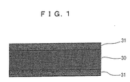
- a solid electrolyte fuel cell includes a solid electrolyte 30 made of a protonic oxide conductor, and a pair of electrodes 31 and 31.
- the solid electrolyte fuel cell of this example is formed of: a solid electrolyte made of a protonic oxide conductor having a composition represented by Ba (Zr 1-x Ce x ) 1-y M y Al z O 3- ⁇ (M: one or more kinds of elements selected from a group of tri-valent rare earth elements and In, 1 ⁇ x >. 0, 0.3 > y > 0, 0.04 > z ⁇ 0, and 1.5 > ⁇ > 0); and electrodes mainly made of platinum and having a catalyst function.
- the solid electrolyte has a thickness of 300 ⁇ m or less and allows the fuel cell to operate, without humidifying, at temperatures from room temperature to less than 350 degrees centigrade.
- a cylindrical sintered body (diameter: 13mm, a thickness: 10mm) of a protonic oxide conductor that is a solid electrolyte was compounded according to a high-temperature solid phase method, then this was cut and polished to a thin plate having a thickness of 300 ⁇ m or less.
- platinum paste available from Tanaka Kikinzoku Kogyo K.K.
- the cell for the fuel cell was structured so that it could be maintained at a constant temperature by being externally heated with a heater.
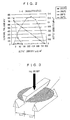
- FIG. 2 an example of power generating properties (I-V characteristics) at various temperatures of a battery cell in which 220 ⁇ m thick BaZr 0.4 Ce 0.4 In 0 . 2 O 3- ⁇ is used as a solid electrolyte is shown.
- Fig. 2 shows relationship between terminal voltage (mV), output current ( ⁇ A/cm 2 ) and output density (mW/cm 2 ) at 200 and 350 degrees centigrade.
- a solid electrolyte fuel cell capable of generating power in the neighborhood of room temperature can be provided. It is clean from Fig. 1 and Table 1 that even at temperatures higher than room temperature, for instance, 300 and 500 degrees centigrade, power can be generated.
- a thickness of the electrolyte is made thinner, cell internal resistance can be made lower, resulting in an improvement in output characteristics of a battery.
- the thinning of a film by machining and polishing largely depends on the mechanical strength of the material.
- a lower limit in thickness is 450 to 500 ⁇ m.
- the solid electrolyte preferably has a film structure of 300 ⁇ m or less.
- a disc-like sample 1 having a diameter of 13 mm was prepared.
- the disc-like sample 1 was supported at both sides thereof 10 mm apart, and on a diameter portion at center thereof, a weight of 1 kg was applied to evaluate the bending strength.
- Electrolyte Material Limit Thickness that can withstand 1 kg Weight ( ⁇ m) BaZr 0.4 Ce 0.4 ln 0.2 O 3- ⁇ 250 BaZr 0.6 Ce 0.2 Gd 0.2 O 3- ⁇ 300 BaZr 0.4 Ce 0.4 Y 0.2 O 3- ⁇ 300 BaZr 0.4 Ce 0.4 Yb 0.2 O 3- ⁇ 250 BaCe 0.8 Gd 0.2 O 3- ⁇ 350 BaCe 0.8 Gd 0.2 Al 0.02 O 3- ⁇ 250 BaZr 0.4 Ce 0.4 In 0.2 Al 0.02 O 3- ⁇ 200 BaZr 0.6 Ce 0.2 Gd 0.2 Al 0.02 O 3- ⁇ 250 BaZr 0.52 Ce 0.24 Gd 0.24 O 3- ⁇ 250 BaZr 0.56 Ce 0.24 Gd 0.2 O 3- ⁇ 200 BaZr 0.3 Ce 0. In 0.2 O 3- ⁇ 250
- the ones that were not insufficient in the mechanical strength were reinforced in the mechanical strength with resin.
- a sintered electrolyte was cut and made thin by polishing.
- the reinforcement was applied with an epoxy resin frame 3 as a supporting structure.
- the epoxy resin frame 3 was formed in such a shape that it had a thickness of 1 mm and an opening of 3 mm ⁇ 3mm in a center portion of a rectangle of 9 mm ⁇ 9 mm.
- a 5 mm ⁇ 5 mm rectangular solid electrolyte film 2 was held at a periphery portion thereof, and a top and bottom surface of the solid electrolyte film 2 were structured so as to face from the opening of the epoxy resin frame 3.
- the solid electrolyte film 2 was held at a substantially central position in a thickness direction of the epoxy resin frame 3.
- a sample 4 that has such epoxy resin frame 3 was subjected to a test similar to the above. That is, support tables were disposed 5 mm apart left and right with a diagonal line of the rectangular epoxy resin frame 3 at a center, and, along the diagonal line of the rectangle, a weight of 1 kg was applied on the epoxy resin frame 3.
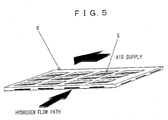
- a top surface of a cell 5 of a solid electrolyte fuel cell faces an air feed path through a rectangular opening, and a bottom surface of the cell 5 of the solid electrolyte fuel cell faces a hydrogen path formed in the epoxy resin frame 6.
- arrow marks show directions of the hydrogen path and air path, respectively.
- the resin was epoxy-based resin; however, other resins, for instance, polypropylene-based, polyethylene-based, polyamide-based, polyimide-based, silicone-based, and Teflon-based resin can also be used.
- Electrode materials other than the platinum paste used in Example 1, such as a paste of fine particle platinum, various kinds of pastes of gold, silver, copper and nickel, a paste of platinum supported on carbon, and a paste of a 1: 1 mixture by weight of fine particulate platinum and BaZr 0.4 Ce 0.4 In 0.2 O 3- ⁇ were subjected to the test.
- FIG. 6 output characteristics (I-V characteristics) of fuel cells at 200 degrees centigrade when various kinds of electrodes were used are shown.
- line L1, line L2, line L3 and line L4, respectively, show output characteristics of the high-temperature printed platinum electrode, particulate platinum electrode, platinum supported on carbon electrode, and mixture electrode of the particulate platinum and the electrolyte.
- the mixture of the protonic oxide conductor (electrolyte material) and the particulate platinum, or the platinum supported on carbon was used, higher cell output could be taken out.
- the electrode of the mixture of the platinum particulate and the electrolyte in addition to obtaining high cell characteristics, has a large effect in reinforcing the strength of the thin plate of the electrolyte.
- the bending strength was actually measured according to the method shown in Example 2, it was found that the mixture electrode was up to two-times stronger.
- the mixing ratio may be 1: 2 or 2: 1; furthermore, the electrolyte material may not be utterly the same one as the electrolyte.
- the particulate platinum in the range of from 20 to 30 nm was used; however, fine particles other than the above may be used.
- the present example relates to a fuel cell that includes a solid electrolyte made of a protonic oxide conductor, an electrode mainly made of platinum and having catalyst performance, and a porous electrode formed of a porous material that carries platinum; wherein a film of the solid electrolyte is formed on the porous electrode, and a method of manufacturing the same.
- the electrolyte of a fuel cell since the thinner the film (when a distance between electrodes is made smaller), the lower the electric resistance of the film, an amount of electricity (current output) that can be extracted can be improved. Accordingly, the electrolyte is necessary to be made thinner and denser. However, when the electrolyte is made thinner, the mechanical strength becomes smaller, resulting in difficulty in configuring a battery.
- a porous electrode supports the mechanical strength.
- the powder mixture was subjected to degreasing followed by sufficient drying.
- the powder was transferred into a ceramic crucible and sintered at 1050 degrees centigrade for 12 hrs, then taken out, and pulverized in benzene that was a nonaqueous solvent by use of a planetary ball mill.
- a planetary ball mill By the pulverization with the planetary ball mill, particles were pulverized to 1 ⁇ m or less in particle size.
- the pulverized powder was thoroughly dewatered by use a vacuum dryer, mixed at a ratio of 1: 1 by volume with platinum powder having a particle diameter of 1 ⁇ m or less in toluene, further mixed with 10 weight percent of polyvinyl alcohol, furthermore mixed with 5 weight percent of dibutyl phthalate as a plasticizer, and thereby a slurry was prepared. Toluene as a solvent was added in half an amount of the powder by weight ratio.
- the slurry was coated, according to a Doctor Blade method, at a thickness of 1 mm on a polyethylene terephthalate sheet, followedby, after degassing and drying, sintering in an electric furnace at 1100 degrees centigrade for 8 hr.
- An obtained sheet was a porous platinum cermet (porous electrode) having porosity of approximately 20 percent and a thickness of 0.7 mm. Furthermore, the bending strength of the sheet, according to the measurement method of Example 2, was enough to withstand a weight of 1 kg.
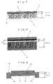
- a cell of a fuel cell shown in a sectional view of Fig. 7 was prepared.
- a platinum electrode 8 was printed and baked.
- a carbon black electrode 10 was coated followed by thermo-compression bonding with the electrolyte film 7, and thereby a cell of a fuel cell was prepared.
- the porous electrode 9 functions as a structural material that reinforces the electrolyte film 7.
- Example 2 To the cell, similarly to Example 1, hydrogen and air were fed to study power-generating properties of the cell. The output was stably extracted, and a maximum output of 0.004 mW/cm 2 at room temperature was obtained. It was confirmed to operate as a fuel cell at room temperature.
- the porous electrode was prepared by sintering after the sheet formation; however, there is no need of forming in the sheet, a bulk body can be used, or in the preparation of the slurry, other materials can be used for the binder and the solvent, and the mixing amounts are not stipulated.
- the slurry may be prepared according to whatever methods, and, the electrolyte film, though prepared from a sintered body in the example, may be prepared from sheet or obtained by use of a gaseous phase method such as vapor deposition and sputtering.
- the present example relates to a solid electrolyte fuel cell in which an electrolyte of a protonic oxide conductor is an integrated body of a dense sintered body and a porous sintered body, and a method of manufacturing the same.
- the manufacturing method is one in which sheets of an electrolyte slurry are sintered; in that case, green sheets in which amounts of organic binders are varied are prepared, and at least two kinds or more of sheets are superposed and co-sintered.
- BaZr 0.6 Ce 0.2 Gd 0.2 Al 0.02 O 3- ⁇ was used for the electrolytematerial.
- Predetermined amounts of barium acetate, zirconium hydroxide, cerium oxide, gadolinium oxide, and aluminum hydroxide were weighed and pulverized and mixed in an alcohol solvent by use of a mortar followed by a ball mill until an average particle diameter of 1 ⁇ m or less was obtained.
- the powder mixture was subjected to degreasing followed by sufficient drying.
- the powder was transferred into a ceramic crucible and sintered at 1300 degrees centigrade for 12 hrs, then taken out and pulverized in benzene that is a nonaqueous solvent by use of a planetary ball mill.
- a planetary ball mill By the pulverization with the planetary ball mill, particles were pulverized to 1 ⁇ m or less in particle size.
- Thepulverizedpowder wasthoroughly dewatered by use a vacuum dryer, and thereby a dry electrolyte powder was obtained.
- a solvent mixture of butyl acetate and butyl cellosolve (4:1 by weight ratio) was added in an amount of a half a weight of the powder, followed by mixing and then pulverizing by use of a ball mill.
- the powder was pulverized with 5 ⁇ zirconia balls and a polyethylene vessel for 24 hrs, after the pulverization, passed through a #32 mesh filter to separate balls as media and the slurry.
- a slurry for use in the dense film was prepared. After a weight of the slurry was measured again, thereto was mixed 6 weight percent of polyvinyl butyral (PVB) as a binder, furthermore added2 weight percent of butylbenzil phthalate (BBP) as a plasticizer, and thereby a slurry was prepared. An amount of a solvent was set at a half a weight of the powder. The slurry was again mixed by use of a ball mill, after the vacuum degassing, coated in sheet on a polyethylene terephthalate sheet according to the Doctor Blade method. A gap of the Doctor Blade was set at 500 ⁇ m in the example and the sheet was run at a speed of substantially 20mm/sec. After the coating, the sheet was dried. A thickness of the obtained sheet was in the range of 130 to 140 ⁇ m.
- PVB polyvinyl butyral
- BBP butylbenzil phthalate
- a slurry for use in the porous film was prepared.
- sheets were prepared.
- an amount of PVB as a binder and that of a plasticizer were set at 12 weight percent and 4 weight percent, respectively.
- sheets were prepared by use of the Doctor Blade, and thicknesses of the obtained sheets were in the range of approximately 100 to 120 ⁇ m.
- a fuel cell that has an integrated structure of a dense sintered body and a porous sintered body was manufactured as follows. First, one green sheet for use in the dense body and four sheets for use in the porous film were cut into two cm square and pressurized at 80 degrees centigrade under a pressure of 4 ⁇ 10 7 Pa to laminate. After the lamination, the laminated body was further cut into a 15 mm square, thrown into an electric furnace, and sandwiched from up and down with alumina plane tables . A weight of a top aluminum plate was approximately 100 g. In this state, the electric furnace was heated to 1600 degrees centigrade, and the laminated body was sintered at this temperature for 10 hrs in air.
- the obtained sheet was an integrated sintered body of the dense film and the porous films having a total thickness of approximately 0.35 mm, and exhibited the bending strength that could withstand a weight of 1 kg according to the measurement method of Example 2. Furthermore, when the air-tightness test was carried out, it was found to have the permeability of 1 ⁇ 10 -3 mL ⁇ mm/atm ⁇ min ⁇ cm 2 or less, that is, sufficient air-tightness.
- a cell for a fuel cell of which sectional view is shown in Fig. 8 was prepared.
- a platinum carbon paste 13 was coated, subjected to hot pressing at 200 degrees centigrade, and thereby a battery was prepared.
- the integrated electrolyte 12 of the porous body 12 1 and dense body 12 2 could function as a structural material.
- Example 2 To the cell, similarly to Example 1, hydrogen and air were fed and the power-generating properties of the cell were investigated. The output was stably extracted, and at room temperature and 300 degrees centigrade, maximum outputs of 0.006 mW/cm 2 and 1 mW/cm 2 , respectively, were obtained. It was confirmed that it could excellently be operated as a fuel cell from room temperature to 300 degrees centigrade.
- the preparation of the slurry is not restricted to the example; that is, the binder and the solvent may be other substances, and neither the mixing amount nor the Doctor Blade gap is stipulated. Furthermore, when an integrated electrolyte of the dense and porous films is prepared, in the present example, one dense film and four porous films were used; however, for instance, three porous films may be laminated on the respective surfaces of one dense film, the number to be laminated and the method to laminate may conform to cell design.
- the sintering temperature and the sintering method may have any patterns .
- the preparation of the electrode is not provided either.
- the present example relates to a fuel cell that includes a solid electrolyte of a protonic oxide conductor, and electrodes that are mainly made of platinum and have catalyst performance, wherein the solid electrolyte is a flat film body, and the flat film body and a supporting structure are integrated in one body, and a method of manufacturing the same.
- a method of sintering from sheets of an electrolyte slurry is adopted in which at least two or more sheets are stacked and co-sintered, and thereby the integrated structure is prepared.
- a slurry is prepared. After a weight of the slurry. was measured again, thereto was mixed 6 weight percent of polyvinyl butyral (PVB) as a binder, furthermore was added 2 weight percent of butylbenzil phthalate (BBP) as a plasticizer, and thereby a slurry was prepared. An amount of a solvent was set at a half a weight of the powder.
- the slurry was again mixed by use of a ball mill, after the vacuum degassing, coated in sheet on a polyethylene terephthalate sheet according to the Doctor Blade method. A gap of the Doctor Blade was set at 500 ⁇ m in the example and the sheet was run at a speed of approximately 20 mm/sec. After the coating, the sheet was dried. A thickness of the obtained sheet was in the range of 130 to 140 ⁇ m.
- a fuel cell in which a flat film body and a supporting structure were integrated in one body was prepared as follows.
- a green sheet was first cut as it is into 2 cm square, then four green sheets were cut in frame so as to be 2 cm square and 1 cm in width. These sheets were stacked with their edges aligned and laminated at 80 degrees centigrade and under a pressure of 4 ⁇ 10 7 Pa.
- This was put into an electric furnace with the laminated body sandwiched from up and down with alumina plates. A weight of the alumina plate at the upper portion was approximately 100 g. Then, the electric furnace was heated to 1600 degrees centigrade, and the sandwiched body was sintered there in air for 10 hrs.
- the obtained integrated sintered body had a thickness of approximately 0.5 mm at the periphery thereof and the flat film body was dense and had a thickness of approximately 100 ⁇ m.
- the bending strength according to the method mentioned in Example 2 was enough to withstand a weight of 1 kg.
- the air tightness test showed it had the permeability of 1 ⁇ 10 -3 mL•mm/atm•min•cm 2 , that is, sufficient air-tightness.
- a cell of a fuel cell shown with a sectional view in Fig. 9 was prepared.
- a platinum paste as electrodes 15 was coated and baked at 850 degrees centigrade, and thereby a battery was prepared.
- the integrated electrolyte 14 of the flat film body 14 1 and the supporting structure 14 2 was found to function also as a structural material.
- Example 2 To the cell, similarly to Example 1, hydrogen and air were fed and the power-generating properties of the cell were investigated. The output was stably extracted, and at room temperature and 300 degrees centigrade, maximum outputs of 0.003 mW/cm 2 and 0.5 mW/cm 2 , respectively, were obtained. It was confirmed that it could be excellently operated as a fuel cell from room temperature to 300 degrees centigrade.
- the preparation of the slurry is not restricted to the example; that is, the binder and the solvent may be other substances, neither the mixing amount nor the Doctor Blade gap is provided. Furthermore, when an integrated electrolyte of the flat film body and the supporting structure is prepared, in the present example, as to the green sheet, one of the plane table sheet and four of the cut-out sheets were used; however, for instance, two of plane table sheets and five cut-out sheets may be laminated, and the method to cut out may conform to cell design.
- the sintering temperature and the sintering method may have any patterns.
- the preparation of the electrode is not provided either.
- the present example shows that a collective cell that is actually assembled with carbon material and stainless steel for a housing and a separator can be stably operated.
- FIG. 10 a configuration of a fuel cell prepared according to the example is shown.
- a solid electrolyte 16 BaZr 0.4 Ce 0.4 In 0.2 Al 0.02 O 3 - ⁇ having a diameter of 13 mm and a thickness of 220 ⁇ m was used, and, in the same drawing, an anode on a top surface side and a cathode on a bottom surface side were formed with platinum material. This was adhered to a ceramic substrate 17 to hold.
- the adhesion was carried out as follows. That is, in recess portions of the substrate 17 that has four openings having a diameter of 9 mm and in which circular recesses having a diameter of 13.5 mm with a center at the center of the opening are formed for accommodating solid electrolytes 16, the solid electrolytes 16 provided with the anode and the cathode were accommodated and periphery portions thereof were adhered to the substrate. The anode and the cathode were formed so as to face from the openings.
- the cell was constituted with stainless steel current collectors embracinga separator 18 superposed fromabove and below.
- the current collector embracing the separator 18 combined with the housing.
- SUS 304 that contains 18 percent of Cr, 8 percent of Ni, 71 percent of Fe and other elements of 3 percent was used. Furthermore, the thermal expansion coefficient thereof was 11 ⁇ 10 -6 /K, and the thermal expansion coefficients of the electrolyte and the ceramic substrate, respectively, were 10.5 ⁇ 10 -6 /K and 11 ⁇ 10 -6 /K that are close to that of the stainless steel.
- a total electrode area of the fuel cell was 2 cm 2 .
- the electrolyte was made of BaZr 0.4 Ce 0.4 ln 0.2 Al 0.02 O 3- ⁇ and the electrode was made of platinum; however, other protonic oxide conductors may be used and the electrode may not be platinum.
- SUS 304 stainless steel was used for the current collector that combines with the separator; however, the stainless steel may be SUS 430 or a metal with iron as main component containing 18 percent or less Cr, or a carbon material or a resin material may be used.
- the current collector is formed of a resin material, wiring for the current collector can be previously disposed.
- the ceramic one was used in the example; however, design and material thereof may be any one.
- the stainless steel is preferably one that is mainly made of iron and contains 20 percent or less of Cr element, and the thermal expansion coefficient thereof is preferably 9 - 15 ⁇ 10 -6 /K.
- a configuration of a three-cell stack fuel cell manufactured according to the example is shown.
- a solid electrolyte 19 a 20 mm square and 280 ⁇ m thick BaZr 0.6 Ce 0.2 Gd 0.2 Al 0.02 O 3- ⁇ plate was used, and for an anode 20 and a cathode on a back surface side, platinum material was used.
- Separators 21 made of a carbon material were disposed above and below the cell to form a collective cell.
- isotropic graphite G347 manufactured by Tokai Carbon Co.,Ltd was used.
- the thermal expansion coefficient and resistance thereof, respectively, were 4.2 ⁇ 10 -6 /K and 11 ⁇ ⁇ m.
- a total electrode area of the fuel cell was 6.75 cm 2 .
- hydrogen and air were flowed at a flow rate of 50 cc/min, and thereby the power-generating test was carried out.
- Reference numerals 21 1 and 21 2 respectively, denote an inlet and an outlet of hydrogen
- reference numerals 21 3 and 21 4 respectively, denote an inlet of air and an outlet of an exhaust gas.
- the collective cell excellently generated power, and results are shown in Fig. 13.
- the power-generating characteristics of the collective cell were the same as a total of that of single cells, that is, it was found to operate as a collective cell.
- the carbon can be more easily machined in comparison with the oxide and is less expensive.
- the carbon material is superior in the durability.
- Fig. 14 a schematic diagram of a housing that accommodates the collective cell of Fig. 11 is shown.
- reference numeral 25 denotes a housing body made of a resin material
- reference numeral 26 denotes a gas feed portion made of metal
- reference numeral 27 denotes a current collector (current collector housing) made of metal.
- a lower limit of the cell power generation was set at 0.001 mW/cm 2 ; with respect to the sheet resistivity at this time (approximately 10000 ⁇ cm 2 ), the electrolyte films were evaluated according to three grades of excellent material o ⁇ , applicable material ⁇ and material difficult to apply ⁇ . Results are shown in Table 3. In Table 3, minimum sheet resistivities at room temperature are shown.
- Electrolyte materials according to the invention were evaluated as excellent materials o ⁇ , or applicable materials ⁇
Landscapes
- Engineering & Computer Science (AREA)
- Chemical & Material Sciences (AREA)
- Manufacturing & Machinery (AREA)
- General Chemical & Material Sciences (AREA)
- Electrochemistry (AREA)
- Chemical Kinetics & Catalysis (AREA)
- Life Sciences & Earth Sciences (AREA)
- Sustainable Development (AREA)
- Sustainable Energy (AREA)
- Materials Engineering (AREA)
- Fuel Cell (AREA)
- Inert Electrodes (AREA)
- Inorganic Compounds Of Heavy Metals (AREA)
- Compounds Of Alkaline-Earth Elements, Aluminum Or Rare-Earth Metals (AREA)
Abstract
Description
| Electrolyte Material | Film Thickness | Maximum Output Density (mW/cm2) | |||
| Thickness (µm) | 350°C | 200°C | 100° | 30°C | |
| BaZr0.4Ce0.4In0.2O3-α | 220 | 0.12 | 0.004 | - | - |
| BaZr0.6Ce0.2Gd0.2O3-α | 300 | 0.1 | 0.003 | - | |
| BaZr0.4Ce0.4Y0.2O3-α | 300 | 0.2 | 0.006 | - | - |
| BaZr0.4Ce0.4Yb0.2O3-α | 250 | 0.4 | 0.01 | 0.001 | - |
| BaCe0.8Gd0.2O3-α | 300 | 0.9 | 0.03 | 0.002 | 0.0005 |
| BaCe0.8Gd0.2Al0.02O3-α | 150 | 1.2 | 0.04 | 0.003 | 0.001 |
| BaZr0.4Ce0.4In0.2Al0.02O3- | 100 | 0.25 | 0.01 | 0.001 | 0.0001 |
| BaZr0.5Ce0.2Gd0.2Al0.02O3- | 150 | 0.2 | 0.006 | 0.0002 | - |
| BaZr0.52Ce0.24Gd0.2< | 150 | 1.0 | 0.03 | 0.001 | 0.0002 |
| BaZr0.56Ce0.24Gd0.2O3-α | 100 | 1.5 | 0.06 | 0.004 | 0.002 |
| BaZr0.3Ce0.5In0.2O3-α | 100 | 1.4 | 0.05 | 0.003 | 0.002 |
| Electrolyte Material | Limit Thickness that can withstand 1 kg Weight (µm) |
| BaZr0.4Ce0.4ln0.2 | 250 |
| BaZr0.6Ce0.2Gd0.2O3-α | 300 |
| BaZr0.4Ce0.4Y0.2O3-α | 300 |
| BaZr0.4Ce0.4Yb0.2O3-α | 250 |
| BaCe0.8Gd0.2O3-α | 350 |
| BaCe0.8Gd0.2Al0.02O3-α | 250 |
| BaZr0.4Ce0.4In0.2Al0.02O3-α | 200 |
| BaZr0.6Ce0.2Gd0.2Al0.02O3-α | 250 |
| BaZr0.52Ce0.24Gd0.24O3-α | 250 |
| BaZr0.56Ce0.24Gd0.2O3-α | 200 |
| BaZr0.3Ce0.In0.2 | 250 |
| Electrolyte Material | Minimum Sheet | Evaluation |
| Resistivity (Ω cm2) < specific resistance × film thickness> | ||
| BaZr0.6Ce0.2Gd0.2O3-α | 1000 | o ○ |
| BaZr0.4Ce0.4Gd0.1In0.1O3-α | 920 | o ○ |
| BaZr0.4Ce0.4Nd0.2O3-α | 2050 | ○ |
| BaCe0.8Sm0.2O3-α | 1220 | ○ |
| BaCe0.8Dy0.2O3-α | 2340 | ○ |
| BaCe0.8Eu0.2Al0.02O3-α | 1655 | ○ |
| BaCe0.8Pr0.2O3-α | 4550 | ○ |
| BaCe0.8Pm0.2O3-α | 3310 | ○ |
| BaCe0.8La0.2O3-α | 8620 | ○ |
| BaCe0.8Tb0.2O3-α | 4680 | ○ |
| BaCe0.8Ho0.2O3-α | 6770 | ○ |
| BaCe0.8Er0.2O3-α | 7930 | ○ |
| BaCe0.8Tm0.2O3-α | 9620 | ○ |
| BaCe0.8Lu0.2O3-α | 8440 | ○ |
| BaCe0.8Sc0.2O3-α | 2660 | ○ |
| BaZr0.4Ce0.4Gd0.1In0.2Al0.02O3-α | 3260 | ○ |
| BaZr0.6Ce0.2Gd0.1Y0.1AL0.02O3-α | 1580 | ○ |
| BaZr0.4Ce0.2Gd0.4O3-α | 12000 | × |
| BaZr0.6Ce0.1In0.3O3-α | 10050 | × |
| BaZr0.3Ce0.5ln0.2Al0.05O3-α | 10100 | × |
| YSZ | > 50000 | × |
| o ○: excellent material, ○: applicable material, and ×: material difficult to apply. |
Claims (68)
- A solid electrolyte fuel cell including:wherein the solid electrolyte is a protonic oxide conductor having a composition represented by Ba (Zr1-xCex)1-yMyAlzO3-α (M: one or more kinds of elements selected from a group of tri-valent rare earth elements and In, 1 > x > 0, 0.3 > y > 0, 0.04 > z > 0, and 1.5 > α > 0).a pair of electrodes; anda solid electrolyte disposed between the electrodes;
- A solid electrolyte fuel cell including:wherein the solid electrolyte is a protonic oxide conductor having a composition represented by BaCe1-yMyAlzO3-α (M: one or more kinds of elements selected from a group of tri-valent rare earth elements and In, 0.3 > y > 0, 0.04 > z > 0, and 1.5 > α > 0) .a pair of electrodes; anda solid electrolyte disposed between the electrodes;
- A solid electrolyte fuel cell including:wherein the solid electrolyte is a protonic oxide conductor having a composition represented by BaZr1-yMyAlzO3-α (M: one or more kinds of elements selected from a group of tri-valent rare earth elements and In, 0.3 > y > 0, 0.04 > z > 0, and 1.5 > α > 0) .a pair of electrodes; anda solid electrolyte disposed between the electrodes;
- A solid electrolyte fuel cell including:wherein the solid electrolyte is a protonic oxide conductor having a composition represented by Ba(Zr1-xCex)1-yMyAlzO3-α (M: one or more kinds of elements selected from a group of tri-valent rare earth elements and In, 1 > x > 0, 0.3 > y > 0, 0.04 > z > 0, and 1.5 > α > 0); anda pair of electrodes; anda solid electrolyte disposed between the electrodes;
a supporting structure that supports the solid electrolyte is made of a resin material. - A solid electrolyte fuel cell including:wherein the solid electrolyte is a protonic oxide conductor having a composition represented by BaCe1-yMyAlzO3-α (M: one or more kinds of elements selected from a group of tri-valent rare earth elements and In, 0.3 > y > 0, 0.04 > z > 0, and 1.5 > α > 0); anda pair of electrodes; anda solid electrolyte disposed between the electrodes;
a supporting structure that supports the solid electrolyte is made of a resin material. - A solid electrolyte fuel cell including:wherein the solid electrolyte is a protonic oxide conductor having a composition represented by BaZr1-yMyAlzO3-α (M: one or more kinds of elements selected from a group of tri-valent rare earth elements and In, 0.3 > y > 0, 0.04 > z > 0, and 1.5 > α > 0); anda pair of electrodes; anda solid electrolyte disposed between the electrodes;
a supporting structure that supports the solid electrolyte is made of a resin material. - A solid electrolyte fuel cell including:wherein the solid electrolyte is a protonic oxide conductor having a composition represented by Ba (Zr1-xCex)1-yMyO3-α (M: one or more kinds of elements selected from a group of tri-valent rare earth elements and In, 1 > x > 0, 0.3 > y > 0, and 1.5 > α > 0); anda pair of electrodes; anda solid electrolyte disposed between the electrodes;
a supporting structure that supports the solid electrolyte is made of a resin material. - A solid electrolyte fuel cell including:wherein the solid electrolyte is a protonic oxide conductor having a composition represented by BaCe1-yMyO3-α (M: one or more kinds of elements selected from a group of tri-valent rare earth elements and In, .0.3 > y > 0, and 1.5 > α > 0); anda pair of electrodes; anda solid electrolyte disposed between the electrodes;
a supporting structure that supports the solid electrolyte is made of a resin material. - A solid electrolyte fuel cell including:wherein the solid electrolyte is a protonic oxide conductor having a composition represented by BaZr1-yMyO3-α (M: one or more kinds of elements selected from a group of tri-valent rare earth elements and In, 0.3 > y > 0, and 1.5 > α > 0); anda pair of electrodes; anda solid electrolyte disposed between the electrodes;
a supporting structure that supports the solid electrolyte is made of a resin material. - A solid electrolyte fuel cell as set forth in claim 4:
wherein the M in a composition of the protonic oxide conductor is one or more kinds of elements selected from a group of In, Gd, Y and Yb. - A solid electrolyte fuel cell as set forth in claim 5:
wherein the M in a composition of the protonic oxide conductor is one or more kinds of elements selected from a group of In, Gd, Y and Yb. - A solid electrolyte fuel cell as set forth in claim 6:
wherein the M in a composition of the protonic oxide conductor is one or more kinds of elements selected from a group of In, Gd, Y and Yb. - A solid electrolyte fuel cell as set forth in claim 7:
wherein the M in a composition of the protonic oxide conductor is one or more kinds of elements selected from a group of In, Gd, Y and Yb. - A solid electrolyte fuel cell as set forth in claim 8:
wherein the M in a composition of the protonic oxide conductor is one or more kinds of elements selected from a group of In, Gd, Y and Yb. - A solid electrolyte fuel cell as set forth in claim 9:
wherein the M in a composition of the protonic oxide conductor is one or more kinds of elements selected from a group of In, Gd, Y and Yb. - A solid electrolyte fuel cell as set forth in claim 4:
wherein the electrode is made of platinum supported on carbon. - A solid electrolyte fuel cell as set forth in claim 5:
wherein the electrode is made of platinum supported on carbon. - A solid electrolyte fuel cell as set forth in claim 6:
wherein the electrode is made of platinum supported on carbon. - A solid electrolyte fuel cell as set forth in claim 7:
wherein the electrode is made of platinum supported on carbon. - A solid electrolyte fuel cell as set forth in claim 8:
wherein the electrode is made of platinum supported on carbon. - A solid electrolyte fuel cell as set forth in claim 9:
wherein the electrode is made of platinum supported on carbon. - A solid electrolyte fuel cell as set forth in claim 4:
wherein the electrode is made of a mixture of particulate platinum and a material having the same components as those of the protonic oxide conductor. - A solid electrolyte fuel cell as set forth in claim 5:
wherein the electrode is made of a mixture of particulate platinum and a material having the same components as those of the protonic oxide conductor. - A solid electrolyte fuel cell as set forth in claim 6:
wherein the electrode is made of a mixture of particulate platinum and a material having the same components as those of the protonic oxide conductor. - A solid electrolyte fuel cell as set forth in claim 7:
wherein the electrode is made of a mixture of particulate platinum and a material having the same components as those of the protonic oxide conductor. - A solid electrolyte fuel cell as set forth in claim 8:
wherein the electrode is made of a mixture of particulate platinum and a material having the same components as those of the protonic oxide conductor. - A solid electrolyte fuel cell as set forth in claim 9:
wherein the electrode is made of a mixture of particulate platinum and a material having the same components as those of the protonic oxide conductor. - A solid electrolyte fuel cell including:wherein the solid electrolyte is a protonic oxide conductor; one of the pair of electrodes is an electrode mainly made of platinum; and the other one is a porous electrode made of a porous body carrying platinum.a pair of electrodes; anda solid electrolyte disposed between the electrodes;
- A solid electrolyte fuel cell including:wherein the electrodes are electrodes mainly made of platinum; and the solid electrolyte is a protonic oxide conductor;a pair of electrodes; anda solid electrolyte disposed between the electrodes;
wherein a film body and a supporting structure that supports the film body are integrated into one body. - A solid electrolyte fuel cell including:wherein the solid electrolyte is a protonic oxide conductor and an integrated body of a dense sintered body and a porous sintered body.a pair of electrodes; anda solid electrolyte disposed between the electrodes;
- A solid electrolyte fuel cell as set forth in claim 28:
wherein the solid electrolyte is a protonic oxide conductor having a composition represented by Ba (Zr1-xCex)1-yMyAlzO3-α (M: one or more kinds of elements selected from a group of tri-valent rare earth elements and In, 1 > x > 0, 0.3 > y > 0, 0.04 > z > 0, and 1.5 > α > 0). - A solid electrolyte fuel cell as set forth in claim 28:
wherein the solid electrolyte is a protonic oxide conductor having a composition represented by BaCe1-yMyAlzO3-α (M: one or more kinds of elements selected from a group of tri-valent rare earth elements and In, 0.3 > y > 0, 0.04 > z > 0, and 1.5 > α > 0) . - A solid electrolyte fuel cell as set forth in claim 28:
wherein the solid electrolyte is aprotonicoxide conductor having a composition represented by BaZr1-yMyAlzO3-α (M: one or more kinds of elements selected from a group of tri-valent rare earth elements and In, 0.3 > y > 0, 0.04 > z > 0, and 1.5 > α > 0) . - A solid electrolyte fuel cell as set forth in claim 28:
wherein the solid electrolyte is a protonic oxide conductor having a composition represented by Ba (Zr1-xCex)1-yMyO3-α (M: one or more kinds of elements selected from a group of tri-valent rare earth elements and In, 1 > x > 0, 0.3 > y > 0, and 1.5 > α > 0). - A solid electrolyte fuel cell as set forth in claim 28:
wherein the solid electrolyte is a protonic oxide conductor having a composition represented by BaCe1-yMyO3-α (M: one or more kinds of elements selected from a group of tri-valent rare earth elements and In, 0.3 > y > 0, and 1.5 > α > 0). - A solid electrolyte fuel cell as set forth in claim 28:
wherein the solid electrolyte is a protonic oxide conductor having a composition represented by BaZr1-yMyO3-α (M: one or more kinds of elements selected from a group of tri-valent rare earth elements and In, 0.3 > y > 0, and 1.5 > α > 0). - A solid electrolyte fuel cell as set forth in claim 29:
wherein the solid electrolyte is a protonic oxide conductor having a composition represented by Ba(Zr1-xCex)1-yMyAlzO3-α (M: one or more kinds of elements selected from a group of tri-valent rare earth elements and In, 1 > x > 0, 0.3 > y > 0, 0.04 > z > 0, and 1.5 > α > 0). - A solid electrolyte fuel cell as set forth in claim 29:
wherein the solid electrolyte is a protonic oxide conductor having a composition represented by BaCe1-yMyAlzO3-α (M: one or more kinds of elements selected from a group of tri-valent rare earth elements and In, 0.3 > y > 0, 0.04 > z > 0, and 1.5 > α > 0). - A solid electrolyte fuel cell as set forth in claim 29:
wherein the solid electrolyte is a protonic oxide conductor having a composition represented by BaZr1-yMyAlzO3-α (M: one or more kinds of elements selected from a group of tri-valent rare earth elements and In, 0.3 > y > 0, 0.04 > z > 0, and 1.5 > α > 0). - A solid electrolyte fuel cell as set forth in claim 29:
wherein the solid electrolyte is a protonic oxide conductor having a composition represented by Ba(Zr1-xCex)1-yMyO3-α (M: one or more kinds of elements selected from a group of tri-valent rare earth elements and In, 1 > x > 0, 0.3 > y > 0, and 1.5 > α > 0). - A solid electrolyte fuel cell as set forth in claim 29:
wherein the solid electrolyte is a protonic oxide conductor having a composition represented by BaCe1-yMyO3-α (M: one or more kinds of elements selected from a group of tri-valent rare earth elements and In, 0.3 > y > 0, and 1.5 > α > 0). - A solid electrolyte fuel cell as set forth in claim 29:
wherein the solid electrolyte is a protonic oxide conductor having a composition represented by BaZr1-yMyO3-α (M: one or more kinds of elements selected from a group of tri-valent rare earth elements and In, 0.3 > y > 0, and 1.5 > α > 0). - A solid electrolyte fuel cell as set forth in claim 30:
wherein the solidelectrolyte is a protonicoxide conductor having a composition represented by Ba(Zr1-xCex) 1-yMyAlzO3-α (M: one or more kinds of elements selected from a group of tri-valent rare earth elements and In, 1 > x > 0, 0.3 > y > 0, 0.04 > z > 0, and 1.5 > α > 0). - A solid electrolyte fuel cell as set forth in claim 30:
wherein the solid electrolyte is a protonic oxide conductor having a composition represented by BaCe1-yMyAlzO3-α (M: one or more kinds of elements selected from a group of tri-valent rare earth elements and In, 0.3 > y > 0, 0.04 > z > 0, and 1.5 > α > 0) . - A solid electrolyte fuel cell as set forth in claim 30:
wherein the solid electrolyte is aprotonicoxide conductor having a composition represented by BaZr1-yMyAlzO3-α (M: one or more kinds of elements selected from a group of tri-valent rare earth elements and In, 0.3 > y > 0, 0.04 > z > 0, and 1.5 > α > 0) . - A solid electrolyte fuel cell as set forth in claim 30:
wherein the solid electrolyte is a protonic oxide conductor having a composition represented by Ba (Zr1-xCex)1-yMyO3-α (M: one or more kinds of elements selected from a group of tri-valent rare earth elements and In, 1 > x > 0, 0.3 > y > 0, and 1.5 > α > 0). - A solid electrolyte fuel cell as set forth in claim 30:
wherein the solid electrolyte is a protonic oxide conductor having a composition represented by BaCe1-yMyO3-α (M: one or more kinds of elements selected from a group of tri-valent rare earth elements and In, 0.3 > y > 0, and 1.5 > α > 0). - A solid electrolyte fuel cell as set forth in claim 30:
wherein the solid electrolyte is aprotonicoxide conductor having a composition represented by BaZr1-yMyO3-α (M: one or more kinds of elements selected from a group of tri-valent rare earth elements and In, 0.3 > y > 0, and 1.5 > α > 0). - A solid electrolyte fuel cell including:wherein the solid electrolyte is a protonic oxide conductor having a composition represented by Ba(Zr1-xCex)1-yMyAlzO3-α (M: one or more kinds of elements selected from a group of tri-valent rare earth elements and In, 1 > x > 0, 0.3 > y > 0, 0.04 > z > 0, and 1.5 > α > 0); anda cell including a pair of electrodes; a solid electrolyte disposed between the electrodes; and separators disposed on both sides of the electrodes; anda housing surrounding the cell together with a current collector;
at least any one of the separator, the current collector and the housing is formed of at least any one of resin, carbon and metal. - A solid electrolyte fuel cell including:wherein the solid electrolyte is a protonic oxide conductor having a composition represented by BaCe1-yMyAlzO3-α (M: one or more kinds of elements selected from a group of tri-valent rare earth elements and In, 0.3 > y > 0, 0.04 > z > 0, and 1.5 > α > 0); anda cell including a pair of electrodes; a solid electrolyte disposed between the electrodes; and separators disposed on both sides of the electrodes; anda housing surrounding the cell together with a current collector;
at least any one of the separator, the current collector and the housing is formed of at least any one of resin, carbon and metal. - A solid electrolyte fuel cell including:wherein the solid electrolyte is a protonic oxide conductor having a composition represented by BaZr1-yMyAlzO3-α (M: one or more kinds of elements selected from a group of tri-valent rare earth elements and In, 0.3 > y > 0, 0.04 > z > 0, and 1.5 > α > 0); anda cell including a pair of electrodes; a solid electrolyte disposed between the electrodes; and separators disposed on both sides of the electrodes; anda housing surrounding the cell together with a current collector;
at least any one of the separator, the current collector and the housing is formed of at least any one of resin, carbon and metal. - A solid electrolyte fuel cell including:wherein the solid electrolyte is a protonic oxide conductor having a composition represented by Ba(Zr1-xCex)1-yMyO3-α (M: one or more kinds of elements selected from a group of tri-valent rare earth elements and In, 1 > x > 0, 0.3 > y > 0, and 1.5 > α> 0); anda cell including a pair of electrodes; a solid electrolyte disposed between the electrodes; and separators disposed on both sides of the electrodes; anda housing surrounding the cell together with a current collector;
at least any one of the separator, the current collector and the housing is formed of at least any one of resin, carbon and metal. - A solid electrolyte fuel cell including:wherein the solid electrolyte is a protonic oxide conductor having a composition represented by BaCe1-yMyO3-α (M: one or more kinds of elements selected from a group of tri-valent rare earth elements and In, 0.3 > y > 0, and 1.5 > α > 0); anda cell including a pair of electrodes; a solid electrolyte disposed between the electrodes; and separators disposed on both sides of the electrodes; anda housing surrounding the cell together with a current collector;
at least any one of the separator, the current collector and the housing is formed of at least any one of resin, carbon and metal. - A solid electrolyte fuel cell including:wherein the solid electrolyte is a protonic oxide conductor having a composition represented by BaZr1-yMyO3-α (M: one or more kinds of elements selected from a group of tri-valent rare earth elements and In, 0.3 > y > 0, and 1.5 > α > 0); anda cell including a pair of electrodes; a solid electrolyte disposed between the electrodes; and separators disposed on both sides of the electrodes; anda housing surrounding the cell together with a current collector;
at least any one of the separator, the current collector and the housing is formed of at least any one of resin, carbon and metal. - A solid electrolyte fuel cell as set forth in claim 49:
wherein the metal is stainless steel that is mainly made of iron and contains 20 percent or less of chromium. - A solid electrolyte fuel cell as set forth in claim 50:
wherein the metal is stainless steel that is mainly made of iron and contains 20 percent or less of chromium. - A solid electrolyte fuel cell as set forth in claim 51:
wherein the metal is stainless steel that is mainly made of iron and contains 20 percent or less of chromium. - A solid electrolyte fuel cell as set forth in claim 52:
wherein the metal is stainless steel that is mainly made of iron and contains 20 percent or less of chromium. - A solid electrolyte fuel cell as set forth in claim 53:
wherein the metal is stainless steel that is mainly made of iron and contains 20 percent or less of chromium. - A solid electrolyte fuel cell as set forth in claim 54:
wherein the metal is stainless steel that is mainly made of iron and contains 20 percent or less of chromium. - A solid electrolyte fuel cell as set forth in claim 49:
wherein the metal is stainless steel whose thermal expansion coefficient is in the range of from 9 × 10⁻⁶ to 15 × 10-6/k. - A solid electrolyte fuel cell as set forth in claim 50:
wherein the metal is stainless steel whose thermal expansion coefficient is in the range of from 9 × 10⁻⁶ to 15 × 10-6/K. - A solid electrolyte fuel cell as set forth in claim 51:
wherein the metal is stainless steel whose thermal expansion coefficient is in the range of from 9 × 10⁻⁶ to 15 × 10-6/K. - A solid electrolyte fuel cell as set forth in claim 52:
wherein the metal is stainless steel whose thermal expansion coefficient is in the range of from 9 × 10⁻⁶ to 15 × 10-6/K. - A solid electrolyte fuel cell as set forth in claim 53:
wherein the metal is stainless steel whose thermal expansion coefficient is in the range of from 9 × 10⁻⁶ to 15 × 10-6/K. - A solid electrolyte fuel cell as set forth in claim 54:
wherein the metal is stainless steel whose thermal expansion coefficient is in the range of from 9 × 10⁻⁶ to 15 × 10-6/K. - A method of manufacturing a solid electrolyte fuel cell that includes a pair of electrodes; and a solid electrolyte disposed between the electrodes; wherein the electrode is mainly made of platinum; the solid electrolyte is a protonic oxide conductor; and a film body and a supporting structure that supports the film body are integrated in one body, including:superposing at least two or more sheets of electrolyte slurry and co-sintering, and thereby forming an integrated body.
- A method of manufacturing a solid electrolyte fuel cell that includes a pair of electrodes; and a solid electrolyte disposed between the electrodes; wherein the solid electrolyte is a protonic oxide conductor and an integrated body of a dense sintered body and a porous sintered body, including:preparing sheets of electrolyte slurry for use in dense sintered body and porous sintered body that are different in amount of an organic binder; andsuperposing at least two or more of the sheets and co-sintering, and thereby forming an integrated body of a dense sintered body and a porous sintered body.
Applications Claiming Priority (2)
| Application Number | Priority Date | Filing Date | Title |
|---|---|---|---|
| JP2002165456 | 2002-06-06 | ||
| JP2002165456 | 2002-06-06 |
Publications (3)
| Publication Number | Publication Date |
|---|---|
| EP1369949A2 true EP1369949A2 (en) | 2003-12-10 |
| EP1369949A3 EP1369949A3 (en) | 2007-05-02 |
| EP1369949B1 EP1369949B1 (en) | 2013-01-30 |
Family
ID=29545818
Family Applications (1)
| Application Number | Title | Priority Date | Filing Date |
|---|---|---|---|
| EP03012535A Expired - Lifetime EP1369949B1 (en) | 2002-06-06 | 2003-06-02 | Solid electrolyte fuel cell and manufacturing method thereof |
Country Status (4)
| Country | Link |
|---|---|
| US (1) | US7141327B2 (en) |
| EP (1) | EP1369949B1 (en) |
| JP (1) | JP5076221B2 (en) |
| CN (6) | CN1292510C (en) |
Cited By (3)
| Publication number | Priority date | Publication date | Assignee | Title |
|---|---|---|---|---|
| WO2007138413A3 (en) * | 2006-05-29 | 2008-02-14 | Toyota Motor Co Ltd | Proton conducting oxidic electrolyte for intermediate temperature fuel cell |
| WO2008043943A1 (en) * | 2006-10-11 | 2008-04-17 | Electricite De France | Electrochemical device comprising a proton-conducting ceramic electrolyte |
| TWI742877B (en) * | 2019-11-07 | 2021-10-11 | 日商日立全球先端科技股份有限公司 | Fuel cell, fuel cell system, and fuel cell manufacturing method |
Families Citing this family (14)
| Publication number | Priority date | Publication date | Assignee | Title |
|---|---|---|---|---|
| JP4625658B2 (en) * | 2004-07-21 | 2011-02-02 | 株式会社東芝 | Fuel cell electrode, membrane electrode composite, and fuel cell |
| US20080022514A1 (en) * | 2004-10-08 | 2008-01-31 | Harlan Anderson | Method of making a solid oxide fuel cell having a porous electrolyte |
| US7625653B2 (en) * | 2005-03-15 | 2009-12-01 | Panasonic Corporation | Ionic conductor |
| US8026014B2 (en) * | 2007-05-16 | 2011-09-27 | The Board Of Trustees Of The Leland Stanford Junior University | Solid oxide fuel cell components tuned by atomic layer deposition |
| CA2717285A1 (en) * | 2010-02-09 | 2011-08-09 | The Governors Of The University Of Alberta | Solid oxide fuel cell reactor |
| FR2969395B1 (en) * | 2010-12-17 | 2013-01-11 | Ass Pour La Rech Et Le Dev De Methodes Et Processus Ind Armines | FUEL CELL WITH MONOLITHIC MEMBRANE ELECTROLYTES ASSEMBLY |
| WO2013123319A1 (en) * | 2012-02-17 | 2013-08-22 | Bloom Energy Corporation | Methods and systems for fuel cell stack sintering and conditioning |
| JP6177680B2 (en) * | 2013-12-16 | 2017-08-09 | 三菱日立パワーシステムズ株式会社 | Solid electrolyte fuel cell |
| US9896771B2 (en) | 2014-02-07 | 2018-02-20 | Panasonic Intellectual Property Management Co., Ltd. | Dehydrogenation device |
| CN103825039A (en) * | 2014-02-27 | 2014-05-28 | 盐城工学院 | Electrolyte material and preparation method for intermediate and low-temperature solid oxide fuel cells |
| US20160003767A1 (en) | 2014-07-01 | 2016-01-07 | Panasonic Intellectual Property Management Co., Ltd. | Proton-conducting oxide |
| CN106602136A (en) * | 2016-12-22 | 2017-04-26 | 中国矿业大学 | Barium zirconate-based electrolyte material system and preparation method thereof |
| CN119965311A (en) * | 2018-03-06 | 2025-05-09 | 住友电气工业株式会社 | Battery structure |
| CN117810502A (en) * | 2023-12-01 | 2024-04-02 | 南京工业大学 | A reversible proton ceramic fuel cell electrolyte material, preparation method and application |
Citations (1)
| Publication number | Priority date | Publication date | Assignee | Title |
|---|---|---|---|---|
| EP1125893A1 (en) | 2000-02-14 | 2001-08-22 | Matsushita Electric Industrial Co., Ltd. | Ion Conductor |
Family Cites Families (15)
| Publication number | Priority date | Publication date | Assignee | Title |
|---|---|---|---|---|
| US3266940A (en) * | 1962-04-20 | 1966-08-16 | Socony Mobil Oil Co Inc | Fuel cell containing solid aluminosilicate electrolyte |
| US4024036A (en) * | 1975-02-03 | 1977-05-17 | Agency Of Industrial Science & Technology | Proton permselective solid-state member and apparatus utilizing said permselective member |
| FR2579025B1 (en) * | 1985-03-15 | 1987-04-10 | Occidental Chem Co | IMPROVED SEPARATION FUEL CELL |
| JP2870126B2 (en) * | 1990-05-29 | 1999-03-10 | 松下電器産業株式会社 | Solid oxide fuel cell |
| JP2882104B2 (en) * | 1991-07-17 | 1999-04-12 | 松下電器産業株式会社 | Proton conductor and method for producing the same |
| JP3927663B2 (en) * | 1997-10-15 | 2007-06-13 | 松下電器産業株式会社 | Mixed ion conductor |
| US6306536B1 (en) * | 1998-03-27 | 2001-10-23 | Ballard Power Systems Inc. | Method of reducing fuel cell performance degradation of an electrode comprising porous components |
| US6589410B1 (en) * | 1998-12-24 | 2003-07-08 | Matsushita Electric Industrial Co., Ltd. | Hydrocarbon sensor |
| CA2298850A1 (en) * | 1999-02-17 | 2000-08-17 | Matsushita Electric Industrial Co., Ltd. | Mixed ionic conductor and device using the same |
| JP4608047B2 (en) | 1999-02-17 | 2011-01-05 | パナソニック株式会社 | Mixed ionic conductor and device using the same |
| KR100361548B1 (en) * | 1999-04-19 | 2002-11-21 | 스미토모 긴조쿠 고교 가부시키가이샤 | Stainless steel product for producing polymer electrode fuel cell |
| EP1249052B1 (en) * | 2000-01-18 | 2009-04-22 | Tel-Aviv University Future Technology Development L.P. | Fuels for non-alkaline fuel cells |
| JP3733030B2 (en) * | 2000-02-14 | 2006-01-11 | 松下電器産業株式会社 | Ionic conductor |
| EP1382077A2 (en) * | 2000-07-31 | 2004-01-21 | Nuvant Systems, Inc. | Hydrogen permeable membrane for use in fuel cells, and partial reformate fuel cell system having reforming catalysts in the anode fuel cell compartment |
| JP2002097021A (en) * | 2000-09-19 | 2002-04-02 | Matsushita Electric Ind Co Ltd | High-temperature conductive oxide, fuel cell electrode, and fuel cell using the electrode |
-
2003
- 2003-06-02 EP EP03012535A patent/EP1369949B1/en not_active Expired - Lifetime
- 2003-06-04 US US10/453,535 patent/US7141327B2/en not_active Expired - Lifetime
- 2003-06-06 CN CNB031412076A patent/CN1292510C/en not_active Expired - Lifetime
- 2003-06-06 CN CNA2006100719956A patent/CN1835269A/en active Pending
- 2003-06-06 CN CNA2006100719937A patent/CN1917264A/en active Pending
- 2003-06-06 CN CNB2006100719941A patent/CN100495792C/en not_active Expired - Lifetime
- 2003-06-06 CN CNA2006100719922A patent/CN1835268A/en active Pending
- 2003-06-06 CN CNA2006100719918A patent/CN1905262A/en active Pending
-
2008
- 2008-12-12 JP JP2008316871A patent/JP5076221B2/en not_active Expired - Lifetime
Patent Citations (1)
| Publication number | Priority date | Publication date | Assignee | Title |
|---|---|---|---|---|
| EP1125893A1 (en) | 2000-02-14 | 2001-08-22 | Matsushita Electric Industrial Co., Ltd. | Ion Conductor |
Cited By (4)
| Publication number | Priority date | Publication date | Assignee | Title |
|---|---|---|---|---|
| WO2007138413A3 (en) * | 2006-05-29 | 2008-02-14 | Toyota Motor Co Ltd | Proton conducting oxidic electrolyte for intermediate temperature fuel cell |
| WO2008043943A1 (en) * | 2006-10-11 | 2008-04-17 | Electricite De France | Electrochemical device comprising a proton-conducting ceramic electrolyte |
| FR2907114A1 (en) * | 2006-10-11 | 2008-04-18 | Electricite De France | ELECTROCHEMICAL DEVICE COMPRISING A CERAMIC ELECTROLYTE CONDUCTING PROTONS |
| TWI742877B (en) * | 2019-11-07 | 2021-10-11 | 日商日立全球先端科技股份有限公司 | Fuel cell, fuel cell system, and fuel cell manufacturing method |
Also Published As
| Publication number | Publication date |
|---|---|
| CN1917264A (en) | 2007-02-21 |
| JP5076221B2 (en) | 2012-11-21 |
| CN1905263A (en) | 2007-01-31 |
| JP2009110965A (en) | 2009-05-21 |
| US7141327B2 (en) | 2006-11-28 |
| CN1467869A (en) | 2004-01-14 |
| CN1905262A (en) | 2007-01-31 |
| CN1835268A (en) | 2006-09-20 |
| CN100495792C (en) | 2009-06-03 |
| CN1835269A (en) | 2006-09-20 |
| US20030228509A1 (en) | 2003-12-11 |
| EP1369949A3 (en) | 2007-05-02 |
| CN1292510C (en) | 2006-12-27 |
| EP1369949B1 (en) | 2013-01-30 |
Similar Documents
| Publication | Publication Date | Title |
|---|---|---|
| JP5076221B2 (en) | Solid oxide fuel cell | |
| EP1105929B1 (en) | Planar solid oxide fuel cell stack with metallic foil interconnect | |
| TWI761479B (en) | Electrochemical element, electrochemical module, electrochemical device, energy system, solid oxide fuel cell and manufacturing method for electrochemical element | |
| US10483561B2 (en) | Flat plate-shaped solid oxide fuel cell and cell module comprising same | |
| JP4695826B2 (en) | Solid oxide fuel cell | |
| US11462759B2 (en) | Composite, and electrochemical reaction cell stack | |
| KR102745793B1 (en) | Substrate with electrode layer for metal support type electrochemical element, electrochemical element, electrochemical module, solid oxide fuel cell, and manufacturing method | |
| HK1063104A (en) | Solid electrolyte fuel cell and manufacturing method thereof | |
| JPH06325787A (en) | Solid oxide fuel cell | |
| KR102918740B1 (en) | Electrochemical element, electrochemical module, solid oxide fuel cell and production method | |
| JP7799736B2 (en) | Solid oxide electrolysis cells and their uses | |
| WO2025105416A1 (en) | Solid oxide electrolyzer cell and use of same | |
| Sayan | Investigation of single-step sintering and performance of planar and wavy single-chamber solid oxide fuel cells | |
| WO2025146792A1 (en) | Solid oxide electrolysis cell and use of same | |
| WO2025089330A1 (en) | Solid oxide electrolysis cell and use of same | |
| WO2025169896A1 (en) | Solid oxide electrolysis cell and use thereof | |
| JP2025169747A (en) | Electrochemical reaction single cell and electrochemical reaction cell stack | |
| KR20180036302A (en) | Flat-type solid oxide fuel cell | |
| JP2024116480A (en) | Electrochemical reaction unit cell | |
| KR20250019458A (en) | Stack for solid oxide fuel cell | |
| JPH0562694A (en) | Solid oxide fuel cell | |
| KR20180033827A (en) | Composition for electrolyte of solid oxide fuel cell, electrolyte manufactured by the same, solid oxide fuel cell comprising the same and method for manufacturing thereof | |
| JP2022028167A (en) | Electrochemical reaction single cell | |
| Barton | Investigation of the anode side ohmic losses in anode supported solid oxide fuel cells | |
| HK1096302A (en) | Pharmaceutical composition of a sodium channel blocker and a selective serotonin uptake inhibitor |
Legal Events
| Date | Code | Title | Description |
|---|---|---|---|
| PUAI | Public reference made under article 153(3) epc to a published international application that has entered the european phase |
Free format text: ORIGINAL CODE: 0009012 |
|
| AK | Designated contracting states |
Kind code of ref document: A2 Designated state(s): AT BE BG CH CY CZ DE DK EE ES FI FR GB GR HU IE IT LI LU MC NL PT RO SE SI SK TR |
|
| AX | Request for extension of the european patent |
Extension state: AL LT LV MK |
|
| REG | Reference to a national code |
Ref country code: HK Ref legal event code: DE Ref document number: 1063104 Country of ref document: HK |
|
| RIC1 | Information provided on ipc code assigned before grant |
Ipc: H01M 4/88 20060101ALI20061130BHEP Ipc: H01M 8/12 20060101AFI20030925BHEP Ipc: H01M 4/92 20060101ALI20061130BHEP Ipc: H01M 4/86 20060101ALI20061130BHEP |
|
| PUAL | Search report despatched |
Free format text: ORIGINAL CODE: 0009013 |
|
| AK | Designated contracting states |
Kind code of ref document: A3 Designated state(s): AT BE BG CH CY CZ DE DK EE ES FI FR GB GR HU IE IT LI LU MC NL PT RO SE SI SK TR |
|
| AX | Request for extension of the european patent |
Extension state: AL LT LV MK |
|
| 17P | Request for examination filed |
Effective date: 20070702 |
|
| 17Q | First examination report despatched |
Effective date: 20071023 |
|
| AKX | Designation fees paid |
Designated state(s): DE |
|
| RAP1 | Party data changed (applicant data changed or rights of an application transferred) |
Owner name: PANASONIC CORPORATION |
|
| REG | Reference to a national code |
Ref country code: HK Ref legal event code: WD Ref document number: 1063104 Country of ref document: HK |
|
| GRAP | Despatch of communication of intention to grant a patent |
Free format text: ORIGINAL CODE: EPIDOSNIGR1 |
|
| GRAS | Grant fee paid |
Free format text: ORIGINAL CODE: EPIDOSNIGR3 |
|
| GRAA | (expected) grant |
Free format text: ORIGINAL CODE: 0009210 |
|
| AK | Designated contracting states |
Kind code of ref document: B1 Designated state(s): DE |
|
| REG | Reference to a national code |
Ref country code: DE Ref legal event code: R096 Ref document number: 60343208 Country of ref document: DE Effective date: 20130328 |
|
| PLBE | No opposition filed within time limit |
Free format text: ORIGINAL CODE: 0009261 |
|
| STAA | Information on the status of an ep patent application or granted ep patent |
Free format text: STATUS: NO OPPOSITION FILED WITHIN TIME LIMIT |
|
| 26N | No opposition filed |
Effective date: 20131031 |
|
| REG | Reference to a national code |
Ref country code: DE Ref legal event code: R097 Ref document number: 60343208 Country of ref document: DE Effective date: 20131031 |
|
| PGFP | Annual fee paid to national office [announced via postgrant information from national office to epo] |
Ref country code: DE Payment date: 20220620 Year of fee payment: 20 |
|
| REG | Reference to a national code |
Ref country code: DE Ref legal event code: R071 Ref document number: 60343208 Country of ref document: DE |