EP1369891A2 - Flat display panel and method of manufacturing same - Google Patents
Flat display panel and method of manufacturing same Download PDFInfo
- Publication number
- EP1369891A2 EP1369891A2 EP03012936A EP03012936A EP1369891A2 EP 1369891 A2 EP1369891 A2 EP 1369891A2 EP 03012936 A EP03012936 A EP 03012936A EP 03012936 A EP03012936 A EP 03012936A EP 1369891 A2 EP1369891 A2 EP 1369891A2
- Authority
- EP
- European Patent Office
- Prior art keywords
- substrate
- flange
- ventilation duct
- sealing member
- ventilation
- Prior art date
- Legal status (The legal status is an assumption and is not a legal conclusion. Google has not performed a legal analysis and makes no representation as to the accuracy of the status listed.)
- Withdrawn
Links
Images


Classifications
-
- H—ELECTRICITY
- H01—ELECTRIC ELEMENTS
- H01J—ELECTRIC DISCHARGE TUBES OR DISCHARGE LAMPS
- H01J7/00—Details not provided for in the preceding groups and common to two or more basic types of discharge tubes or lamps
- H01J7/14—Means for obtaining or maintaining the desired pressure within the vessel
- H01J7/22—Tubulations therefor, e.g. for exhausting; Closures therefor
-
- H—ELECTRICITY
- H01—ELECTRIC ELEMENTS
- H01J—ELECTRIC DISCHARGE TUBES OR DISCHARGE LAMPS
- H01J17/00—Gas-filled discharge tubes with solid cathode
- H01J17/02—Details
- H01J17/18—Seals between parts of vessels; Seals for leading-in conductors; Leading-in conductors
- H01J17/183—Seals between parts of vessel
-
- H—ELECTRICITY
- H01—ELECTRIC ELEMENTS
- H01J—ELECTRIC DISCHARGE TUBES OR DISCHARGE LAMPS
- H01J29/00—Details of cathode-ray tubes or of electron-beam tubes of the types covered by group H01J31/00
- H01J29/86—Vessels; Containers; Vacuum locks
-
- H—ELECTRICITY
- H01—ELECTRIC ELEMENTS
- H01J—ELECTRIC DISCHARGE TUBES OR DISCHARGE LAMPS
- H01J9/00—Apparatus or processes specially adapted for the manufacture, installation, removal, maintenance of electric discharge tubes, discharge lamps, or parts thereof; Recovery of material from discharge tubes or lamps
- H01J9/24—Manufacture or joining of vessels, leading-in conductors or bases
- H01J9/26—Sealing together parts of vessels
- H01J9/261—Sealing together parts of vessels the vessel being for a flat panel display
-
- H—ELECTRICITY
- H01—ELECTRIC ELEMENTS
- H01J—ELECTRIC DISCHARGE TUBES OR DISCHARGE LAMPS
- H01J9/00—Apparatus or processes specially adapted for the manufacture, installation, removal, maintenance of electric discharge tubes, discharge lamps, or parts thereof; Recovery of material from discharge tubes or lamps
- H01J9/38—Exhausting, degassing, filling, or cleaning vessels
- H01J9/385—Exhausting vessels
-
- H—ELECTRICITY
- H01—ELECTRIC ELEMENTS
- H01J—ELECTRIC DISCHARGE TUBES OR DISCHARGE LAMPS
- H01J2217/00—Gas-filled discharge tubes
- H01J2217/38—Cold-cathode tubes
- H01J2217/49—Display panels, e.g. not making use of alternating current
- H01J2217/492—Details
- H01J2217/49264—Vessels
Definitions
- This invention relates to structure of a flat display panel and a method of manufacturing the flat display panel.
- a process for exhausting air from the space between the two substrates is typically required in order to produce a vacuum inside the space defined between the two substrates in which light emission is carried out, and/or to keep the space in the state of being filled with a discharge gas.
- Fig. 1 illustrates a conventional structure for exhausting air from the space between the two substrates of such a flat display panel.
- Fig. 1 shows a front glass substrate 1 constituting the display screen of the flat display panel, and a back glass substrate 2 constituting the back part of the flat display panel.
- the flat display panel has the front glass substrate 1 and the back glass substrate 2 facing each other at a predetermined interval.
- a space S thus defined between the glass substrates 1 and 2 is sealed by a sealing layer 3 formed on the peripheral edge between the front glass substrate 1 and the back glass substrate 2.
- a ventilation hole 2A is formed for establishing communication between the space S and the outside in a position on the inner portion of the back glass substrate 2 close to the sealing layer 3.
- a ventilation duct 4 is placed coaxially with the ventilation hole 2A on the outside surface of the back glass substrate 2.
- a seal between an end of the ventilation duct 4 and the ventilation hole 2A is provided by a pressed frit 5.
- the pressed frit 5 is made of a frit paste (sealing materials) essentially consisting of low-melting glass powders, and formed around the opening of the ventilation hole 2A on the back glass substrate 2.
- the flat display panel with the front glass substrate 1 facing downward is supported from beneath by supporting arms M, and then the ventilation duct 4 is mounted on the back glass substrate 2 from above.
- the exhaustion of air from the space S formed between the front glass substrate 1 and the back glass substrate 2, and the infusion of the discharge gas into the space S in the case of PDPs, are carried out via the ventilation hole 2A from the ventilation duct 4 mounted on the back glass substrate 2 as described above.
- the opening of the ventilation duct 4 is sealed to make the space S airtight.
- the flat display panel is supported with the front glass substrate 1 facing downward and the ventilation duct 4 is mounted on the back glass substrate 2 from above. This is because of prevention of imperfect attaching and sealing. If the ventilation duct 4 is mounted on the back glass substrate 2 from beneath while the flat display panel with the back glass substrate 2 facing downward is supported, in the process of forming the pressed frit 5 between the end of the ventilation duct 4 and the ventilation hole 2A by use of the frit paste, the frit paste may run to other unrelated parts and adhere thereto, and the pressed frit 5 may not be formed in a predetermined shape, leading to the imperfect attaching and sealing.
- the present invention has been made to solve the problem associated with the manufacturing process of the flat display panels in the prior art as described above.
- a flat display panel includes a ventilation hole which is formed in a first substrate of two first and second substrates facing each other at a predetermined interval andprovides communicationbetween the space defined between the first and second substrates and the outside, and the flat display panel is characterized by including a sealing member having a central hole, and a ventilation duct which is connected to the ventilation hole and secured with the sealing member onto an outer face of the first substrate and includes a flange formed at one end of the ventilation duct connected to the first substrate, and in that the sealing member is sandwiched between the flange and the first substrate, and fused to both the flange and the first substrate to secure the ventilation duct to the first substrate.
- a method of manufacturing flat display panels according to the present invention is characterized by including the steps of: horizontally supporting the panel, constituted of two substrates facing each other at a required interval, with one of the substrates, having a ventilation hole formed therein to provide communication between the exterior and a space defined between the two substrates, facing downward; preparing a ventilation duct having a flange formed on one end, and a sealing member having a central hole passing therethrough; placing the sealing member in a position connecting the central hole with the ventilation hole opening on the underside of the substrate to sandwich the sealing member between the flange and the underside of the substrate and to align the ventilation duct approximately coaxially with the ventilation hole; and heating the sealing member sandwiched between the flange of the ventilation duct and the underside of the substrate to fuse the sealing member to the flange of the ventilation duct and the underside of the substrate for securing the ventilation duct to the underside of the substrate.
- Fig. 2 is a sectional side view illustrating a flat display panel under the manufacturing process in an embodiment according to the present invention.
- a ventilation hole 12A is formed in the inner portion of the back glass substrate 12 close to the sealing layer 13 and opposite the non-display area, and establishes communication between the space S1 and the outside.
- a ventilation duct 14 is mounted on the back glass substrate 12 so as to communicate with the ventilation hole 12A.
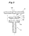
- the ventilation duct 14 has a flange 14A integrally formed at the end of the ventilation duct 14 attached to the back glass substrate 12, and a recess 14B formed on the face of the flange 14A facing the back glass substrate 12.
- a pressed frit 15 providing an airtight seal between the ventilation duct 14 and the back glass substrate 12 is formed of amorphous or crystalline low-melting glass powders (frit) and has a cylindrical part 15A which fits into the recess 14B of the ventilation duct 14, a flange 15B integrally formed on a part of the outer peripheral face of the cylindrical part 15A opposing to the back glass substrate 12, and a ventilation hole 15C formed at the center of the pressed frit 15.
- the front glass substrate 11 and the back glass substrate 12 which are placed opposite to each other at a predetermined interval to define the space S1 sealed by the sealing layer 13, are horizontally supported by supporting arms M1 with the back glass substrate 12 facing downward.
- the ventilation duct 14 and the pressed frit 15 are attached from beneath in an area including the ventilation hole 12A of the back glass substrate 12.
- the pressed frit 15 pre-formed in the shape as described above is attached to the connecting end of the ventilation duct 14 by fitting the cylindrical part 15A into the recess 14B of the ventilation duct 14.
- the ventilation duct 14 with the pressed frit 15 is moved to the underside of the back glass substrate 12, and then adjusted in position such that the ventilation duct 14 and the ventilation hole 15C of the pressed frit 15 are aligned coaxially with the ventilation hole 12A of the back glass substrate 12. Then, the flange 15B of the pressed frit 15 is applied to the underside of the back glass substrate 12.
- the pressed frit 15 is heated until its surface melts, so that the pressed frit 15 is fused to both the back glass substrate 12 and the ventilation duct 14. As a result, by forming a seal between the ventilation duct 14 and the ventilation hole 12A, the ventilation duct 14 is secured to the back glass substrate 12.
- the melted frit paste flowing out from the surface of the pressed frit 15 as a result of the heating is received by the flange 14A of the ventilation duct 14, so that the frit paste does not run to an unrelated area and the pressed frit 15 is not largely deformed by a spill of the frit paste, leading to prevention of impairment of the sealing capability between the ventilation hole 12A and the ventilation duct 14.
- the ventilation duct 14 is attached to the back glass substrate 12 as described above, the air inside the space S1 between the front glass substrate 11 and the back glass substrate 12 is exhausted from the space s1 via the ventilation hole 12A of the back glass substrate 12, the ventilation hole 15C of the pressed frit 15, and then the ventilation duct 14. Then, a discharge gas is infused into the space S1 in inverse order if the flat display panel is a plasma display panel.
- the recess 14B is formed in the flange 14A of the ventilation duct 14, and the cylindrical part 15A of the pressed frit 15 is fitted into the recess 14B. After that, the pressed frit 15 joined to the ventilation duct 14 is hermetically sealed to the back glass substrate 12. For this reason, the running of the frit paste which melts when the pressed frit 15 is heated is definitely prevented.
- the flange of the ventilation duct can provide the required effect of preventing the running of the frit paste when the pressed frit 15 is heated.
- the pressed frit 15 and the ventilation duct 14 may be individually placed sequentially in the predetermined position on the underside face of the back glass substrate 12.
- the pressed frit 15 pre-formed in the predetermined shape desirably is fitted into the flange 14A of the ventilation duct 14, and then the resulting ventilation duct 14 combined with the pressed frit 15 is placed in the predetermined position on the underside face of the back glass substrate 12.
- a flat display panel includes a ventilation hole which is formed in a first substrate of two first and second substrates facing each other at a predetermined interval and provides communication between the outside and the space defined between the first and second substrates.
- the flat display panel has a feature of including a sealing member having a central hole, and a ventilation duct which is connected to the ventilation hole and secured with the sealing member onto an outer face of the first substrate and includes a flange formed at one end of the ventilation duct connected to the first substrate, the sealing member being sandwiched between the flange and the first substrate and fused to both the flange and the first substrate for securing of the ventilation duct to the first substrate.
- the panel in the manufacturing process of the flat display panel, the panel is supported such that one of the two substrates which has the ventilation hole formed therein for exhausting the air from the space between the two substrates points downward. Then the ventilation duct is hermetically sealed from beneath by the sealing member to the substrate which has the ventilation hole formed therein. In this situation, the flange formed on the ventilation duct prevents the sealing member melted by the heating from running downward.
- the panel is supported such that the substrate having the ventilation hole points upward, in order for the ventilation duct to be attached to the substrate from above.
- the present invention allows the attachment of the ventilation duct from beneath while the panel is supported with the substrate, having the ventilation hole, facing downward.
- the formation of the ventilation hole in a back substrate of two substrates constituting of the flat display panel, the back substrate constituting the rear part of the panel, makes it possible to attach the ventilation duct while the panel with the back substrate facing downward is supported. This eliminates the conventional problem of producing scratches or stains on the front substrate as a result of supporting the panel such that the front substrate serving as the display screen for images points downward.
- a method of manufacturing flat display panels according to the present invention has a feature of including the steps of: horizontally supporting the panel, including two substrates opposite each other at a required interval, with one of the substrates facing downward, the downward-facing substrate having a ventilation hole which is formed therein to provide communication between the exterior and the space defined between the two substrates; preparing a ventilation duct having a flange formed at one end, and a sealing member having a central hole; placing the sealingmember in a position connecting the central hole to the ventilation hole opening on the underside of the substrate, to sandwich the sealing member between the flange and the underside of the substrate, and to align the ventilation duct approximately coaxially with the ventilation hole; and heating the sealing member sandwiched between the flange of the ventilation duct and the underside of the substrate to fuse the flange of the ventilation duct to the underside of the substrate for securing the ventilation duct to the underside of the substrate.
- the panel With the method of manufacturing the flat display panels, the panel is supported such that one of the two substrates having the ventilation hole formed therein points downward. Then the ventilation duct is hermetically sealed from beneath by the sealing member to the substrate having the ventilation hole formed therein. At this point, the flange formed on the ventilation duct prevents the sealing member melted by the heating from running downward. Due to this prevention, there is an elimination of the possibility that the melting sealing member will run downward to adhere other unrelated parts, and that the sealing member will be significantly deformed so as to impair the sealing capability between the substrate and the ventilation duct.
- the panel is supported such that the substrate having the ventilation hole points upward, in order for the ventilation duct to be attached to the substrate from above.
- the present invention allows the attachment of the ventilation duct to the substrate from beneath.
- the formation of the ventilation hole in a back substrate of two substrates constituting of the flat display panel, forming the rear part of the panel, makes it possible to attach the ventilation duct while the panel with the back substrate facing downward is supported. This eliminates the conventional problem of producing scratches or stains on the front substrate as a result of supporting the panel such that the front substrate serving as the display screen for images points downward.
Landscapes
- Engineering & Computer Science (AREA)
- Manufacturing & Machinery (AREA)
- Manufacture Of Electron Tubes, Discharge Lamp Vessels, Lead-In Wires, And The Like (AREA)
- Gas-Filled Discharge Tubes (AREA)
- Vessels, Lead-In Wires, Accessory Apparatuses For Cathode-Ray Tubes (AREA)
- Cathode-Ray Tubes And Fluorescent Screens For Display (AREA)
Abstract
Description
Claims (5)
- A flat display panel (10) including a ventilation hole (12A) formed in one (12) of two substrates (11, 12), facing each other at a predetermined interval, and providing communication between the outside and a space (S1) defined between the two substrates (11, 12), and a ventilation duct (14) connected to the ventilation hole (12A) and secured with a sealing member (15) onto an outer face of the substrate (12), characterized in that a flange (14A) is formed at one end of the ventilation duct (14) connected to the substrate (12), and a sealing member (15) having a central hole (15C) is sandwiched between the flange (14A) and the substrate (12), and fused to both the flange (14A) and the substrate (12) to secure the ventilation duct (14) to the substrate (12).
- A flat display panel according to claim 1, wherein a recess (14B) is formed in a face of the flange (14A) of the ventilation duct (14) opposing to the substrate (12), and the sealing member (15) is fitted into the recess (14B) in the flange (14A) of the ventilation duct (14) and fused to both the flange (14A) and the substrate (12).
- A flat display panel according to claim 2, wherein the sealing member (15) is formed in a shape having a cylindrical part (15A) fitted into the recess (14B) of the flange (14A), and a flange (15B) formed at one end of the cylindrical part (15A) close to the substrate (12).
- A method of manufacturing flat display panels, characterized by including the steps of:horizontally supporting the panel (10), constituted of two substrates (11, 12) facing each other at a required interval, with one (12) of the substrates (11, 12), having a ventilation hole (12A) formed therein to provide communication between the exterior and a space (S1) defined between the two substrates (11, 12), facing downward;preparing a ventilation duct (14) having a flange (14A) formed at one end, and a sealing member (15) having a central hole (15C);placing the sealing member (15) in a position connecting the central hole (15C) to the ventilation hole (12A) opening on the underside of the substrate (12) to sandwich the sealing member (15) between the flange (14A) and the underside of the substrate (12) and to align the ventilation duct (14) approximately coaxially with the ventilation hole (12A); andheating the sealing member (15) sandwiched between the flange (14A) of the ventilation duct (14) and the underside of the substrate (12) to fuse the sealing member (15) to the flange (14A) of the ventilation duct (14) to the underside of the substrate (12) for securing the ventilation duct (14) to the underside of the substrate (12).
- A method of manufacturing flat display panels according to claim 4, wherein a recess (14B) is formed in a face of the flange (14A) of the ventilation duct (14) opposite to the substrate (12), and the sealing member (15) is fitted into the recess (14B) formed in the flange (14A) and then comes in contact with the underside face of the substrate (12).
Applications Claiming Priority (2)
| Application Number | Priority Date | Filing Date | Title |
|---|---|---|---|
| JP2002167073 | 2002-06-07 | ||
| JP2002167073A JP2004014332A (en) | 2002-06-07 | 2002-06-07 | Flat display panel and its manufacturing method |
Publications (2)
| Publication Number | Publication Date |
|---|---|
| EP1369891A2 true EP1369891A2 (en) | 2003-12-10 |
| EP1369891A3 EP1369891A3 (en) | 2006-05-03 |
Family
ID=29545881
Family Applications (1)
| Application Number | Title | Priority Date | Filing Date |
|---|---|---|---|
| EP03012936A Withdrawn EP1369891A3 (en) | 2002-06-07 | 2003-06-06 | Flat display panel and method of manufacturing same |
Country Status (3)
| Country | Link |
|---|---|
| US (1) | US6873389B2 (en) |
| EP (1) | EP1369891A3 (en) |
| JP (1) | JP2004014332A (en) |
Families Citing this family (22)
| Publication number | Priority date | Publication date | Assignee | Title |
|---|---|---|---|---|
| JP2004055480A (en) * | 2002-07-24 | 2004-02-19 | Pioneer Electronic Corp | Flat display panel |
| CN1701407A (en) * | 2003-05-19 | 2005-11-23 | 松下电器产业株式会社 | plasma display panel |
| KR101038188B1 (en) * | 2004-11-01 | 2011-06-01 | 주식회사 오리온 | Flat panel with exhaust holes formed in display area |
| US20070096631A1 (en) * | 2005-11-01 | 2007-05-03 | Un-Cheol Sung | Flat panel display and fabricating method thereof |
| KR100671197B1 (en) * | 2005-11-01 | 2007-01-19 | 삼성전자주식회사 | Flat panel display device and manufacturing method thereof |
| KR20080065660A (en) * | 2005-11-11 | 2008-07-14 | 마쯔시다덴기산교 가부시키가이샤 | Display device, vent pipe with glass ring, phosphate glass ring and manufacturing method thereof |
| US8038495B2 (en) * | 2006-01-20 | 2011-10-18 | Samsung Mobile Display Co., Ltd. | Organic light-emitting display device and manufacturing method of the same |
| KR100673765B1 (en) | 2006-01-20 | 2007-01-24 | 삼성에스디아이 주식회사 | Organic light emitting display device and manufacturing method |
| KR100635514B1 (en) | 2006-01-23 | 2006-10-18 | 삼성에스디아이 주식회사 | Organic light emitting display device and manufacturing method |
| KR100688795B1 (en) * | 2006-01-25 | 2007-03-02 | 삼성에스디아이 주식회사 | Organic light emitting display device and manufacturing method |
| US8164257B2 (en) | 2006-01-25 | 2012-04-24 | Samsung Mobile Display Co., Ltd. | Organic light emitting display and method of fabricating the same |
| KR100685853B1 (en) * | 2006-01-25 | 2007-02-22 | 삼성에스디아이 주식회사 | Organic light emitting display device and manufacturing method |
| JP4633674B2 (en) | 2006-01-26 | 2011-02-16 | 三星モバイルディスプレイ株式會社 | Organic electroluminescent display device and manufacturing method thereof |
| KR100671647B1 (en) | 2006-01-26 | 2007-01-19 | 삼성에스디아이 주식회사 | Organic light emitting display device |
| JP2007227131A (en) * | 2006-02-23 | 2007-09-06 | Pioneer Electronic Corp | Flat display panel |
| JP4440225B2 (en) * | 2006-02-28 | 2010-03-24 | パナソニック株式会社 | Method for manufacturing plasma display panel |
| JP4513769B2 (en) * | 2006-02-28 | 2010-07-28 | パナソニック株式会社 | Plasma display panel |
| US8067660B2 (en) * | 2007-06-08 | 2011-11-29 | Honeywell International Inc. | Method and system for restraining a chemical discharge |
| JP2010170871A (en) * | 2009-01-23 | 2010-08-05 | Canon Inc | Airtight container and method for manufacturing image display device |
| JP2010170872A (en) * | 2009-01-23 | 2010-08-05 | Canon Inc | Airtight container and method for manufacturing image display device |
| JP2010170873A (en) * | 2009-01-23 | 2010-08-05 | Canon Inc | Airtight container and method for manufacturing image display device |
| KR101058170B1 (en) | 2011-01-31 | 2011-08-22 | (주)알가 | Vacuum glass panel and its sealing method |
Family Cites Families (8)
| Publication number | Priority date | Publication date | Assignee | Title |
|---|---|---|---|---|
| GB9123460D0 (en) * | 1991-11-05 | 1991-12-18 | Smiths Industries Plc | Radiation-emitting panels and their manufacture |
| US5797780A (en) * | 1996-02-23 | 1998-08-25 | Industrial Technology Research Institute | Hybrid tubeless sealing process for flat panel displays |
| TW358195B (en) * | 1997-01-16 | 1999-05-11 | Sony Co Ltd | Manufacturing method of image display |
| JPH1154052A (en) * | 1997-07-31 | 1999-02-26 | Kyocera Corp | Plasma display device |
| KR100273139B1 (en) * | 1997-11-25 | 2000-12-01 | 정선종 | A packing method of FED |
| KR100255129B1 (en) * | 1997-12-26 | 2000-05-01 | 박호군 | Vacuum packaging apparatus and method for field emission display using the glass-to-glass bonding |
| US6459198B1 (en) * | 2000-05-17 | 2002-10-01 | Motorola, Inc. | Seal and method of sealing devices such as displays |
| EP1174900A1 (en) * | 2000-07-17 | 2002-01-23 | Thomson Plasma S.A.S. | Pumping tube for flat display panel |
-
2002
- 2002-06-07 JP JP2002167073A patent/JP2004014332A/en not_active Abandoned
-
2003
- 2003-06-05 US US10/454,508 patent/US6873389B2/en not_active Expired - Fee Related
- 2003-06-06 EP EP03012936A patent/EP1369891A3/en not_active Withdrawn
Also Published As
| Publication number | Publication date |
|---|---|
| US20030227252A1 (en) | 2003-12-11 |
| US6873389B2 (en) | 2005-03-29 |
| JP2004014332A (en) | 2004-01-15 |
| EP1369891A3 (en) | 2006-05-03 |
Similar Documents
| Publication | Publication Date | Title |
|---|---|---|
| US6873389B2 (en) | Flat display panels and having a ventilation duct secured to a back substrate via a sealing member, and methods of manufacturing the same | |
| JP2002083535A (en) | Sealed container, method of manufacturing the same, and display device | |
| JP4540224B2 (en) | Tablet integrated glass tube | |
| JP2000149791A (en) | Sealing container, sealing method, sealing device, and image forming apparatus | |
| US20060154008A1 (en) | Glass tube, method of manufacturing the glass tube, and method of adhering the glass tube | |
| US6591635B1 (en) | Method of bonding tubulation tubing of display panel | |
| JP3422175B2 (en) | Method of manufacturing gas discharge panel | |
| KR100244895B1 (en) | Method of manufacturing field emission device having subsidiary space | |
| JP2003506298A (en) | Method and apparatus for evacuating a glass panel | |
| US20060150679A1 (en) | Bonding method for vent pipe of display panel | |
| JP2002134018A (en) | Method of manufacturing gas discharge panel | |
| JPS62259329A (en) | Fluorescent character display tube | |
| JP2000195426A (en) | Sealing method, sealed container, image display device, and vacuum exhaust device | |
| CN100499010C (en) | Bonding method for vent pipe of display panel | |
| KR100503592B1 (en) | Sealing adhesion apparatus, sealing adhesion jig, and sealing adhesion method of flat type cathode-ray tube | |
| JPS63207032A (en) | Manufacture of fluorescent character display tube | |
| JP2000106108A (en) | Cathode-ray tube | |
| JP3470437B2 (en) | Flat cathode ray tube | |
| JPH0817343A (en) | Manufacture of cover glass for fluorescent character display tube | |
| JP2005019186A (en) | Plasma display panel, plasma display device, and evacuation glass tube for plasma display panel | |
| US6062932A (en) | Method of forming thin-type display device having a window frame | |
| JPH03263733A (en) | Manufacture of cathode-ray tube | |
| EP1174900A1 (en) | Pumping tube for flat display panel | |
| JP2000200569A (en) | Arc tape and cathode ray tube using the arc tape | |
| JP2003303554A (en) | Plasma display panel and its manufacturing method |
Legal Events
| Date | Code | Title | Description |
|---|---|---|---|
| PUAI | Public reference made under article 153(3) epc to a published international application that has entered the european phase |
Free format text: ORIGINAL CODE: 0009012 |
|
| AK | Designated contracting states |
Kind code of ref document: A2 Designated state(s): AT BE BG CH CY CZ DE DK EE ES FI FR GB GR HU IE IT LI LU MC NL PT RO SE SI SK TR |
|
| AX | Request for extension of the european patent |
Extension state: AL LT LV MK |
|
| PUAL | Search report despatched |
Free format text: ORIGINAL CODE: 0009013 |
|
| AK | Designated contracting states |
Kind code of ref document: A3 Designated state(s): AT BE BG CH CY CZ DE DK EE ES FI FR GB GR HU IE IT LI LU MC NL PT RO SE SI SK TR |
|
| AX | Request for extension of the european patent |
Extension state: AL LT LV MK |
|
| 17P | Request for examination filed |
Effective date: 20060426 |
|
| AKX | Designation fees paid |
Designated state(s): DE FR GB |
|
| STAA | Information on the status of an ep patent application or granted ep patent |
Free format text: STATUS: THE APPLICATION HAS BEEN WITHDRAWN |
|
| 18W | Application withdrawn |
Effective date: 20071001 |