EP1369644A1 - Bande laminée d'un injecteur de carburant - Google Patents
Bande laminée d'un injecteur de carburant Download PDFInfo
- Publication number
- EP1369644A1 EP1369644A1 EP03253522A EP03253522A EP1369644A1 EP 1369644 A1 EP1369644 A1 EP 1369644A1 EP 03253522 A EP03253522 A EP 03253522A EP 03253522 A EP03253522 A EP 03253522A EP 1369644 A1 EP1369644 A1 EP 1369644A1
- Authority
- EP
- European Patent Office
- Prior art keywords
- fuel
- conduit
- annular
- nozzle
- extending
- Prior art date
- Legal status (The legal status is an assumption and is not a legal conclusion. Google has not performed a legal analysis and makes no representation as to the accuracy of the status listed.)
- Granted
Links
Images


Classifications
-
- F—MECHANICAL ENGINEERING; LIGHTING; HEATING; WEAPONS; BLASTING
- F23—COMBUSTION APPARATUS; COMBUSTION PROCESSES
- F23R—GENERATING COMBUSTION PRODUCTS OF HIGH PRESSURE OR HIGH VELOCITY, e.g. GAS-TURBINE COMBUSTION CHAMBERS
- F23R3/00—Continuous combustion chambers using liquid or gaseous fuel
- F23R3/28—Continuous combustion chambers using liquid or gaseous fuel characterised by the fuel supply
-
- F—MECHANICAL ENGINEERING; LIGHTING; HEATING; WEAPONS; BLASTING
- F23—COMBUSTION APPARATUS; COMBUSTION PROCESSES
- F23D—BURNERS
- F23D11/00—Burners using a direct spraying action of liquid droplets or vaporised liquid into the combustion space
- F23D11/36—Details, e.g. burner cooling means, noise reduction means
-
- F—MECHANICAL ENGINEERING; LIGHTING; HEATING; WEAPONS; BLASTING
- F23—COMBUSTION APPARATUS; COMBUSTION PROCESSES
- F23R—GENERATING COMBUSTION PRODUCTS OF HIGH PRESSURE OR HIGH VELOCITY, e.g. GAS-TURBINE COMBUSTION CHAMBERS
- F23R3/00—Continuous combustion chambers using liquid or gaseous fuel
- F23R3/28—Continuous combustion chambers using liquid or gaseous fuel characterised by the fuel supply
- F23R3/34—Feeding into different combustion zones
- F23R3/343—Pilot flames, i.e. fuel nozzles or injectors using only a very small proportion of the total fuel to insure continuous combustion
-
- F—MECHANICAL ENGINEERING; LIGHTING; HEATING; WEAPONS; BLASTING
- F23—COMBUSTION APPARATUS; COMBUSTION PROCESSES
- F23D—BURNERS
- F23D2900/00—Special features of, or arrangements for burners using fluid fuels or solid fuels suspended in a carrier gas
- F23D2900/00003—Fuel or fuel-air mixtures flow distribution devices upstream of the outlet
Definitions
- the present invention relates generally to gas turbine engine combustor fuel injectors and, more particularly, to fuel injector conduits having laminated fuel strips.
- Fuel injectors such as in gas turbine engines, direct pressurized fuel from a manifold to one or more combustion chambers. Fuel injectors also prepare the fuel for mixing with air prior to combustion. Each injector typically has an inlet fitting connected to the manifold, a tubular extension or stem connected at one end to the fitting, and one or more spray nozzles connected to the other end of the stem for directing the fuel into the combustion chamber.
- a fuel conduit or passage e.g., a tube, pipe, or cylindrical passage
- Appropriate valves and/or flow dividers can be provided to direct and control the flow of fuel through the nozzle.
- the fuel injectors are often placed in an evenly-spaced annular arrangement to dispense (spray) fuel in a uniform manner into the combustor chamber.
- An air cavity within the stem provides thermal insulation for the fuel conduit.
- a fuel conduit is needed that can be attached to a valve housing and to the nozzle.
- the fuel conduit should be tolerant of low cycle fatigue (LCF) stresses caused by stretching of the conduit which houses the conduit and which undergoes thermal growth more than the cold conduit.
- the attachment of the conduit to the valve housing should be a reliable joint which does not leak during engine operation. Fuel leaking into the hot air cavity can cause detonations and catastrophic over pressures.
- a fuel injector typically includes one or more heat shields surrounding the portion of the stem and nozzle exposed to high temperature compressor discharge air.
- the heat shields are used for thermal insulation from the hot compressor discharge air during operation. This prevents the fuel from breaking down into solid deposits (i.e., "coking") which occurs when the wetted walls in a fuel passage exceed a maximum temperature (approximately 400 ⁇ F (200 ⁇ C) for typical jet fuel).
- the coke in the fuel nozzle can build up and restrict fuel flow through the fuel nozzle rendering the nozzle inefficient or unusable.
- One such heat shield assembly is shown in U.S. Patent No. 5,598,696 and includes a pair of U-shaped heat shield members secured together to form an enclosure for the stem portion of the fuel injector.
- At least one flexible clip member secures the heat shield members to the injector at about the midpoint of the injector stem.
- the upper end of the heat shield is sized to tightly receive an enlarged neck of the injector to prevent the compressor discharge air from flowing between the heat shield members and the stem.
- the clip member thermally isolates the heat shield members from the injector stem. The flexibility of the clip member permits thermal expansion between the heat shield members and the stem during thermal cycling, while minimizing the mechanical stresses at the attachment points.
- U.S. Patent No. 6,076,356 disclosing a fuel tube completely enclosed in the injector stem such that a stagnant air gap is provided around the tube.
- the fuel tube is fixedly attached at its inlet end and its outlet end to the inlet fitting nozzle, respectively, and includes a coiled or convoluted portion which absorbs the mechanical stresses generated by differences in thermal expansion of the internal nozzle component parts and the external nozzle component parts during combustion and shut-down.
- Many fuel tubes also require secondary seals (such as elastomeric seals) and/or sliding surfaces to properly seal the heat shield to the fuel tube during the extreme operating conditions occurring during thermal cycling.
- heat shield assemblies as described above require a number of components, and additional manufacturing and assembly steps, which can increase the overall cost of the injector, both in terms of original purchase as well as a continuing maintenance.
- the heat shield assemblies can take up valuable space in and around the combustion chamber, block air flow to the combustor, and add weight to the engine. This can all be undesirable with current industry demands requiring reduced cost, smaller injector size (“envelope”) and reduced weight for more efficient operation.
- More conventional nozzles employ primary and secondary nozzles in which only the primary nozzles are used during start-up. Both nozzles are used during higher power operation. The flow to the secondary nozzles is reduced or stopped during start-up and lower power operation.
- Fuel injectors having pilot and main nozzles have been developed for staged combustion. Primary and secondary nozzles discharge at approximately the same axial location in the combustor. Fuel injectors having main and pilot nozzles have been developed for more efficient and cleaner-burning, as the fuel flow can be more accurately controlled and the fuel spray more accurately directed for the particular combustor requirement. Fuel injectors having main and pilot nozzles use multiple fuel circuits discharging into different axial and radial locations in the combustion air flow field to provide good air and fuel mixing at high power.
- the circuits and nozzles which are turned off at low power are referred to as main circuits and main nozzles.
- the circuits and nozzles which are left let on to keep the combustion flame from extinguishing are referred to as pilot circuits and pilot nozzles.
- the pilot and main nozzles can be contained within the same nozzle stem assembly or can be supported in separate nozzle assemblies. Dual nozzle fuel injectors can also be constructed to allow further control of the fuel for dual combustors, providing even greater fuel efficiency and reduction of harmful emissions.
- a typical technique for routing fuel through the stem portion of the fuel injector is to provide a fuel conduit having concentric passages within the stem, with the fuel being routed separately through different passages. The fuel is then directed through passages and/or annular channels in the nozzle portion of the injector to the spray orifice(s).
- U.S. Patent No. 5,413,178 discloses concentric passages where the pilot fuel stream is routed down and back along the main nozzle for cooling purposes. This can also require a number of components and additional manufacturing and assembly steps, which can all be contrary to desirable cost and weight reduction and small injector envelope.
- U.S. Patent No. 6,321,541 addresses these concerns and drawbacks with a fuel injector that includes an inlet fitting, a stem connected at one end to the inlet fitting, and one or more nozzle assemblies connected to the other end of the stem and supported at or within the combustion chamber of the engine.
- a fuel conduit in the form of a single elongated laminated feed strip extends through the stem to the nozzle assemblies to supply fuel from the inlet fitting to the nozzle(s) in the nozzle assemblies.
- An upstream end of the feed strip is directly attached (such as by brazing or welding) to the inlet fitting without additional sealing components (such as elastomeric seals).
- a downstream end of the feed strip is connected in a unitary (one piece) manner to the nozzle.
- the single feed strip has convolutions along its length to provide increased relative displacement flexibility along the axis of the stem and reduce stresses caused by differential thermal expansion due to the extreme temperatures the nozzle is exposed to. This reduces or eliminates a need for additional heat shielding of the stem portion of the injector.
- the laminate feed strip and nozzle are formed from a plurality of plates.
- Each plate includes an elongated, feed strip portion and a unitary head (nozzle) portion, substantially perpendicular to the feed strip portion.
- Fuel passages and openings in the plates are formed by selectively etching the surfaces of the plates.
- the plates are then arranged in surface-to-surface contact with each other and fixed together such as by brazing or diffusion bonding, to form an integral structure.
- Selectively etching the plates allows multiple fuel circuits, single or multiple nozzle assemblies and cooling circuits to be easily provided in the injector.
- the etching process also allows multiple fuel paths and cooling circuits to be created in a relatively small cross-section, thereby, reducing the size of the injector.
- the feed strip portion of the plate assembly is mechanically formed such as by bending to provide the convoluted form.
- the plates all have a T-shape in plan view.
- the head portions of the plate assembly can be mechanically formed into a cylinder having an annular cross-section, or other appropriate shape.
- the ends of the head can be spaced apart from one another or can be brought together and joined, such as by brazing or welding.
- Spray orifices are provided on the radially outer surface, radially inner surface and/or ends of the cylindrical nozzle to direct fuel radially outward, radially inward and/or axially from the nozzle.
- a fuel injector conduit in one embodiment, includes a single feed strip having a single bonded together pair of lengthwise extending plates.
- Each of the plates has a single row of widthwise spaced apart and lengthwise extending parallel grooves. The plates are bonded together such that opposing grooves in each of the plates are aligned forming internal fuel flow passages through the length of the strip from an inlet end to an outlet end.
- the feed strip includes a radially extending substantially straight middle portion between the inlet end and the outlet end.
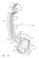
- a straight header of the fuel injector conduit extends transversely (in an axially aftwardly direction) away from the outlet end of the middle portion and leads to an annular main nozzle. Radial thermal growth of the feed strip is accommodated by deflection of bending arms of the strip that are fully or partially transverse to or deflect substantially transversely to the middle portion.
- the straight header is a first bending arm A1 and it is the longest of the bending arms.
- the middle portion is slightly bowed and has a radius of curvature greater than a length of the middle portion.
- the middle portion is slightly bowed for ease of installation.
- the feed strip has at least one acute bend between the inlet end and the middle portion and a bend between the outlet end and the middle portion.
- the acute bend has radially inner and outer arms, respectively having second and third bending arm lengths.
- the inner and outer arms are angularly spaced apart by an acute angle.
- the second and third bending arm lengths are fully or partially transverse to or deflect substantially transversely to the middle portion.
- the feed strip has fuel inlet holes in the inlet end connected to the internal fuel flow passages. The inlet end is fixed within a valve housing.
- the annular main nozzle is fluidly connected to the outlet end of the feed strip and integrally formed with the feed strip from the single bonded together pair of lengthwise extending plates.
- the internal fuel flow passages extend through the feed strip and the annular main nozzle.
- Annular legs extend circumferentially from at least a first one of the internal fuel flow passages through the main nozzle.
- Spray orifices extend from the annular legs through at least one of the plates.
- the annular legs may have waves.
- the annular legs may include clockwise and counterclockwise extending annular legs.
- the clockwise and counterclockwise extending annular legs may have parallel first and second waves, respectively, and the spray orifices may be located in alternating ones of the first and second waves so as to be substantially aligned along a circle.
- the conduit includes a pilot nozzle circuit which includes clockwise and counterclockwise extending pilot legs extending circumferentially from at least a second one of the internal fuel flow passages through the main nozzle.
- the invention includes a fuel injector including an upper valve housing, a hollow stem depending from the housing, at least one fuel nozzle assembly supported by the stem, and the fuel injector conduit extending between the housing through the stem to the nozzle assembly.
- the injector may further include a main mixer having an annular main housing with openings aligned with the spray orifices.
- An annular cavity is defined within the main housing and the main nozzle is supported by the main housing within the annular cavity.
- An annular slip joint seal is disposed in each set of the openings aligned with each one of the spray orifices.
- the housing may include inner and outer heat shields and the inner heat shield may further include inner and outer walls and an annular gap therebetween such that the openings pass through the inner and outer heat shields.
- the annular slip joint seal may be attached to the inner wall of the inner heat shield.
- the invention also provides a fuel injector having an annular main nozzle, a main mixer having an annular main housing with openings aligned with spray orifices in a main nozzle, and an annular cavity defined within the main housing.
- the main nozzle is received within the annular cavity and an annular slip joint seal is disposed in each set of the openings aligned with each one of the spray orifices.
- the housing may further include inner and outer heat shields, respectively, and the inner heat shield may include inner and outer walls with an annular gap therebetween.
- the openings may pass through the inner and outer heat shields, 196) and the annular slip joint seal may be attached to the inner wall of the inner heat shield.
- the feed strip of the present invention has good relative displacement flexibility along the axis of the stem and low stresses caused by differential thermal expansion due to the extreme temperatures to which the nozzle is exposed.
- the present invention provides for a fuel conduit that allows the use of a smaller envelope for hollow stem which serves as a heat shield for the conduit.
- the hollow stem in turn, has a small circumferential width in the flow and, therefore, lowers drag and associated flow losses making for a more aerodynamically efficient design.
- FIG. 1 Illustrated in FIG. 1 is an exemplary embodiment of a combustor 16 including a combustion zone 18 defined between and by annular, radially outer and radially inner liners 20 and 22, respectively.
- the outer and inner liners 20 and 22 are located radially inwardly of an annular combustor casing 26 which extends circumferentially around outer and inner liners 20 and 22.
- the combustor 16 also includes an annular dome 34 mounted upstream from outer and inner liners 20 and 22.
- the dome 34 defines an upstream end 36 of the combustion zone 18 and a plurality of mixer assemblies 40 (only one is illustrated) are spaced circumferentially around the dome 34.
- Each mixer assembly 40 supports pilot and main nozzles 58 and 59, respectively, and together with the pilot and main nozzles deliver a mixture of fuel and air to the combustion zone 18.
- Each mixer assembly 40 has an axis of revolution 52 about which the pilot and main nozzles 58 and 59 are circumscribed.
- an exemplary embodiment of a fuel injector 10 of the present invention has a fuel nozzle assembly 12 (more than one radially spaced apart nozzle assemblies may be used) that includes the pilot and main nozzles 58 and 59, respectively, for directing fuel into the combustion zone of a combustion chamber of a gas turbine engine.
- the fuel injector 10 includes a nozzle mount or flange 30 adapted to be fixed and sealed to the combustor casing 26.
- a hollow stem 32 is integral with or fixed to the flange 30 (such as by brazing or welding) and supports the fuel nozzle assembly 12 and the mixer assembly 40.
- the hollow stem 32 has an inlet assembly 41 disposed above or within an open upper end of a chamber 39 and is integral with or fixed to flange 30 such as by brazing.
- Inlet assembly 41 may be part of a valve housing 43 with the hollow stem 32 depending from the housing.
- the housing 43 is designed to be fluidly connected to a fuel manifold 44 illustrated schematically in FIG. 7 to direct fuel into the injector 10.
- the inlet assembly 41 is operable to receive fuel from the fuel manifold 44.
- the inlet assembly 41 includes fuel valves 45 to control fuel flow through fuel circuits 102 in the fuel nozzle assembly 12.
- the inlet assembly 41 as illustrated in FIG. 2 is integral with or fixed to and located radially outward of the flange 30 and houses fuel valve receptacles 19 for housing the fuel valves 45.
- the nozzle assembly 12 includes the pilot and main nozzles 58 and 59, respectively. Generally, the pilot and main nozzles 58 and 59 are used during normal and extreme power situations while only the pilot nozzle is used during start-up and part power operation.
- a flexible fuel injector conduit 60 having a single elongated feed strip 62 is used to provide fuel from the inlet assembly 41 to the nozzle assembly 12.
- the feed strip 62 is a flexible feed strip formed from a material which can be exposed to high temperatures, such as during brazing in a manufacturing process, without being adversely affected.
- the feed strip 62 has a single bonded together pair of lengthwise extending first and second plates 76, 78.
- Each of the first and second plates 76, 78 has a single row 80 of widthwise spaced apart and lengthwise extending parallel grooves 84.
- the plates are bonded together such that opposing grooves 84 in each of the plates are aligned forming internal fuel flow passages 90 through the length L of the feed strip 62 from an inlet end 66 to an outlet end 69 of the feed strip 62.
- a pilot nozzle extension 54 extends aftwardly from the main nozzle 59 and is fluidly connected to a fuel injector tip 57 of the pilot nozzle 58 by the pilot feed tube 56 as further illustrated in FIG. 4.
- the feed strip 62 feeds the main nozzle 59 as illustrated in FIG. 3.
- the pilot nozzle extension 54 and the pilot feed tube 56 are generally angularly separated about the axis of revolution 52 by an angle AA illustrated in FIG. 8.
- the feed strip 62 has a substantially straight radially extending middle portion 64 between the inlet end 66 and the outlet end 69.
- a straight header 104 of the fuel injector conduit 60 extends transversely (in an axially aftwardly direction) away from the outlet end 69 of the middle portion 64 and leads to an annular main nozzle 59 which is secured thus preventing deflection.
- a thermal growth length LTG of the feed strip 62 is subject to radial thermal growth which is accommodated by deflection of bending arms AN of the strip that are fully or partially transverse to or deflect substantially transversely to the middle portion 64.
- the longest of the bending arms AN is denoted as a first bending arm A1 and is the straight header 104.
- the bending arms AN have bending arm moment lengths LN that are fully or partially transverse to the middle portion 64 and first bending arm A1 has a bending arm moment length L1.
- the middle portion 64 is slightly bowed and has a radius of curvature R greater than a middle portion length ML of the middle portion 64 as illustrated in FIGS. 8 and 9.
- the illustrated embodiment of the invention also includes at least one acute bend 65 between the inlet end 66 and the middle portion 64 and a bend 68 between the middle portion 64 and the outlet end 69.
- the acute bend 65 has radially inner and outer arms 75 and 77, respectively, which operate as second and third bending arms A2 and A3, that are fully or partially transverse to or deflect substantially transversely to the middle portion 64.
- the inner and outer arms 75 and 77 are angularly spaced apart by an acute angle 79.
- the second and third bending arms A2 and A3 have second and third bending arm lengths L2 and L3.
- the second and third transverse bending arms A2 and A3 have respective second and third transverse bending arm moment lengths L2 and L3 transverse to and operable to deflect substantially transversely to the middle portion 64.
- the bend 68 transitions the strip 62 from the middle portion 64 to a header 104 of the fuel injector conduit 60.
- the inlet end 66 is fixed and restrained from thermal growth induced movement within a valve housing 43.
- the fuel injector conduit 60 is designed to have a maximum allowable low cycle fatigue LCF stress.
- LCF life analysis of thermal-strain induced stress should be conducted to determine a LCF maximum stress SM.
- One such LCF life analysis is to use strain controlled LCF data. Cyclic material testing is performed using the same peak strain on each cycle. This mimics the thermal stress vs. strain situation on the actual part. Overall peak strain is constant for a given thermal cycle while actual peak stress decreases with localized plastic flow.
- Present day methods include use of load controlled LCF data for rotating parts in which the peak stress is driven more by centrifugal acceleration and for pressure vessels in which peak stress may be driven by pressure.
- the load control cyclic test keeps load constant on each cycle so that local peak stress is constant or even increasing as plastic flow occurs and the net cross-sectional area decreases. This mimics those applications because in both cases, the load (centrifugal and/or pressure) is typically not relieved and is constant as plastic flow occurs.
- the fuel injector conduit 60 is life limited by thermal strain, thus, strain controlled data should be used for life cycle analyses.
- One method to perform thermal strain LCF life analysis is to use the average of a pseudo-elastic stress range [(maximum stress - minimum stress)/2] as a mean stress, and (maximum stress - mean stress) as an alternating stress.
- the data is presented in the form of cycles to crack initiation (x-axis) vs. alternating pseudo-elastic stress (y-axis) see FIG. 10.
- Inconel 600 is one material presently being studied for use.
- the data illustrated in FIG. 10 is an estimate for Inconel 625 at 250 degrees F.
- the material properties related to this invention for Inconel 600 are thought to be similar to those of Inconel 625.
- the data is in statistical format, i.e. an average curve CA, a -3sigma curve C3, and a 95/99 curve C9.
- the 95/99 curve represents a worst-case material and is typically used for design purposes.
- the 95/99 curve represents the stress level that will not result in crack initiation for the given amount of cycles for 99% of coupons tested, with 95% confidence level. This curve is typically -5 to -6 sigma below the average curve.
- a stretch design goal for engine cold parts such as may be found on a CFM56 cold parts is 3 service intervals of 15,000 full thermal cycles (FTCs) each, which represents over 20 years of service.
- FTCs full thermal cycles
- the worse case FTC is assumed to occur on every flight, and a goal of 50,000 cycles, with 50% stress margin is used in the exemplary analysis. This is equivalent to an alternating pseudo-stress less than 67% of the 95/99 value (65 ksi) at 50,000 cycles. Therefore, for IN625 the peak concentrated allowable bending stress smax is 2 x 43.5 or 87 ksi.
- ⁇ MAX 3xL1xExHxLTGx(THx ⁇ H-TCx ⁇ C) 2x(L 1 3 +L 2 3 +....LN 3 )
- Equation 1 defines a change
- LTG is in terms of change from room temperature to design operating conditions difference between the hot housing denoted by TH and the colder feed strip 62.
- the inlet end 66 is fixed and restrained from thermal growth induced movement within the valve housing 43.
- Equation 3 in FIG. 10 defines a relationship between the peak concentrated allowable bending stress smax which would occur in the first bending arm A1 which has a bending arm moment length L1.
- the bending arm moment lengths LN are chosen such that smax in equation 4 does not exceed a predetermined design value based on design considerations disclosed above which in the exemplary embodiment is about 87 ksi.
- the header 104 is generally parallel to the axis of revolution 52 and leads to the main nozzle 59.
- the shape of the feed strip 62 and, in particular, the middle portion 64 allows expansion and contraction of the feed strip in response to thermal changes in the combustion chamber, while reducing mechanical stresses within the injector.
- the shape of the feed strip helps reduce or eliminate the need for additional heat shielding of the stem portion in many applications, although in some high-temperature situations an additional heat shield may still be necessary or desirable.
- the term strip means that the feed strip 62 has an elongated essentially flat shape with first and second side surfaces 70 and 71 that are substantially parallel and oppositely facing from each other.
- the strip 62 includes substantially parallel oppositely-facing first and second edges 72 and 73 that are substantially perpendicular to the first and second side surfaces 70 and 71.
- the strip has a rectangular shape 74 in cross-section (as compared to the cylindrical shape of a typical fuel tube), although this shape could vary depending upon manufacturing requirements and techniques.
- the feed strip may have a sufficient radius of curvature R of the middle portion 64 to allow the strip to easily be inserted and withdrawn from the hollow stem 32 without providing undue stress on the strip.
- the strip should be sized so as to prevent or avoid causing the strip to exhibit resonant behavior in response to combustion system stimuli.
- the strip's shape and size appropriate for the particular application can be determined by experimentation and analytical modeling and/or resonant frequency testing.
- the inlets 63 at the inlet end 66 of the feed strip 62 are in fluid flow communication or fluidly connected with first, second, third, or fourth inlet ports 46, 47, 48, and 49, respectively, in the inlet assembly 41 to direct fuel into the feed strips.
- the inlet ports feed the multiple internal fuel flow passages 90 down the length L of the feed strip 62 to the pilot nozzle 58 and main nozzle 59 in the nozzle assembly 12 as well as provide cooling circuits for thermal control in the nozzle assembly.
- the header 104 of the nozzle assembly 12 receives fuel from the feed strip 62 and conveys the fuel to the main nozzle 59 and, where incorporated, to the pilot nozzle 58 through the fuel circuits 102 as illustrated in FIGS. 7 and 8.
- the feed strip 62, the main nozzle 59, and the header 104 therebetween are integrally constructed from the lengthwise extending first and second plates 76 and 78.
- the main nozzle 59 and the header 104 may be considered to be elements of the feed strip 62.
- the fuel flow passages 90 of the fuel circuits 102 run through the feed strip 62, the header 104, and the main nozzle 59.
- the fuel passages 90 of the fuel circuits 102 lead to spray orifices 106 and through the pilot nozzle extension 54 which is operable to be fluidly connected to the pilot feed tube 56 to feed the pilot nozzle 58 as illustrated in FIG. 4.
- the parallel grooves 84 of the fuel flow passages 90 of the fuel circuits 102 are etched into adjacent surfaces 210 of the first and second plates 76 and 78 as illustrated in FIGS. 5 and 6.
- the fuel circuits 102 include first and second main nozzle circuits 280 and 282 each of which include clockwise and counterclockwise extending annular legs 284 and 286, respectively, in the main nozzle 59.
- the spray orifices 106 extend from the annular legs 284 and 286 through one or both of the first and second plates 76 and 78. In the exemplary embodiment, the spray orifices 106 radially extend outwardly through the first plate 76 of the main nozzle 59 which is the radially outer one of the plates.
- the clockwise and counterclockwise extending annular legs 284 and 286 have parallel first and second waves 290 and 292, respectively.
- the spray orifices 106 are located in alternating ones of the first and second waves 290 and 292 so as to be substantially circularly aligned along a circle 300.
- the fuel circuits 102 also include a looped pilot nozzle circuit 288 which feeds the pilot nozzle extension 54.
- the looped pilot nozzle circuit 288 includes clockwise and counterclockwise extending annular pilot legs 294 and 296, respectively, in the main nozzle 59.
- the internal fuel flow passages 90 down the length of the feed strips 62 are used to feed fuel to the fuel circuits 102.
- Fuel going into each of the internal fuel flow passages 90 in the feed strips 62 and the header 104 into the pilot and main nozzles 58 and 59 is controlled by fuel valves 45 illustrated by the inlet assembly 41 being part of the valve's housing and further illustrated schematically in FIG. 7.
- the header 104 of the nozzle assembly 12 receives fuel from the feed strips 62 and conveys the fuel to the main nozzle 59.
- the main nozzle 59 is annular and has a cylindrical shape or configuration.
- the flow passages, openings and various components of the spray devices in plates 76 and 78 can be formed in any appropriate manner such as by etching and, more specifically, chemical etching.
- the chemical etching of such plates should be known to those skilled in the art and is described for example in U.S. Patent No. 5,435,884.
- the etching of the plates allows the forming of very fine, well-defined, and complex openings and passages, which allow multiple fuel circuits to be provided in the feed strips 62 and main nozzle 59 while maintaining a small cross-section for these components.
- the plates 76 and 78 can be bonded together in surface-to-surface contact with a bonding process such as brazing or diffusion bonding. Such bonding processes are well-known to those skilled in the art and provides a very secure connection between the various plates. Diffusion bonding is particularly useful as it results in grain boundary growth across an original bond interface between adjacent layers providing a mechanically good joint.
- each mixer assembly 40 includes a pilot mixer 142, a main mixer 144, and a centerbody 143 extending therebetween.
- the centerbody 143 defines a chamber 150 that is in flow communication with, and downstream from, the pilot mixer 142.
- the pilot nozzle 58 is supported by the centerbody 143 within the chamber 150.
- the pilot nozzle 58 is designed for spraying droplets of fuel downstream into the chamber 150.
- the main mixer 144 includes first and second main swirlers 180 and 182 located upstream from spray orifices 106.
- the pilot mixer 142 includes a pair of concentrically mounted pilot swirlers 160.
- the swirlers 160 are axial swirlers and include an inner pilot swirler 162 and an outer pilot swirler 164.
- the inner pilot swirler 162 is annular and is circumferentially disposed around the pilot nozzle 58.
- Each of the inner and outer pilot swirlers 162 and 164 includes a plurality of inner and outer pilot swirling vanes 166 and 168, respectively, positioned upstream from pilot nozzle 58.
- An annular pilot splitter 170 is radially disposed between the inner and outer pilot swirlers 162 and 164 and extends downstream from the inner and outer pilot swirlers 162 and 164.
- the pilot splitter 170 is designed to separate airflow traveling through inner pilot swirler 162 from airflow flowing through the outer pilot swirler 164.
- Splitter 170 has a converging-diverging inner surface 174 which provides a fuel-filming surface during engine low power operations.
- the splitter 170 also controls axial velocities of air flowing through the pilot mixer 142 to control recirculation of hot gases.
- the inner pilot swirler vanes 166 swirl air flowing therethrough in the same direction as air flowing through the outer pilot swirler vanes 168. In another embodiment, the inner pilot swirler vanes 166 swirl air flowing therethrough in a first circumferential direction that is opposite a second circumferential direction that the outer pilot swirler vanes 168 swirl air flowing therethrough.
- the main mixer 144 includes an annular main housing 190 that defines an annular cavity 192.
- the main mixer 144 is concentrically aligned with respect to the pilot mixer 142 and extends circumferentially around the pilot mixer 142.
- the annular main nozzle 59 is circumferentially disposed between the pilot mixer 142 and the main mixer 144. More specifically, main nozzle 59 extends circumferentially around the pilot mixer 142 and is radially located between the centerbody 143 and the main housing 190.
- the housing 190 includes inner and outer heat shields 194 and 196.
- the inner heat shield 194 includes inner and outer walls 202 and 204, respectively, and a 360 degree annular gap 200 therebetween.
- the inner and outer heat shields 194 and 196 each include a plurality of openings 206 aligned with the spray orifices 106.
- the inner and outer heat shields 194 and 196 are fixed to the stem 32 in an appropriate manner, such as by welding or brazing.
- the main nozzle 59 and the spray orifices 106 inject fuel radially outwardly into the main mixer cavity 192 though the openings 206 in the inner and outer heat shields 194 and 196.
- An annular slip joint seal 208 is disposed in each set of the openings 206 in the inner heat shield 194 aligned with each one of the spray orifices 106 to prevent crossflow through the annular gap 200.
- the annular slip joint seal 208 is attached to the inner wall 202 of the inner heat shield 194 by a braze or other method.
- the annular slip joint seal 208 disposed in each of the openings 206 in the inner heat shield 194 to prevent crossflow through the annular gap 200 may be used with other types of fuel injectors.
Landscapes
- Engineering & Computer Science (AREA)
- Chemical & Material Sciences (AREA)
- Combustion & Propulsion (AREA)
- Mechanical Engineering (AREA)
- General Engineering & Computer Science (AREA)
- Fuel-Injection Apparatus (AREA)
Applications Claiming Priority (2)
| Application Number | Priority Date | Filing Date | Title |
|---|---|---|---|
| US161911 | 1993-12-08 | ||
| US10/161,911 US6718770B2 (en) | 2002-06-04 | 2002-06-04 | Fuel injector laminated fuel strip |
Publications (2)
| Publication Number | Publication Date |
|---|---|
| EP1369644A1 true EP1369644A1 (fr) | 2003-12-10 |
| EP1369644B1 EP1369644B1 (fr) | 2011-05-04 |
Family
ID=29549304
Family Applications (1)
| Application Number | Title | Priority Date | Filing Date |
|---|---|---|---|
| EP03253522A Expired - Fee Related EP1369644B1 (fr) | 2002-06-04 | 2003-06-04 | Bande laminée d'un injecteur de carburant |
Country Status (5)
| Country | Link |
|---|---|
| US (1) | US6718770B2 (fr) |
| EP (1) | EP1369644B1 (fr) |
| JP (1) | JP4505654B2 (fr) |
| CN (1) | CN100416063C (fr) |
| DE (1) | DE60336958D1 (fr) |
Cited By (9)
| Publication number | Priority date | Publication date | Assignee | Title |
|---|---|---|---|---|
| US6718770B2 (en) | 2002-06-04 | 2004-04-13 | General Electric Company | Fuel injector laminated fuel strip |
| US6898938B2 (en) | 2003-04-24 | 2005-05-31 | General Electric Company | Differential pressure induced purging fuel injector with asymmetric cyclone |
| EP1548361A1 (fr) * | 2003-12-25 | 2005-06-29 | Kawasaki Jukogyo Kabushiki Kaisha | Méthode d'alimentation en carburant et circuit d'alimentation |
| WO2006120168A2 (fr) * | 2005-05-11 | 2006-11-16 | Siemens Aktiengesellschaft | Dispositif d'alimentation en carburant d'une turbine a gaz comportant une zone de deviation |
| GB2438316A (en) * | 2006-05-19 | 2007-11-21 | Delavan Inc | Apparatus and Method to Compensate for Differential Thermal Growth of Injector Components |
| EP1956296A1 (fr) * | 2007-02-12 | 2008-08-13 | Siemens Aktiengesellschaft | Module d'alimentation en carburant |
| EP1798475A3 (fr) * | 2005-12-13 | 2009-11-25 | Kawasaki Jukogyo Kabushiki Kaisha | Dispositif d'injection de carburant pour turbine à gaz |
| EP1426690A3 (fr) * | 2002-12-03 | 2010-08-25 | General Electric Company | Procédé et dispositif pour la réduction des émissions d'une chambre de combustion |
| EP3128239A3 (fr) * | 2015-08-03 | 2017-02-22 | Delavan, Inc. | Alimentation de carburant |
Families Citing this family (65)
| Publication number | Priority date | Publication date | Assignee | Title |
|---|---|---|---|---|
| US7249460B2 (en) * | 2002-01-29 | 2007-07-31 | Nearhoof Jr Charles F | Fuel injection system for a turbine engine |
| US7007864B2 (en) * | 2002-11-08 | 2006-03-07 | United Technologies Corporation | Fuel nozzle design |
| US6898926B2 (en) * | 2003-01-31 | 2005-05-31 | General Electric Company | Cooled purging fuel injectors |
| US6959535B2 (en) * | 2003-01-31 | 2005-11-01 | General Electric Company | Differential pressure induced purging fuel injectors |
| US7028483B2 (en) * | 2003-07-14 | 2006-04-18 | Parker-Hannifin Corporation | Macrolaminate radial injector |
| DE10345342A1 (de) * | 2003-09-19 | 2005-04-28 | Engelhard Arzneimittel Gmbh | Verfahren zur Herstellung eines lagerstabilen Extraktes aus Efeublättern, sowie ein nach diesem Verfahren hergestellter Extrakt |
| US7036302B2 (en) * | 2004-03-15 | 2006-05-02 | General Electric Company | Controlled pressure fuel nozzle system |
| FR2867552B1 (fr) * | 2004-03-15 | 2008-07-11 | Gen Electric | Injecteur de carburant a pression regulee |
| US6955040B1 (en) * | 2004-03-31 | 2005-10-18 | General Electric Company | Controlled pressure fuel nozzle injector |
| JP2005283001A (ja) * | 2004-03-30 | 2005-10-13 | Osaka Gas Co Ltd | ガスタービンエンジン用燃焼装置 |
| EP1724528A1 (fr) * | 2005-05-13 | 2006-11-22 | Siemens Aktiengesellschaft | Procédé et dispositif de régulation du fonctionnement dans une chambre de combustion d'une turbine à gaz |
| US7624576B2 (en) * | 2005-07-18 | 2009-12-01 | Pratt & Whitney Canada Corporation | Low smoke and emissions fuel nozzle |
| US7921649B2 (en) * | 2005-07-21 | 2011-04-12 | Parker-Hannifin Corporation | Mode suppression shape for beams |
| US7788927B2 (en) * | 2005-11-30 | 2010-09-07 | General Electric Company | Turbine engine fuel nozzles and methods of assembling the same |
| US7506510B2 (en) * | 2006-01-17 | 2009-03-24 | Delavan Inc | System and method for cooling a staged airblast fuel injector |
| US7762070B2 (en) * | 2006-05-11 | 2010-07-27 | Siemens Energy, Inc. | Pilot nozzle heat shield having internal turbulators |
| US8001761B2 (en) * | 2006-05-23 | 2011-08-23 | General Electric Company | Method and apparatus for actively controlling fuel flow to a mixer assembly of a gas turbine engine combustor |
| US8312727B2 (en) * | 2006-09-26 | 2012-11-20 | Parker-Hannifin Corporation | Vibration damper |
| US8020384B2 (en) * | 2007-06-14 | 2011-09-20 | Parker-Hannifin Corporation | Fuel injector nozzle with macrolaminate fuel swirler |
| JP4995657B2 (ja) * | 2007-07-23 | 2012-08-08 | ゼネラル・エレクトリック・カンパニイ | ガスタービンエンジン燃焼器のミキサ組立体への燃料流量を能動的に制御するための装置 |
| FR2919672B1 (fr) * | 2007-07-30 | 2014-02-14 | Snecma | Injecteur de carburant dans une chambre de combustion de turbomachine |
| FR2919898B1 (fr) * | 2007-08-10 | 2014-08-22 | Snecma | Injecteur multipoint pour turbomachine |
| US7712313B2 (en) * | 2007-08-22 | 2010-05-11 | Pratt & Whitney Canada Corp. | Fuel nozzle for a gas turbine engine |
| DE102007050276A1 (de) * | 2007-10-18 | 2009-04-23 | Rolls-Royce Deutschland Ltd & Co Kg | Magervormischbrenner für ein Gasturbinentriebwerk |
| US7926178B2 (en) * | 2007-11-30 | 2011-04-19 | Delavan Inc | Method of fuel nozzle construction |
| US8061142B2 (en) * | 2008-04-11 | 2011-11-22 | General Electric Company | Mixer for a combustor |
| US9188341B2 (en) * | 2008-04-11 | 2015-11-17 | General Electric Company | Fuel nozzle |
| US8806871B2 (en) * | 2008-04-11 | 2014-08-19 | General Electric Company | Fuel nozzle |
| US20090255120A1 (en) * | 2008-04-11 | 2009-10-15 | General Electric Company | Method of assembling a fuel nozzle |
| US20090255256A1 (en) * | 2008-04-11 | 2009-10-15 | General Electric Company | Method of manufacturing combustor components |
| US9046039B2 (en) | 2008-05-06 | 2015-06-02 | Rolls-Royce Plc | Staged pilots in pure airblast injectors for gas turbine engines |
| US8096135B2 (en) * | 2008-05-06 | 2012-01-17 | Dela Van Inc | Pure air blast fuel injector |
| US9464808B2 (en) * | 2008-11-05 | 2016-10-11 | Parker-Hannifin Corporation | Nozzle tip assembly with secondary retention device |
| US20100263382A1 (en) * | 2009-04-16 | 2010-10-21 | Alfred Albert Mancini | Dual orifice pilot fuel injector |
| JP4815513B2 (ja) * | 2009-07-06 | 2011-11-16 | 川崎重工業株式会社 | ガスタービン燃焼器 |
| FR2951245B1 (fr) * | 2009-10-13 | 2013-05-17 | Snecma | Dispositif d'injection multi-point pour une chambre de combustion de turbomachine |
| US8726668B2 (en) | 2010-12-17 | 2014-05-20 | General Electric Company | Fuel atomization dual orifice fuel nozzle |
| US8387391B2 (en) * | 2010-12-17 | 2013-03-05 | General Electric Company | Aerodynamically enhanced fuel nozzle |
| US20120151928A1 (en) * | 2010-12-17 | 2012-06-21 | Nayan Vinodbhai Patel | Cooling flowpath dirt deflector in fuel nozzle |
| US8967206B2 (en) | 2010-12-22 | 2015-03-03 | Delavan Inc. | Flexible fluid conduit |
| US20120180494A1 (en) * | 2011-01-14 | 2012-07-19 | General Electric Company | Turbine fuel nozzle assembly |
| EP2489939A1 (fr) * | 2011-02-18 | 2012-08-22 | Siemens Aktiengesellschaft | Chambre de combustion dotée d'une section de paroi et d'un élément de bord |
| US20120227408A1 (en) * | 2011-03-10 | 2012-09-13 | Delavan Inc. | Systems and methods of pressure drop control in fluid circuits through swirling flow mitigation |
| US9228741B2 (en) | 2012-02-08 | 2016-01-05 | Rolls-Royce Plc | Liquid fuel swirler |
| US9383097B2 (en) | 2011-03-10 | 2016-07-05 | Rolls-Royce Plc | Systems and method for cooling a staged airblast fuel injector |
| US9310073B2 (en) * | 2011-03-10 | 2016-04-12 | Rolls-Royce Plc | Liquid swirler flow control |
| EP2711633A1 (fr) * | 2012-09-21 | 2014-03-26 | Siemens Aktiengesellschaft | Elément de retenue pour maintenir un bouclier de protection thermique et procédé de refroidissement de la structure porteuse d'un bouclier thermique |
| EP2711634A1 (fr) * | 2012-09-21 | 2014-03-26 | Siemens Aktiengesellschaft | Bouclier thermique avec une structure porteuse et procédé de refroidissement de la structure porteuse |
| DE102013204307A1 (de) | 2013-03-13 | 2014-09-18 | Siemens Aktiengesellschaft | Strahlbrenner mit Kühlkanal in der Grundplatte |
| FR3003632B1 (fr) * | 2013-03-19 | 2016-10-14 | Snecma | Systeme d'injection pour chambre de combustion de turbomachine comportant une paroi annulaire a profil interne convergent |
| US9556795B2 (en) * | 2013-09-06 | 2017-01-31 | Delavan Inc | Integrated heat shield |
| JP6210810B2 (ja) * | 2013-09-20 | 2017-10-11 | 三菱日立パワーシステムズ株式会社 | デュアル燃料焚きガスタービン燃焼器 |
| BR112016011777A2 (pt) * | 2013-11-27 | 2017-08-08 | Gen Electric | Aparelhos de bocal de combustível |
| GB201321193D0 (en) | 2013-12-02 | 2014-01-15 | Rolls Royce Plc | A combustion chamber assembly |
| CA2933539C (fr) | 2013-12-23 | 2022-01-18 | General Electric Company | Injecteur de carburant dote de structures de support souples |
| CA2933536C (fr) | 2013-12-23 | 2018-06-26 | General Electric Company | Structure d'injecteur de carburant pour injection a assistance pneumatique |
| US20150285502A1 (en) * | 2014-04-08 | 2015-10-08 | General Electric Company | Fuel nozzle shroud and method of manufacturing the shroud |
| US9453461B2 (en) * | 2014-12-23 | 2016-09-27 | General Electric Company | Fuel nozzle structure |
| US10502425B2 (en) * | 2016-06-03 | 2019-12-10 | General Electric Company | Contoured shroud swirling pre-mix fuel injector assembly |
| CN106767230B (zh) * | 2016-11-09 | 2018-11-27 | 珠海保税区摩天宇航空发动机维修有限公司 | 一种cfm56航空发动机低压涡轮叶片封严齿槽口尺寸检验工具 |
| US11098900B2 (en) * | 2017-07-21 | 2021-08-24 | Delavan Inc. | Fuel injectors and methods of making fuel injectors |
| US10961967B1 (en) | 2017-12-12 | 2021-03-30 | Microfabrica Inc. | Fuel injector systems, fuel injectors, fuel injector nozzles, and methods for making fuel injector nozzles |
| US10934940B2 (en) * | 2018-12-11 | 2021-03-02 | General Electric Company | Fuel nozzle flow-device pathways |
| FR3107564B1 (fr) * | 2020-02-24 | 2022-12-02 | Safran Helicopter Engines | Ensemble de combustion pour turbomachine |
| DE102022207492A1 (de) | 2022-07-21 | 2024-02-01 | Rolls-Royce Deutschland Ltd & Co Kg | Düsenvorrichtung zur Zugabe zumindest eines gasförmigen Kraftstoffes und eines flüssigen Kraftstoffes, Set, Zuleitungssystem und Gasturbinenanordnung |
Citations (3)
| Publication number | Priority date | Publication date | Assignee | Title |
|---|---|---|---|---|
| US5577386A (en) * | 1994-06-20 | 1996-11-26 | Societe Nationale D'etude Et De Construction De Moteurs D'aviation S.N.E.C.M.A. | System for cooling a high power fuel injector of a dual injector |
| US6076356A (en) * | 1996-03-13 | 2000-06-20 | Parker-Hannifin Corporation | Internally heatshielded nozzle |
| US6321541B1 (en) * | 1999-04-01 | 2001-11-27 | Parker-Hannifin Corporation | Multi-circuit multi-injection point atomizer |
Family Cites Families (17)
| Publication number | Priority date | Publication date | Assignee | Title |
|---|---|---|---|---|
| US3612397A (en) * | 1969-07-24 | 1971-10-12 | Ronald K Pearson | Fluid injector |
| GB1563124A (en) * | 1975-12-24 | 1980-03-19 | Gen Electric | Gas turbine fuel injection systems |
| US4070826A (en) * | 1975-12-24 | 1978-01-31 | General Electric Company | Low pressure fuel injection system |
| US4735044A (en) * | 1980-11-25 | 1988-04-05 | General Electric Company | Dual fuel path stem for a gas turbine engine |
| US4499735A (en) * | 1982-03-23 | 1985-02-19 | The United States Of America As Represented By The Secretary Of The Air Force | Segmented zoned fuel injection system for use with a combustor |
| US5423178A (en) * | 1992-09-28 | 1995-06-13 | Parker-Hannifin Corporation | Multiple passage cooling circuit method and device for gas turbine engine fuel nozzle |
| US5564271A (en) * | 1994-06-24 | 1996-10-15 | United Technologies Corporation | Pressure vessel fuel nozzle support for an industrial gas turbine engine |
| US5598696A (en) | 1994-09-20 | 1997-02-04 | Parker-Hannifin Corporation | Clip attached heat shield |
| US5761907A (en) | 1995-12-11 | 1998-06-09 | Parker-Hannifin Corporation | Thermal gradient dispersing heatshield assembly |
| CA2248736C (fr) | 1996-03-13 | 2007-03-27 | Parker-Hannifin Corporation | Buse a bouclier thermique interieur |
| FR2753779B1 (fr) * | 1996-09-26 | 1998-10-16 | Systeme d'injection aerodynamique d'un melange air carburant | |
| US6021635A (en) | 1996-12-23 | 2000-02-08 | Parker-Hannifin Corporation | Dual orifice liquid fuel and aqueous flow atomizing nozzle having an internal mixing chamber |
| US6141968A (en) * | 1997-10-29 | 2000-11-07 | Pratt & Whitney Canada Corp. | Fuel nozzle for gas turbine engine with slotted fuel conduits and cover |
| US6141967A (en) * | 1998-01-09 | 2000-11-07 | General Electric Company | Air fuel mixer for gas turbine combustor |
| US6082113A (en) * | 1998-05-22 | 2000-07-04 | Pratt & Whitney Canada Corp. | Gas turbine fuel injector |
| US6523350B1 (en) * | 2001-10-09 | 2003-02-25 | General Electric Company | Fuel injector fuel conduits with multiple laminated fuel strips |
| US6718770B2 (en) | 2002-06-04 | 2004-04-13 | General Electric Company | Fuel injector laminated fuel strip |
-
2002
- 2002-06-04 US US10/161,911 patent/US6718770B2/en not_active Expired - Lifetime
-
2003
- 2003-06-04 CN CNB031363989A patent/CN100416063C/zh not_active Expired - Lifetime
- 2003-06-04 DE DE60336958T patent/DE60336958D1/de not_active Expired - Lifetime
- 2003-06-04 EP EP03253522A patent/EP1369644B1/fr not_active Expired - Fee Related
- 2003-06-04 JP JP2003158780A patent/JP4505654B2/ja not_active Expired - Fee Related
Patent Citations (3)
| Publication number | Priority date | Publication date | Assignee | Title |
|---|---|---|---|---|
| US5577386A (en) * | 1994-06-20 | 1996-11-26 | Societe Nationale D'etude Et De Construction De Moteurs D'aviation S.N.E.C.M.A. | System for cooling a high power fuel injector of a dual injector |
| US6076356A (en) * | 1996-03-13 | 2000-06-20 | Parker-Hannifin Corporation | Internally heatshielded nozzle |
| US6321541B1 (en) * | 1999-04-01 | 2001-11-27 | Parker-Hannifin Corporation | Multi-circuit multi-injection point atomizer |
Cited By (18)
| Publication number | Priority date | Publication date | Assignee | Title |
|---|---|---|---|---|
| US6718770B2 (en) | 2002-06-04 | 2004-04-13 | General Electric Company | Fuel injector laminated fuel strip |
| EP1426690A3 (fr) * | 2002-12-03 | 2010-08-25 | General Electric Company | Procédé et dispositif pour la réduction des émissions d'une chambre de combustion |
| US6898938B2 (en) | 2003-04-24 | 2005-05-31 | General Electric Company | Differential pressure induced purging fuel injector with asymmetric cyclone |
| EP1548361A1 (fr) * | 2003-12-25 | 2005-06-29 | Kawasaki Jukogyo Kabushiki Kaisha | Méthode d'alimentation en carburant et circuit d'alimentation |
| US7104464B2 (en) | 2003-12-25 | 2006-09-12 | Kawasaki Jukogyo Kabushiki Kaisha | Fuel supply method and fuel supply system |
| WO2006120168A2 (fr) * | 2005-05-11 | 2006-11-16 | Siemens Aktiengesellschaft | Dispositif d'alimentation en carburant d'une turbine a gaz comportant une zone de deviation |
| EP1724454A1 (fr) * | 2005-05-11 | 2006-11-22 | Siemens Aktiengesellschaft | Alimentation en combustible avec une zone de détournement pour une turbine à gaz |
| WO2006120168A3 (fr) * | 2005-05-11 | 2007-02-22 | Siemens Ag | Dispositif d'alimentation en carburant d'une turbine a gaz comportant une zone de deviation |
| US8225612B2 (en) | 2005-12-13 | 2012-07-24 | Kawasaki Jukogyo Kabushiki Kaisha | Fuel spraying apparatus of gas turbine engine |
| US7921650B2 (en) | 2005-12-13 | 2011-04-12 | Kawasaki Jukogyo Kabushiki Kaisha | Fuel spraying apparatus of gas turbine engine |
| EP1798475A3 (fr) * | 2005-12-13 | 2009-11-25 | Kawasaki Jukogyo Kabushiki Kaisha | Dispositif d'injection de carburant pour turbine à gaz |
| US7900456B2 (en) | 2006-05-19 | 2011-03-08 | Delavan Inc | Apparatus and method to compensate for differential thermal growth of injector components |
| GB2438316B (en) * | 2006-05-19 | 2011-09-07 | Delavan Inc | Apparatus and method to compensate for differential thermal growth of injector components |
| GB2438316A (en) * | 2006-05-19 | 2007-11-21 | Delavan Inc | Apparatus and Method to Compensate for Differential Thermal Growth of Injector Components |
| WO2008098862A1 (fr) * | 2007-02-12 | 2008-08-21 | Siemens Aktiengesellschaft | Module d'alimentation en carburant |
| EP1956296A1 (fr) * | 2007-02-12 | 2008-08-13 | Siemens Aktiengesellschaft | Module d'alimentation en carburant |
| EP3128239A3 (fr) * | 2015-08-03 | 2017-02-22 | Delavan, Inc. | Alimentation de carburant |
| US10364751B2 (en) | 2015-08-03 | 2019-07-30 | Delavan Inc | Fuel staging |
Also Published As
| Publication number | Publication date |
|---|---|
| US6718770B2 (en) | 2004-04-13 |
| JP4505654B2 (ja) | 2010-07-21 |
| CN1502797A (zh) | 2004-06-09 |
| DE60336958D1 (de) | 2011-06-16 |
| EP1369644B1 (fr) | 2011-05-04 |
| JP2004028566A (ja) | 2004-01-29 |
| CN100416063C (zh) | 2008-09-03 |
| US20030221429A1 (en) | 2003-12-04 |
Similar Documents
| Publication | Publication Date | Title |
|---|---|---|
| EP1369644B1 (fr) | Bande laminée d'un injecteur de carburant | |
| US6523350B1 (en) | Fuel injector fuel conduits with multiple laminated fuel strips | |
| US6321541B1 (en) | Multi-circuit multi-injection point atomizer | |
| EP1471308B1 (fr) | Injecteur de combustible avec système de purge induite par pression différentielle avec cyclone asymétrique | |
| EP1445539B1 (fr) | Purge d'injecteurs de carburant par pression différentielle induite | |
| EP1445540B1 (fr) | Injecteur de carburant autopurgeur refroidi | |
| US6711898B2 (en) | Fuel manifold block and ring with macrolaminate layers | |
| US6955040B1 (en) | Controlled pressure fuel nozzle injector | |
| US20180058404A1 (en) | Fuel injector assembly with wire mesh damper | |
| US7036302B2 (en) | Controlled pressure fuel nozzle system | |
| CA2248736C (fr) | Buse a bouclier thermique interieur | |
| US6915638B2 (en) | Nozzle with fluted tube | |
| US9360217B2 (en) | Flow sleeve for a combustion module of a gas turbine | |
| US6076356A (en) | Internally heatshielded nozzle | |
| EP2902605B1 (fr) | Collecteur de carburant et dispositif d'injecteur de carburant pour turbine à gaz | |
| EP0476927A2 (fr) | Support pour buses d'injection de combustible | |
| US8020384B2 (en) | Fuel injector nozzle with macrolaminate fuel swirler |
Legal Events
| Date | Code | Title | Description |
|---|---|---|---|
| PUAI | Public reference made under article 153(3) epc to a published international application that has entered the european phase |
Free format text: ORIGINAL CODE: 0009012 |
|
| AK | Designated contracting states |
Kind code of ref document: A1 Designated state(s): AT BE BG CH CY CZ DE DK EE ES FI FR GB GR HU IE IT LI LU MC NL PT RO SE SI SK TR |
|
| AX | Request for extension of the european patent |
Extension state: AL LT LV MK |
|
| 17P | Request for examination filed |
Effective date: 20040611 |
|
| AKX | Designation fees paid |
Designated state(s): DE FR GB |
|
| 17Q | First examination report despatched |
Effective date: 20091216 |
|
| GRAP | Despatch of communication of intention to grant a patent |
Free format text: ORIGINAL CODE: EPIDOSNIGR1 |
|
| GRAS | Grant fee paid |
Free format text: ORIGINAL CODE: EPIDOSNIGR3 |
|
| GRAA | (expected) grant |
Free format text: ORIGINAL CODE: 0009210 |
|
| AK | Designated contracting states |
Kind code of ref document: B1 Designated state(s): DE FR GB |
|
| REG | Reference to a national code |
Ref country code: GB Ref legal event code: FG4D |
|
| REF | Corresponds to: |
Ref document number: 60336958 Country of ref document: DE Date of ref document: 20110616 Kind code of ref document: P |
|
| REG | Reference to a national code |
Ref country code: DE Ref legal event code: R096 Ref document number: 60336958 Country of ref document: DE Effective date: 20110616 |
|
| PLBE | No opposition filed within time limit |
Free format text: ORIGINAL CODE: 0009261 |
|
| STAA | Information on the status of an ep patent application or granted ep patent |
Free format text: STATUS: NO OPPOSITION FILED WITHIN TIME LIMIT |
|
| 26N | No opposition filed |
Effective date: 20120207 |
|
| REG | Reference to a national code |
Ref country code: DE Ref legal event code: R097 Ref document number: 60336958 Country of ref document: DE Effective date: 20120207 |
|
| REG | Reference to a national code |
Ref country code: FR Ref legal event code: PLFP Year of fee payment: 14 |
|
| REG | Reference to a national code |
Ref country code: FR Ref legal event code: PLFP Year of fee payment: 15 |
|
| PGFP | Annual fee paid to national office [announced via postgrant information from national office to epo] |
Ref country code: FR Payment date: 20170627 Year of fee payment: 15 Ref country code: GB Payment date: 20170627 Year of fee payment: 15 |
|
| PGFP | Annual fee paid to national office [announced via postgrant information from national office to epo] |
Ref country code: DE Payment date: 20170628 Year of fee payment: 15 |
|
| REG | Reference to a national code |
Ref country code: DE Ref legal event code: R119 Ref document number: 60336958 Country of ref document: DE |
|
| GBPC | Gb: european patent ceased through non-payment of renewal fee |
Effective date: 20180604 |
|
| PG25 | Lapsed in a contracting state [announced via postgrant information from national office to epo] |
Ref country code: FR Free format text: LAPSE BECAUSE OF NON-PAYMENT OF DUE FEES Effective date: 20180630 Ref country code: DE Free format text: LAPSE BECAUSE OF NON-PAYMENT OF DUE FEES Effective date: 20190101 Ref country code: GB Free format text: LAPSE BECAUSE OF NON-PAYMENT OF DUE FEES Effective date: 20180604 |