BACKGROUND OF THE INVENTION
Field of the Invention
The present invention relates to a positive displacement
pump which moves fluid by changing the volume of its pumping
chamber with a piston or diaphragm, and, more particularly,
it relates to a highly reliable pump with a high flow rate.
Description of the Related Art
Conventionally, typical pumps of this type have a check
valve installed between an inlet flow path and a
variable-volume pumping chamber as well as between an outlet
flow path and the pumping chamber, as described, for example,
in Japanese Patent Laid-Open No. 10-220357.
Also, there are pumps which produce unidirectional flow
by utilizing viscous drag and are configured, for example,
as described in Japanese Patent Laid-Open No. 08-312537 such
that fluid resistance is larger in the inlet flow path than
in the outlet flow path when a valve installed in the outlet
flow path is open.
Furthermore, there are pumps which have compression
components configured such that pressure drops vary with the
flow direction both in inlet and outlet flow paths in order
to improve the reliability of the pumps without using movable
parts for valves, as described, for example, in National
Publication of International Patent Application No . 08-506874
and in a paper "An improved valve-less pumpfabricate using
deep reactive ion etching" on pp.479-484 of 1996 IEEE 9th
International Workshop on Micro Electro Mechanical Systems.
However, the configuration described in Japanese Patent
Laid-Open No. 10-220357 requires a check valve both in the
inlet and outlet flow paths and has the problem that a fluid
passing through two check valves suffers high pressure loss.
Also, the check valves, which open and close repeatedly, are
liable to fatigue damage. Besides, the larger the number of
check valves, the lower the reliability.
Also, the configuration described in Japanese Patent
Laid-Open No. 08-312537 needs to increase the fluid resistance
in the inlet flow path in order to reduce back-flow in the
inlet flow path during the discharge stroke of the pump.
Consequently, the suction stroke of the pump, during which
the fluid is introduced into the pumping chamber against the
fluid resistance, becomes considerably longer than the
discharge stroke. This results in a significantly low
frequency of cycling between the pump' s suction and discharge
strokes. With a pump in which a piston or diaphragm moves
up and down, generally the higher the frequency of the up-down
movement, the higher the flow rate and power output, provided
the area of the piston or diaphragm is constant. However,
since the configuration described in Japanese Patent Laid-Open
No.08-312537 allows only low-frequencyoperationas described
above, it cannot implement a small, high-power pump.
Furthermore, in the case of the pump described in National
Publication of International Patent Application No . 08-506874,
since it is configured to produce unidirectional net flow of
the fluid passing through the compression components as the
volume of the pumping chamber increases and-decreases, using
the pressure drops which vary with the flow direction, the
back-flow increases with increases in external pressure (load
pressure) on the outlet side and the pump fails to operate
under high load pressure. According to the paper "An improved
valve-less pumpfabricate using deep reactive ion etching,"
the maximum load pressure is around 0.760 atmosphere.
The present invention has been made to solve the prior
art problems described above. Its object is to provide a small,
lightweight, high-power pump which can operate even under high
load pressure.
SUMMARY OF THE INVENTION
To achieve the above object, pumps according to the present
invention are configured as follows.
A first pump according to the present invention comprises
an actuator which displaces a movable wall such as a piston
or diaphragm; a pumping chamber whose volume can be varied
by the displacement of the movable wall; an inlet flow path
through which a working fluid flows into the pumping chamber;
and an outlet flow path through which the working fluid flows
out of the pumping chamber, wherein the outlet flow path is
in constant communication with the pumping chamber even when
the pump is in operation, combined inertance value of the inlet
flowpath is smaller than combined inertance value of the outlet
flow path, the inlet flow path is equipped with a fluid
resistance element which makes the fluid resistance smaller
when the working fluid flows into the pumping chamber than
when the working fluid flows out, and a return inlet is installed
where the cross-sectional area of the outlet flow path is at
least twice the cross-sectional area of the narrowest part
of the flow path leading out of the pumping chamber of the
pump.
Preferably, the first pump comprises an active valve which
communicates the inlet flow path and outlet flow path of the
pump through the return inlet.
Preferably, the first pump comprises an actuator made
of shape-memory alloy to drive the active valve.
A second pump according to the present invention comprises
an actuator which displaces a movable wall such as a piston
or diaphragm; a pumping chamber whose volume can be varied
by the displacement of the movable wall; a pressure chamber
in communication with the pumping chamber via a connecting
flow path; an inlet flow path through which a working fluid
flows into the pressure chamber; and an outlet flowpath through
which the working fluid flows out of the pressure chamber,
wherein the cross-sectional area of the connecting flow path
is smaller than that of the pumping chamber, the outlet flow
path is in constant communication with the pressure chamber
even when the pump is in operation, combined inertance value
of the inlet flow path is smaller than combined inertance value
of the outlet flow path, and the inlet flow path is equipped
with a fluid resistance element which makes the fluid
resistance smaller when the working fluid flows into the
pressure chamber than when the working fluid flows out.
Preferably, in the second pump, the connecting flow path
is positioned right in front of the fluid resistance element.
Preferably, in the second pump, the outlet flow path is
open in the flow direction of the working fluid flowing out
of the fluid resistance element.
Preferably, in the second pump, the pumping chamber is
filled with fluid, and the connecting flow path is equipped
with a membrane capable of deformation equivalent to volume
changes of the pumping chamber.
A third pump according to the present invention comprises
an actuator which displaces a movable wall such as a piston
or diaphragm; a pumping chamber whose volume can be varied
by the displacement of the movable wall; an inlet flow path
through which a working fluid flows into the pumping chamber;
and an outlet flow path through which the working fluid flows
out of the pumping chamber, wherein the inlet flow path is
equipped with a fluid resistance element which makes the fluid
resistance smaller when the working fluid flows into the
pumping chamber than when the working fluid flows out, and
the outlet flow path has such dimensions that the maximum
kinetic energy stored in the outlet flow path during one cycle
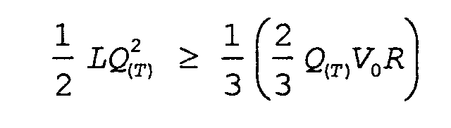
of pump operation is not less than 1/3 the energy consumed
by flow path resistance until the maximum kinetic energy is
stored.
Preferably, if inertance of the outlet flowpath is denoted
by L, if displaced volume when the movable wall is displaced
from bottom dead center to top dead center is denoted by V
0,
if the flow path resistance of the outlet flow path is denoted
by R, and if flow velocity in the outlet flow path when the
actuator produces one cycle of output energy is denoted by
Q(T), the following formula is satisfied.
A fourth pump according to the present invention comprises
an actuator which displaces a movable wall such as a piston
or diaphragm; a pumping chamber whose volume can be varied
by the displacement of the movable wall; an inlet flow path
through which a working fluid flows into the pumping chamber;
and an outlet flow path through which the working fluid flows
out of the pumping chamber, wherein the inlet flow path is
equipped with a fluid resistance element which makes the fluid
resistance smaller when the working fluid flows into the
pumping chamber than when the working fluid flows out, and
compliance of fluid in the outlet flow path is not more than
three times the compliance of the actuator.
Preferably, in the fourth pump, the length of the outlet
flow path is not less than 1/2 of average equivalent diameter.
Preferably, in the fourth pump, the length of the outlet
flow path is 45 mm or less.
Preferably, in the fourth pump, the average diameter of
the outlet flow path is 70 µm or more.
Preferably, in the fourth pump, the average diameter of
the outlet flow path is 3 mm or less.
Preferably, the actuator in the first to fourth pump is
a piezoelectric element.
Preferably, the actuator in the first to fourth pump is
a giant magnetostrictive element.
BRIEF DESCRIPTION OF THE DRAWINGS
FIG. 1 is a diagram showing a longitudinal section of
a pump according to a first embodiment of the present invention;
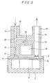
FIG. 2 is a diagram showing a longitudinal section of
the pump according to the first embodiment of the present
invention during reverse operation;
FIG. 3 is a diagram showing a longitudinal section of
a pump according to a second embodiment of the present
invention;
FIG. 4 is a diagram showing a longitudinal section of
a pump according to a third embodiment of the present invention;
FIG. 5 is a diagram showing a longitudinal section of
a pump structure according to a fourth embodiment of the present
invention;
FIG. 6 is a diagram showing state quantities during
operation of the pump according to the fourth embodiment;
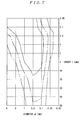
FIG. 7 is a graph showing the relation between the outlet
flowpath size and the ratios between energy stored in inertance
of fluid in an outlet flow path and energy possessed by a
piezoelectric element when the diameters of the piezoelectric
element and diaphragm are 5 mm in the pump according to the
fourth embodiment;
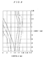
FIG. 8 is a graph showing the relation between the outlet
flow path size and the ratios between energy stored in inertance
of fluid in the outlet flow path and energy possessed by the
piezoelectric element when the diameters of the piezoelectric
element and diaphragm are 10 mm in the pump according to the
fourth embodiment; and
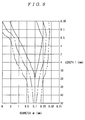
FIG. 9 is a graph showing the relation between the outlet
flow path size and the ratios between energy stored in inertance
of fluid in the outlet flow path and energy possessed by the
piezoelectric element when the diameters of the piezoelectric
element and diaphragm are 2 mm in the pump according to the
fourth embodiment;
DETAILED DESCRIPTION OF THE PREFERRED EMBODIMENTS
Embodiments of a pump according to the present invention
will be described in detail below with reference to the
drawings.
(1) First embodiment
FIG. 1 is a diagram showing a longitudinal section of
a pump according to a first embodiment of the present invention.
In FIG. 1, a circular diaphragm 4 is placed at the bottom of
a cylindrical casing 2. The diaphragm 4 is free to deform
elastically with its rim supported rigidly by the casing 2.
At the bottom of the diaphragm 4, a piezoelectric element 6
which expands and contracts in the vertical direction of the
figure is installed in its own casing 5 as an actuator for
moving the diaphragm 4.
A narrow space between the diaphragm 4 and the top wall
of the casing 2 constitutes a pumping chamber 8. An inlet
flow path 12 and an outlet flow path 14 are open to the pumping
chamber 8, wherein a check valve 10 serving as a fluid resistance
element is installed in the inlet flow path 12. Immediately
downstream of the pumping chamber 8, the outlet flow path 14
has a narrow segment 16. Part of the circumference of the
inlet flow path 12 forms an inlet-side connecting pipe 18 to
connect external piping (not shown) to the pump. Similarly,
part of the circumference of the outlet flow path 14 forms
an outlet-side connecting pipe 20 to connect external piping
(not shown) to the pump.
The narrow segment 16 of the outlet flow path has 1/2
the diameter and 1/4 the cross sectional area of the outlet
flow path 14. The outlet flow path 14 has a return inlet 22,
which is connected to a return outlet 23 in the inlet flow
path via an active valve 24. The active valve 24 is opened
and closed freely by an actuator 26 made of shape-memory alloy.
Next, operation of the pump according to this embodiment
will be described with reference to FIG. 1.
During the pump' s forward operation in which working fluid
flows in the direction of the arrow, the active valve 24 is
kept closed by the actuator 26 made of shape-memory alloy as
shown in FIG. 1. When the diaphragm 4 operates in such a way
as to reduce the volume of the pumping chamber 8, the working
fluid is forced back in the inlet flow path 12, closing the
check valve 10 and thus increasing fluid resistance.
Consequently, little or no working fluid in the inlet flow
path 12 flows out of the inlet flow path 12. On the other
hand, in the outlet flow path 14 with its narrow segment 16,
as the pressure in the pumping chamber 8 rises according to
the compressibility of the working fluid, the flow rate of
the flow out of the pumping chamber 8 increases according to
the differential pressure between the pumping chamber pressure
and load pressure according to inertance value.
When the diaphragm 4 operates in such a way as to increase
the volume of the pumping chamber 8, the pressure in the pumping
chamber 8 lowers. When the pressure in the pumping chamber
8 lowers below external pressure in the inlet flow path 12,
the working fluid flows forward in the inlet flow path 12,
opening the check valve 10 and thus reducing fluid resistance.
Consequently, the flow rate of the flow into the pumping chamber
8 increases according to the differential pressure and the
inertance value of the inlet flow path 12. On the other hand,
in the outlet flow path 14 with its narrow segment 16, the
flow rate of the flow out of the pumping chamber 8 lowers
according to the differential pressure between the load
pressure and pumping chamber pressure according to inertance
value.
Working fluid equal in volume to the working fluid which
flows out of the pumping chamber 8 is fed into the pumping
chamber 8. If this is done when the rate of increase in the
rate of inflow into the inlet flow path 12 is large, this can
be done when decreases in the rate of outflow from the outlet
flow path 14 with its narrow segment 16 are still small
accordingly. Thus, it is advisable to make the combined
inertance value of the inlet flow path 12 smaller than that
of the outlet flow path 14 with its narrow segment 16 as in
the case of this embodiment. The narrow segment 16 of the
outlet flow path has a small cross-sectional area and has a
large inertance value, which is given by L = ρl/S.
On the other hand, working fluid has high flow velocity
where there is a small cross-sectional area because of its
continuity. When the active valve 24 is kept closed by the
actuator 26 made of shape-memory alloy, the energy loss from
the return inlet 22, which corresponds to a branch of a blind
pipe, is proportional to the square of the velocity.
Consequently, according to this embodiment, since the return
inlet 22 is installed in the part of the outlet flow path 14
which is located downstream of the narrow segment 16 and where
the cross-sectional area is four times that of the narrow
segment 16 and the flow velocity is 1/4, the energy loss can
be reduced to 1/16 the energy loss which would occur if the
return inlet were installed in the narrow segment 16 of the
outlet flow path 14. Thus, by installing the return inlet
22 in that part of the outlet flow path 14 whose cross-sectional
area is at least twice the cross-sectional area of the narrowest
part of the flow path leading out of the pumping chamber of
the pump, energy loss across the location of the return inlet
22 can be reduced to 1/4, resulting in a highly efficient pump.
Using the above configuration, a small, lightweight,
high-power pump can be implemented by reducing the number of
fluid resistance elements such as the check valve 10 and thus
reducing pressure loss. Furthermore, since only one fluid
resistance element (check valve 10) is installed, the fluid
actuator will not self-reset when the pump stops if the fluid
actuator equipped with a self-resetting capability remains
stationary.
Next, reverse operation of the pump according to this
invention will be described with reference to FIG. 2. FIG.
2 is a diagram showing a longitudinal section of the pump
according to this embodiment during reverse operation.
First the diaphragm 4 of the pump is stopped and the active
valve 24 is opened by the actuator 26 made of shape-memory
alloy as shown in FIG. 2. When the fluid actuator equipped
with a self-resetting capability is connected to external
piping (not shown) connected to the outlet-side connecting
pipe 20, the pressure in the outlet flow path 14 becomes higher
than the pressure in the inlet flow path 12 because of the
self-resetting capability. Thus, the working fluid flows
backward from the return inlet 22, through the active valve
24 and the return outlet 23, to the inlet flow path 12.
Consequently, the fluid actuator resets, allowing
bidirectional operation.
Furthermore, the actuator 26 made of shape-memory alloy
which drives the active valve 24 can achieve a large amount
of displacement with great force in spite of low operating
speed. Besides, it is best suited to driving an active valve
because of its simple structure.
As described above, the pump according to this embodiment
needs the check valve 10 to be installed only in the inlet
flow path 12, meaning that the pressure loss caused by the
check valve 10 in the interval between the inlet flow path
12 and outlet flow path 14 can be reduced. Also, it can reduce
the pressure loss in the return inlet 22. Consequently, it
can achieve small size, light weight, and high power. Besides,
the pump is equipped with the active valve 24 operated by the
actuator 26 made of shape-memory alloy. If this mechanism
is used in conjunction with a fluid actuator equipped with
a self-resetting capability, the pump according to this
embodiment can achieve bidirectional operation.
Incidentally, this mechanism can be used not only for
a fluid actuator equipped with a self-resetting capability,
but also for various flow paths in which working fluid needs
to flow bidirectionally.
(2) Second embodiment
FIG. 3 is a diagram showing a longitudinal section of
a pump according to a second embodiment of the present invention.
In FIG. 3, a diaphragm 30 is free to deform elastically with
its rim supported rigidly by a casing 32. At the bottom of
the diaphragm 30, a piezoelectric element 34 which expands
and contracts in the vertical direction of the figure is
installed as an actuator for moving the diaphragm 30.
A pumping chamber 36 is formed between the diaphragm 30
and casing 32. The pumping chamber 36 is in communication
with a pressure chamber 38 via a connecting flow path 40 which
is smaller in cross-sectional area than the pumping chamber
36. The pressure chamber 38 is in communication with an inlet
flow path 44 and an outlet flow path 46, wherein a check valve
42 serving as a fluid resistance element is installed in the
inlet flow path 44. The check valve 42 is positioned right
in front of the connecting flow path 40 which communicates
the pumping chamber 36 and pressure chamber 38 with each other.
The outlet flow path 46 is open in the flow direction of the
working fluid flowing out of the check valve 42. The flow
direction here means the direction in which the check valve
42 opens. The outlet flow path 46 includes a narrow segment
48 which is located downstream of the pressure chamber 38 and
has a small cross-sectional area.
Next, operation of the pump according to this embodiment
will be described with reference to FIG. 3. The arrow in the
figure indicates the direction in which the working fluid is
discharged from the pump according to this embodiment.
First, when the diaphragm 30 operates in such a way as
to reduce the volume of the pumping chamber 36, the working
fluid in the pumping chamber 36 moves to the pressure chamber
38 via the connecting flow path 40. As a result, the pressure
in the pressure chamber 38 rises, the working fluid is forced
back in the inlet flow path 44, closing the check valve 42
and thus increasing fluid resistance. Consequently, little
or no working fluid flows in from the inlet flow path 44. On
the other hand, in the outlet flow path 46 with its narrow
segment 46, as the pressure in the pressure chamber 38 rises
according to the compressibility of the working fluid, the
flow rate of the flow out of the pumping chamber 36 increases
according to the differential pressure between the pressure
chamber pressure and load pressure as well as to inertance
value.
Next, when the diaphragm 30 operates in such a way as
to increase the volume of the pumping chamber 36, the working
fluid in the pressure chamber 38 moves to the pumping chamber
36. As a result, the pressure in the pressure chamber 38 lowers .
When the pressure in the pressure chamber 38 lowers below
external pressure in the inlet flow path 44, the working fluid
flows forward in the inlet flow path 44, opening the check
valve 42 and thus reducing fluid resistance. Consequently,
the flow rate of the flow into the pressure chamber 38 increases
according to the differential pressure and the inertance value
of the inlet flow path 44. On the other hand, in the outlet
flow path 46 with its narrow segment 48, the flow rate of the
flow out of the pressure chamber 38 lowers according to the
differential pressure between the load pressure and the
pressure in the pressure chamber 38 as well as to inertance
value.
Working fluid equal in volume to the working fluid which
flows out of the pressure chamber 38 is fed into the pumping
chamber 36. If this is done when the rate of increase in the
rate of inflow into the inlet flow path 44 is large, this can
be done when decreases in the rate of outflow from the outlet
flow path 46 with its narrow segment 48 are still small
accordingly. In this state, since the working fluid flows
directly from the inlet flow path 44 into the outlet flow path
46 with its narrow segment 48 via the pressure chamber 38,
a larger volume can be delivered than the volume change of
the pumping chamber 36 caused by deformation of the diaphragm
30.
To enhance this effect, it is advisable to make the
combined inertance value of the inlet flow path 44 smaller
than that of the outlet flow path 46 with its narrow segment
48 as in the case of this embodiment. The narrow segment 48
of the outlet flow path has a small cross-sectional area and
has a large inertance value, which is given by L = ρl/S.
Furthermore, according to this embodiment, the outlet
flow path 46, which is open in the flow direction of the working
fluid flowing out of the check valve 42, offers small fluid
resistance against the working fluid, resulting in further
increase in the flow rate.
When the piezoelectric element 34 is used to drive the
pump, due to its small amount of displacement the
cross-sectional area of the diaphragm 30 or piston must be
increased. However, when the pressure in the pumping chamber
36 is increased, the working fluid itself is compressed,
decreasing volumetric efficiency of the pump. A solution to
this involves decreasing the thickness of the pumping chamber
to decrease the volume of the pumping chamber, but if the inlet
flow path and outlet flow path are open to the pumping chamber
directly, the narrowed pumping chamber, which serves as a flow
path, will increase the fluid resistance.
According to this embodiment, the pressure chamber 38
is not constrained by the cross-sectional area of the diaphragm
30 or piston unlike the pumping chamber 36. Also, the
connecting flow path 40 leading out of the pumping chamber
36 is smaller than the pumping chamber in cross-sectional area.
Consequently, the connecting flow path 40 can be made into
such a shape that has small flow path resistance without
increasing its volume, resulting in reduced energy loss.
Using the above configuration, a small, lightweight,
high-power pump can be implemented by reducing the number of
fluid resistance elements such as the check valve 42 and thus
reducing pressure loss.
Furthermore, according to this embodiment, since the
check valve 42 which is a fluid resistance element is positioned
right in front of the flow path which communicates the pumping
chamber 36 and pressure chamber 38 with each other, when the
diaphragm 30 operates in such a way as to reduce the volume
of the pumping chamber 36, the working fluid flowing from the
pumping chamber 36 to the pressure chamber 38 generates flow
in the pressure chamber 38 and the pressure created by this
flow acts to close the check valve 42 . Consequently, the check
valve 42 closes quickly. This makes it possible to provide
a highly efficient, high-power pump with little back-flow even
under high-pressure loading.
(3) Third embodiment
Next, a third embodiment of the present invention will
be described with reference to FIG. 4.
The basic configuration in FIG. 4 is similar to that of
the second embodiment, but the pumping chamber 36 is filled
with fluid and a membrane 50 made of a thin resin film is fixed
to the connecting flow path 40. The membrane 50 is capable
of deformation equivalent to volume changes of the pumping
chamber 36 and has little effect on subtle movements of the
working fluid in the connecting flow path 40. For example,
even if the connecting flow path 40 has a cross-sectional area
1/10 that of the pumping chamber 36, since the amount of
expansion/contraction of the piezoelectric element 34 is a
few microns, the amount of movement of the working fluid in
the connecting flow path 40 is on the order of 10 µm.
Consequently, in a small flow of working fluid produced by
a piezoelectric element or the like, this is equivalent to
a configuration in which the pumping chamber 36 and pressure
chamber are in communication with each other via the connecting
flow path 40. Thus, the operation is quite similar to that
of the second embodiment.
According to this embodiment, even if gaseous components
contained in the working fluid form bubbles in the flow paths,
since the working fluid does not pass through the pumping
chamber 36 with many corners, the bubbles are discharged
efficiently together with the working fluid. If bubbles were
accumulated in the pumping chamber 36, volume changes in the
pumping chamber 36 would not lead to sufficient pressure
build-up due to compressibility of the gas, resulting in
reduced power. According to this embodiment, however, since
the pumping chamber 36 is isolated from the working fluid,
bubbles which would cause pressure loss are not produced in
the pumping chamber 36. Besides, since the liquid in the
pumping chamber 36 does not need to be the same as the working
fluid, a liquid with small compressibility and with low gas
contents can be enclosed in the pumping chamber 36.
The membrane 50, to which the same pressure is applied
from both sides, does not need to have high tensile strength.
Thus, even a thin material can secure high rigidity in the
thickness direction, resulting in reduced pressure loss. A
metal bellows may also be used.
As described above, the pump according to this embodiment
needs the check valve 42 to be installed only in the inlet
flow path 44, meaning that the pressure loss caused by the
check valve 42 in the interval between the inlet flow path
44 and outlet flow path 46 can be reduced. Also, it allows
the use of flow paths with reduced fluid resistance.
Consequently, it can achieve small size, light weight, and
high power.
(4) Fourth embodiment
Next, a fourth embodiment of the present invention will
be described.
FIG. 5 shows a longitudinal section of a pump according
to this embodiment, wherein a diaphragm 62 is installed at
the bottom of a cylindrical casing 60. The diaphragm 62 is
free to deform elastically with its rim supported rigidly by
the casing 60. At the bottom of the diaphragm 62, a
piezoelectric element 64 which expands and contracts in the
vertical direction of the figure is installed as an actuator
for moving the diaphragm 62.
A narrow space between the diaphragm 62 and the upper
wall of the casing 60 constitutes a pumping chamber 66. An
inlet flow path 70 and an outlet flow path 72 are open to the
pumping chamber 66, wherein a check valve 68 serving as a fluid
resistance element is installed in the inlet flow path 70 and
the outlet flow path 72 has a small bore constantly opening
to the pumping chamber 66 even when the pump is in operation.
Part of the circumference of the inlet flow path 70 forms an
inlet-side connecting pipe 74 to connect external piping (not
shown) to the pump. Similarly, part of the circumference of
the outlet flow path 72 forms an outlet-side connecting pipe
76 to connect external piping (not shown) to the pump. Both
inlet flow path 70 and outlet flow path 72 have rounded portions
78a and 78b, respectively, at the inner end. The external
piping is made of silicone rubber, rubber-basedmaterial, other
resin, thin metal, or the like which deforms easily under the
pressure in the piping.
Now, inertance L will be defined. It is given by L =
ρ × l/S, where S is the cross-sectional area of a given flow
path, l is the length of the flow path, and ρ is the density
of the working fluid. If the differential pressure of the
flow path is denoted by ΔP and the flow rate along the flow
path is denoted by Q, then by transforming the kinetic equation
of the fluid in the flow path, the relationship ΔP = L × dQ/dt
can be derived.
In other words, inertance L represents the effect of
pressure on time variation of the flow rate. The larger the
inertance L, the smaller the time variation of the flow rate.
The smaller the inertance L, the larger the time variation
of the flow rate.
To calculate combined inertance value of flow paths
connected in parallel or flow paths of different shapes
connected in series, the inertance of individual flow paths
can be combined as is the case with parallel connection or
serial connection of inductance in an electrical circuit.
The inlet flow path 70 here means the flow path from the
pumping chamber 66 to the inlet end of the inlet-side connecting
pipe 74. However, if pulsation damping means is installed
midway along the line, the term means the flow path from the
pumping chamber 66 to the connection with the pulsation damping
means. If a plurality of inlet flow paths 70 join, the term
means the flow path from the pumping chamber 66 to the juncture .
The same applies to the outlet flow path 72.
Regarding the inlet flow path 70 and outlet flow path
72, relationship between their lengths and areas will be
described using symbols with reference to FIG. 5. Concerning
the inlet flow path 70, let L1 denote the length of a throat
near the check valve 68, let S1 denote its area, let L2 denote
the length of the remaining wide portion, and let S2 denote
its area. Concerning the outlet flow path 72, let L3 denote
its length and S3 denote its area.
The inertance of the inlet flow path 70 and outlet flow
path 72 will be described using the above symbols and the density
ρ of the working fluid.
The inertance of the inlet flow path 70 is given by ρ
× L1/S1 + ρ × L2/S2. On the other hand, the inertance of the
outlet flow path is given by ρ × L3/S3 . These flow paths satisfy
the relationship ρ × L1/S1 + ρ × L2/S2 < ρ × L3/S3.
In the above configuration, the shape of the diaphragm
62 is not limited to circular shapes. Even if a valve element
is installed in the outlet flowpath 72, for example, to protect
pump components from excessive load pressure which may be
applied when the pump stops, there is no problem if the outlet
flow path 72 is opened to the pumping chamber 66 at least when
the pump is in operation. Also, the check valve 68 is not
limited to the type which opens and closes by differential
pressure of fluid. It may be of a type that uses other power
than the differential pressure of fluid to control the opening
and closing of the valve.
The actuator for driving the diaphragm 62 may be of any
type as long as it expands and contracts. However, in the
pump structure according to this embodiment, the actuator and
diaphragm 62 are connected directly without a displacement
magnification mechanism and the diaphragm 62 can be driven
at high frequencies. Consequently, by using the
piezoelectric element 64 which has a high response frequency
and produces high power per unit volume as is the case with
this embodiment, it is possible to increase the flow rate as
well as the energy stored in the fluid in the outlet flow path
by means of high-frequency driving. This makes it possible
to implement a small, high-power pump. A giant
magnetostrictive element may be used for the same reason.
Besides, a mechanical valve needs to be installed only
on the suction side, making it possible to limit the amount
of reduction in flow rate and increase reliability.
Next, description will be given of internal state of the
pump according to this embodiment when deaerated pure water
is used as the working fluid.
FIG. 6 shows a waveform W1 of the displacement of the
diaphragm 62, a waveform W2 of the internal pressure of the
pumping chamber 66, a waveform W3 of the volume velocity
(cross-sectional area of the output flow path × flow velocity
of the fluid: equal to the flow rate) of the fluid passing
through the outlet flow path 72, and a wave form W4 of the volume
velocity of the fluid passing through the check valve 68 when
the pump is operated. Also, in FIG. 6, load pressure Pfu is
the fluid pressure downstream of the outlet flow path 72 while
suction-side pressure Pky is the fluid pressure upstream of
the inlet flow path 70.
As shown by the waveform W1 of the displacement of the
diaphragm 62, the region in which the slope of the waveform
is positive represents the process in which the piezoelectric
element 64 expands reducing the volume of the pumping chamber
66. On the other hand, the region in which the slope of the
waveform is negative represents the process in which the
piezoelectric element 64 contracts increasing the volume of
the pumping chamber 66.
The flat segments of the waveform displaced by 4.5 µm
represent the displaced position (top dead center) of the
diaphragm 62 where the volume of the pumping chamber 66 becomes
a minimum due to displacement of the piezoelectric element
64.
As shown by the waveform W2 of the internal pressure of
the pumping chamber 66, when the process of reducing the pumping
chamber 66 volume is started, the internal pressure of the
pumping chamber 66 starts to increase. Before the process
of reducing the pumping chamber 66 volume ends, the internal
pressure of the pumping chamber 66 reaches the maximum value
and starts to decline . The point at which the internal pressure
reaches the maximum value coincides with the point at which
the volume velocity of the fluid displaced by the diaphragm
62 equals the volume velocity of the fluid passing through
the outlet flow path 72 represented by the waveform W3.
The reason is as follows:
Before this time point, the relationship "the volume velocity
of the displaced fluid-the volume velocity of the fluid passing
through the outlet flow path 72 > 0" holds, and thus the fluid
in the pumping chamber 66 is compressed accordingly, increasing
the pressure of the pumping chamber 66 whereas after this time
point, the relationship "the volume velocity of the displaced
fluid - the volume velocity of the fluid passing through the
outlet flow path 72 < 0" holds and thus the fluid in the pumping
chamber 66 is decompressed accordingly, decreasing the
pressure of the pumping chamber.
If the volume change of the fluid in the pumping chamber
66 is denoted by ΔV, the following relationship holds:
"ΔV = volume of fluid displaced by diaphragm 62 + volume
of sucked fluid - volume of discharged fluid"
This means that the pressure in the pumping chamber 66 changes
according to ΔV and compressibility of the fluid. Thus, even
if the volume of the pumping chamber 66 is in the process of
decline, there may be cases in which the pumping chamber 66
pressure lowers below the load pressure Pfu. However, if such
a sharp displacement that the piezoelectric element 64 reaches
the top dead center while the volume of sucked fluid is zero
takes place, the internal pressure of the pumping chamber 66
remains higher than the load pressure Pfu until the volume
of the fluid displaced by the diaphragm 62 equals the volume
of the discharged fluid. All that while, the fluid in the
outlet flow path 72 increases its velocity.
Furthermore, in FIG. 6, when the pressure in the pumping
chamber 66 lowers below the suction-side pressure Pky and nears
zero at absolute pressure, aeration or cavitation occurs in
which components dissolved in the working fluid forms bubbles,
having reached saturation near zero at absolute pressure.
However, if the entire fluid flow system including the pump
is pressurized and the suction-side pressure Pky is
sufficiently high, aeration or cavitation may not occur.
Also, as shown by the waveform W3 of the volume velocity
of the fluid in the outlet flow path 72, the period during
which the pressure in the pumping chamber 66 is higher than
the load pressure Pfu is approximately equal to the period
during which the volume velocity of the fluid in the outlet
flow path 72 increases. When the pressure in the pumping
chamber 66 lowers below the load pressure Pfu, the volume
velocity of the fluid in the outlet flow path 72 starts to
decrease as well.
If ΔPout denotes the differential pressure between the
pressure in the pumping chamber 66 and load pressure Pfu, Rout
denotes fluid resistance in the outlet flow path 72, Lout denotes
inertance, and Qout denotes the volume velocity of the fluid,
then the fluid in the outlet flow path 72 satisfies the following
equation.
ΔPout = RoutQout + Lout dQout dt
Thus, the rate of change of the volume velocity of the fluid
is equal to ΔPout minus Rout × Qout, all divided by inertance
Lout. The value obtained by integrating the volume velocity
of the fluid represented by one cycle of the waveform W3 equals
the volume of discharged fluid per cycle.
Also, in the inlet flow path 70, as shown by the waveform
W4 of the volume velocity change of the fluid passing through
the check valve 68, when the pressure in the pumping chamber
66 lowers below the suction-side pressure Pky, the differential
pressure opens the check valve 68, increasing the volume
velocity of the fluid. On the other hand, when the pressure
in the pumping chamber 66 rises above the suction-side pressure
Pky, the volume velocityof the fluid starts to fall. The effect
of the check valve 68 prevents back-flow.
If ΔPin denotes differential pressure between the pumping
chamber 66 and suction-side pressure Pky, Rin denotes fluid
resistance in the outlet flow path 72, Lin denotes inertance,
and Qin denotes the volume velocity of the fluid, then the
fluid in the inlet flow path 70 satisfies the following
equation.
ΔPin = RinQin + Lin dQin dt
Thus, again the rate of change of the volume velocity of the
fluid is equal to ΔPin minus Rin× Qin, all dividedby the inertance
Lin of the inlet flow path 70.
The value obtained by integrating the volume velocity
of the fluid represented by one cycle of the waveform W4 equals
the volume of sucked fluid per cycle. This volume of sucked
fluid is equal to the volume of discharged fluid represented
by the waveform W3.
In the pump structure according to this embodiment, since
the inertance of the inlet flow path 70 has been made smaller
than that of the outlet flow path 72, the fluid in the inlet
flow path 70 flows in at a higher rate of change in the volume
velocity, increasing the volume of sucked fluid (= volume of
discharged fluid).
As described above, the pump according to this embodiment
is characterized in that the larger the kinetic energy of the
fluid in the outlet flow path 72, the larger the volume of
discharged fluid and thus the pump output power. Therefore,
to increase the operating efficiency of the pump, it is
important to convert the energy outputted by the piezoelectric
element 64 efficiently into kinetic energy of the fluid in
the outlet flow path 72. Also, it is important to extract
as much energy as possible from the piezoelectric element 64
as output energy in downsizing the piezoelectric element 64.
Next, description will be given of relationship among
various types of energy.
The output energy of the piezoelectric element up to time
t is computed as the sum of the kinetic energy of the fluid
in the outlet flow path and the energy lost due to fluid
resistance up to that time t. Let T denote the time required
by the diaphragm to cause displacement from bottom dead center
to top dead center and let V0 denote the volume displaced by
the displacement of the diaphragm. Also, since the
piezoelectric element is moved from bottom dead center to top
dead center, one cycle of output energy Emax is produced.
If L denotes the inertance of the outlet flow path, R
denotes fluid resistance derived from the Hagen-Poiseuille
equation when the flow in the outlet flow path is laminar,
and Q denotes the flow rate, then the energy equation concerned
is given as
If d denotes the diameter of the outlet flow path, l denotes
the length of the outlet flow path, and ρ denotes the density
of the working fluid, and ν denotes the viscosity the following
equation holds.
Inertance L = ρ l π d 2 2
Fluid resistance R = 128νρl πd 4
Both inertance and fluid resistance are expressed as a function
of the diameter d and length l of the outlet flow path 72.
Also, if E denotes the energy possessed which depends on the
material and dimensions of the piezoelectric element, C denotes
the compliance of the outlet flow path, and Cpzt denotes the
compliance of the piezoelectric element, then Emax is given
by
If d denotes the diameter of the outlet flow path, 1 denotes
the length of the outlet flow path, and β denotes the
compressibility of the fluid, then the following relationship
can be used, for the reasons described later.
Compliance of outlet flow path C =βπ d 2 2 l
Again, the compliance is expressed as a function of the diameter
d and length l of the outlet flow path.
On the other hand, when the piezoelectric element 64 causes
displacement from bottom dead center to top dead center,
producing the displaced volume V0, since the suction valve
remains closed, the pressure in the pumping chamber 66 remains
higher than the load pressure until the volume of fluid
discharged from the outlet flow path 72 becomes equal to the
displaced volume V0. Consequently, the volume velocity of
the fluid in the outlet flowpath increases monotonously. Thus,
if the flow velocity in the outlet flow path when the
piezoelectric element produces one cycle of output energy Emax
is denoted by Q(T), the flow rate Q can be approximated by a
linear function of time as follows:
Q = Q (T) T t
Since the integral of the flow rate Q up to time T is equal
to the displaced volume V0, the following equation holds.
T = 2V 0 Q (T)
Now, substituting Equation 4 into Equation 3, the following
equation is obtained.
E max = 12 LQ 2 (T) + 23 Q (T) V 0 R
If the diameter d and length l of the outlet flow path 72,
the energy possessed by the piezoelectric element 64 used,
and the compliance Cpzt are known in Equation 5, Q(T) can be
determined using a value other than Q(T) as a constant. Using
Q(T), the kinetic energy stored in the fluid in the outlet flow
path 72 (the same as the energy stored in the inertance of
the outlet flow path described below) can be calculated as
follows:
12 LQ 2 (T)
Also, the energy consumed by resistance can be calculated as
follows:
23 Q (T) V 0 R
Comparing the energy stored in the inertance of the outlet
flow path 72 and the energy consumed by resistance calculated
above, if the diameter d and length l of the outlet flow path
72 are determined such that "the energy stored in the inertance
of the outlet flow path > 1/3 × the energy consumed by
resistance," 25% or more of the output energy of the
piezoelectric element 64 can be stored in the inertance of
the outlet flow path. More preferably, if the diameter d and
length l of the discharge pipe are determined such that "the
energy stored in the inertance of the outlet flow path > the
energy consumed by resistance, " 50% or more of the output energy
of the piezoelectric element 64 can be stored in the inertance
of the outlet flow path. More preferably, if the diameter
d and length l of the discharge pipe are determined such that
"the energy stored in the inertance of the outlet flow path
> 3 × the energy consumed by resistance," 75% or more of the
output energy of the piezoelectric element 64 can be stored
in the inertance of the outlet flow path.
When energy is applied from outside, the actuator such
as the piezoelectric element 64 used by the pump of this
embodiment or a giant magnetostrictive element has the maximum
generated force when the displacement is zero. When the
generated force is zero, the displacement reaches its maximum.
Thus, the energy possessed by the actuator is given by the
maximum generated force × the maximum displacement. On the
other hand, if the piezoelectric element 64 is equipped with
a compliant element, generated force does not increase easily
when the amount of displacement is small. Consequently, the
output energy Emax of the piezoelectric element 64 lowers
greatly. With the pump according to this embodiment, no matter
how rigid the pump may be made, fluid compliance exists.
Especially, fluid compliance in the outlet flow path never
ceases to exist. Therefore, if E denotes the energy possessed
which depends on the dimensions of the piezoelectric element,
C denotes the compliance of the outlet flow path, and Cpzt
denotes the compliance of the piezoelectric element, then Emax
has the value determined by the following equation at the most.

Now, if d denotes the diameter of the outlet flowpath, l denotes
the length of the outlet flow path, and β denotes the
compressibility of the fluid, then the following relationship
holds.
Compliance of outlet flow path C C =βπ d 2 2 l Thus, by making at least the compliance of the fluid in
the outlet flowpath 72 not more than three times the compliance
of the piezoelectric element 64 which acts as an actuator,
approximately 25% of the energy possessedby the piezoelectric
element 64 can be extracted. Furthermore, by making the
compliance of the fluid in the pump including the outlet flow
path 72 and pumping chamber 66 not more than three times the
piezoelectric element 64, not less than approximately 25% of
the energy possessed by the piezoelectric element 64 can be
extracted.
Preferably, by making the compliance of the fluid in the
outlet flow path 72 not more than the compliance of the
piezoelectric element 64 which acts as an actuator,
approximately 50% of the energy possessed by the piezoelectric
element 64 can be extracted. Furthermore, by making the
compliance of the fluid in the pump including the outlet flow
path 72 and pumping chamber 66 not more than the piezoelectric
element 64, not less than approximately 50% of the energy
possessed by the piezoelectric element 64 can be extracted.
More preferably, by making the compliance of the fluid
in the outlet flow path 72 not more than 1/3 the compliance
of the piezoelectric element 64 which acts as an actuator,
approximately 75% of the energy possessed by the piezoelectric
element 64 can be extracted. Furthermore, by making the
compliance of the fluid in the pump including the outlet flow
path 72 and pumping chamber 66 not more than 1/3 the
piezoelectric element 64, not less than approximately 75% of
the energy possessed by the piezoelectric element 64 can be
extracted, making it possible to slash the size of the
piezoelectric element 64 or lower the voltage applied to the
piezoelectric element 64 drastically.
The relationships described above will be calculated
using actual values.
The piezoelectric element 64 used has a Young's modulus
value of 4.4E10 N/m2, diameter of 5 mm, length of 10 mm, and
maximum displacement of 6 µm. The diaphragm 62 is 5 mm in
diameter as with the piezoelectric element 64. Then, the
following values are calculated: the maximum generated force
of the piezoelectric element 64 is 518 N, the energy possessed
by the piezoelectric element 64 is 1.56E-3 J, and the compliance
Cpzt of the piezoelectric element 64 is 4.46E-7 cm3/atm. The
volume V0 displaced by the diaphragm 62 is 1.18E-4 cm3.
The fluid resistance R, inertance L, and compliance C
of the outlet flow path 72 when the diameter and length l
of the outlet flow path 72 are varied are shown in the tables
below. It is assumedhere that the compressibility, kinematic
viscosity, and density of the fluid are 4.9E-10 l/Pa, 1E-6
m
2/s, and 1E3 kg/m
3, respectively.
| [mm] | l [mm] | Resistance R [atm s/cm3] | Inertance L [atm s2/cm3] | Compliance C [cm3/atm] |
| 0.5 | 30 | 1.96E-01 | 1.53E-03 | 2.89E-07 |
| 0.5 | 20 | 1.30E-01 | 1.02E-03 | 1.92E-07 |
| 0.5 | 10 | 6.52E-02 | 5.09E-04 | 9.62E-08 |
| 0.5 | 4 | 2.61E-02 | 2.04E-04 | 3.85E-08 |
| 0.5 | 2 | 1.30E-02 | 1.02E-04 | 1.92E-08 |
| 0.5 | 1 | 6.52E-03 | 5.09E-05 | 9.62E-09 |
| 0.5 | 0.5 | 3.26E-03 | 2.55E-05 | 4.81E-09 |
| 0.5 | 0.1 | 6.52E-04 | 5.09E-06 | 9.62E-10 |
| 0.5 | 0.05 | 3.26E-04 | 2.55E-06 | 4.81E-10 |
| [mm] | l [mm] | Resistance R [atm s/cm3] | Inertance L [atm s2/cm3] | Compliance C [cm3/atm] |
| 1 | 30 | 1.22E-02 | 3.82E-04 | 1.15E-06 |
| 1 | 20 | 8.15E-03 | 2.55E-04 | 7.70E-07 |
| 1 | 10 | 4.07E-03 | 1.27E-04 | 3.85E-07 |
| 1 | 4 | 1.63E-03 | 5.09E-05 | 1.54E-07 |
| 1 | 2 | 8.15E-04 | 2.55E-05 | 7.70E-08 |
| 1 | 1 | 4.07E-04 | 1.27E-05 | 3.85E-08 |
| 1 | 0.5 | 2.04E-04 | 6.37E-06 | 1.92E-08 |
| 1 | 0.1 | 4.07E-05 | 1.27E-06 | 3.85E-09 |
| 1 | 0.05 | 2.04E-05 | 6.37E-07 | 1.92E-09 |
| [mm] | l [mm] | Resistance R [atm s/cm3] | Inertance L [atm s2/cm3] | Compliance C [cm3/atm] |
| 0.1 | 30 | 1.22E+02 | 3.82E-02 | 1.15E-08 |
| 0.1 | 20 | 8.15E+01 | 2.55E-02 | 7.70E-09 |
| 0.1 | 10 | 4.07E+01 | 1.27E-02 | 3.85E-09 |
| 0.1 | 4 | 1.63E+01 | 5.09E-03 | 1.54E-09 |
| 0.1 | 2 | 8.15E+00 | 2.55E-03 | 7.70E-10 |
| 0.1 | 1 | 4.07E+00 | 1.27E-03 | 3.85E-10 |
| 0.1 | 0.5 | 2.04E+00 | 6.37E-04 | 1.92E-10 |
| 0.1 | 0.1 | 4.07E-01 | 1.27E-04 | 3.85E-11 |
| 0.1 | 0.05 | 2.04E-01 | 6.37E-05 | 1.92E-11 |
| 0.1 | 0.01 | 4.07E-02 | 1.27E-05 | 3.85E-12 |
By varying the diameter and length l of the outlet flow
path, the output energy Emax of the piezoelectric element is
calculated based on Equation 6 and the flow velocity Q
(T) of
the outlet flow path when the output energy Emax is produced
by the piezoelectric element is calculated based on Equation
5. They are shown in the following tables together with the
ratio between the energy stored in the inertance of the fluid
in the outlet flow path and energy E possessed by the
piezoelectric element.
| [mm] | l [mm] | PZT output energy Emax [J] | Q(T) [cm3/s] | Energy stored in inertance/energy possessed by PZT |
| 1 | 30 | 4.34E-04 | 4.76E+00 | 27.87% |
| 1 | 20 | 5.71E-04 | 6.70E+00 | 36.71% |
| 1 | 10 | 8.35E-04 | 1.15E+01 | 53.71% |
| 1 | 4 | 1.16E-03 | 2.13E+01 | 74.28% |
| 1 | 2 | 1.33E-03 | 3.23E+01 | 85.21% |
| 1 | 1 | 1.43E-03 | 4.74E+01 | 92.00% |
| 1 | 0.5 | 1.49E-03 | 6.84E+01 | 95.74% |
| 1 | 0.1 | 1.54E-03 | 1.55E+02 | 98.37% |
| 1 | 0.05 | 1.55E-03 | 2.19E+02 | 98.13% |
| [mm] | l [mm] | PZT output energy Emax [J] | Q(T) [cm3/s] | Energy stored in inertance/energy possessed by PZT |
| 0.5 | 30 | 9.44E-04 | 3.51E+00 | 60.42% |
| 0.5 | 20 | 1.09E-03 | 4.61E+00 | 69.61% |
| 0.5 | 10 | 1.28E-03 | 7.08E+00 | 81.97% |
| 0.5 | 4 | 1.43E-03 | 1.18E+01 | 91.85% |
| 0.5 | 2 | 1.49E-03 | 1.71E+01 | 95.65% |
| 0.5 | 1 | 1.52E-03 | 2.44E+01 | 97.54% |
| 0.5 | 0.5 | 1.54E-03 | 3.46E+01 | 98.24% |
| 0.5 | 0.1 | 1.55E-03 | 7.69E+01 | 96.91% |
| 0.5 | 0.05 | 1.55E-03 | 1.07E+02 | 94.19% |
| [mm] | l [mm] | PZT output energy Emax [J] | Q(T) [cm3/s] | Energy stored in inertance/energy possessed by PZT |
| 0.1 | 30 | 1.52E-03 | 6.74E-01 | 55.71% |
| 0.1 | 20 | 1.53E-03 | 8.72E-01 | 62.23% |
| 0.1 | 10 | 1.54E-03 | 1.32E+00 | 71.41% |
| 0.1 | 4 | 1.55E-03 | 2.21E+00 | 79.95% |
| 0.1 | 2 | 1.55E-03 | 3.19E+00 | 83.52% |
| 0.1 | 1 | 1.55E-03 | 4.54E+00 | 84.22% |
| 0.1 | 0.5 | 1.55E-03 | 6.30E+00 | 81.25% |
| 0.1 | 0.1 | 1.55E-03 | 1.17E+01 | 55.78% |
| 0.1 | 0.05 | 1.56E-03 | 1.39E+01 | 39.45% |
| 0.1 | 0.01 | 1.56E-03 | 1.69E+01 | 11.72% |
It can be seen from the tables how the ratio between the
energy stored in the inertance of the fluid in the outlet flow
path 72 and energy possessed by the piezoelectric element (PZT)
varies with the diameter and length l of the outlet flow
path 72. In this way, in order to output the energy possessed
by the piezoelectric element 64 and convert it effectively
into kinetic energy of the fluid in the outlet flow path 72,
the diameter and length l of the outlet flow path 72 should
be determined such that the ratio between the energy stored
in the inertance of the fluid in the outlet flow path 72 and
energy possessed by the piezoelectric element will not be less
than 25%. Preferably, the diameter and length l of the outlet
flow path 72 should be determined such that the ratio between
the energy stored in the inertance of the fluid in the outlet
flow path 72 and energy possessed by the piezoelectric element
will not be less than 50%.
By varying the diameter and length l of the outlet flow
path 72 in wider ranges under otherwise the same conditions
as the tables above, the ratio between the energy stored in
the inertance of the fluid in the outlet flow path 72 and energy
possessed by the piezoelectric element (PZT) were determined
and the results are shown as a graph in FIG. 7.
In FIG. 7, the horizontal axis represents the diameter
[mm] and the vertical axis represents the length l [mm] of
the outlet flow path 72. In the area enclosed by the solid
line, the ratio between the energy stored in the inertance
of the fluid in the outlet flow path 72 and energy possessed
by the piezoelectric element is 75% or higher. In the area
enclosed by the alternate long and short dash line, the ratio
between the energy stored in the inertance of the fluid in
the outlet flow path 72 and energy possessed by the
piezoelectric element is 50% or higher. In the area enclosed
by the chain double-dashed line, the ratio between the energy
stored in the inertance of the fluid in the outlet flow path
72 and energy possessed by the piezoelectric element is 25%
or higher.
Next, a case in which the piezoelectric element 64 and
diaphragm 62 have the same diameter 10 mm is shown. The
following values are calculated: the maximum generated force
of the piezoelectric element 64 is 2070 N, the energypossessed
by the piezoelectric element 64 is 6.22E-3 J, and the compliance
Cpzt of the piezoelectric element 64 is 1.78E-6 cm3/atm. The
volume V0 displaced by the diaphragm 62 is 4.71E-4 cm3.
By varying the diameter and length l of the outlet flow
path, the output energy Emax of the piezoelectric element is
calculated based on Equation 6 and the flow velocity Q
(T) when
the output energy Emax is produced by the piezoelectric element
64 is calculated based on Equation 5. They are shown in the
following tables together with the ratio between the energy
stored in the inertance of the fluid in the outlet flow path
72 and energy E possessed by the piezoelectric element 64.
| [mm] | l [mm] | PZT output energy Emax [J] | Q(T) [cm3/s] | Energy stored in inertance/energy possessed by PZT |
| 1 | 50 | 2.99E-03 | 9.69E+00 | 48.02% |
| 1 | 40 | 3.34E-03 | 1.14E+01 | 53.60% |
| 1 | 30 | 3.78E-03 | 1.41E+01 | 60.63% |
| 1 | 20 | 4.35E-03 | 1.85E+01 | 69.78% |
| 1 | 10 | 5.12E-03 | 2.83E+01 | 82.18% |
| 1 | 4 | 5.73E-03 | 4.74E+01 | 91.95% |
| 1 | 2 | 5.96E-03 | 6.84E+01 | 95.69% |
| 1 | 1 | 6.09E-03 | 9.76E+01 | 97.58% |
| 1 | 0.5 | 6.15E-03 | 1.39E+02 | 98.33% |
| 1 | 0.1 | 6.21E-03 | 3.08E+02 | 96.87% |
| 1 | 0.05 | 6.21E-03 | 4.29E+02 | 94.23% |
| [mm] | l [mm] | PZT output energy Emax [J] | Q(T) [cm3/s] | Energy stored in inertance/energy possessed by PZT |
| 0.5 | 50 | 4.90E-03 | 6.16E+00 | 77.74% |
| 0.5 | 40 | 5.12E-03 | 7.05E+00 | 81.31% |
| 0.5 | 30 | 5.35E-03 | 8.33E+00 | 85.22% |
| 0.5 | 20 | 5.62E-03 | 1.05E+01 | 89.53% |
| 0.5 | 10 | 5.90E-03 | 1.52E+01 | 94.27% |
| 0.5 | 4 | 6.09E-03 | 2.44E+01 | 97.28% |
| 0.5 | 2 | 6.15E-03 | 3.46E+01 | 98.12% |
| 0.5 | 1 | 6.19E-03 | 4.90E+01 | 98.13% |
| 0.5 | 0.5 | 6.20E-03 | 6.89E+01 | 97.28% |
| 0.5 | 0.1 | 6.22E-03 | 1.48E+02 | 89.19% |
| 0.5 | 0.05 | 6.22E-03 | 1.98E+02 | 80.60% |
| [mm] | l [mm] | PZT output energy Emax [J] | Q(T) [cm3/s] | Energy stored in inertance/energy possessed by PZT |
| 0.1 | 50 | 6.15E-03 | 7.10E-01 | 25.77% |
| 0.1 | 40 | 6.17E-03 | 8.46E-01 | 29.30% |
| 0.1 | 30 | 6.18E-03 | 1.05E+00 | 34.03% |
| 0.1 | 20 | 6.19E-03 | 1.41E+00 | 40.83% |
| 0.1 | 10 | 6.21E-03 | 2.25E+00 | 51.89% |
| 0.1 | 4 | 6.21E-03 | 3.92E+00 | 62.92% |
| 0.1 | 2 | 6.22E-03 | 5.70E+00 | 66.52% |
| 0.1 | 1 | 6.22E-03 | 7.93E+00 | 64.35% |
| 0.1 | 0.5 | 6.22E-03 | 1.04E+01 | 55.78% |
| 0.1 | 0.1 | 6.22E-03 | 1.54E+01 | 24.21% |
| 0.1 | 0.05 | 6.22E-03 | 1.66E+01 | 14.04% |
| 0.1 | 0.01 | 6.22E-03 | 1.77E+01 | 3.21% |
By varying the diameter and length l of the outlet flow
path 72 in wider ranges under otherwise the same conditions
as the tables above, the ratio between the energy stored in
the inertance of the fluid in the outlet flow path 72 and energy
possessed by the piezoelectric element (PZT) were determined
and the results are shown as a graph in FIG. 8.
In FIG. 8, the horizontal axis represents the diameter
[mm] and the vertical axis represents the length l of the
outlet flow path 72. In the area enclosed by the solid line,
the ratio between the energy stored in the inertance of the
fluid in the outlet flow path 72 and energy possessed by the
piezoelectric element is 50% or higher. In the area enclosed
by the alternate long and short dash line, the ratio between
the energy stored in the inertance of the fluid in the outlet
flow path 72 and energy possessed by the piezoelectric element
is 75% or higher. In the area enclosed by the chain
double-dashed line, the ratio between the energy stored in
the inertance of the fluid in the outlet flow path 72 and energy
possessed by the piezoelectric element is 25% or higher.
Next, a case in which the piezoelectric element 64 and
diaphragm 62 have the same diameter 2 mm is shown. The
following values are calculated: the maximum generated force
of the piezoelectric element 64 is 82 . 9 N, the energy possessed
by the piezoelectric element 64 is 2.49E-4 J, and the compliance
Cpzt of the piezoelectric element 64 is 7.14E-8 cm3/atm. The
volume V0 displaced by the diaphragm 62 is 1.88E-5 cm3.
By varying the diameter and length l of the outlet flow
path 72, the output energy Emax of the piezoelectric element
64 is calculated based on Equation 6 and the flow velocity
Q
(T) when the output energy Emax is producedby the piezoelectric
element 64 is calculated based on Equation 5. They are shown
in the following tables together with the ratio between the
energy stored in the inertance of the fluid in the outlet flow
path 72 and energy E possessed by the piezoelectric element
64.
| [mm] | l [mm] | PZT output energy Emax [J] | Q(T) [cm3/s] | Energy stored in inertance/energy possessed by PZT |
| 1 | 50 | 8.90E-06 | 5.28E-01 | 3.57% |
| 1 | 40 | 1.10E-05 | 6.58E-01 | 4.43% |
| 1 | 30 | 1.45E-05 | 8.71E-01 | 5.82% |
| 1 | 20 | 2.11E-05 | 1.29E+00 | 8.48% |
| 1 | 10 | 3.89E-05 | 2.47E+00 | 15.65% |
| 1 | 4 | 7.88E-05 | 5.56E+00 | 31.68% |
| 1 | 2 | 1.20E-04 | 9.70E+00 | 48.12% |
| 1 | 1 | 1.62E-04 | 1.59E+01 | 64.97% |
| 1 | 0.5 | 1.96E-04 | 2.48E+01 | 78.75% |
| 1 | 0.1 | 2.36E-04 | 6.09E+01 | 94.77% |
| 1 | 0.05 | 2.42E-04 | 8.71E+01 | 97.14% |
| [mm] | l [mm] | PZT output energy Emax [J] | Q(T) [cm3/s] | Energy stored in inertance/energy possessed by PZT |
| 0.5 | 50 | 3.22E-05 | 5.01E-01 | 12.84% |
| 0.5 | 40 | 3.89E-05 | 6.17E-01 | 15.56% |
| 0.5 | 30 | 4.93E-05 | 8.02E-01 | 19.75% |
| 0.5 | 20 | 6.73E-05 | 1.15E+00 | 26.99% |
| 0.5 | 10 | 1.06E-04 | 2.04E+00 | 42.53% |
| 0.5 | 4 | 1.62E-04 | 3.98E+00 | 64.92% |
| 0.5 | 2 | 1.96E-04 | 6.20E+00 | 78.71% |
| 0.5 | 1 | 2.19E-04 | 9.28E+00 | 88.05% |
| 0.5 | 0.5 | 2.33E-04 | 1.35E+01 | 93.58% |
| 0.5 | 0.1 | 2.46E-04 | 3.10E+01 | 98.19% |
| 0.5 | 0.05 | 2.47E-04 | 4.38E+01 | 98.38% |
| [mm] | l [mm] | PZT output energy Emax [J] | Q(T) [cm3/s] | Energy stored in inertance/energy possessed by PZT |
| 0.1 | 50 | 1.96E-04 | 2.11E-01 | 57.03% |
| 0.1 | 40 | 2.05E-04 | 2.46E-01 | 61.99% |
| 0.1 | 30 | 2.14E-04 | 2.97E-01 | 67.72% |
| 0.1 | 20 | 2.25E-04 | 3.82E-01 | 74.52% |
| 0.1 | 10 | 2.36E-04 | 5.70E-01 | 83.06% |
| 0.1 | 4 | 2.44E-04 | 9.37E-00 | 89.91% |
| 0.1 | 2 | 2.46E-04 | 1.35E+00 | 92.83% |
| 0.1 | 1 | 2.47E-04 | 1.92E+00 | 94.38% |
| 0.1 | 0.5 | 2.48E-04 | 2.72E+00 | 94.66% |
| 0.5 | 0.1 | 2.49E-04 | 5.87E+00 | 88.16% |
| 0.1 | 0.05 | 2.49E-04 | 7.91E+00 | 79.97% |
| 0.1 | 0.01 | 2.49E-04 | 1.33E+01 | 45.33% |
By varying the diameter and length l of the outlet flow
path 72 in wider ranges under otherwise the same conditions
as the tables above, the ratio between the energy stored in
the inertance of the fluid in the outlet flow path 72 and energy
possessed by the piezoelectric element (PZT) were determined
and the results are shown as a graph in FIG. 9.
In FIG. 9, the horizontal axis represents the diameter
[mm] and the vertical axis represents the length l [mm] of
the outlet flow path 72. In the area enclosed by the solid
line, the ratio between the energy stored in the inertance
of the fluid in the outlet flow path 72 and energy possessed
by the piezoelectric element is 75% or higher. In the area
enclosed by the alternate long and short dash line, the ratio
between the energy stored in the inertance of the fluid in
the outlet flow path 72 and energy possessed by the
piezoelectric element is 50% or higher. In the area enclosed
by the chain double-dashed line, the ratio between the energy
stored in the inertance of the fluid in the outlet flow path
72 and energy possessed by the piezoelectric element is 25%
or higher.
When the length and equivalent diameter of the outlet
flow path 72 are compared, if the length is too small relative
to the equivalent diameter, the outlet flow path 72 becomes
more like an orifice than a pipe. Consequently, fluid
resistance increases sharply, leading to sharp increase in
energy consumption and resulting in a drastic fall in the ratio
between the energy stored in the inertance of the fluid in
the outlet flow path 72 and energy possessed by the
piezoelectric element. To avoid this situation, it is
advisable that the length of the outlet flow path 72 be not
less than 1/2 of the equivalent diameter. If the
cross-sectional area of the outlet flow path 72 varies, the
length of the outlet flow path 72 should be not less than 1/2
of the average equivalent diameter.
The equivalent diameter De is defined as follows:
De = 4Af/Wp
where
As can be seen from the above description and FIGS. 7,
8, and 9, in order for the energy possessed by the piezoelectric
element to be stored effectively in the inertance of the fluid
in the outlet flowpath 72, the dimensional ranges of the outlet
flow path 72 should be as follows: the diameter should be
between approximately 70 µm and 3 mm and the length of the
flow path should be less than approximately 45 mm.
The terms "inertance" and "compliance" are the same as
the terms which have been used in fields of the analogy of
electricity and acoustics.
The diaphragms 4, 30, and 62 in the first to fourth
embodiments are not limited to circular ones. Also, the
actuators for driving the diaphragms are not limited to the
piezoelectric elements 6, 34, and 64. They may be of any type
as long as they expands and contracts. Also, the check valves
10, 42, and 68 are not limited to the type which opens and
closes by differential pressure of fluid. They may be of a
type that uses other than the differential pressure of fluid
to control the opening and closing of the valve.
Industrial Applicability
A pump which moves working fluid by changing the volume
of its pumping chamber with a piston or diaphragm requires
a check valve both in the inlet and outlet flow paths and has
the problem that a fluid passing through two check valves
suffers high pressure loss. Also, the check valves, which
open and close repeatedly, are liable to fatigue damage.
Besides, the larger the number of check valves, the lower the
reliability. Another conventional configuration needs to
increase the fluid resistance in the inlet flow path in order
to reduce back-flow in the inlet flow path during the discharge
stroke of the pump. Consequently, the suction stroke of the
pump, during which the fluid is introduced into the pumping
chamber against the fluid resistance, becomes considerably
longer than the discharge stroke, resulting in a significantly
low frequency of cycling between the pump's suction and
discharge strokes. Thus, this configuration cannot implement
a small, high-power pump. With another conventional pump,
since it is configured to produce unidirectional net flow of
the fluid passing through compression components as the volume
of the pumping chamber increases and decreases, using the
pressure drops which vary with the flow direction, the
back-flow increases with increases in external pressure (load
pressure) on the outlet side and the pump fails to operate
under high load pressure.
In contrast to the conventional pumps described above,
a pump according to the present invention comprises an actuator
which displaces a movable wall such as a piston or diaphragm;
a pumping chamber whose volume canbe variedby the displacement
of the movable wall; an inlet flow path through which a working
fluid flows into the pumping chamber; and an outlet flow path
through which the working fluid flows out of the pumping chamber,
wherein the outlet flow path is in constant communication with
the pumping chamber even when the pump is in operation, combined
inertance value of the inlet flow path is smaller than combined
inertance value of the outlet flow path, the inlet flow path
is equipped with a fluid resistance element which makes the
fluid resistance smaller when the working fluid flows into
the pumping chamber than when the working fluid flows out,
and a return inlet is installed where the cross-sectional area
of the outlet flow path is at least twice the cross-sectional
area of the narrowest part of the flow path leading out of
the pumping chamber of the pump. The pump according to the
present invention reduces the pressure loss causedby the check
valve in the interval between the inlet flow path and outlet
flow path as well as the pressure loss in the return inlet.
Consequently, it can achieve small size, light weight, and
high power.