EP1369572A2 - Engine control apparatus - Google Patents
Engine control apparatus Download PDFInfo
- Publication number
- EP1369572A2 EP1369572A2 EP03011170A EP03011170A EP1369572A2 EP 1369572 A2 EP1369572 A2 EP 1369572A2 EP 03011170 A EP03011170 A EP 03011170A EP 03011170 A EP03011170 A EP 03011170A EP 1369572 A2 EP1369572 A2 EP 1369572A2
- Authority
- EP
- European Patent Office
- Prior art keywords
- engine
- temperature
- temperature sensor
- control apparatus
- combustion chamber
- Prior art date
- Legal status (The legal status is an assumption and is not a legal conclusion. Google has not performed a legal analysis and makes no representation as to the accuracy of the status listed.)
- Withdrawn
Links
Images


Classifications
-
- F—MECHANICAL ENGINEERING; LIGHTING; HEATING; WEAPONS; BLASTING
- F02—COMBUSTION ENGINES; HOT-GAS OR COMBUSTION-PRODUCT ENGINE PLANTS
- F02F—CYLINDERS, PISTONS OR CASINGS, FOR COMBUSTION ENGINES; ARRANGEMENTS OF SEALINGS IN COMBUSTION ENGINES
- F02F1/00—Cylinders; Cylinder heads
- F02F1/02—Cylinders; Cylinder heads having cooling means
- F02F1/04—Cylinders; Cylinder heads having cooling means for air cooling
- F02F1/06—Shape or arrangement of cooling fins; Finned cylinders
-
- F—MECHANICAL ENGINEERING; LIGHTING; HEATING; WEAPONS; BLASTING
- F02—COMBUSTION ENGINES; HOT-GAS OR COMBUSTION-PRODUCT ENGINE PLANTS
- F02B—INTERNAL-COMBUSTION PISTON ENGINES; COMBUSTION ENGINES IN GENERAL
- F02B61/00—Adaptations of engines for driving vehicles or for driving propellers; Combinations of engines with gearing
- F02B61/02—Adaptations of engines for driving vehicles or for driving propellers; Combinations of engines with gearing for driving cycles
-
- F—MECHANICAL ENGINEERING; LIGHTING; HEATING; WEAPONS; BLASTING
- F02—COMBUSTION ENGINES; HOT-GAS OR COMBUSTION-PRODUCT ENGINE PLANTS
- F02D—CONTROLLING COMBUSTION ENGINES
- F02D35/00—Controlling engines, dependent on conditions exterior or interior to engines, not otherwise provided for
- F02D35/02—Controlling engines, dependent on conditions exterior or interior to engines, not otherwise provided for on interior conditions
- F02D35/025—Controlling engines, dependent on conditions exterior or interior to engines, not otherwise provided for on interior conditions by determining temperatures inside the cylinder, e.g. combustion temperatures
-
- F—MECHANICAL ENGINEERING; LIGHTING; HEATING; WEAPONS; BLASTING
- F02—COMBUSTION ENGINES; HOT-GAS OR COMBUSTION-PRODUCT ENGINE PLANTS
- F02D—CONTROLLING COMBUSTION ENGINES
- F02D41/00—Electrical control of supply of combustible mixture or its constituents
- F02D41/30—Controlling fuel injection
- F02D41/32—Controlling fuel injection of the low pressure type
-
- F—MECHANICAL ENGINEERING; LIGHTING; HEATING; WEAPONS; BLASTING
- F02—COMBUSTION ENGINES; HOT-GAS OR COMBUSTION-PRODUCT ENGINE PLANTS
- F02B—INTERNAL-COMBUSTION PISTON ENGINES; COMBUSTION ENGINES IN GENERAL
- F02B75/00—Other engines
- F02B75/02—Engines characterised by their cycles, e.g. six-stroke
- F02B2075/022—Engines characterised by their cycles, e.g. six-stroke having less than six strokes per cycle
- F02B2075/027—Engines characterised by their cycles, e.g. six-stroke having less than six strokes per cycle four
-
- F—MECHANICAL ENGINEERING; LIGHTING; HEATING; WEAPONS; BLASTING
- F02—COMBUSTION ENGINES; HOT-GAS OR COMBUSTION-PRODUCT ENGINE PLANTS
- F02B—INTERNAL-COMBUSTION PISTON ENGINES; COMBUSTION ENGINES IN GENERAL
- F02B2275/00—Other engines, components or details, not provided for in other groups of this subclass
- F02B2275/18—DOHC [Double overhead camshaft]
-
- F—MECHANICAL ENGINEERING; LIGHTING; HEATING; WEAPONS; BLASTING
- F02—COMBUSTION ENGINES; HOT-GAS OR COMBUSTION-PRODUCT ENGINE PLANTS
- F02D—CONTROLLING COMBUSTION ENGINES
- F02D2400/00—Control systems adapted for specific engine types; Special features of engine control systems not otherwise provided for; Power supply, connectors or cabling for engine control systems
- F02D2400/04—Two-stroke combustion engines with electronic control
-
- F—MECHANICAL ENGINEERING; LIGHTING; HEATING; WEAPONS; BLASTING
- F02—COMBUSTION ENGINES; HOT-GAS OR COMBUSTION-PRODUCT ENGINE PLANTS
- F02D—CONTROLLING COMBUSTION ENGINES
- F02D2400/00—Control systems adapted for specific engine types; Special features of engine control systems not otherwise provided for; Power supply, connectors or cabling for engine control systems
- F02D2400/06—Small engines with electronic control, e.g. for hand held tools
-
- F—MECHANICAL ENGINEERING; LIGHTING; HEATING; WEAPONS; BLASTING
- F02—COMBUSTION ENGINES; HOT-GAS OR COMBUSTION-PRODUCT ENGINE PLANTS
- F02D—CONTROLLING COMBUSTION ENGINES
- F02D2400/00—Control systems adapted for specific engine types; Special features of engine control systems not otherwise provided for; Power supply, connectors or cabling for engine control systems
- F02D2400/08—Redundant elements, e.g. two sensors for measuring the same parameter
Definitions
- the present invention relates to an engine control apparatus that controls operating conditions of an engine based on information such as the temperature of the engine, and more particularly, to an engine control apparatus that controls operating conditions of an engine using the temperature of the engine that is an air-cooled engine which has an electronic fuel injection system and is mounted on a vehicle such as a two-wheeled vehicle.
- Japanese Laid-Open Patent Publication H07-34927 discloses an apparatus that uses a plurality of temperature sensors as a method of detecting the temperature of an engine.
- the apparatus disclosed in the publication is provided with a water-temperature sensor that detects the temperature of cooling water flowing inside a water jacket of a cylinder block and with an oil-temperature sensor that detects the temperature of lubricating oil in an oil pan, and estimates the temperature of the engine based on a difference between the detected cooling-water temperature and lubricating-oil temperature.
- detecting the cooling-water temperature enables estimation of the actual temperature of the engine (for example, the temperature of the wall surface of the combustion chamber).
- the temperature of the engine is estimated using the information on the difference between the lubricating-oil temperature and cooling-water temperature.
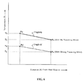
- the temperature T of the outside (outer wall region) of the engine in the cooling fin and its vicinity decreases to Ts (at a point Ps), but the actual engine temperature T of the inside (wall surface of the combustion chamber) of the engine is the temperature T 0 or a little less that is approximately equal to the temperature in steady operations.
- the engine is not controlled in originally preferable operating conditions.
- an object of the present invention to provide an engine control apparatus capable of detecting the temperature of an engine with high accuracy eliminating effects of ambience such as traveling wind and outside-air temperature to control the engine in optimal operating conditions, while using existing parts, simplifying the structure and reducing the cost.
- An engine control apparatus of the present invention has temperature detecting means for detecting the temperature of an engine, and control means for controlling operating conditions of the engine based on at least information detected in the temperature detecting means, where the temperature detecting means includes a first temperature sensor and a second temperature sensor that detect respective temperatures of two spaced portions in a combustion chamber demarcating member that demarcates a combustion chamber of the engine, and the control means includes calculating means that calculates the engine temperature inside the engine based on information detected by the first temperature sensor and the second temperature sensor.
- the first temperature sensor and the second temperature sensor detect respective temperatures of different positions (for example, different positions on a cylinder head or different positions on a cylinder block) of the combustion chamber demarcating member, and based on the detected temperature information, the calculating means estimates the actual engine temperature (effective engine temperature) inside the engine by calculation.
- the engine temperature is estimated based on temperatures detected in at least two positions on the combustion chamber demarcating member (for example, cylinder head or cylinder block), the accuracy is improved, and the optimal engine control is performed.
- the calculating means calculates the engine temperature inside the engine based on a function of a temperature difference obtained from the first temperature sensor and the second temperature sensor and the thermal resistance of the engine.
- the calculating means performs calculation on the function of a temperature difference obtained from two pieces of temperature information and the thermal resistance specific to the engine, using as its inputs the two pieces of temperature information obtained from the first temperature sensor and the second temperature sensor, to estimate the actual engine temperature.
- the first temperature sensor is attached to an outer wall of the combustion chamber demarcating member, and the second temperature sensor is attached to a base region of a cooling fin formed on the outer wall.
- the temperature of the base region of the cooling fin is generally lower than that of the outer wall of the combustion chamber demarcating member (for example, cylinder head or cylinder block), a definite temperature difference is obtained and it is possible to obtain a constant relationship (function) where the temperature decreases in inverse proportion to a distance from a heat source (for example, a wall surface of the combustion chamber).
- a heat source for example, a wall surface of the combustion chamber
- the first temperature sensor and the second temperature sensor are composed of an integrally formed one-piece temperature sensor.
- providing only a single one-piece temperature sensor enables detections of respective temperatures of two portions on the combustion chamber demarcating member (for example, cylinder head or cylinder block), and it is thus possible to simplify handling, mounting and other operations of the sensor.
- the one-piece temperature sensor is attached to the outer wall of the combustion chamber demarcating member or the base region of the cooling fin formed on the outer wall.
- the one-piece temperature sensor readily only by providing a single mounting hole or the like on the combustion chamber demarcating member (for example, cylinder head or cylinder block).
- control means obtains load conditions of the engine based on the information detected by the first temperature sensor and the second temperature sensor to control a fuel injection amount.
- control means obtains the load conditions (operating conditions) of the engine based on the obtained two pieces of temperature information, and using the obtained load conditions and a predetermined control map, controls fuel injection so that a proper fuel amount is injected.
- the optimal fuel injection is thus performed in response to actual load conditions of the engine.
- the engine to be controlled is an air-cooled engine.
- the present invention is particularly effective as a method of estimating the actual engine temperature inside the engine from the temperature in the vicinity of the outer wall of the combustion chamber demarcating member (for example, cylinder head or cylinder block).
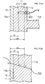
- Figs. 1 to 4 illustrate one embodiment of an engine control apparatus according to the present invention.
- Fig. 1 is a system diagram of the entire apparatus including the engine.
- Fig. 2(a) is a cross-sectional view showing temperature sensors as the temperature detecting means.
- Fig. 2(b) is a heat transmission property in the state.
- Fig. 3 is a graph to explain a temperature detection function.
- Fig. 4 is an equivalent circuit that is an electric circuit as a substitution for heat transmission property of the engine.
- an engine to be controlled is an air-cooled 4 cycle engine 10 mounted on a vehicle such as a two-wheeled vehicle.
- the engine 10 has a cylinder block 11 on which a plurality of cooling fins 11b is formed to project from an outer wall 11a and which is of a combustion chamber demarcating member that demarcates part of a combustion chamber, a cylinder liner 12 that is engaged in a bore of the cylinder block 11, a cylinder head 13 which is coupled to an upper end of the cylinder block 11 and is of the combustion chamber demarcating member that demarcates part of the combustion chamber, a piston 14 that reciprocates inside the cylinder liner 12, an intake pipe 15 that forms an intake passage 15a communicating with an intake port 13a of the cylinder head 13, an injector 16 that is attached to the intake pipe 15, a throttle valve 17 that opens and closes the intake passage 15a, a fuel tank 18 that supplies the fuel to the injector 16, an ignition plug and coil (not shown) and others.
- a control apparatus of the engine 10 has temperature detecting means 20 that detects the temperature of the cylinder block 11, a throttle position sensor 23 that detects an angle of the throttle valve 17, a rotation sensor 24 that detects the number of rotations of a crank shaft, control means 30 that controls operating conditions of the engine 10 based on information detected by the temperature detecting means 20, throttle position sensor 23, rotation sensor 24, etc, and others.
- the temperature detecting means 20 is comprised of a first temperature sensor 21 mounted on the outer wall 11a of the cylinder block 11, and a second temperature sensor 22 mounted on a base region of the cooling fin formed on the outer wall 11a of the cylinder block 11.
- the first temperature sensor 21 and second temperature sensor 22 are each composed of, for example, a thermocouple using thermistor and Seebeck effect, and as shown in Fig. 2(a), are disposed respectively at positions distances X1 and X2 apart from an inner wall surface 12a, on the assumption that the temperature of the inner wall surface 12a of the cylinder liner 12 is equivalent to the wall surface temperature T 0 of the combustion chamber (heat source).
- the heat transmission property indicating the mutual relationship between the detection temperature T 1 of the first temperature sensor 21, detection temperature T 2 of the second temperature sensor 22 and outside-air temperature Tout is represented by a constant relationship expressed by an approximately liner temperature gradient in a region of the cylinder liner 12 and cylinder block 11.
- holes are provided on the outer wall 11a of the cylinder block 11 and the cooling fin 11b to mount the sensors, whereby the sensors are attached or detached readily.
- the control means 30 controls fuel injection amounts, injection timing, ignition timing, etc. as appropriate to control operating conditions of the engine 10, and as shown in Fig. 1, is formed of a first temperature detecting circuit 32 connected to the first temperature sensor 21, a second temperature detecting circuit 33 connected to the second temperature sensor 22, a calculating circuit 34 as calculating means, an injector driving circuit 35 that drives the injector 16, a throttle position detecting circuit 36 connected to the throttle position sensor 23, a number-of-rotation detecting circuit 37 connected to the rotation sensor 24, a storage section 38 that beforehand stores information on control map and others, and so on.
- the first temperature detecting circuit 32 and second temperature detecting circuit 33 convert analog signals output from the first temperature sensor 21 and second temperature sensor 22 into digital signals to output as voltage signals V1 and V2, respectively.
- the calculating circuit 34 Based on the output information (detection information) of the first temperature detecting circuit 32 (first temperature sensor 21) and second temperature detecting circuit 33 (second temperature sensor 22), the calculating circuit 34 performs predetermined calculating processing to calculate the engine temperature T 0 inside the engine.
- the first temperature sensor 21 detects the temperature T 1 (at a point P 1 )
- the second temperature sensor 22 detects the temperature T 2 (at a point P 2 )
- the temperature gradient a is calculated from the temperature difference ⁇ T between the temperatures T 1 and T 2 , and the spacing distance ⁇ X between points of the temperatures.
- the first temperature sensor 21 detects the temperature T 1 ' (at a point P 1 ')
- the second temperature sensor 22 detects the temperature T 2 ' (at a point P 2 ')(herein T 1 ' ⁇ T 1 and T 2 ' ⁇ T 2 )
- temperature differences ⁇ T and ⁇ T' are obtained from temperatures T 1 and T 1 ' detected in the first temperature sensor 21, and T 2 and T 2 ' detected in the second temperature sensor 22, and the heat transmission property (temperature gradients a and a') of the engine 10 is further obtained, whereby it is possible to estimate the actual engine temperature T 0 inside the engine in response to load conditions (operating conditions) of the engine 10 with high accuracy and with ease.
- a heat value inside the engine 10 is represented by Ieng(W)
- the engine temperature is represented by Veng (°C)
- the thermal resistance of the cylinder liner 12 is represented by Rsyl(°C/W)
- the heat capacity of the cylinder liner 12 is represented by Csyl
- the thermal resistance of the cylinder block 11 is represented by Rsyb(°C/W)
- the heat capacity of the cylinder block 11 is represented by Csyb
- the detection temperature of the first temperature sensor 21 (S1) is represented by V1 (°C)
- the detection temperature of the second temperature sensor 22 (S2) is represented by V2 (°C)
- the thermal resistance between the first temperature sensor 21 and second temperature sensor 22 is represented by R12 (°C/W)
- the thermal resistance between the second temperature sensor 22 and outside air is represented by R2a (°C/W)
- the outside-air temperature Tout is represented by Vout R12 (°C
- the calculating circuit 34 obtains a linear function indicating the constant relationship from the temperature difference (V1-V2) obtained from temperatures V1 and V2 continuously detected and thermal resistance R12, Rsyl and Rsyb specific to the engine, and based on the linear function, calculates the actual engine temperature Veng inside the engine. In this way, the calculation is simplified, and it is made possible to perform prompt calculation processing, enabling the prompt control with high accuracy in response to load conditions of the engine 10.
- the detection signals are input to the calculating circuit 34 respectively through the first temperature detecting circuit 32 and second temperature detecting circuit 33, and based on the input signals, the calculating circuit 34 calculates the engine temperature T 0 inside the engine 10 and inputs the calculation result to the control section 31.
- the detection signal is input to the control section 31 through the throttle position detecting circuit 36.
- the rotation sensor 24 detects the number of rotations of the engine 10
- the detection signal is input to the control section 31 through the number-of-rotation detecting circuit 37.
- the control section 31 Based on the information detected by the sensors 21, 22, 23 and 24, the control map stored in the storage section 38 and so on, the control section 31 obtains the load conditions, operating condition and the like of the engine 10, calculates an optimal fuel injection amount (fuel injection time and fuel injection timing) at any given time, and issues a control signal.
- the injector 16 When the control signal is issued, the injector 16 is driven based on a driving signal from the injector driving circuit 35, and a required amount of fuel is injected at required timing. Further, when the control section 31 issues a control signal to the injection coil, the injection plug makes a spark at required timing.
- the engine 10 is controlled to be in optimal operating conditions corresponding to the load conditions.
- the engine temperature T 0 is estimated using the first temperature sensor 21 and second temperature sensor 22, effects are eliminated that are caused by, for example, a driving condition of the vehicle such as a two-wheeled vehicle mounted with the engine 10, the presence or absence of traveling wind and outside-air temperature, and the actual engine temperature T 0 is obtained with high accuracy.
- a driving condition of the vehicle such as a two-wheeled vehicle mounted with the engine 10
- the presence or absence of traveling wind and outside-air temperature the actual engine temperature T 0 is obtained with high accuracy.
- the engine is controlled in optimal operating conditions and the drivability is improved.
- Fig. 5 illustrates another embodiment of the engine control apparatus according to the present invention.
- a single temperature sensor 200 is attached as the temperature detecting means onto the outer wall 11a of the cylinder block 11 as the combustion chamber demarcating member.
- the temperature sensor 200 is a one-piece temperature sensor composed of integrally formed first temperature sensor 210 that detects the temperature at a position X1' apart from the inner wall 12a of the cylinder liner 12 and second temperature sensor 220 that detects the temperature at a position X2' apart from the inner wall 12a.
- temperatures T 1 and T 2 (or T 1 ' and T 2 ') of two portions on the cylinder block 11 are detected, and the actual engine temperature T 0 is calculated.
- the one-piece temperature sensor 200 is attached to the outer wall 11a of the cylinder block 11 herein, the sensor 200 may be attached to the cooling fin lib.
- control apparatus of the present invention is applied to the air-cooled engine 10 mounted on a vehicle such as a two-wheeled vehicle.
- present invention is not limited to the case, and the apparatus is applicable to air-cooled engines mounted on leisure vehicles, work vehicles, other vehicles, work machines or the like.
- control apparatus of the present invention is similarly applicable to water-cooled engines as long as a definite temperature difference is obtained in detecting temperatures of two portions on the combustion chamber demarcating member (on the cylinder block or cylinder head).
- the present invention is not limited to the case.
- the means may be attached onto the cylinder head 13 as the combustion chamber demarcating member where cooling fins are formed to project from the outer wall.
- two temperature sensors that detect respective temperatures of two portions on the combustion chamber demarcating member are adopted as the temperature detecting means for detecting the temperature of the engine, and based on the information detected by the two temperature sensors, the actual engine temperature inside the engine is estimated, whereby the accuracy is improved and the optimal engine control is performed.
- the engine temperature inside the engine is calculated based on the function of a temperature difference obtained from the two temperature sensors and thermal resistance specific to the engine, whereby the calculation processing is simplified and made fast, and it is possible to perform prompt and optimal control in response to load conditions of the engine.
- load conditions of the engine are obtained based on the information detected by the two temperature sensors to control a fuel injection amount, optimal fuel injection is performed in response to the actual load conditions of the engine and the drivability of the vehicle such as a two-wheeled vehicle is improved.
Landscapes
- Engineering & Computer Science (AREA)
- Chemical & Material Sciences (AREA)
- Combustion & Propulsion (AREA)
- Mechanical Engineering (AREA)
- General Engineering & Computer Science (AREA)
- Electrical Control Of Air Or Fuel Supplied To Internal-Combustion Engine (AREA)
- Combined Controls Of Internal Combustion Engines (AREA)
Abstract
Description
- Fig. 1
- is a system diagram illustrating one embodiment of an engine control apparatus according to the present invention;
- Fig. 2(a)
- is a cross-sectional view illustrating a state of a mounted first temperature sensor and second temperature sensor that are temperature detecting means composing part of the engine control apparatus;
- Fig. 2(b)
- is a heat transmission property in the state;
- Fig. 3
- is a graph to explain a detection method by the temperature detecting means;
- Fig. 4
- is an equivalent circuit that is an electric circuit as a substitution for heat transmission paths of the engine;
- Fig. 5(a)
- is a cross-sectional view illustrating a state of a mounted one-piece temperature sensor in another embodiment of the engine control apparatus according to the present invention;
- Fig. 5(b)
- is a view illustrating a heat transmission property in the state; and
- Fig. 6
- is a graph illustrating a detection method by a conventional temperature sensor.
Claims (7)
- An engine control apparatus comprising:wherein the temperature detecting means includes a first temperature sensor and a second temperature sensor that detect respective temperatures of two spaced portions in a combustion chamber demarcating member that demarcates a combustion chamber of the engine, and the control means includes calculating means that calculates an engine temperature inside the engine based on information detected by the first temperature sensor and the second temperature sensor.temperature detecting means for detecting a temperature of an engine; andcontrol means for controlling operating conditions of the engine based on at least information detected in the temperature detecting means,
- The engine control apparatus according to claim 1, wherein the calculating means calculates the engine temperature inside the engine based on a function of a temperature difference obtained from the first temperature sensor and the second temperature sensor and thermal resistance of the engine.
- The engine control apparatus according to claim 1 or 2, wherein the first temperature sensor is attached to an outer wall of the combustion chamber demarcating member, and the second temperature sensor is attached to a base region of a cooling fin formed on the outer wall.
- The engine control apparatus according to any one of claims 1 to 3, wherein the first temperature sensor and the second temperature sensor are composed of an integrally formed one-piece temperature sensor.
- The engine control apparatus according to claim 4, wherein the one-piece temperature sensor is attached to the outer wall of the combustion chamber demarcating member or the base region of the cooling fin formed on the outer wall.
- The engine control apparatus according to any one of claims 1 to 5, wherein the control means obtains load conditions of the engine based on the information detected by the first temperature sensor and the second temperature sensor to control a fuel injection amount.
- The engine control apparatus according to any one of claims 1 to 6, wherein the engine is an air-cooled engine.
Applications Claiming Priority (2)
| Application Number | Priority Date | Filing Date | Title |
|---|---|---|---|
| JP2002163881A JP2004011483A (en) | 2002-06-05 | 2002-06-05 | Engine control device |
| JP2002163881 | 2002-06-05 |
Publications (2)
| Publication Number | Publication Date |
|---|---|
| EP1369572A2 true EP1369572A2 (en) | 2003-12-10 |
| EP1369572A3 EP1369572A3 (en) | 2006-05-03 |
Family
ID=29545764
Family Applications (1)
| Application Number | Title | Priority Date | Filing Date |
|---|---|---|---|
| EP03011170A Withdrawn EP1369572A3 (en) | 2002-06-05 | 2003-05-27 | Engine control apparatus |
Country Status (3)
| Country | Link |
|---|---|
| EP (1) | EP1369572A3 (en) |
| JP (1) | JP2004011483A (en) |
| CN (1) | CN1329649C (en) |
Cited By (5)
| Publication number | Priority date | Publication date | Assignee | Title |
|---|---|---|---|---|
| EP1564395A3 (en) * | 2004-02-17 | 2007-02-28 | Toyota Jidosha Kabushiki Kaisha | Fuel injection control apparatus and fuel injection control method for diesel engine |
| US20130054121A1 (en) * | 2011-08-24 | 2013-02-28 | Walbro Engine Management, L.L.C. | Fuel injected engine system |
| FR2996168A1 (en) * | 2012-10-02 | 2014-04-04 | Peugeot Citroen Automobiles Sa | Calculation device for calculating substitution temperature of cooling water for driving thermal engine of car, has calibration unit for calculating barycenter between measured and oil temperatures to obtain substitution temperature |
| US10947918B1 (en) | 2020-05-21 | 2021-03-16 | Honda Motor Co., Ltd. | Apparatus for controlling an engine during a shift event, powertrain including same, and method |
| US11280291B2 (en) | 2019-12-31 | 2022-03-22 | Mahle International Gmbh | Cylinder liner with temperature sensor |
Families Citing this family (6)
| Publication number | Priority date | Publication date | Assignee | Title |
|---|---|---|---|---|
| BRPI0405357B1 (en) * | 2004-11-26 | 2019-04-02 | Magneti Marelli Sistemas Automotivos Indústria E Comércio Ltda. | FUEL TETRA ENGINE CONTROL SYSTEM |
| JP4940099B2 (en) * | 2007-10-23 | 2012-05-30 | 本田技研工業株式会社 | Fluid temperature estimation device for internal combustion engine |
| US8352158B2 (en) * | 2011-11-21 | 2013-01-08 | Ford Global Technologies, Llc | Method and system for compensating engine thermal conditions |
| CN105020037A (en) * | 2014-04-29 | 2015-11-04 | 长城汽车股份有限公司 | Method and system for controlling temperature in cylinders in dual-fuel engine and vehicle |
| US10087863B2 (en) | 2014-12-24 | 2018-10-02 | Keihin Corporation | Internal combustion engine control device |
| JP6251766B2 (en) * | 2016-03-24 | 2017-12-20 | 株式会社ケーヒン | Internal combustion engine control device |
Citations (1)
| Publication number | Priority date | Publication date | Assignee | Title |
|---|---|---|---|---|
| JPH0734927A (en) | 1993-07-19 | 1995-02-03 | Toyota Motor Corp | Air-fuel ratio controller for internal combustion engine |
Family Cites Families (3)
| Publication number | Priority date | Publication date | Assignee | Title |
|---|---|---|---|---|
| JPS59103235U (en) * | 1982-12-27 | 1984-07-11 | 本田技研工業株式会社 | Temperature measurement device for internal combustion engines |
| JPH041436A (en) * | 1990-04-17 | 1992-01-06 | Mazda Motor Corp | Fuel control device for engine |
| JPH0552670A (en) * | 1991-08-29 | 1993-03-02 | Japan Electron Control Syst Co Ltd | Combustion temperature sensor |
-
2002
- 2002-06-05 JP JP2002163881A patent/JP2004011483A/en active Pending
-
2003
- 2003-05-27 EP EP03011170A patent/EP1369572A3/en not_active Withdrawn
- 2003-06-03 CN CNB031372341A patent/CN1329649C/en not_active Expired - Fee Related
Patent Citations (1)
| Publication number | Priority date | Publication date | Assignee | Title |
|---|---|---|---|---|
| JPH0734927A (en) | 1993-07-19 | 1995-02-03 | Toyota Motor Corp | Air-fuel ratio controller for internal combustion engine |
Cited By (8)
| Publication number | Priority date | Publication date | Assignee | Title |
|---|---|---|---|---|
| EP1564395A3 (en) * | 2004-02-17 | 2007-02-28 | Toyota Jidosha Kabushiki Kaisha | Fuel injection control apparatus and fuel injection control method for diesel engine |
| US20130054121A1 (en) * | 2011-08-24 | 2013-02-28 | Walbro Engine Management, L.L.C. | Fuel injected engine system |
| US9371786B2 (en) * | 2011-08-24 | 2016-06-21 | Walbro Llc | Fuel injected engine system |
| US9765724B2 (en) | 2011-08-24 | 2017-09-19 | Walbro Llc | Fuel injected engine system |
| FR2996168A1 (en) * | 2012-10-02 | 2014-04-04 | Peugeot Citroen Automobiles Sa | Calculation device for calculating substitution temperature of cooling water for driving thermal engine of car, has calibration unit for calculating barycenter between measured and oil temperatures to obtain substitution temperature |
| RU2628466C2 (en) * | 2012-10-02 | 2017-08-17 | Пежо Ситроен Отомобиль Са | Substitutive coolant temperature calculation device of internal combustion engine, equipped with additional heater |
| US11280291B2 (en) | 2019-12-31 | 2022-03-22 | Mahle International Gmbh | Cylinder liner with temperature sensor |
| US10947918B1 (en) | 2020-05-21 | 2021-03-16 | Honda Motor Co., Ltd. | Apparatus for controlling an engine during a shift event, powertrain including same, and method |
Also Published As
| Publication number | Publication date |
|---|---|
| JP2004011483A (en) | 2004-01-15 |
| CN1467367A (en) | 2004-01-14 |
| EP1369572A3 (en) | 2006-05-03 |
| CN1329649C (en) | 2007-08-01 |
Similar Documents
| Publication | Publication Date | Title |
|---|---|---|
| JP3538545B2 (en) | Radiator failure detection device for internal combustion engine | |
| US7677086B2 (en) | Engine oil viscosity diagnostic systems and methods | |
| US5606855A (en) | Apparatus and method for estimating the temperature of an automotive catalytic converter | |
| EP1369572A2 (en) | Engine control apparatus | |
| KR20120036333A (en) | Control apparatus for internal combustion engine | |
| JP2009257198A (en) | Diagnosis apparatus for internal combustion engine | |
| JP4055545B2 (en) | Oil dilution fuel estimation device and control device for internal combustion engine using the same | |
| JP2014156849A (en) | Control device of internal combustion engine | |
| JP4296810B2 (en) | Lubricant viscosity measurement in internal combustion engines. | |
| JP3636047B2 (en) | Power control device for sensor temperature rise | |
| US7836862B2 (en) | Systems and methods for predicting engine delta friction torque using both coolant and oil temperature | |
| US10787953B2 (en) | Device for determining abnormalities of cooling water temperature sensors | |
| CN108506108A (en) | Electronic-circuit device and the vehicle for using electronic-circuit device | |
| JP2010025024A (en) | Abnormality detector of temperature sensor | |
| JP2021017862A (en) | Lubrication oil deterioration determination device | |
| CN118871659A (en) | Vehicle-mounted control device and internal combustion engine control method | |
| JP2005330847A (en) | In-cylinder pressure sensor failure diagnosis device | |
| US10378422B2 (en) | Thermostat abnormality determining device | |
| JP4393533B2 (en) | Fuel injection control device for internal combustion engine | |
| JP5358312B2 (en) | Cooling system | |
| JPH09268936A (en) | Air-cooled multi-cylinder internal combustion engine | |
| KR100410500B1 (en) | Thermostat fail detecting method in a vehicle | |
| US7185624B1 (en) | Fuel injection control apparatus of engine | |
| JP7363727B2 (en) | Internal combustion engine control devices and internal combustion engine systems | |
| JP2011185230A (en) | Abnormality determining device of water temperature sensor |
Legal Events
| Date | Code | Title | Description |
|---|---|---|---|
| PUAI | Public reference made under article 153(3) epc to a published international application that has entered the european phase |
Free format text: ORIGINAL CODE: 0009012 |
|
| AK | Designated contracting states |
Kind code of ref document: A2 Designated state(s): AT BE BG CH CY CZ DE DK EE ES FI FR GB GR HU IE IT LI LU MC NL PT RO SE SI SK TR |
|
| AX | Request for extension of the european patent |
Extension state: AL LT LV MK |
|
| PUAL | Search report despatched |
Free format text: ORIGINAL CODE: 0009013 |
|
| AK | Designated contracting states |
Kind code of ref document: A3 Designated state(s): AT BE BG CH CY CZ DE DK EE ES FI FR GB GR HU IE IT LI LU MC NL PT RO SE SI SK TR |
|
| AX | Request for extension of the european patent |
Extension state: AL LT LV MK |
|
| 17P | Request for examination filed |
Effective date: 20060602 |
|
| 17Q | First examination report despatched |
Effective date: 20060706 |
|
| AKX | Designation fees paid |
Designated state(s): GB IT |
|
| REG | Reference to a national code |
Ref country code: DE Ref legal event code: 8566 |
|
| STAA | Information on the status of an ep patent application or granted ep patent |
Free format text: STATUS: THE APPLICATION IS DEEMED TO BE WITHDRAWN |
|
| 18D | Application deemed to be withdrawn |
Effective date: 20091201 |