EP1369561A2 - Direct fuel injection internal combustion engine - Google Patents
Direct fuel injection internal combustion engine Download PDFInfo
- Publication number
- EP1369561A2 EP1369561A2 EP03011365A EP03011365A EP1369561A2 EP 1369561 A2 EP1369561 A2 EP 1369561A2 EP 03011365 A EP03011365 A EP 03011365A EP 03011365 A EP03011365 A EP 03011365A EP 1369561 A2 EP1369561 A2 EP 1369561A2
- Authority
- EP
- European Patent Office
- Prior art keywords
- fuel injection
- fuel
- wall surface
- piston
- internal combustion
- Prior art date
- Legal status (The legal status is an assumption and is not a legal conclusion. Google has not performed a legal analysis and makes no representation as to the accuracy of the status listed.)
- Withdrawn
Links
- 239000000446 fuel Substances 0.000 title claims abstract description 421
- 238000002347 injection Methods 0.000 title claims abstract description 294
- 239000007924 injection Substances 0.000 title claims abstract description 294
- 238000002485 combustion reaction Methods 0.000 title claims abstract description 119
- 239000000203 mixture Substances 0.000 claims abstract description 72
- 230000006835 compression Effects 0.000 claims description 27
- 238000007906 compression Methods 0.000 claims description 27
- 230000002093 peripheral effect Effects 0.000 claims description 12
- 238000013459 approach Methods 0.000 claims description 8
- 230000007423 decrease Effects 0.000 claims description 4
- 238000005054 agglomeration Methods 0.000 description 29
- 230000002776 aggregation Effects 0.000 description 29
- 229930195733 hydrocarbon Natural products 0.000 description 12
- 150000002430 hydrocarbons Chemical class 0.000 description 12
- 239000000779 smoke Substances 0.000 description 9
- 230000006870 function Effects 0.000 description 7
- 230000002829 reductive effect Effects 0.000 description 6
- 230000008859 change Effects 0.000 description 5
- 230000002349 favourable effect Effects 0.000 description 5
- 230000015572 biosynthetic process Effects 0.000 description 2
- 238000009826 distribution Methods 0.000 description 2
- 235000012489 doughnuts Nutrition 0.000 description 2
- 230000000670 limiting effect Effects 0.000 description 2
- 230000036961 partial effect Effects 0.000 description 2
- 230000000149 penetrating effect Effects 0.000 description 2
- 230000035515 penetration Effects 0.000 description 2
- 239000004215 Carbon black (E152) Substances 0.000 description 1
- 238000010276 construction Methods 0.000 description 1
- 238000001816 cooling Methods 0.000 description 1
- 238000005520 cutting process Methods 0.000 description 1
- 230000003247 decreasing effect Effects 0.000 description 1
- 238000010586 diagram Methods 0.000 description 1
- 230000006872 improvement Effects 0.000 description 1
- 230000002452 interceptive effect Effects 0.000 description 1
- 238000004519 manufacturing process Methods 0.000 description 1
- 238000000034 method Methods 0.000 description 1
- 230000004048 modification Effects 0.000 description 1
- 238000012986 modification Methods 0.000 description 1
- 230000008569 process Effects 0.000 description 1
- 230000004044 response Effects 0.000 description 1
- 230000000630 rising effect Effects 0.000 description 1
- 238000003860 storage Methods 0.000 description 1
Images


Classifications
-
- F—MECHANICAL ENGINEERING; LIGHTING; HEATING; WEAPONS; BLASTING
- F02—COMBUSTION ENGINES; HOT-GAS OR COMBUSTION-PRODUCT ENGINE PLANTS
- F02B—INTERNAL-COMBUSTION PISTON ENGINES; COMBUSTION ENGINES IN GENERAL
- F02B23/00—Other engines characterised by special shape or construction of combustion chambers to improve operation
- F02B23/08—Other engines characterised by special shape or construction of combustion chambers to improve operation with positive ignition
- F02B23/10—Other engines characterised by special shape or construction of combustion chambers to improve operation with positive ignition with separate admission of air and fuel into cylinder
- F02B2023/103—Other engines characterised by special shape or construction of combustion chambers to improve operation with positive ignition with separate admission of air and fuel into cylinder the injector having a multi-hole nozzle for generating multiple sprays
-
- F—MECHANICAL ENGINEERING; LIGHTING; HEATING; WEAPONS; BLASTING
- F02—COMBUSTION ENGINES; HOT-GAS OR COMBUSTION-PRODUCT ENGINE PLANTS
- F02B—INTERNAL-COMBUSTION PISTON ENGINES; COMBUSTION ENGINES IN GENERAL
- F02B75/00—Other engines
- F02B75/12—Other methods of operation
- F02B2075/125—Direct injection in the combustion chamber for spark ignition engines, i.e. not in pre-combustion chamber
-
- F—MECHANICAL ENGINEERING; LIGHTING; HEATING; WEAPONS; BLASTING
- F02—COMBUSTION ENGINES; HOT-GAS OR COMBUSTION-PRODUCT ENGINE PLANTS
- F02B—INTERNAL-COMBUSTION PISTON ENGINES; COMBUSTION ENGINES IN GENERAL
- F02B2275/00—Other engines, components or details, not provided for in other groups of this subclass
- F02B2275/18—DOHC [Double overhead camshaft]
-
- Y—GENERAL TAGGING OF NEW TECHNOLOGICAL DEVELOPMENTS; GENERAL TAGGING OF CROSS-SECTIONAL TECHNOLOGIES SPANNING OVER SEVERAL SECTIONS OF THE IPC; TECHNICAL SUBJECTS COVERED BY FORMER USPC CROSS-REFERENCE ART COLLECTIONS [XRACs] AND DIGESTS
- Y02—TECHNOLOGIES OR APPLICATIONS FOR MITIGATION OR ADAPTATION AGAINST CLIMATE CHANGE
- Y02T—CLIMATE CHANGE MITIGATION TECHNOLOGIES RELATED TO TRANSPORTATION
- Y02T10/00—Road transport of goods or passengers
- Y02T10/10—Internal combustion engine [ICE] based vehicles
- Y02T10/12—Improving ICE efficiencies
Definitions
- the present invention generally relates to a direct fuel injection internal combustion engine that employs a center injection arrangement in which a fuel injection valve and a spark plug are arranged on or near a reciprocation axis of the piston. More specifically, the present invention relates to an improvement to the shapes of cavities located in a top surface of the piston and to the control of frequency and timing of the fuel injection.
- the fuel-air mixture agglomeration may be formed in the shape of a donut and cause the stability of the spark plug ignition to be reduced.
- the upward-swirling fuel stream can be made to gather in the center of the combustion chamber by slanting the lateral wall surfaces inward (into a reentrant shape).
- the more the lateral wall surfaces are slanted the poorer the S/V ratio of the combustion chamber becomes and the more the output and fuel efficiency performance are degraded.
- the act of gathering the upper part of the fuel-air mixture in the center of the combustion chamber is contrary to the original objective of obtaining a low stratified charge state.
- Figure 2(a) is a top plan view of a piston adapted to the direct fuel injection internal combustion engine illustrated in Figure 1 in accordance with the first embodiment of the present invention
- Figure 2(b) is a partial cross sectional view of the piston illustrated in Figure 2(a) taken along a section line 2(b)-2(b) in Figure 2(a) in accordance with the first embodiment of the present invention
- Figure 4(a) is a schematic view of an fuel injection valve adapted to the direct fuel injection internal combustion engine illustrated in Figure 1 that utilizes a multi hole nozzle to form a hollow cone of fuel from a plurality of fuel streams in accordance with the first embodiment of the present invention
- Figure 5(c) is a schematic view of the fuel pattern created by the fuel stream from the fuel injection valve illustrated in Figure 5(a) and 5(b) at the point where the fuel stream hits the top surface of the piston;
- Figure 6(a)-(c) are sequential schematic views of the direct fuel injection internal combustion engine illustrated in Figure 1 that show a shape of the piston and a fuel stream behavior during stratified high-load operating conditions in accordance with the first embodiment of the present invention
- Figure 8 is a diagram that illustrates how the fuel injection timing and fuel injection quantity are controlled with respect to the engine load in accordance with the first embodiment of the present invention
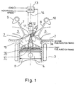
- the direct fuel injection internal combustion engine in accordance with the first embodiment of the present invention includes a combustion chamber 1, a fuel injection valve 11, a spark plug 12 and a piston 4 with an outer cavity 16 and an inner cavity 17.
- the outer cavity 16 and the inner cavity 17 are arranged to be substantially rotationally symmetrical (axially symmetrical or toroidal) with respect to a reciprocation axis 14 of the piston 4.
- the phrase "substantially axially symmetrical” should be interpreted to include minor variations in the surface that do not alter the objectives of the present invention.
- the phrase "substantially axially symmetrical” includes a slightly flattened circle, or shapes in which a portion of the surface has been removed.
- a stratified charge combustion is conducted in the direct fuel injection internal combustion engine of the present invention, either the outer cavity 16 or the inner cavity 17 is used appropriately to form a fuel-air mixture in the vicinity of the spark plug 12 depending on an engine operating condition.
- good fuel efficiency can be obtained and the exhaust of unburned hydrocarbons can be sufficiently suppressed.
- a relatively large stratified fuel-air mixture agglomeration can be obtained when the engine operating conditions are within a prescribed operating region.
- the occurrence of a lean fuel-air mixture region in the center of the fuel-air mixture agglomeration i.e., a donut-shaped fuel-air mixture agglomeration
- the combustion chamber 1 is basically defined by a cylinder head 2, a cylinder block 3 and the piston 4.
- the fuel injection valve 11 and the spark plug 12 are mounted in the cylinder head 2.
- the piston 4 has a top surface 15 that includes the outer cavity 16 and the inner cavity 17.
- the piston 4 has piston rings that slideably engage an internal surface 3a of the cylinder block 3.
- the cylinder head 2 includes at lease one intake port 5 and at least one exhaust port 6 that open into the combustion chamber 1.
- the intake port 5 and the exhaust port 6 are opened and closed by an intake valve 7 and an exhaust valve 8, which are driven using an intake cam 9 and an exhaust cam 10, respectively.
- the fuel injection valve 11 injects fuel directly into the combustion chamber 1 toward the top surface 15 of the piston 4.
- the spark plug 12 ignites a fuel-air mixture inside the combustion chamber 1.
- a reciprocation axis of the piston can be any axis taken at one point on the piston that is parallel to a direction of the reciprocation movement of the piston.
- the reciprocation axis 14 of the piston 4 and the center axis of the cylinder can be apart from each other as long as the fuel injection valve 11 and the spark plug 12 are arranged to lie on or near the reciprocation axis 14 of the piston 4.
- the internal RAM of the engine control unit 13 stores statuses of operational flags and various control data. It will be apparent to those skilled in the art from this disclosure that the precise structure and algorithms for the engine control unit 13 can be any combination of hardware and software that will carry out the functions of the present invention. In other words, "means plus function" clauses as utilized in the specification and claims should include any structure or hardware and/or algorithm or software that can be utilized to carry out the function of the "means plus function” clause.
- the engine control unit 13 is a conventional component that is well known in the art. Since engine control units are well known in the art, the particulars of the engine control unit 13 will not be discussed or illustrated in detail herein.
- the outer curved section 16e of the second outer wall surface 16b gradually upwardly inclines as it extends in a radial outward direction such that the fuel stream injected against the first outer wall surface 16a is directed toward the third outer wall surface 16c along the second outer wall surface 16b without any abrupt changes in direction.
- the third outer wall surface 16c extends directly from the second outer wall surface 16b and forms an outer peripheral wall of the entire the outer cavity 16.
- the third outer wall surface 16c extends in an upward direction that is substantially parallel to the reciprocation axis 14 of the piston 4.
- substantially parallel should be construed as including a range of the gradients of ⁇ 5° from the parallel.
- the inner cavity 17 is formed as though by cutting away a center portion of the first outer wall surface 16a.
- an annular surface that defines the inner cavity 17 can be basically divided into a first inner wall surface 17a, a second inner wall surface 17b and a third inner wall surface 17c.
- the first inner wall surface 17a is arranged relative to an injection angle of the fuel injection valve 11 such that the fuel stream injected from the fuel injection valve 11 strikes the first inner wall surface 17a at a non-perpendicular angle. More specifically, the first outer wall surface 17a preferably slants upwardly such that it becomes higher as it approaches the reciprocation axis 14 of the piston 4 at the center and, as a whole, forms an conical shape that extends upward.
- the inner curved section of the second inner wall surface 17b gradually upwardly inclines as it extends in a radial outward direction such that the fuel stream injected against the first inner wall surface 17a is directed toward the third inner wall surface 17c along the second inner wall surface 17b without any abrupt changes in direction.
- the radius of curvature Ri of the second inner wall surface 17b is preferably arranged to be smaller than the radius of curvature Rh of the second outer wall surface 16b.
- the third inner wall surface 17c extends in a direction that is substantially parallel to the reciprocation axis 14 of the piston 4.
- substantially parallel should be construed as including a range of the gradients of ⁇ 5° from the parallel.
- the third inner wall surface 17c preferably has an inner reentrant section that approaches the reciprocation axis 14 of the piston 4 as the third inner wall surface 17c extends in an upward and radial inward direction toward the fuel injection valve 11 from the second inner wall surface 17b as seen in Figure 3.
- the inner reentrant section has a reentrant angle e with respect to the reciprocation axis 14 of the piston 4.
- both the third outer wall surface 16c of the outer cavity 16 and the third inner wall surface 17c of the inner cavity 17 have reentrant shapes that become closer to the reciprocation axis 14 of the piston 4 as they extend in the upward direction of the piston 4. Therefore, the fuel-air mixture can be confined inside the outer cavity 16 or the inner cavity 17 effectively after it hits the outer cavity 16 or the inner cavity 17, respectively. Accordingly, the stratified charge combustion can be achieved with good fuel efficiency and few unburned hydrocarbons.
- the reentrant angle e of the inner cavity 17 is preferably arranged to be larger than the reentrant angle d of the outer cavity 16. As a result, fuel spillage from the inner cavity 17 can be sufficiently prevented. Also, stable stratified charge combustion can be accomplished even during idling and other operating regions where the load is extremely low.
- a multi-hole type injection valve with a multi-hole type injection nozzle is preferably used as the fuel injection valve 11 as shown in Figure 4(a).
- the multi-hole type injection valve has strong directionality or penetration such that there will be little change in the shape of the fuel stream even when the cylinder pressure is rising during the latter half of the compression stroke.
- the fuel injection angle does not change depending on the injection back pressure, and thus, the direction in which the fuel stream flows after being injected can be set accurately.
- a highly homogeneous stratified fuel-air mixture agglomeration can be formed by fuel streams that passed through the outer cavity 16 or the inner cavity 17.
- the fuel injection valve 11 can also be replaced with a fuel injection valve 11' with a swirl nozzle that injects a swirling fuel stream.
- the swirl nozzle injection valve is usually structured so as to have a step on the injection vent portion of the nozzle so that a fuel stream shaped like that shown in Figure 5(b) can be achieved.
- the fuel stream injected from the swirl nozzle injection valve is also shaped substantially a hollow circular cone in which a portion of the hollow circular cone is discontinuous in a fuel injection direction, as seen in Figures 5(b) and 5(c).
- an excellent stratified charge combustion that releases few NOx emissions can be achieved. Furthermore, when the outer cavity 16, which has a larger volume than the inner cavity 17, is used to form the stratified fuel-air mixture agglomeration, stable stratified combustion can be achieved when the fuel injection timing is retarded or when the engine operating condition is in high load operating regions where the load is relatively large.
- the outer cavity 16 and the inner cavity 17 can be utilized in accordance with the load even if the injection directions F2 and F4 are the same for both the low load operating region and the high load operating region because the fuel stream will strike the first outer wall surface 16a when the engine is operating in the high load region and the first inner wall surface 17a when the engine is operating in the low load region.
Landscapes
- Engineering & Computer Science (AREA)
- Chemical & Material Sciences (AREA)
- Combustion & Propulsion (AREA)
- Mechanical Engineering (AREA)
- General Engineering & Computer Science (AREA)
- Combustion Methods Of Internal-Combustion Engines (AREA)
Abstract
Description
- The present invention generally relates to a direct fuel injection internal combustion engine that employs a center injection arrangement in which a fuel injection valve and a spark plug are arranged on or near a reciprocation axis of the piston. More specifically, the present invention relates to an improvement to the shapes of cavities located in a top surface of the piston and to the control of frequency and timing of the fuel injection.
- An example of a direct fuel injection internal combustion engine that employs a center injection arrangement in which a fuel injection valve and spark plug are arranged on or near the reciprocation axis of the piston is disclosed in Japanese Laid-Open Patent Publication No. 2000-265841. In this publication, the top surface of the piston is provided with a deep dish part (an inner cavity) that is substantially axially symmetrical with respect to the reciprocation axis of the piston and a plurality of shallow dish parts (outer cavities) that are arranged discontinuously around the perimeter of the deep dish part. The shallow dish parts constitute a valve recess shape to avoid interfering with intake and exhaust valves and are not axially symmetrical with respect to the reciprocation axis of the piston. In this publication, the shape of a fuel stream injected from an injector is that of a hollow cone. When operating in a region of low to medium speed, the fuel injection timing is controlled to occur during a latter half of the compression stroke such that the fuel stream hits the deep dish part. When the fuel stream hits the deep dish part, a high stratified state is obtained in which an agglomerate fuel-air mixture forms inside the deep dish part and thereabove. When operating in a region of high speed, the fuel injection timing is controlled to occur during a former half of the compression stroke such that the fuel stream hits the shallow dish parts. When the fuel stream hits the shallow dish parts, the fuel stream is guided by lateral wall surfaces of the shallow dish parts such that it swirls upward. As a result, a low stratified state is obtained in which a fuel-air mixture agglomeration is formed inside the shallow dish parts and thereabove.
- In view of the above, it will be apparent to those skilled in the art from this disclosure that there exists a need for an improved direct fuel injection internal combustion engine. This invention addresses this need in the art as well as other needs, which will become apparent to those skilled in the art from this disclosure.
- It has been discovered that, in the direct fuel injection internal combustion engine of the prior art explained above, the fuel stream injected into the shallow dish parts spills into the spaces between the shallow dish parts. This spillage of the fuel stream creates the risk of degraded fuel efficiency and increased unburned hydrocarbons when the shallow dish parts are used to conduct stratified charge combustion. On the other hand, when the deep dish part is used to conduct stratified charge combustion, the fuel stream injected at the deep dish part easily spills into the shallow dish parts because the side wall of the deep dish part joins with the shallow dish parts in gradual slopes. Thus, when the deep dish part is used to conduct the stratified charge combustion, degraded fuel efficiency and increased unburned hydrocarbons are also a concern. Moreover, depending on the diameter of the shallow dish parts and the shape of the lateral wall surfaces of the shallow dish parts, the fuel-air mixture agglomeration may be formed in the shape of a donut and cause the stability of the spark plug ignition to be reduced. The upward-swirling fuel stream can be made to gather in the center of the combustion chamber by slanting the lateral wall surfaces inward (into a reentrant shape). However, the more the lateral wall surfaces are slanted, the poorer the S/V ratio of the combustion chamber becomes and the more the output and fuel efficiency performance are degraded. Furthermore, the act of gathering the upper part of the fuel-air mixture in the center of the combustion chamber is contrary to the original objective of obtaining a low stratified charge state.
- The forgoing object of the present invention can basically be attained by providing a direct fuel injection internal combustion engine comprising a combustion chamber, a fuel injection valve and a spark plug. The combustion chamber has a piston movably mounted therein along a reciprocation axis. The fuel injection valve is arranged adjacent the reciprocation axis of the piston to inject a fuel stream directly into the combustion chamber. The spark plug is arranged adjacent the reciprocation axis of the piston to ignite a fuel-air mixture inside the combustion chamber. The piston includes an outer cavity located in a top surface of the piston and being substantially axially symmetrical about the reciprocation axis of the piston. The piston also includes an inner cavity located in the outer cavity and being substantially axially symmetrical about the reciprocation axis of the piston.
- These and other objects, features, aspects and advantages of the present invention will become apparent to those skilled in the art from the following detailed description, which, taken in conjunction with the annexed drawings, discloses a preferred embodiment of the present invention.
- Referring now to the attached drawings which form a part of this original disclosure:
- Figure 1 is a diagrammatic view of a direct fuel injection internal combustion engine in accordance with a first embodiment of the present invention;
- Figure 2(a) is a top plan view of a piston adapted to the direct fuel injection internal combustion engine illustrated in Figure 1 in accordance with the first embodiment of the present invention;
- Figure 2(b) is a partial cross sectional view of the piston illustrated in Figure 2(a) taken along a section line 2(b)-2(b) in Figure 2(a) in accordance with the first embodiment of the present invention;
- Figure 2(c) is a partial cross sectional view of the piston illustrated in Figure 2(a) taken along a section line 2(c)-2(c) in Figure 2(a) in accordance with the first embodiment of the present invention;
- Figure 3 is a simplified schematic view, similar to Figure 2(b), of the piston illustrated in Figure 2(a) showing the shape and various dimensions of the piston in accordance with the first embodiment of the present invention;
- Figure 4(a) is a schematic view of an fuel injection valve adapted to the direct fuel injection internal combustion engine illustrated in Figure 1 that utilizes a multi hole nozzle to form a hollow cone of fuel from a plurality of fuel streams in accordance with the first embodiment of the present invention;
- Figure 4(b) is a schematic view of the fuel pattern created by the fuel streams from the fuel injection valve illustrated in Figure 4(b) at the point where the fuel streams hit the top surface of the piston in according with the first embodiment of the present invention;
- Figure 5(a) is a schematic cross sectional view of an fuel injection valve having a swirl nozzle that is adapted to be used with the direct fuel injection internal combustion engine illustrated in Figure 1 in accordance with the first embodiment of the present invention;
- Figure 5(b) is a schematic side elevational view of the fuel pattern created by the fuel injection valve illustrated in Figure 5(a) and adapted to be used in the direct fuel injection internal combustion engine illustrated in Figure 1 in accordance with the first embodiment of the present invention;
- Figure 5(c) is a schematic view of the fuel pattern created by the fuel stream from the fuel injection valve illustrated in Figure 5(a) and 5(b) at the point where the fuel stream hits the top surface of the piston;
- Figure 6(a)-(c) are sequential schematic views of the direct fuel injection internal combustion engine illustrated in Figure 1 that show a shape of the piston and a fuel stream behavior during stratified high-load operating conditions in accordance with the first embodiment of the present invention;
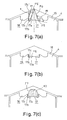
- Figure 7(a)-(c) are sequential schematic views of the direct fuel injection internal combustion engine illustrated in Figure 1 that show the shape of the piston and the fuel stream behavior during stratified low-load operating conditions in accordance with the first embodiment of the present invention;
- Figure 8 is a diagram that illustrates how the fuel injection timing and fuel injection quantity are controlled with respect to the engine load in accordance with the first embodiment of the present invention;
- Figure 9(a)-(c) are sequential schematic views that show the fuel behavior when only a single fuel injection is executed per cycle during stratified low-load operating conditions;
- Figure 10(a)-(d) are sequential schematic views that show the fuel behavior when a pair of fuel injections are executed per cycle during stratified charge high-load operating conditions;
- Figure 11 is a simplified schematic view, similar to Figure 2(b), of a piston adapted to be used in a direct fuel injection internal combustion engine in accordance with a second embodiment of the present invention showing the shape and various dimensions of the piston; and
- Figure 12 illustrates several simplified schematic views of pistons with alternative cavity shapes that can be adapted to a direct fuel injection internal combustion engine in accordance with the present invention.
- Selected embodiments of the present invention will now be explained with reference to the drawings. It will be apparent to those skilled in the art from this disclosure that the following descriptions of the embodiments of the present invention are provided for illustration only and not for the purpose of limiting the invention as defined by the appended claims and their equivalents.
- Referring initially to Figure 1, a direct fuel injection internal combustion engine is illustrated in accordance with a first embodiment of the present invention. Basically, the direct fuel injection internal combustion engine in accordance with the first embodiment of the present invention includes a
combustion chamber 1, afuel injection valve 11, aspark plug 12 and apiston 4 with anouter cavity 16 and aninner cavity 17. Theouter cavity 16 and theinner cavity 17 are arranged to be substantially rotationally symmetrical (axially symmetrical or toroidal) with respect to areciprocation axis 14 of thepiston 4. As used herein, the phrase "substantially axially symmetrical" should be interpreted to include minor variations in the surface that do not alter the objectives of the present invention. Thus, the phrase "substantially axially symmetrical" includes a slightly flattened circle, or shapes in which a portion of the surface has been removed. When a stratified charge combustion is conducted in the direct fuel injection internal combustion engine of the present invention, either theouter cavity 16 or theinner cavity 17 is used appropriately to form a fuel-air mixture in the vicinity of thespark plug 12 depending on an engine operating condition. As a result, good fuel efficiency can be obtained and the exhaust of unburned hydrocarbons can be sufficiently suppressed. Moreover, in the present invention, by controlling at least one of frequency and start timings of fuel injection during a cycle, a relatively large stratified fuel-air mixture agglomeration can be obtained when the engine operating conditions are within a prescribed operating region. Thus, the occurrence of a lean fuel-air mixture region in the center of the fuel-air mixture agglomeration (i.e., a donut-shaped fuel-air mixture agglomeration) can be avoided. - As used herein, the stratified charge combustion is a type of combustion in which a relatively small amount of fuel is injected during a compression stroke to form a fuel-air mixture agglomeration in the vicinity of the spark plug. Since the fuel-air mixture is formed only in the vicinity of the spark plug with the surrounding area in the combustion chamber being occupied by air, stable combustion is accomplished even with the relatively small amount of fuel. On the other hand, the homogeneous charge combustion is a type of combustion in which the fuel is injected during an intake stroke, and thus, a homogeneous fuel-air mixture is formed throughout the combustion chamber. Since the air and the fuel are mixed thoroughly before the combustion occurs, high power output can be obtained in the homogeneous charge combustion.
- As seen in Figure 1, the
combustion chamber 1 is basically defined by acylinder head 2, acylinder block 3 and thepiston 4. Thefuel injection valve 11 and thespark plug 12 are mounted in thecylinder head 2. Thepiston 4 has atop surface 15 that includes theouter cavity 16 and theinner cavity 17. Thepiston 4 has piston rings that slideably engage aninternal surface 3a of thecylinder block 3. Thecylinder head 2 includes at lease oneintake port 5 and at least one exhaust port 6 that open into thecombustion chamber 1. Theintake port 5 and the exhaust port 6 are opened and closed by an intake valve 7 and an exhaust valve 8, which are driven using an intake cam 9 and anexhaust cam 10, respectively. Thefuel injection valve 11 injects fuel directly into thecombustion chamber 1 toward thetop surface 15 of thepiston 4. Thespark plug 12 ignites a fuel-air mixture inside thecombustion chamber 1. - The
fuel injection valve 11 and thespark plug 12 are arranged in thecylinder head 2 such that they face thetop surface 15 of thepiston 4. Thefuel injection valve 11 and thespark plug 12 are preferably in close proximity to each other. In this first embodiment, thefuel injection valve 11 and thespark plug 12 are preferably arranged to lie on or near thereciprocation axis 14 of thepiston 4 which is substantially identical to a center axis of the cylinder. More specifically, thefuel injection valve 11 is preferably arranged on thereciprocation axis 14 of thepiston 4 such that the fuel is injected symmetrically around thereciprocation axis 14, and thespark plug 12 is arranged in close proximity to thefuel injection valve 11 such that the spark from thespark plug 12 occurs substantially adjacent thereciprocation axis 14. - As used herein, a reciprocation axis of the piston can be any axis taken at one point on the piston that is parallel to a direction of the reciprocation movement of the piston. Thus, it will be apparent to those skilled in the art from this disclosure that the
reciprocation axis 14 of thepiston 4 and the center axis of the cylinder can be apart from each other as long as thefuel injection valve 11 and thespark plug 12 are arranged to lie on or near thereciprocation axis 14 of thepiston 4. Moreover, while thereciprocation axis 14 and the center axes of thecavities piston 4, it will be apparent to those skilled in the art from this disclosure that thereciprocation axis 14 and the center axes of thecavities piston 4. - The
fuel injection valve 11 and thespark plug 12 are operatively coupled to anengine control unit 13 such that the operations of thefuel injection valve 11 and thespark plug 12 are controlled by theengine control unit 13. Theengine control unit 13 preferably includes a microcomputer with a direct fuel injection control program that controls at least one of frequency and start timing of fuel injection based on an engine operating condition as discussed in more detail below. More specifically, theengine control unit 13 is configured to receive signals indicative of at least an engine load and the rotational speed to determine the engine operating condition. Theengine control unit 13 can also include other conventional components such as an input interface circuit, an output interface circuit, and storage devices such as a ROM (Read Only Memory) device and a RAM (Random Access Memory) device. The internal RAM of theengine control unit 13 stores statuses of operational flags and various control data. It will be apparent to those skilled in the art from this disclosure that the precise structure and algorithms for theengine control unit 13 can be any combination of hardware and software that will carry out the functions of the present invention. In other words, "means plus function" clauses as utilized in the specification and claims should include any structure or hardware and/or algorithm or software that can be utilized to carry out the function of the "means plus function" clause. Theengine control unit 13 is a conventional component that is well known in the art. Since engine control units are well known in the art, the particulars of theengine control unit 13 will not be discussed or illustrated in detail herein. - As seen in Figures 2(a)-2(c), the
top surface 15 of thepiston 14 preferably extends in an upward direction in a substantially pentroof shape that matches the shape of the top surface of thecombustion chamber 1 having a substantially pentroof shape formed in thecylinder head 2. Moreover, thepiston 4 includes theouter cavity 16 located in thetop surface 15 of the piston and theinner cavity 17 located within theouter cavity 16. More specifically, theouter cavity 16 is located in a center portion of thetop surface 15 of thepiston 4 as though the center portion of thetop surface 15 has been cut away. Theouter cavity 16 is substantially axially symmetrical about thereciprocation axis 14 of thepiston 4. Also, theinner cavity 17 is substantially axially symmetrical about thereciprocation axis 14 of thepiston 4. In other words, theouter cavity 16 and theinner cavity 17 are formed concentrically in thetop surface 15 of thepiston 4 so as to obtain a double cavity structure. With this double cavity structure, theinner cavity 17 is utilized to accomplish the stratified charge combustion when the injection timing is advanced for example when the engine is operating in low load regions. Theouter cavity 16 is utilized to accomplish the stratified charge combustion when the fuel injection timing is retarded for example when the engine is operating in high load regions. As a result, the stratified charge combustion that is stable, fuel efficient, and produces few unburned hydrocarbons can be achieved in a wide range of load regions, including low load and high load regions. - As described above, the
outer cavity 16 is substantially rotationally symmetrical (axially symmetrical or toroidal) with respect to thereciprocation axis 14 of thepiston 4. However, thetop surface 15 of thepiston 4 in which theouter cavity 16 is formed has a substantially pentroof shape, and thus, is not rotationally symmetrical. Consequently, as shown in Figure 2(a), an opening part 16k of theouter cavity 16 does not have a shape of a perfect circle centered on thereciprocation axis 14 of thepiston 4 in a top plan view (i.e., viewed downwardly from the direction of the fuel injection valve 11). On the other hand, theinner cavity 17, which is located in theouter cavity 16, is rotationally symmetrical (axially symmetrical or toroidal) with respect to thereciprocation axis 14 of thepiston 4. Therefore, an opening part 17k of theinner cavity 17 has a shape of a perfect circle centered on thereciprocation axis 14 of thepiston 4 in a top plan view (i.e., viewed downwardly from the direction of the fuel injection valve 11). - Of course, it will be apparent to those skilled in the art from this disclosure that the precise shape of the
top surface 15 of thepiston 4 can be varied depending upon the various dimensional relationships, constructions of the parts (e.g., thecombustion chamber 1, thepiston 4, the valves 7 and 8, thefuel injection valve 11 and the spark plug 12) of the fuel injection engine, and other considerations. For example, thetop surface 15 can be a flat surface that is substantially parallel to an orthogonal plane of thereciprocation axis 14 of thepiston 4, or a combination of a flat surface and a slanted surface such that thetop surface 15 of thepiston 4 is a circular cone that extends upwardly with respect to thepiston 4 and cut horizontally in one plane, i.e., frustoconical. - The
inner cavity 17 and theouter cavity 16 are arranged such that a maximum diameter D2 of theinner cavity 17, a maximum diameter D1 of theouter cavity 16, and a bore diameter D of theinner surface 3a have the following relationships: D2 < (1/2)D and (1/2)D ≤ D1 ≤ (3/4)D. As a result, when the engine is operating within a region ranging from extremely low (idling) to low, an excellent stratified fuel-air mixture agglomeration can be formed using only theinner cavity 17. On the other hand, when the engine is operating within a region ranging from medium to high, an excellent stratified fuel-air mixture agglomeration can be formed using both theouter cavity 16 and theinner cavity 17 as explained in more detail below. - As seen in Figures 2(a)-2(c) and 3, an annular surface that defines the
outer cavity 16 can be basically divided into a firstouter wall surface 16a, a secondouter wall surface 16b and a thirdouter wall surface 16c. The firstouter wall surface 16a is arranged relative to an injection angle of thefuel injection valve 11 such that the fuel stream injected from thefuel injection valve 11 strikes the firstouter wall surface 16a at a non-perpendicular angle. More specifically, the firstouter wall surface 16a slants upwardly such that it becomes higher as it approaches thereciprocation axis 14 of thepiston 4 at the center and, as a whole, forms an imaginary conical shape that extends in an upward direction. Accordingly, a momentum of the fuel stream striking the firstouter wall surface 16a is softened. Therefore, the fuel stream is prevented from adhering on the firstouter wall surface 16a as fuel droplets when it hits the firstouter wall surface 16a. Thus, the generation of smoke can be reduced and the increase of unburned hydrocarbons can be prevented. The secondouter wall surface 16b extends directly from the radially outward edge of the firstouter wall surface 16a. The secondouter wall surface 16b includes aflat surface 16d which is substantially perpendicular to thereciprocation axis 14 of thepiston 4. Moreover, the secondouter wall surface 16b includes an outercurved section 16e with a radius of curvature Rh that curves smoothly toward the thirdouter wall surface 16c as shown in Figure 3. In other words, the outercurved section 16e of the secondouter wall surface 16b gradually upwardly inclines as it extends in a radial outward direction such that the fuel stream injected against the firstouter wall surface 16a is directed toward the thirdouter wall surface 16c along the secondouter wall surface 16b without any abrupt changes in direction. The thirdouter wall surface 16c extends directly from the secondouter wall surface 16b and forms an outer peripheral wall of the entire theouter cavity 16. The thirdouter wall surface 16c extends in an upward direction that is substantially parallel to thereciprocation axis 14 of thepiston 4. As used herein, "substantially parallel" should be construed as including a range of the gradients of ± 5° from the parallel. More specifically, in this first embodiment, the thirdouter wall surface 16c preferably has an outer reentrant section that approaches thereciprocation axis 14 of thepiston 4 as the thirdouter wall surface 16c extends in an upward and radial inward direction toward thefuel injection valve 11 from the secondouter wall surface 16b as seen in Figure 3. The outer reentrant section has a reentrant angle d with respect to thereciprocation axis 14 of thepiston 4. - The
inner cavity 17 is formed as though by cutting away a center portion of the firstouter wall surface 16a. As seen in Figures 2(a)-2(c) and 3, an annular surface that defines theinner cavity 17 can be basically divided into a firstinner wall surface 17a, a secondinner wall surface 17b and a thirdinner wall surface 17c. The firstinner wall surface 17a is arranged relative to an injection angle of thefuel injection valve 11 such that the fuel stream injected from thefuel injection valve 11 strikes the firstinner wall surface 17a at a non-perpendicular angle. More specifically, the firstouter wall surface 17a preferably slants upwardly such that it becomes higher as it approaches thereciprocation axis 14 of thepiston 4 at the center and, as a whole, forms an conical shape that extends upward. Accordingly, a momentum of the fuel stream striking the firstinner wall surface 17a is softened. Therefore, the fuel stream is prevented from adhering on the firstinner wall surface 17a as fuel droplets when it hits the firstinner wall surface 17a. Thus, the generation of smoke can be reduced and the increase of unburned hydrocarbons can be prevent and. The secondinner wall surface 17b extends directly from the radially outward edge of the firstinner wall surface 17a. The secondinner wall surface 17b includes an inner curved section with a radius of curvature Ri that curves smoothly toward the thirdinner wall surface 17c. In other words, the inner curved section of the secondinner wall surface 17b gradually upwardly inclines as it extends in a radial outward direction such that the fuel stream injected against the firstinner wall surface 17a is directed toward the thirdinner wall surface 17c along the secondinner wall surface 17b without any abrupt changes in direction. The radius of curvature Ri of the secondinner wall surface 17b is preferably arranged to be smaller than the radius of curvature Rh of the secondouter wall surface 16b. As a result, the stratified agglomerate fuel-air mixture formed in theinner cavity 17 is relatively compact, and thus, the stratified charge combustion in low load operating regions is stabilized. The thirdinner wall surface 17c extends directly from the secondinner wall surface 17b and forms an outer peripheral wall of the entire theinner cavity 17. The thirdinner wall surface 17c extends in a direction that is substantially parallel to thereciprocation axis 14 of thepiston 4. As used herein, "substantially parallel" should be construed as including a range of the gradients of ± 5° from the parallel. More specifically, in this first embodiment, the thirdinner wall surface 17c preferably has an inner reentrant section that approaches thereciprocation axis 14 of thepiston 4 as the thirdinner wall surface 17c extends in an upward and radial inward direction toward thefuel injection valve 11 from the secondinner wall surface 17b as seen in Figure 3. The inner reentrant section has a reentrant angle e with respect to thereciprocation axis 14 of thepiston 4. - As described above, both the third
outer wall surface 16c of theouter cavity 16 and the thirdinner wall surface 17c of theinner cavity 17 have reentrant shapes that become closer to thereciprocation axis 14 of thepiston 4 as they extend in the upward direction of thepiston 4. Therefore, the fuel-air mixture can be confined inside theouter cavity 16 or theinner cavity 17 effectively after it hits theouter cavity 16 or theinner cavity 17, respectively. Accordingly, the stratified charge combustion can be achieved with good fuel efficiency and few unburned hydrocarbons. Moreover, the reentrant angle e of theinner cavity 17 is preferably arranged to be larger than the reentrant angle d of theouter cavity 16. As a result, fuel spillage from theinner cavity 17 can be sufficiently prevented. Also, stable stratified charge combustion can be accomplished even during idling and other operating regions where the load is extremely low. - Moreover, as seen in Figure 3, a slant angle g or a second angle formed between the first
inner wall surface 17a of theinner cavity 17 and a orthogonal plane of thereciprocation axis 14 of thepiston 4 is smaller than a slant angle f or a first angle formed between the firstouter wall surface 16a and a orthogonal plane of thereciprocation axis 14 of thepiston 4. As a result, the fuel stream is effectively prevented from adhering on theouter cavity 16 as fuel droplets when the fuel stream hits theouter cavity 16 particularly in high-load stratified charge operating regions where the adhering of the fuel droplets increases readily. Also, in stratified high-load operating regions where an amount of the fuel injected per cycle is large and it is easy for the amount of smoke and unburned hydrocarbons to increase, the generation of smoke and the increase of unburned hydrocarbons can be effectively reduced or prevented by using theouter cavity 16. Moreover, as will be demonstrated in the second embodiment presented later, it is also acceptable to set the slant angle g of theinner cavity 17 to zero and make the firstinner wall surface 17a a flat surface that is perpendicular to thereciprocation axis 14 of thepiston 4. - Furthermore, as seen in Figure 3, a maximum depth b of the
inner cavity 17 as measured from a lowest point of an outer peripheral edge of theouter cavity 16 is preferably larger than a maximum depth a of theouter cavity 16 as measured from the lowest point of the outer peripheral edge of theouter cavity 16. As a result, the fuel stream is prevented from adhering on theinner cavity 17 as fuel droplets as the fuel stream hits theinner cavity 17 when the fuel injection timing is retarded. Moreover, when the maximum depth b is larger than the maximum depth a, the stratified fuel-air agglomeration formed inside theinner cavity 17 is relatively larger than when the maximum depth b is smaller than the maximum depth a. Thus, stable stratified charge combustion can be achieved when the load condition changes from low to medium. - On the other hand, a maximum depth c of the
inner cavity 17 as measured from a top edge of theinner cavity 17 is smaller than the maximum depth a (the deepest portion) of theouter cavity 16 as measured from the lowest point of the outer peripheral edge of theouter cavity 16. As a result, the fuel stream can be introduced smoothly into theouter cavity 16 without being blocked by theinner cavity 17 when the injection timing is advanced. Moreover, the fuel-air mixture agglomeration formed in theinner cavity 17 is relatively small, and the fuel-air mixture agglomeration formed in theouter cavity 16 is relatively large. Thus, stable stratified charge combustion can be achieved both in low load regions, where theinner cavity 17 is used, and high load regions, where theouter cavity 16 is used. - In order to achieve excellent stratified charge combustion over a wide range of engine loads, it is also important that the fuel injection be executed such that an appropriate amount of fuel is reliably delivered to and received by the
outer cavity 16 or theinner cavity 17. To this end, it is preferred that the injected fuel has a strong penetration or directionality so that the injected fuel is projected in a prescribed direction regardless of the injection timing, i.e., the pressure inside the cylinder. The pressure inside the cylinder changes as the fuel injection timing changes. If the injection angle of the fuel stream changes when the cylinder pressure changes, there will be the risk that the prescribed quantity of fuel cannot be reliably delivered to theouter cavity 16 or theinner cavity 17. It is also preferred that the fuel stream be hollow in order to avoid injecting an excessive quantity of fuel into theinner cavity 17. - Accordingly, in this first embodiment, a multi-hole type injection valve with a multi-hole type injection nozzle is preferably used as the
fuel injection valve 11 as shown in Figure 4(a). The multi-hole type injection valve has strong directionality or penetration such that there will be little change in the shape of the fuel stream even when the cylinder pressure is rising during the latter half of the compression stroke. In other words, the fuel injection angle does not change depending on the injection back pressure, and thus, the direction in which the fuel stream flows after being injected can be set accurately. Accordingly, a highly homogeneous stratified fuel-air mixture agglomeration can be formed by fuel streams that passed through theouter cavity 16 or theinner cavity 17. - Moreover, the
fuel injection valve 11 is configured to inject the fuel stream in a substantially hollow circular cone as shown in Figure 4(a). Also, a plurality of portions of the hollow circular cone is discontinuous in a fuel injection direction when the multi-hole type injection valve is used as seen in Figure 4(b). Even if the fuel stream injected from thefuel injection valve 11 is shaped substantially like a hollow circular cone from which a plurality of portions have is discontinuous in a fuel injection direction, a fuel stream whose angle does not change due to injection backpressure and which is comparatively homogeneous around its circumference can be obtained. As a result, it is easy to form a homogeneous fuel-air mixture. - Alternatively, the
fuel injection valve 11 can also be replaced with a fuel injection valve 11' with a swirl nozzle that injects a swirling fuel stream. As shown in Figure 5(a), the swirl nozzle injection valve is usually structured so as to have a step on the injection vent portion of the nozzle so that a fuel stream shaped like that shown in Figure 5(b) can be achieved. The fuel stream injected from the swirl nozzle injection valve is also shaped substantially a hollow circular cone in which a portion of the hollow circular cone is discontinuous in a fuel injection direction, as seen in Figures 5(b) and 5(c). An example of a swirl nozzle injection valve that injects a fuel stream shaped like a hollow circular cone from which a portion has been cut away is disclosed in Japanese Laid-Open Patent Publication No. 2000-329036. When the swirl nozzle injection valve is used, the fuel stream angle does not change due to injection backpressure and a homogeneous fuel-air mixture distribution can be formed by injecting a fuel stream that is more atomized. - Referring now to Figures 6(a)-6(c), the fuel stream behavior when the fuel injection timing is retarded so that the fuel stream is injected at the
outer cavity 16 will be explained. The fuel stream injected from thefuel injection valve 11 has the shape of a hollow cone that extends in an upward direction and that is centered on thereciprocation axis 14 of thepiston 4. As shown in Figure 6(a), the fuel stream F1 injected when the fuel injection timing is retarded is set such that it strikes the firstouter wall surface 16a at a non-perpendicular angle. More specifically, an obtuse angle 1 is formed between a center axis or an injection direction F2 of the fuel stream F1 and a portion of the firstouter wall surface 16a that is downstream in a fuel stream movement direction (i.e., the portion that is farther outward in the radial direction than the portion where the fuel stream strikes the wall surface). Therefore, the fuel stream F1 strikes the firstouter wall surface 16a at a gentle angle. Afterwards, the fuel stream F1 is guided in a favorable manner along the firstouter wall surface 16a and radially outward toward the secondouter wall surface 16b without scattering in an unpredictable manner. The outer curved section of the secondouter wall surface 16b guides the fuel stream favorably such that it follows along the thirdouter wall surface 16c. - The third
outer wall surface 16c is slanted at an angle that is close to the injection direction F2 of the fuel stream F1. More specifically, an angle 2 formed between anextension line 16c' of the thirdouter wall surface 16c and a line F2' which is parallel to the injection direction F2 is substantially small. Moreover, the reentrant angle d of the thirdouter wall surface 16c with respect to thereciprocation axis 14 of thepiston 4 is smaller than the angle formed between the injection direction F2 and thereciprocation axis 14 of thepiston 4. Thus, the thirdouter wall surface 16c guides the fuel stream in a favorable manner toward the direction from which the fuel stream was originally injected. As a result, as shown in Figures 6(b) and 6(c), a rotating flow F3 is produced which rotates in a swirl-like manner in a vertical orientation aligned along thereciprocation axis 14 of thepiston 4. This rotating flow F3 pulls in air from the surrounding areas and forms a fuel-air mixture K1 above theouter cavity 16. As a result, the fuel mixes readily with the air and it is difficult for concentration variations to occur. Accordingly, a homogeneous fuel-air mixture (agglomeration) K1 can be formed inside and above theouter cavity 16. As a result, the discharge of smoke is suppressed and prevented and stable combustion can be obtained even when exhaust gas is recirculated (EGR) in large quantities. Moreover, an excellent stratified charge combustion that releases few NOx emissions can be achieved. Furthermore, when theouter cavity 16, which has a larger volume than theinner cavity 17, is used to form the stratified fuel-air mixture agglomeration, stable stratified combustion can be achieved when the fuel injection timing is retarded or when the engine operating condition is in high load operating regions where the load is relatively large. - Referring now to Figures 7(a)-7(c), the fuel stream behavior when the fuel injection timing is advanced so that the fuel stream is injected at the outer cavity will be explained. As shown in Figure 7(a), the fuel stream F4 injected when the fuel injection timing is advanced is set such that it strikes the first
inner wall surface 17a at a non-perpendicular angle. More specifically, an obtuse angle 3 is formed between a center axis or an injection direction F5 of the fuel stream F4 and a portion of the firstinner wall surface 17a that is downstream in the fuel stream movement direction (i.e., the portion that is farther outward in the radial direction than the portion where the fuel stream strikes the wall surface). Therefore, the fuel stream F4 strikes the firstinner wall surface 17a at a gentle angle. Afterwards, the fuel stream F4 is guided in a favorable manner along the firstinner wall surface 17a and radially outward toward the secondinner wall surface 17b without scattering in an unpredictable manner. The smooth curvature of the secondinner wall surface 17b guides the fuel stream favorably such that it follows along the thirdinner wall surface 17c. - The third
inner wall surface 17c is slanted at an angle that is close to the injection direction F5. More specifically, an angle 4 formed between anextension line 17c' of the thirdinner wall surface 17c and a line F5' which is parallel to the injection direction F5 is substantially small. Moreover, the reentrant angle e of the thirdinner wall surface 17c with respect to thereciprocation axis 14 of thepiston 4 is smaller than the angle formed between the injection direction F5 and thereciprocation axis 14 of thepiston 4. Therefore, the thirdinner wall surface 17c guides the fuel stream in a favorable manner toward the direction from which it was originally injected. As a result, as shown in Figures 4 (b) and 4(c), a rotating flow F6 is produced which rotates in a swirl-like manner in a vertical orientation aligned along thereciprocation axis 14 of thepiston 4. This rotating flow F6 pulls in air from the surrounding areas and forms a fuel-air mixture K2 above theinner cavity 17. As a result, the fuel mixes readily with the air and it is difficult for concentration variations to occur. Accordingly, a homogeneous fuel-air mixture (agglomeration) K2 can be formed inside and above theinner cavity 17. As a result, the discharge of smoke is suppressed and prevented and stable combustion can be obtained even when exhaust gas is recirculated (EGR) in large quantities. Moreover, an excellent stratified charge combustion that releases few NOx emissions can be achieved. Furthermore, the agglomerate fuel-air mixture K2 is quite smaller than the agglomerate fuel-air mixture K1 formed using theouter cavity 16 shown in Figure 6(c) because the radius of curvature Ri of the inner curved section is arranged to be smaller than the radius of curvature Rh of the outer curved section. As a result, when theinner cavity 17, which has a smaller volume than theouter cavity 16, is used to form the stratified fuel-air mixture agglomeration, the stratified charge combustion in low load operating regions where the load is comparatively small can be stabilized. - Thus, in the stratified charge combustion, when the fuel stream is directed to the
inner cavity 17, the fuel injection timing is adjusted to more advanced timing during a compression stroke. On the other hand, in the stratified charge combustion, when the fuel stream is directed to theouter cavity 16, the fuel injection timing is adjusted to more retarded timing during a compression stroke. As described above, the start timing of the fuel injection is controlled by theengine control unit 13 which is operatively coupled to thefuel injection valve 11. More specifically, theengine control unit 13 is configured to control start timing of thefuel injection valve 11 based on an engine operating condition. For example, thecontrol unit 13 is configured to adjust the start timing of the fuel injection to be advanced more in a cycle upon determination of a high-load operating condition so that the fuel stream is injected to theouter cavity 16 to form a relatively large stratified fuel-air mixture agglomeration. Similarly, theengine control unit 13 is configured to adjust the start timing of the fuel injection to be retarded more in a cycle upon determination of a low-load operating condition so that the fuel stream is injected to theinner cavity 17 to form a relatively compact stratified fuel-air mixture agglomeration. When the injection timing in the low load operating region is retarded in comparison with the high load operating region, theouter cavity 16 and theinner cavity 17 can be utilized in accordance with the load even if the injection directions F2 and F4 are the same for both the low load operating region and the high load operating region because the fuel stream will strike the firstouter wall surface 16a when the engine is operating in the high load region and the firstinner wall surface 17a when the engine is operating in the low load region. - Moreover, the
engine control unit 13 is preferably further configured to control frequency of the fuel injection during a cycle. More specifically, theengine control unit 13 is preferably configured to execute a plurality of fuel injections during each compression stroke when the engine operating condition is with in a prescribed operating region. More specifically, in this first embodiment, theengine control unit 13 is preferably configured to execute first and second fuel injections during each compression stroke when the engine operating condition is in a prescribed operating region such that stratified charge combustion occurs. As seen in Figure 8, the fuel injection timing and fuel injection amount is controlled by theengine control unit 13 based on the engine load. When the engine load is above a prescribed load T0, the first and second fuel injections are executed during the compression stroke. In this region, the first fuel injection is executed at such an injection timing that the fuel enters theouter cavity 16 and the second fuel injection is executed at such an injection timing that the fuel enters theinner cavity 17. As a result, when the total fuel injection quantity per cycle is large, a relatively large stratified fuel-air mixture agglomeration is obtained. - Moreover, as seen in Figure 8, when the engine load is below a prescribed load T0, a single fuel injection is executed during each compression stroke. In this region, the fuel injection is timed such that the fuel stream is injected to the
inner cavity 17. As a result, when the total amount of the fuel injected is relatively small, a relatively compact stratified fuel-air mixture agglomeration is obtained. Moreover, the amount of fuel injected in the single fuel injection during each compression stroke is increased and decreased by adjusting the timing at which the fuel injection starts to extend the duration of the single fuel injection. In other words, the total amount of fuel injected during the single fuel injection is increased as the load increases by advancing the start timing of the fuel injection. Accordingly, the size of the fuel-air mixture formed by the fuel that passed through theinner cavity 17 increases as the fuel injection amount increases. Thus, the occurrence of an excessively rich region can be suppressed. - If the duration of the single fuel injection is steadily extended as the engine load increases, eventually a point will be reached where the fuel stream can no longer be received by the
inner cavity 17. Before this point is reached, theengine control unit 13 is configured to shift from executing the single fuel injection during a compression stroke to executing a divided fuel injection comprising two separate fuel injections, the first and second fuel injections, during a compression stroke. - When the divided fuel injection is executed, the second fuel injection is timed such that it starts later (at a more retarded timing) and injects a smaller amount of fuel than the amount of the fuel injected during the single fuel injection. The timing at which the fuel injection ends when the single fuel injection is executed is substantially the same as the timing at which the second fuel injection ends when the divided fuel injection is executed. On the other hand, the start timing used for the second fuel injection when executing the divided fuel injection is more retarded than the most advanced fuel injection start timing used in cases where the single fuel injection is executed during the compression stroke. As a result, the fuel injection quantity can be reduced and a fuel-air mixture that can be spark ignited reliably can be formed near the
spark plug 12. - While the divided fuel injections are being executed, the fuel injection quantity is increased in response to increase in engine load by increasing the quantity of fuel injected during the first fuel injection. As a result, the concentration of the fuel-air mixture (the fuel-air mixture in the vicinity of the spark plug 12) formed by the fuel that passes through the
inner cavity 17 is kept substantially constant regardless of any increases or decreases in the total fuel injection quantity. Thus, excellent spark ignition performance is obtained on a consistent basis. The amount of fuel injected during the first fuel injection is increased by advancing the start timing of the first fuel injection while keeping the end timing of the first fuel injection substantially the same. As a result, the size of the fuel-air mixture formed by the fuel that passes through theouter cavity 16 increases as the fuel injection amount increases. Thus, the occurrence of an excessively rich region can be suppressed. Furthermore, the end timing of the first fuel injection is more advanced than the most advanced fuel injection start timing used in cases where the single fuel injection is executed during the compression stroke. As a result, the fuel is prevented from striking the border portion between theinner cavity 17 and theouter cavity 16 and fuel-air mixture formation utilizing the twocavities - Figures 9(a)-9(c) show the fuel behavior during stratified low-load operating conditions when the single fuel injection is executed during the compression stroke when the engine load is lower than the prescribed load T0.
- The fuel injection timing under stratified low-load operating conditions is set such that the fuel injected from the
fuel injection valve 11 is received by theinner cavity 17 as seen in Figure 9(a). The penetrating force of the fuel stream causes the fuel stream to advance along theinner cavity 17 and head upward into the upper space of thecombustion chamber 1 as seen in Figure 9(b). Thepiston 4 causes the fuel stream to change its direction of advancement and the fuel stream rotates in a swirling manner while pulling in air from the surrounding areas to form a homogeneous fuel-air mixture in the space above theinner cavity 17 as seen in Figure 9(c). Since the single fuel injection is directed toward theinner cavity 17, the fuel-air mixture agglomeration that is formed is relatively compact and homogeneous fuel-air mixture is formed near the center of thecombustion chamber 1. - Figures 10(a)-10(d) show the fuel behavior during stratified high-load operating conditions when the first and second fuel injections are executed during a compression stroke when the engine load is higher than the prescribed load T0.
- First, as seen in Figure 10(a), the first fuel injection is executed at a point in time roughly midway through the compression stroke such that the fuel is directed toward the
outer cavity 16. The fuel stream resulting from the first fuel injection strikes against theouter cavity 16 and the penetrating force of the fuel stream causes it to following along theouter cavity 16 and head toward the upper space of the combustion chamber. As it rises, the fuel stream pulls in air from the surrounding areas and forms a homogeneous fuel-air mixture as seen in Figure 10(b). The size of the fuel-air mixture formed by the first fuel injection depends on the size of theouter cavity 16, but the fuel-air mixture agglomeration is relatively large and it is a substantially donut-shape which is lean in the central area of thecombustion chamber 1. - After the first fuel injection, the second fuel injection is executed such that the fuel is directed toward the
inner cavity 17. The second fuel injection is timed to occur in the latter half of the compression stroke close to top dead center. Thus, the second fuel injection is timed such that the injected fuel will be reliably received in theinner cavity 17 even if the injection angle is the same as for the first fuel injection. The second fuel injection goes through a fuel-air mixture formation process similar to that experienced by the single fuel injection executed under stratified low-load conditions to form a relatively compact, agglomerate, homogeneous fuel-air mixture as seen in Figure 10(c).
Accordingly, the substantially donut shaped fuel-air mixture agglomeration formed by the first fuel injection and the compact fuel-air mixture agglomeration formed by the second fuel injection are formed as seen in Figure 10(d). As a result, a relatively large stratified fuel-air mixture agglomeration can be obtained and the occurrence of a lean fuel-air mixture region in the center of the fuel-air mixture agglomeration (i.e., a donut-shaped fuel-air mixture agglomeration) can be avoided. Thus, reliable spark ignition can be accomplished when the engine operating condition is within the prescribed region. Furthermore, the homogeneous fuel-air mixture enables performance combustion can be achieved without damaging the exhaust and combustion performance. - Moreover, the maximum amount of fuel injected during the second fuel injection is less than the maximum amount of fuel injected when the single fuel injection is executed during the compression stroke, as described above. Therefore, the occurrence of excessively rich region resulting from the overlapping of the fuel-air mixture formed by the fuel that passed through the
inner cavity 17 and the fuel-air mixture formed by the fuel that passed through theouter cavity 16 can be effectively suppressed. More specifically, the fuel-air mixture formed by the fuel that passed through theouter cavity 16 is donut-shaped, but it diffuses both inward and outward over time. As a result, a portion of the fuel-air mixture diffuses into the region where the fuel-air mixture formed by the fuel that passed through theinner cavity 17 is to be formed. Under these conditions, if the second fuel injection is executed with an amount of fuel that is the same as the maximum amount of the fuel injected when the single fuel injection is executed during the compression stroke, then the fuel-air mixture near thespark plug 12 will become excessively rich. Therefore, the production of an excessively rich region is suppressed by making the quantity of fuel injected during the second fuel injection less than the maximum amount of fuel injected when the single fuel injection is executed during the compression stroke. - When the engine operating condition is in full load conditions (e.g., when the maximum amount of fuel is injected for the maximum amount of air to obtain maximum torque) or other high-output operation, fuel injection is executed during the intake stroke as shown in Figure 8. Accordingly, sufficient mixing time is provided such that the fuel-air mixture distribution inside the cylinder becomes homogeneous and the homogeneous combustion is conducted.
- In this first embodiment, the fuel injection timing is advanced or retarded to control which of the
outer cavity 16 and theinner cavity 17 the fuel stream is injected to. Alternatively, it will be apparent to those skilled in the art from this disclosure that thefuel injection valve 11 of Figure 4(a) is a variable injection valve in which the injection direction can be varied to control the fuel injection to the designated cavity. For example, thefuel injection valve 11 is constructed as disclosed in Japanese Laid-Open Patent Publication No. 2000-303936. When the injection direction of thefuel injection valve 11 is variable, it is preferred that injection direction be controlled such that the fuel is directed toward theouter cavity 16, which is close to thecylinder 3a, when operating in the stratified high-load region. Moreover, the fuel injection direction is preferably controlled such that the fuel is directed toward theinner cavity 17, which is close to thereciprocation axis 14 of thepiston 4, when operating in the stratified low-load region. More specifically, the angle of the injection direction with respect to thereciprocation axis 14 of thepiston 4 is made larger when in the stratified high-load region and smaller when in the stratified low-load region. As a result, a comparatively small fuel-air mixture agglomeration is formed by theinner cavity 17 during low-load operating conditions and a comparatively large fuel-air mixture is formed by theouter cavity 16 during high-load operating conditions and stable stratified charge combustion can be achieved under both low loads and high loads. Of course, it will be apparent to those skilled in the art from this disclosure that the combination of the fuel injection angle and fuel injection timing can be used to inject the fuel stream into theouter cavity 16 or theinner cavity 17 when the fuel injection valve in which the injection direction is variable. - Referring now to Figure 11, a direct fuel injection internal combustion engine in accordance with a second embodiment will now be explained. In view of the similarity between the first and second embodiments, the parts of the second embodiment that are identical to the parts of the first embodiment will be given the same reference numerals as the parts of the first embodiment. Moreover, the descriptions of the parts of the second embodiment that are identical to the parts of the first embodiment may be omitted for the sake of brevity.
- Basically, the direct fuel injection internal combustion engine of the second embodiment of the present invention differs from the first embodiment in that a modified
piston 104 is used. In particular, thepiston 104 has been modified such that shapes and dimensional relationship of anouter cavity 116 and aninner cavity 117 have been designed so as to increase stability during idling and other low-load stratified operating regions where the load is extremely low. - As seen in Figure 11, a first
inner wall surface 117a of theinner cavity 117 is a flat surface that is perpendicular to areciprocation axis 114 of thepiston 104. As a result, combustion stability can be maintained in extremely-low-load stratified operating regions, e.g., idling, for which smoke and unburned hydrocarbon emissions are inherently small. At the same time, manufacturability can be improved and cooling losses can be reduced. Moreover, a maximum depth b' of theinner cavity 117 as measured from a lowest point of an outer peripheral edge of theouter cavity 116 is smaller than a maximum depth a' of theouter cavity 116 as measured from the lowest point of the outer peripheral edge of theouter cavity 116. As a result, the stratified fuel-air mixture agglomeration formed in theinner cavity 117 is relatively compact, and again, stable stratified charge combustion can be achieved during idling and other times when the load is extremely low. Also, a reentrant angle e' of a thirdinner wall surface 117c with respect to thereciprocation axis 114 of thepiston 104 is smaller than or equal to a reentrant angle d' of a third outer wall surface 116c with respect to thereciprocation axis 114 of thepiston 104. Therefore, the fuel-air mixture inside theinner cavity 117 is prevented from becoming excessively concentrated and the generation of smoke and unburned hydrocarbons can be suppressed and prevented. Moreover, the agglomerate fuel-air mixture produced by theinner cavity 117 is smaller in the second embodiment than the agglomerate fuel-air mixture produced by theinner cavity 17 in the first embodiment. Accordingly, the fuel-air mixture inside theinner cavity 117 is prevented from becoming excessively concentrated when the load condition changes from low to medium. Thus, the generation of smoke can be suppressed and unburned hydrocarbons can be prevented in an effective manner. - The various shapes shown in Figure 12 are also feasible shapes for the piston, the outer cavity and the inner cavity. Generally, the fuel can be agglomerated to a higher degree by slanting the lateral walls of the cavities inward from the perpendicular. However, slanting the lateral walls of the cavities also entails the drawback that the degree of homogeneity may decline during homogeneous combustion or the S/V ratio may become poor. It is therefore necessary to optimize the cavity shape in accordance with the engine specifications.
- As used herein, the following directional terms "forward, rearward, above, downward, vertical, horizontal, below and transverse" as well as any other similar directional terms refer to those directions of a vehicle equipped with the present invention. Accordingly, these terms, as utilized to describe the present invention should be interpreted relative to a vehicle equipped with the present invention.
- The term "configured" as used herein to describe a component, section or part of a device includes hardware and/or software that is constructed and/or programmed to carry out the desired function.
- Moreover, terms that are expressed as "means-plus function" in the claims should include any structure that can be utilized to carry out the function of that part of the present invention.
- The terms of degree such as "substantially", "about" and "approximately" as used herein mean a reasonable amount of deviation of the modified term such that the end result is not significantly changed. For example, these terms can be construed as including a deviation of at least ± 5% of the modified term if this deviation would not negate the meaning of the word it modifies.
- This application claims priority to Japanese Patent Application Nos. 2002-162358 and 2002-195608. The entire disclosure of Japanese Patent Application Nos. 2002-162358 and 2002-195608 are hereby incorporated herein by reference.
- While only selected embodiments have been chosen to illustrate the present invention, it will be apparent to those skilled in the art from this disclosure that various changes and modifications can be made herein without departing from the scope of the invention as defined in the appended claims. Furthermore, the foregoing descriptions of the embodiments according to the present invention are provided for illustration only, and not for the purpose of limiting the invention as defined by the appended claims and their equivalents. Thus, the scope of the invention is not limited to the disclosed embodiments.
Claims (33)
- A direct fuel injection internal combustion engine, comprising:a combustion chamber (1) having a piston (4, 104) movably mounted therein along a reciprocation axis (14, 114);a fuel injection valve (11) arranged adjacent the reciprocation axis (14, 114) of the piston (4, 104) to inject a fuel stream directly into the combustion chamber (1); anda spark plug (12) arranged adjacent the reciprocation axis (14, 114) of the piston (4, 104) to ignite a fuel-air mixture inside the combustion chamber (1),the piston (4, 104) including an outer cavity (16, 116) located in a top surface of the piston (4, 104) and being substantially axially symmetrical about the reciprocation axis (14, 114) of the piston (4, 104), and an inner cavity (17, 117) located in the outer cavity (16, 116) and being substantially axially symmetrical about the reciprocation axis (14, 114) of the piston (4, 104).
- The direct fuel injection internal combustion engine as recited in claim 1, wherein
the outer cavity (16, 116) has a first outer wall surface (16a, 116a) arranged relative to an injection angle of the fuel injection valve (11) such that the fuel stream injected from the fuel injection valve (11) strikes the first outer wall surface (16a, 116a) at a non-perpendicular angle, a second outer wall surface (16b, 116b) extending directly from a radially outward edge of the first outer wall surface (16a, 116a), and a third outer wall surface (16c, 116c) extending directly from the second outer wall surface (16b, 116b),
the second outer wall surface (16b, 116b) including an outer curved section (16e, 116e) that curves toward the third outer wall surface (16c, 116c), and
the third outer wall surface (16c, 116c) extending in an upward direction that is substantially parallel to the reciprocation axis (14, 114) of the piston (4, 104). - The direct fuel injection internal combustion engine as recited in claim 2, wherein
the inner cavity (17, 117) has a first inner wall surface (17a, 117a) arranged relative to the injection angle of the fuel injection valve (11) such that the fuel stream injected from the fuel injection valve (11) strikes the first inner wall surface (17a, 117a) at a non-perpendicular angle, a second inner wall surface (17b, 117b) extending directly from a radially outward edge of the first inner wall surface (17a, 117a), and a third inner wall surface (17c, 117c) extending directly from the second inner wall surface (17b, 117b),
the second inner wall surface (17b, 117b) including an inner curved section that curves toward the third inner wall surface (17c, 117c), and
the third inner wall surface (17c, 117c) extending in the upward direction that is substantially parallel to the reciprocation axis (14, 114) of the piston (4, 104). - The direct fuel injection internal combustion engine as recited in claim 3, wherein
the inner curved section has a radius of curvature that is smaller than a radius of curvature of the outer curved section (16e, 116e). - The direct fuel injection internal combustion engine as recited in any one of claims 2 to 5, wherein
the third outer wall surface (16c, 116c) has an outer reentrant section that approaches the reciprocation axis (14, 114) of the piston (4, 104) as the third outer wall surface (16c, 116c) extends in the upward direction and a radial inward direction toward the fuel injection valve (11) from the second outer wall surface (16b, 116b). - The direct injection internal combustion engine as recited in claim 3 or 4, wherein
the third inner wall surface (17c, 117c) has an inner reentrant section that approaches the reciprocation axis (14, 114) of the piston (4, 104) as the third inner wall surface (17c, 117c) extends in the upward direction and the radial inward direction toward the fuel injection valve (11) from the second inner wall surface (17b, 117b). - The direct fuel injection internal combustion engine as recited in any one of claims 3 to 6, wherein
the third inner and outer wall surfaces (16c, 116c and 17c, 117c) are arranged relative to the reciprocation axis (14, 114) of the piston (4, 104) such that the third inner wall surface (17c, 117c) forms a larger angle with respect to the reciprocation axis (14, 114) of the piston (4, 104) than the third outer wall surface (16c, 116c). - The direct fuel injection internal combustion engine as recited in any one of claims 3 to 6, wherein
the third inner and outer wall surfaces (16c, 116c and 17c, 117c) are arranged relative to the reciprocation axis (14, 114) of the piston (4, 104) such that the third inner wall surface (17c, 117c) forms a smaller angle with respect to the reciprocation axis (14, 114) of the piston (4, 104) than the third outer wall surface (16c, 116c). - The direct fuel injection internal combustion engine as recited in any one of claims 1 to 8, wherein
the inner cavity (17, 117) has a maximum depth as measured from a lowest point of an outer peripheral edge of the outer cavity (16, 116) that is smaller than a maximum depth of the outer cavity (16, 116) as measured from the lowest point of the outer peripheral edge of the outer cavity (16, 116) with respect to a top to bottom direction of the piston (4, 104). - The direct fuel injection internal combustion engine as recited in any one claims 1 to 8, wherein
the inner cavity (17, 117) has a maximum depth as measured from a lowest point of an outer peripheral edge of the outer cavity (16, 116) that is larger than a maximum depth of the outer cavity (16, 116) as measured from the lowest point of the outer peripheral edge of the outer cavity (16, 116) with respect to a top to bottom direction of the piston (4, 104). - The direct fuel injection internal combustion engine as recited in any one of claims 1 to 10, wherein
the inner cavity (17, 117) has a maximum depth as measured from a top edge of the inner cavity (17, 117) that is smaller than a maximum depth of the outer cavity (16, 116) as measured from a lowest point of an outer peripheral edge of the outer cavity (16, 116). - The direct fuel injection internal combustion engine as recited in any one of claims 3 to 11, wherein
the first outer wall surface (16a, 116a) slants at a first angle with respect to an orthogonal plane of the reciprocation axis (14, 114) of the piston (4, 104) such that the first outer wall surface (16a, 116a) extends in the upward direction and a radial inward direction toward the fuel injection valve (11) as the first outer wall surface (16a, 116a) approaches the reciprocation axis (14, 114) of the piston (4, 104). - The direct fuel injection internal combustion engine as recited in claim 12, wherein
the first inner wall surface (17a, 117a) slants at a second angle with respect to the orthogonal plane of the reciprocation axis (14, 114) of the piston (4, 104) such that the first inner wall surface (17a, 117a) extends in the upward direction and the radial inward direction toward the fuel injection valve (11) as the first inner wall surface (17a, 117a) approaches the reciprocation axis (14, 114) of the piston (4, 104). - The direct fuel injection internal combustion engine as recited in claim 13, wherein
the second angle of the first inner wall surface (17a, 117a) is smaller than the first angle of the first outer wall surface (16a, 116a). - The direct fuel injection internal combustion engine as recited in any one of claims 3 to 13, wherein
the first inner and outer wall surfaces (16a, 116a and 17a, 117a) are arranged relative to an orthogonal plane of the reciprocation axis (14, 114) of the piston (4, 104) such that the first inner wall surface (17a, 117a) forms a smaller angle with respect to the orthogonal plane than the first outer wall surface (16a, 116a). - The direct fuel injection internal combustion engine as recited in any one of claims 3 to 12, wherein
the first inner wall surface (17a, 117a) is a flat surface that is substantially perpendicular to the reciprocation axis (14, 114) of the piston (4, 104). - The direct fuel injection internal combustion engine as recited in any one of claims 1 to 16, wherein
the fuel injection valve (11) is configured to inject the fuel stream in a substantially hollow circular cone in which at least a portion of the hollow circular cone is discontinuous in a fuel injection direction. - The direct fuel injection internal combustion engine as recited in any one of claims 1 to 17, wherein
the fuel injection valve (11) includes a multi-hole injection nozzle. - The direct fuel injection internal combustion engine as recited in any one of claims 1 to 17, wherein
the fuel injection valve (11) includes a swirl nozzle that injects a swirling fuel stream. - The direct fuel injection internal combustion engine as recited in any one of claims 1 to 19, further comprising
a control unit (13) configured to operate the fuel injection valve (11) to vary at least one of frequency and start timings of fuel injection based on an engine operating condition. - The direct fuel injection internal combustion engine as recited in claim 20, wherein
the control unit (13) is further configured to adjust the start timing of the fuel injection to be advanced more in a cycle upon determination of a high-load operating condition than upon determination of a low-load operating condition when stratified charge combustion occurs. - The direct fuel injection internal combustion engine as recited in claim 20, wherein
the control unit (13) is further configured to execute a plurality of fuel injections during a compression stroke of a cycle when the engine operating condition is within a prescribed operating region such that the fuel injection valve (11) injects the fuel stream into the inner cavity (17, 117) during at least one of the plurality of fuel injections, and injects the fuel stream into the outer cavity (16, 116) during at least one of the plurality of fuel injections. - The direct fuel injection internal combustion engine as recited in claim 22, wherein
the control unit (13) is further configured to determine the engine operating condition based on an engine load, and execute first and second fuel injections of the plurality of fuel injections during the compression stroke of the cycle when the engine load is higher than a prescribed load with the first fuel injection occurring such that the fuel injection valve (11) injects the fuel stream into the outer cavity (16, 116), and the second fuel injection occurring such that the fuel injection valve (11) injects the fuel stream into the inner cavity (17, 117). - The direct fuel injection internal combustion engine as recited in claim 23, wherein
the control unit (13) is further configured to operate the fuel injection valve (11) to increase and decrease a total fuel amount of fuel being injected during the compression stroke by varying a maximum amount of fuel injected during the first fuel injection, while maintaining constant an amount of fuel injected during the second fuel injection. - The direct fuel injection internal combustion engine as recited in claim 24, wherein
the maximum amount of the fuel injected during the first fuel injection is varied by adjusting the start timing to vary duration of the first fuel injection. - The direct fuel injection internal combustion engine as recited in claim 23, wherein
the control unit (13) is further configured to execute only a single fuel injection during a compression stroke of a cycle such that the fuel injection valve (11) injects the fuel stream into the inner cavity (17, 117) when the engine load is lower than the prescribed load. - The direct fuel injection internal combustion engine as recited in claim 26, wherein
the control unit (13) is further configured such that a maximum amount of fuel injected during the second fuel injection is less than a maximum amount of fuel injected during the single fuel injection. - The direct fuel injection internal combustion engine as recited in claim 26, wherein
the control unit (13) is further configured to operate the fuel injection valve (11) to increase and decrease a total fuel amount of fuel being injected during the single fuel injection by adjusting the start timing of the single fuel injection to vary duration of the single fuel injection - The direct fuel injection internal combustion engine as recited in claim 28, wherein
the control unit (13) is further configured to adjust the start timing of the second fuel injection to be more retarded than a most advanced start timing of the single fuel injection. - The direct fuel injection internal combustion engine as recited in claim 28, wherein
the control unit (13) is further configured to set an end timing of the first fuel injection during the compression stroke to be more advanced than a most advanced start timing of the fuel injection of the single fuel injection. - The direct fuel injection internal combustion engine as recited in any one of claims 1 to 30, wherein
the inner cavity (17, 117) has a maximum diameter that is less than 1/2 of a bore diameter of a cylinder (3); and
the outer cavity (16, 116) a maximum diameter that is equal to or less than 3/4 of the bore diameter of the cylinder (3). - The direct fuel injection internal combustion engine as recited in any one of claims 1 to 31, further comprising
a control unit (13) operatively coupled to the fuel injection valve (11) and configured to set an angle of an injection direction of the fuel stream injected from the fuel injection valve (11) with respect to the reciprocation axis (14, 114) of the piston (4, 104) to be larger when an engine operating condition is in a low-load condition than when the engine operating condition is in a high-load condition. - The direct fuel injection internal combustion engine as recited in any one of claims 1 to 31, further comprising
a control unit (13) operatively coupled to the fuel injection valve (11) and configured to set an angle of an injection direction of the fuel stream injected from the fuel injection valve (11) such that the fuel stream points toward the outer cavity (16, 116) when an engine operating condition is in a low-load condition and toward the inner cavity (17, 117) when the engine operating condition is in a low-load operating condition.
Applications Claiming Priority (4)
| Application Number | Priority Date | Filing Date | Title |
|---|---|---|---|
| JP2002162358A JP4075471B2 (en) | 2002-06-04 | 2002-06-04 | In-cylinder direct injection internal combustion engine |
| JP2002162358 | 2002-06-04 | ||
| JP2002195608A JP4126977B2 (en) | 2002-07-04 | 2002-07-04 | In-cylinder direct injection internal combustion engine |
| JP2002195608 | 2002-07-04 |
Publications (2)
| Publication Number | Publication Date |
|---|---|
| EP1369561A2 true EP1369561A2 (en) | 2003-12-10 |
| EP1369561A3 EP1369561A3 (en) | 2008-03-26 |
Family
ID=29552383
Family Applications (1)
| Application Number | Title | Priority Date | Filing Date |
|---|---|---|---|
| EP03011365A Withdrawn EP1369561A3 (en) | 2002-06-04 | 2003-05-19 | Direct fuel injection internal combustion engine |
Country Status (2)
| Country | Link |
|---|---|
| US (1) | US6739309B2 (en) |
| EP (1) | EP1369561A3 (en) |
Cited By (8)
| Publication number | Priority date | Publication date | Assignee | Title |
|---|---|---|---|---|
| EP1433935A2 (en) | 2002-12-25 | 2004-06-30 | Nissan Motor Co., Ltd. | Direct fuel injection engine |
| FR2879247A1 (en) * | 2004-12-13 | 2006-06-16 | Renault Sas | ENGINE COMBUSTION CHAMBER AND INTERNAL COMBUSTION ENGINE PISTON FOR LARGE INJECTION PHASE IN THE CYCLE |
| EP1707783A1 (en) * | 2005-03-18 | 2006-10-04 | Nissan Motor Co., Ltd. | Spark ignition direct injection internal combustion engine control |
| DE102005057506B4 (en) * | 2004-12-13 | 2008-06-19 | Kabushiki Kaisha Toyota Jidoshokki, Kariya | Combustion engine type internal combustion engine |
| EP3147475A4 (en) * | 2014-05-22 | 2017-03-29 | Nissan Motor Co., Ltd | Combustion chamber structure for diesel engine |
| GB2555116A (en) * | 2016-10-18 | 2018-04-25 | Caterpillar Energy Solutions Gmbh | Piston for gas engine |
| CN111051663A (en) * | 2017-08-28 | 2020-04-21 | 马自达汽车株式会社 | Combustion chamber structure of engine |
| EP3663556A4 (en) * | 2017-08-28 | 2020-06-10 | Mazda Motor Corporation | ENGINE COMBUSTION CHAMBER STRUCTURE |
Families Citing this family (15)
| Publication number | Priority date | Publication date | Assignee | Title |
|---|---|---|---|---|
| US6832594B2 (en) * | 2002-01-09 | 2004-12-21 | Nissan Motor Co., Ltd. | Direct fuel injection engine |
| US6814046B1 (en) * | 2003-04-25 | 2004-11-09 | Nissan Motor Co., Ltd. | Direct fuel injection engine |
| US6912989B2 (en) * | 2003-04-30 | 2005-07-05 | Nissan Motor Co., Ltd. | Fuel injection control device for a direct fuel injection engine |
| KR101130637B1 (en) * | 2003-12-01 | 2012-04-02 | 가부시키가이샤 고마쓰 세이사쿠쇼 | Direct injection diesel engine |
| US7185614B2 (en) * | 2004-10-28 | 2007-03-06 | Caterpillar Inc | Double bowl piston |
| JP4412490B2 (en) * | 2005-04-18 | 2010-02-10 | 三菱自動車工業株式会社 | In-cylinder injection type spark ignition internal combustion engine |
| JP4757112B2 (en) * | 2006-06-26 | 2011-08-24 | 本田技研工業株式会社 | Direct fuel injection diesel engine |
| US7530342B2 (en) * | 2006-09-07 | 2009-05-12 | Ford Global Technologies, Llc | Approach for facilitating fuel evaporation in cylinder of an internal combustion engine |
| KR20100049934A (en) * | 2008-11-04 | 2010-05-13 | 현대자동차주식회사 | Gasoline direct injection engine |
| US9920684B2 (en) * | 2012-11-07 | 2018-03-20 | Dave Schouweiler | Fuel-stratified combustion chamber in a direct-injected internal combustion engine |
| JP5978154B2 (en) * | 2013-03-08 | 2016-08-24 | 日立オートモティブシステムズ株式会社 | Fuel injection valve |
| US9611806B2 (en) | 2014-11-18 | 2017-04-04 | Caterpillar Inc. | Engine piston |
| JP6217670B2 (en) | 2015-03-04 | 2017-10-25 | トヨタ自動車株式会社 | Internal combustion engine |
| JP6432788B2 (en) * | 2015-07-29 | 2018-12-05 | マツダ株式会社 | Engine combustion chamber structure |
| JP6337877B2 (en) * | 2015-12-10 | 2018-06-06 | マツダ株式会社 | Combustion chamber structure of internal combustion engine |
Citations (2)
| Publication number | Priority date | Publication date | Assignee | Title |
|---|---|---|---|---|
| JP2000265841A (en) | 1999-03-15 | 2000-09-26 | Yamaha Motor Co Ltd | Center injection type direct injection engine |
| JP2000303936A (en) | 1999-04-22 | 2000-10-31 | Toyota Motor Corp | Fuel injection nozzle |
Family Cites Families (6)
| Publication number | Priority date | Publication date | Assignee | Title |
|---|---|---|---|---|
| CA992415A (en) * | 1972-08-25 | 1976-07-06 | Isuzu Motors Limited | Construction arrangement of combustion chamber for use in direct fuel injection type diesel engines |
| JP2503487B2 (en) * | 1987-03-16 | 1996-06-05 | トヨタ自動車株式会社 | In-cylinder injection spark ignition engine |
| US5549087A (en) * | 1995-04-27 | 1996-08-27 | The United States Of America As Represented By The Administrator Of The U.S. Environmental Protection Agency | Combined cycle engine |
| US6158409A (en) * | 1996-03-19 | 2000-12-12 | Outboard Marine Corporation | Two-stroke engine piston bowl configurations |
| DE29806683U1 (en) * | 1998-04-14 | 1998-06-18 | Gießer, Irmgard, 93049 Regensburg | Device for lean mix and stage combustion in direct-injection gasoline engines |
| JP4055315B2 (en) | 1999-03-17 | 2008-03-05 | 株式会社日立製作所 | Fuel injection valve and internal combustion engine equipped with the same |
-
2003
- 2003-04-24 US US10/421,874 patent/US6739309B2/en not_active Expired - Fee Related
- 2003-05-19 EP EP03011365A patent/EP1369561A3/en not_active Withdrawn
Patent Citations (2)
| Publication number | Priority date | Publication date | Assignee | Title |
|---|---|---|---|---|
| JP2000265841A (en) | 1999-03-15 | 2000-09-26 | Yamaha Motor Co Ltd | Center injection type direct injection engine |
| JP2000303936A (en) | 1999-04-22 | 2000-10-31 | Toyota Motor Corp | Fuel injection nozzle |
Cited By (13)
| Publication number | Priority date | Publication date | Assignee | Title |
|---|---|---|---|---|
| EP1433935A2 (en) | 2002-12-25 | 2004-06-30 | Nissan Motor Co., Ltd. | Direct fuel injection engine |
| EP1433935A3 (en) * | 2002-12-25 | 2006-06-28 | Nissan Motor Co., Ltd. | Direct fuel injection engine |
| FR2879247A1 (en) * | 2004-12-13 | 2006-06-16 | Renault Sas | ENGINE COMBUSTION CHAMBER AND INTERNAL COMBUSTION ENGINE PISTON FOR LARGE INJECTION PHASE IN THE CYCLE |
| DE102005057506B4 (en) * | 2004-12-13 | 2008-06-19 | Kabushiki Kaisha Toyota Jidoshokki, Kariya | Combustion engine type internal combustion engine |
| EP1707783A1 (en) * | 2005-03-18 | 2006-10-04 | Nissan Motor Co., Ltd. | Spark ignition direct injection internal combustion engine control |
| US7234437B2 (en) | 2005-03-18 | 2007-06-26 | Nissan Motor Co., Ltd. | Direct-injection internal combustion engine and combustion method therefor |
| EP3147475A4 (en) * | 2014-05-22 | 2017-03-29 | Nissan Motor Co., Ltd | Combustion chamber structure for diesel engine |
| GB2555116A (en) * | 2016-10-18 | 2018-04-25 | Caterpillar Energy Solutions Gmbh | Piston for gas engine |
| GB2555116B (en) * | 2016-10-18 | 2019-12-25 | Caterpillar Energy Solutions Gmbh | Double re-entrant piston for gas engine |
| CN111051663A (en) * | 2017-08-28 | 2020-04-21 | 马自达汽车株式会社 | Combustion chamber structure of engine |
| EP3663556A4 (en) * | 2017-08-28 | 2020-06-10 | Mazda Motor Corporation | ENGINE COMBUSTION CHAMBER STRUCTURE |
| US11092107B2 (en) | 2017-08-28 | 2021-08-17 | Mazda Motor Corporation | Combustion chamber structure of engine |
| CN111051663B (en) * | 2017-08-28 | 2022-06-03 | 马自达汽车株式会社 | Combustion chamber structure of engine |
Also Published As
| Publication number | Publication date |
|---|---|
| EP1369561A3 (en) | 2008-03-26 |
| US20030221658A1 (en) | 2003-12-04 |
| US6739309B2 (en) | 2004-05-25 |
Similar Documents
| Publication | Publication Date | Title |
|---|---|---|
| US6739309B2 (en) | Direct fuel injection internal combustion engine | |
| US5927244A (en) | Combustion chamber structure having piston cavity | |
| US6745745B2 (en) | Combustion chamber for reverse tumble spark ignition direct injection engine | |
| CN1325777C (en) | Incylinder direct injection spark ignition engine | |
| EP2187017B1 (en) | Diesel engine, piston for diesel engine and method of manufacturing a diesel engine | |
| US6814046B1 (en) | Direct fuel injection engine | |
| JP3353709B2 (en) | In-cylinder injection spark ignition internal combustion engine | |
| JP3741494B2 (en) | In-cylinder injection engine | |
| CN108071516A (en) | Spark-ignited direct injection engine combustion system | |
| US7028662B2 (en) | Direct fuel injection engine | |
| US7104247B2 (en) | Direct fuel injection engine | |
| EP1111216A2 (en) | Combustion chamber for DISI engines with swirl airflows | |
| JP2002295260A (en) | Spark ignition direct injection engine | |
| EP1433935A2 (en) | Direct fuel injection engine | |
| JPH07102976A (en) | In-cylinder injection spark ignition engine | |
| US6651611B2 (en) | Combustion chamber for swirl flow two valve spark ignition direct injection engine | |
| JP3781536B2 (en) | Combustion chamber structure of in-cylinder injection engine | |
| JPH11200867A (en) | Cylinder fuel injection engine | |
| JP3767125B2 (en) | Piston for in-cylinder internal combustion engine | |
| JP4048937B2 (en) | In-cylinder direct injection internal combustion engine | |
| JP4075471B2 (en) | In-cylinder direct injection internal combustion engine | |
| JP4126977B2 (en) | In-cylinder direct injection internal combustion engine | |
| JP2005140006A (en) | In-cylinder direct injection internal combustion engine | |
| JP3800764B2 (en) | Piston for in-cylinder internal combustion engine | |
| JP4026406B2 (en) | Direct-injection spark ignition internal combustion engine |
Legal Events
| Date | Code | Title | Description |
|---|---|---|---|
| PUAI | Public reference made under article 153(3) epc to a published international application that has entered the european phase |
Free format text: ORIGINAL CODE: 0009012 |
|
| 17P | Request for examination filed |
Effective date: 20030519 |
|
| AK | Designated contracting states |
Kind code of ref document: A2 Designated state(s): AT BE BG CH CY CZ DE DK EE ES FI FR GB GR HU IE IT LI LU MC NL PT RO SE SI SK TR |
|
| AX | Request for extension of the european patent |
Extension state: AL LT LV MK |
|
| PUAL | Search report despatched |
Free format text: ORIGINAL CODE: 0009013 |
|
| AK | Designated contracting states |
Kind code of ref document: A3 Designated state(s): AT BE BG CH CY CZ DE DK EE ES FI FR GB GR HU IE IT LI LU MC NL PT RO SE SI SK TR |
|
| AX | Request for extension of the european patent |
Extension state: AL LT LV MK |
|
| AKX | Designation fees paid |
Designated state(s): DE FR GB |
|
| 17Q | First examination report despatched |
Effective date: 20081106 |
|
| STAA | Information on the status of an ep patent application or granted ep patent |
Free format text: STATUS: THE APPLICATION IS DEEMED TO BE WITHDRAWN |
|
| 18D | Application deemed to be withdrawn |
Effective date: 20151201 |