EP1369344A1 - Saddle bag installation structure of motorcycle - Google Patents
Saddle bag installation structure of motorcycle Download PDFInfo
- Publication number
- EP1369344A1 EP1369344A1 EP02700685A EP02700685A EP1369344A1 EP 1369344 A1 EP1369344 A1 EP 1369344A1 EP 02700685 A EP02700685 A EP 02700685A EP 02700685 A EP02700685 A EP 02700685A EP 1369344 A1 EP1369344 A1 EP 1369344A1
- Authority
- EP
- European Patent Office
- Prior art keywords
- saddle bag
- locking
- engagement
- lever
- stay
- Prior art date
- Legal status (The legal status is an assumption and is not a legal conclusion. Google has not performed a legal analysis and makes no representation as to the accuracy of the status listed.)
- Granted
Links
Images




Classifications
-
- B—PERFORMING OPERATIONS; TRANSPORTING
- B62—LAND VEHICLES FOR TRAVELLING OTHERWISE THAN ON RAILS
- B62J—CYCLE SADDLES OR SEATS; AUXILIARY DEVICES OR ACCESSORIES SPECIALLY ADAPTED TO CYCLES AND NOT OTHERWISE PROVIDED FOR, e.g. ARTICLE CARRIERS OR CYCLE PROTECTORS
- B62J9/00—Containers specially adapted for cycles, e.g. panniers or saddle bags
- B62J9/20—Containers specially adapted for cycles, e.g. panniers or saddle bags attached to the cycle as accessories
- B62J9/23—Containers specially adapted for cycles, e.g. panniers or saddle bags attached to the cycle as accessories above or alongside the rear wheel
-
- B—PERFORMING OPERATIONS; TRANSPORTING
- B62—LAND VEHICLES FOR TRAVELLING OTHERWISE THAN ON RAILS
- B62J—CYCLE SADDLES OR SEATS; AUXILIARY DEVICES OR ACCESSORIES SPECIALLY ADAPTED TO CYCLES AND NOT OTHERWISE PROVIDED FOR, e.g. ARTICLE CARRIERS OR CYCLE PROTECTORS
- B62J9/00—Containers specially adapted for cycles, e.g. panniers or saddle bags
- B62J9/20—Containers specially adapted for cycles, e.g. panniers or saddle bags attached to the cycle as accessories
- B62J9/26—Containers specially adapted for cycles, e.g. panniers or saddle bags attached to the cycle as accessories to the saddle, e.g. saddle bags
-
- B—PERFORMING OPERATIONS; TRANSPORTING
- B62—LAND VEHICLES FOR TRAVELLING OTHERWISE THAN ON RAILS
- B62J—CYCLE SADDLES OR SEATS; AUXILIARY DEVICES OR ACCESSORIES SPECIALLY ADAPTED TO CYCLES AND NOT OTHERWISE PROVIDED FOR, e.g. ARTICLE CARRIERS OR CYCLE PROTECTORS
- B62J9/00—Containers specially adapted for cycles, e.g. panniers or saddle bags
- B62J9/20—Containers specially adapted for cycles, e.g. panniers or saddle bags attached to the cycle as accessories
- B62J9/24—Containers specially adapted for cycles, e.g. panniers or saddle bags attached to the cycle as accessories on specially adapted racks, e.g. for top or side cases
-
- B—PERFORMING OPERATIONS; TRANSPORTING
- B62—LAND VEHICLES FOR TRAVELLING OTHERWISE THAN ON RAILS
- B62J—CYCLE SADDLES OR SEATS; AUXILIARY DEVICES OR ACCESSORIES SPECIALLY ADAPTED TO CYCLES AND NOT OTHERWISE PROVIDED FOR, e.g. ARTICLE CARRIERS OR CYCLE PROTECTORS
- B62J9/00—Containers specially adapted for cycles, e.g. panniers or saddle bags
- B62J9/20—Containers specially adapted for cycles, e.g. panniers or saddle bags attached to the cycle as accessories
- B62J9/27—Containers specially adapted for cycles, e.g. panniers or saddle bags attached to the cycle as accessories characterised by mounting arrangements, e.g. quick release arrangements
-
- B—PERFORMING OPERATIONS; TRANSPORTING
- B62—LAND VEHICLES FOR TRAVELLING OTHERWISE THAN ON RAILS
- B62J—CYCLE SADDLES OR SEATS; AUXILIARY DEVICES OR ACCESSORIES SPECIALLY ADAPTED TO CYCLES AND NOT OTHERWISE PROVIDED FOR, e.g. ARTICLE CARRIERS OR CYCLE PROTECTORS
- B62J9/00—Containers specially adapted for cycles, e.g. panniers or saddle bags
- B62J9/30—Containers specially adapted for cycles, e.g. panniers or saddle bags characterised by locking arrangements, e.g. top case locks integrated in a vehicle central locking system
Definitions
- the present invention relates to a two-wheeled motor vehicle including a saddle bag stay disposed sideways of a rear wheel and fixed to a vehicle body frame assembly, and a saddle bag mounted to the saddle bag stay, and particularly, to an improvement in a structure of mounting a saddle bag.
- a saddle bag is fixed to a vehicle body of a two-wheeled motor vehicle.
- the saddle bag may be detachably mounted to the saddle bag stay, but in this case, it is desirable to facilitate the mounting and demounting of the saddle bag, while providing for the prevention of burglary.
- the present invention has been accomplished with such circumstances in view, and it is an object of the present invention to provide a structure of mounting a saddle bag in a two-wheeled motor vehicle, wherein a saddle bag is detachably mounted to a saddle bag stay, while providing for the prevention of burglary and moreover, it is easy to mount and demount the saddle bag.
- a structure of mounting a saddle bag in a two-wheeled motor vehicle including a saddle bag stay disposed sideways of a rear wheel and fixed to a vehicle body frame assembly, and a saddle bag mounted to the saddle bag stay, characterized in that the saddle bag stay is provided with a locking shaft section and a locking portion, and the saddle bag is provided with a locking means which is capable of being switched over between the engagement and disengagement with and from the locking portion, a key-operated means for operating the locking means in a direction to release the engagement with the locking portion in response to a key operation, and an engaging portion disengageably engaging with the locking shaft section, so that the disengagement thereof in a state in which the locking means is in engagement with the locking portion is made impossible and the disengagement thereof in a state in which the locking means is out of engagement with the locking portion is made possible.
- the saddle bag is fixedly mounted to the saddle bag stay by bringing the locking portion into engagement with the locking shaft section of the saddle bag stay and bringing the locking means into engagement with the locking portion of the saddle bag stay.
- the locking means is operated by the key operation of the key-operated means so that the engagement of with the locking portion is released, the engagement of the locking portion and the locking shaft section with each other can be released. Therefore, the saddle bag can be easily demounted from the saddle bag stay.
- the locking portion may be brought into engagement with the locking shaft section, and the locking means may be brought into engagement with the locking portion.
- a lid having a locking hook is openably and closably mounted to the saddle bag;
- the saddle bag is provided with the key-operated means which has a lever turned reversibly in response to the key operation and has first, second and third turned positions established at distances in the named order around a turning axis for the lever;
- the lever is provided with an engagement arm which is formed so as to be brought out of engagement with the locking hook of the lid which is in a closed position thereof in a state in which the lever is in the first turned position, and to be brought into engagement with the locking hook in response to the turning movement of the lever from the first turned position to the second turned position, the engagement arm being provided in such a manner that the engagement with the locking hook is maintained despite the turning movement of the lever from the second turned position to the third turned position; and a wire which is pulled in response to the turning movement of the lever from the second turned position to the third turned position is mounted between the locking means and the lever in such
- the lever of the key-operated means may be turned to the second turned position, and the engagement arm provided on the lever may be brought into engagement with the locking hook of the lid.
- the key operation may be carried out so that the lever is turned from the second turned position to the first turned position.
- the lid can be opened by releasing the engagement of the engagement arm and the locking hook with each other.
- the locking means is maintained in engagement with the saddle bag stay.
- the key operation is carried out so that the lever is turned from the second turned position to the third turned position, the power applied to release the engagement with the saddle bag stay is transmitted from the wire to the locking means, whereby the saddle bag can be demounted from the saddle bag stay.
- the engagement arm remains engaged with the locking hook, and the closed state of the lid is maintained.
- the switching-over between the possibility and impossibility of the demounting of the saddle bag and the switching-over between the possibility and impossibility of opening and closing of the lid can be distinguished from each other by the key operation of the single key-operated means, leading to a reduction in number of parts.
- Figs. 1 to 12 show an embodiment of the present invention.
- Fig.1 is a side view of a two-wheeled motor vehicle;
- Fig.2 is a perspective view of a rear portion of the two-wheeled motor vehicle, taken in the direction of an arrow 2 in Fig.1;
- Fig.3 is a perspective view of the rear portion of the two-wheeled motor vehicle with a saddle bag stay and a saddle bag removed, taken in the same direction as in Fig.2;
- Fig.4 is a sectional view taken along a line 4-4 in Fig.2;
- Fig.5 is a sectional view taken along a line 5-5 in Fig.4;
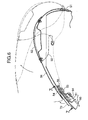
- Fig.6 is a sectional view taken along a line 6-6 in Fig.5;
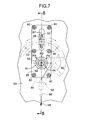
- Fig.7 is an enlarged sectional view taken along a line 7-7 in Fig.
- Fig.8 is a sectional view taken along a line 8-8 in Fig. 7
- Fig. 9 is a view taken through a portion of a case in an arrow 9 in Fig. 8
- Fig. 10 is an enlarged sectional view taken along a line 10-10 in Fig.4
- Fig. 11 is sectional view taken along a line 11-11 in Fig. 10
- Fig. 12 is a sectional view taken along a line 12-12 in Fig. 11.
- a vehicle body frame assembly F includes a pair of left and right main frames 15 extending longitudinally in a slightly rearward declined manner, a head pipe 16 mounted at front ends of the main frames 15, a pair of left and right down-frames 17 extending from the head pipe 16 in a rearward declined manner, a pair of left and right rear frames 18 integrally connected to rear ends of the down-frames 17 and extending rearwards in an upward and inclined manner, a pair of left and right center frames 19 which are integrally connected to rear ends of the main frames 15 and extend downwards and are connected to intermediate portions of the rear frames 18, and a seat stay 20 extending rearwards from the rear ends of the main frames 15 and connected to intermediate portions of the rear frames 18 at the rear of the connections of the center frames 19.
- a front fork 21 is steerably supported on the head pipe 16, and a front wheel WF is pivotally supported at a lower end of the front fork 21.
- a steering handlebar 22 is connected to an upper end of the front fork 21.
- a fuel tank 23 is mounted on the main frames 15, and a rear portion of the fuel tank 23 is disposed to cover a front portion of the seat stay 20.
- a power unit P comprising an engine E and a transmission M is mounted on the vehicle body frame assembly F below the fuel tank 23 and disposed in a region surrounded by the main frames 15, the down-frames 17 and the center frames 19.
- a swing arm 24 is vertically swingably supported at its front end on the transmission M, and a rear wheel WR is pivotally supported at a rear end of the swing arm 24.
- a rear fender 25 is mounted on the rear frames 18 to cover the rear wheel WR from above, and a rear cushion unit 26 is mounted between the rear fender 25 and a rear portion of the swing arm 24.
- An endless chain 29 is wound around a driven sprocket 27 coaxially mounted on the rear wheel WR and a driving sprocket 28 mounted on an output shaft of the transmission M, so that the rear wheel WR is driven in rotation by a power exhibited by the power unit P.
- a front seat 30 for a rider is disposed at the rear of the fuel tank 23 to cover a front portion of the rear fender 25 and detachably fixed to the vehicle body frame assembly F.
- a rear seat 31 for a tandem rider is disposed at the rear of the front seat 30 to cover the rear fender 25.
- the rear seat 31 is detachably connected to the front seat 30 and detachably mounted to the rear fender 25.
- saddle bag stays 32, 32 are disposed on laterally opposite sides of the rear wheel WR and fixed to the rear frames 18 of the vehicle body frame assembly F through the rear fender 25.
- Saddle bags 33, 33 are detachably mounted to the saddle bag stays 32, and lids 34, 34 are openably and closably mounted to the saddle bags 33.
- the saddle bag stay 32 includes a locking shaft section 32a extending in a longitudinal direction of the two-wheeled motor vehicle, a bag-supporting section 32b formed into an upward-opened substantially U-shape and connected to the locking shaft section 32a to form a rectangular shape by cooperation with the locking shaft section 32a, a first support arm 32c extending upwards from a front portion of the locking shaft section 32a, a second support arm 32d extending upwards from a longitudinally intermediate front portion of the locking shaft section 32a, a reinforcing arm 32e connecting the first and second support arms 32c and 32d to each other, and cylindrical bosses 32f and 32g provided at upper ends of the first and second support arms 32c and 32d, respectively.
- the locking shaft section 32a, the bag-supporting section 32b and the first support arm 32c in the saddle bag stay 32 are formed by bending a single pipe; a second support arm 32d formed of a pipe is welded to the locking shaft section 32a, and the reinforcing arm 32e formed of a pipe is welded at its opposite ends to the first and second support arms 32c and 32d.
- Bolts 35 are inserted through the bosses 32f and 32g with washers 36 interposed therebetween, and the saddle bag stay 32 is fixed to the rear fender 25 by threadedly fitting the bolts 35 into the rear fender 25 to tighten the bolts 35.
- a bar-shaped locking portion 37 is provided at a lower portion of the bag-supporting section 32b of the saddle bag 32 by welding an upper portion of a bar member extending vertically.
- the following bulges are provided on a surface of the saddle bag 33 opposed to the saddle bag stay 32: a first bulge 38 bulged to protrude partially into a portion of the saddle bag stay 32 surrounded by the locking shaft section 32a and the bag-supporting section 32b, a second bulge 39 bulged to form a first groove 42 extending rectilinearly between the second bulge 39 and an upper portion of the first bulge 38, so that the locking shaft section 32a can be inserted into the first groove 42, a third bulge 40 bulged to form a second groove 43 extending rectilinearly between the third bulge 40 and a lower portion of the first bulge 38, so that a lower portion of the bag-supporting section 32b closer to a rear portion can be inserted into the second groove 43, and a fourth bulge 41 bulged to form a third groove 44 of a substantially L-shape between the fourth bulge 41 and a front portion of the first bulge 38, so that a front portion of the bag-support
- the width of the first groove 42 is set at a value larger than the diameter of the locking shaft section 32a, and when the bag-supporting section 32b is inserted into the second and third grooves 43 and 44, the positions of the first and second bulges 38 and 39 are determined so that the locking shaft portion 32a is located in an upper portion of the first groove 42.
- the saddle bag 33 is provided with an engaging portion 45 disengageably engaging with the locking shaft section 32a of the saddle bag stay 32.
- the engaging portion 45 comprises a pair of engagement plates 46, 46 which are disposed at locations with a connection of the second support arm 32d to the locking shaft section 32a being sandwiched therebetween, the engagement plates being fastened to the saddle bag 33.
- Each of the engagement plates 46, 46 is fastened to the saddle bag 33 in such a manner that it engages with the locking shaft section 32a inserted into the upper portion of the first groove 42 from outside the first groove 42.
- Openings 47, 47 for enabling the insertion and withdrawal of the locking shaft section 32a into and from the first groove 42 are formed between the engagement plates 46, 46 and the first bulge 38, and an upper side of the first bulge 38 is formed as an inclined face 38a for smoothening the insertion and withdrawal of the locking shaft section 32a into and from the first groove 42 through the openings 47, 47.
- Elastic members 48 are secured to the saddle bag 33 to abut against a plurality points (at two points in the present embodiment) of the bag-supporting section 32b of the saddle bag stay 32 in order to prevent the damage of the saddle bag 33 due to the direct contact of the bag-supporting section 32b with the saddle bag 33.
- the saddle bag 33 is formed so that its upper portion is opened, and a front portion of the lid 34 capable of covering the upper portion of the saddle bag 33 is connected to the front portion of the saddle bag 33 through a hinge member 51 made of a material having a flexibility such as a leather material.
- the lid 34 is connected to the saddle bag 33, so that it can be operated in opening and closing movements between an opened position in which the hinge member 51 is flexed to open the upper portion of the saddle bag 33, as shown by a dashed line in Fig.6, and a closed position in which the upper portion of the saddle bag 33 is closed as shown by a solid line in Fig.6.
- a handle 52 for opening and closing the lid 34 and carrying about the saddle bag 33 removed from the saddle bag stay 32 is mounted to an outer surface of the upper portion of the lid 34, and a locking hook 53 is secured to an inner surface of a rear portion of the lid 34.
- a string 50 is placed between the lid 34 and the saddle bag 33 and hence, the lid 34 cannot be opened excessively largely by virtue of the string 50.
- the substantially U-shaped locking hook 53 is secured to a support plate 54, which is secured to the inner surface of the lid 34.
- a metal plate 55 abuts against the outer surface of the rear portion of the saddle bag 33 in a position corresponding to the locking hook 53, and case halves 56 and 57 forming a case 58 by cooperation with each other abut against the inner surface of the saddle bag 33 in such a manner that the saddle bag 33 is sandwiched between the case halves 56 and 57 and the metal plate 55.
- a plurality of welded nuts 59 are secured to the case halves 56 and 57, and a plurality of screw members 60 inserted through the metal plate 55, the saddle bag 33 and the case halves 56 and 57 from outside the metal plate 55 are threadedly engaged with welded nuts 59, whereby the metal plate 55 and the case halves 56 and 57 are fixed to the opposite sides, i.e., the surface and back of the saddle bag 33.
- a cylinder body 62 clamped between the saddle bag 33 and the case halves 56 is secured to the metal plate 55 in such a manner that its outer end protrudes to outside the metal plate 55 and its inner end protrudes into the case 58.
- the cylinder body 62 forms a key cylinder lock 61 as a key-operated means together with a rotor 64 inserted into the cylinder body 62 so that it can be turned by the insertion of a normal key 63, and a lever 65 secured to an inner end of the rotor 64.
- a key bore 66 for insertion of the key 63 is opened into an outer end of the rotor 64.
- Insertion bores 67 and 68 are provided in the metal plate 55 and the saddle bag 33 for permitting the locking hook 53 to be inserted into the case 58 when the lid 34 has been closed.
- the lever 65 at the inner end of the key cylinder lock 61 is provided with an engagement arm 69 which is capable of engaging disengageably with the locking hook 53 inserted in the case 58 through the insertion bores 67 and 68.
- Second and third turned positions P1, P2 and P3 are established at equal distances in the named order around a rotational axis for the rotor 64 and the lever 65 in the key cylinder lock 61, as shown in Fig. 7.
- the engagement arm 69 is formed so that it is disengaged from the locking hook 53 of the lid 34 which is in its closed position in a state in which the lever 65 is in the first turned position P1, but it is brought into engagement with the locking hook 53 in response to the turning movement of the lever 65 from the first turned position P1 to the second turned position P2 and moreover, the engagement with the locking hook 53 is maintained, despite the turning movement of the lever 65 from the second turned position P2 to the third turned position P3.
- a flap 70 made of a material having a flexibility such as a leather material is mounted to the lid 34, so that it covers the key cylinder lock 61 during closing of the lid 34, and it can be turned up as shown by a dashed line in Fig.6 when the key operation of the key cylinder lock 61 is carried out by the key 63.
- a locking means 75 is mounted below the saddle bag 33 in a side opposed to the saddle bag stay 32, so that it can be switched over between the engagement with the locking portion 37 provided on the saddle bag stay 32 and the disengagement from the locking portion 37.
- the locking means 75 includes an engagement member 76 capable of engaging with the locking portion 37, and a embracing member 77 capable of embracing the locking portion 37 together with the engagement member 76.
- the engagement member 76 and the embracing member 77 are turnably supported on a pair of bracket members 79 and 80 fastened to the saddle bag 33 along with a base plate 78 interposed between the bracket members 79 and 80 and the saddle bag 33 through a pair of support shafts 81 and 82 each having an axis parallel to the bar-shaped locking portion 37.
- Spring-receiving members 83 and 84 are disposed between both of the bracket members 79 and 80 on opposite sides of the engagement member 76 and the embracing member 77, so that a distance between the spring-receiving members 83 and 84 is maintained constant; and the support shafts 81 and 82 extend through the spring-receiving members 83 and 84.
- Limiting projections 83a, 83b, 83c and 83d are provided on the spring-receiving member 83 to protrude toward a side face of the spring-receiving member 83, 84 in order to maintain the positions of the engagement member 76 and the embracing member 77 along the support shafts 81 and 82 constant, and limiting projections 84a, 84b, 84c and 84d corresponding to the limiting projections 83a to 83d of the spring-receiving member 83 are also provided on the spring-receiving member 84 to protrude toward a side face of the spring-receiving member 83, 84.
- An outer periphery of the engagement member 76 is formed with a fitting recess 85 into which a substantial half of the bar-shaped locking portion 37 is fitted, and an abutment projection 86 leading to the fitting recess 85.
- the engagement member 76 makes the fitting recess 85 to bias in a direction of protrusion toward the saddle bag stay 32, i.e., in a direction of turning movement in a counterclockwise direction in Fig. 12 by a spring 87 mounted between the spring-receiving members 83 and 84.
- a limiting face 88 for limiting the end of turning movement of the engagement member 76 by a spring force of the spring 87 is formed in the spring-receiving member 84, and the engagement member 76 with the end of its turning movement limited by the limiting face 88 is in a state in which the abutment projection 86 is opposed to the locking portion 37 of the saddle bag stay 32, and when the saddle bag 33 is moved toward the saddle bag stay 32 in such a manner that the abutment projection 86 is brought into abutment against the locking portion 37, the engagement member 76 is turned against the spring force of the spring 87, whereby the substantial half of the locking portion 37 is fitted into the fitting recess 85.
- the embracing member 77 is provided at its outer periphery with (1) a first accommodating recess 89 depressed to accommodate a portion of the locking portion 37 having the substantial half fitted into the fitting recess 85, (2) a second accommodating recess 90 for accommodating the abutment projection 86 upon fitting of the substantial half of the locking portion 37 into the fitting recess 85, (3) a climbed-over projection 91 disposed between the first and second accommodating recesses 89 and 90 in such a manner that the abutment projection 86 accommodated in the second accommodating recess 90 abuts against the climbed-over projection 91, and (4) an urging projection 92 disposed on a side opposite from the climbed-over projection 91 with respect to the second accommodating recess 90.
- a spring 93 is mounted between the embracing member 77 and the spring-receiving members 83 and 84, so that the embracing member 77 is biased by a spring force of the spring 93 in a direction to bring the climbed-over projection 91 into abutment against the locking portion 37 having the substantial half fitted into the fitting recess 85 in the engagement member 76, i.e., in a direction of turning movement in a clockwise direction in Fig. 12.
- a limiting face 101 for limiting the end of turning movement of the embracing member 77 by a spring force of the spring 93 is formed on the spring-receiving member 83.
- a wire 94 is connected at one end to the lever 65 of the key cylinder lock 61 and inserted through a cylindrical sheath member 95 which is supported at one end on the case half 56 of the case 58 and at the other end on a support member 96 disposed in the vicinity of the locking means 75.
- the support member 96 is fixed to an inner surface of the third bulge 40 of the saddle bag 33.
- the other end of the wire 94 drawn from the other end of the sheath member 95 is disposed in a recess 98 provided in a saddle bag 33 in a region extending from the third bulge 40 to the locking means 75 through a grommet 99 mounted on the saddle bag 33.
- the recess 98 is covered with a covering portion 78a integrally provided on the base plate 78 fastened to the saddle bag 33, and a connecting arm 77a is integrally provided on the embracing member 77 to protrude through an opening 100 provided in the base plate 78 into the recess 98.
- an engagement piece 97 mounted at the other end of the wire 94 is engaged with a tip end of the connecting arm 77a.
- the locking means 75 and the lever 65 of the key cylinder lock 61 are connected to each other by the wire 94, and the wire 94 is connected to the lever 65 in such manner that it is pulled in response to the turning movement of the rotor 64 of the key cylinder lock 61 and the lever 65 from the second turned position P2 to the third turned position P3, but it is loosened by the turning movement of the lever 65 between the first and second turned positions P1 and P2.
- the engagement member 76 is located at the end of turning movement at which it is abutment against the limiting face 88 before it is brought into engagement with the locking portion 37 of the saddle bag stay 32, and the embracing member 77 is located at a turned position in which the climbed-over projection 91 is engaged with the abutment projection 86 of the engagement member 76 from behind.
- the wire 94 is disposed so that a pulling force is not applied to the wire 94 from the side of the locking means 75.
- the engagement member 76 When the saddle bag 33 is moved toward the saddle bag stay 32 in order to mount the saddle bag 33 to the saddle bag stay 32, the engagement member 76 is turned in the clockwise direction in Fig.12 against the spring force of the spring 87 by pushing the abutment projection 86 of the engagement member 76 by the locking portion 37, so that the locking portion 37 is fitted into the fitting recess 85.
- the abutment projection 86 climbs over the climbed-over projection 91, while slightly turning the embracing member 77 against the spring force of the spring 93 in the counterclockwise direction in Fig.12, i.e., in the direction to loosen the wire 94.
- the saddle bag 33 is turned about the locking shaft section 32a, so that the lower portion of the saddle bag 33 is moved away from the saddle bag stay 32, as shown by a dashed line in Fig. 5.
- the bag-supporting section 32b of the saddle bag stay 32 is disengaged from the second and third grooves 43 and 44 of the saddle bag 33, and the opening 47 in the engaging portion 45 is located immediately below the locking shaft section 32a. Therefore, the saddle bag 33 can be removed from the saddle bag stay 32 by lifting the saddle bag 33 upwards.
- the saddle bag 33 includes the locking means 75 capable of being switched over between the engagement and the disengagement with and from the locking portion 37 of the saddle bag stay 32, the key cylinder lock 61 for operating the locking means 75 in the direction to release the engagement with the locking portion 37 in response to the key operation, and the engaging portion 45 which disengageably engages with the locking shaft section 32a of the saddle bag stay 32, so that the disengagement thereof in the state in which the locking means 75 is in engagement with the locking portion 37 is made impossible, and the disengagement thereof in the state in which the locking means 75 is out of engagement with the locking portion 37 is made possible.
- the saddle bag 33 is fixedly mounted to the saddle bag stay 32 by bringing the engaging portion 45 into engagement with the locking shaft section 32a of the saddle bag stay 32 and bringing the locking means 75 into engagement with the locking portion 37 of the saddle bag stay 32. Moreover, when the locking means 75 is operated by the key operation of the key cylinder lock 61, so that the engagement thereof with the locking portion 37 is released, the engagement of the engaging portion 45 and the locking shaft section 32a can be released. Therefore, the saddle bag 33 can be removed easily from the saddle bag stay 32.
- the engaging portion 45 may be brought into engagement with the locking shaft section 32a and the locking means 75 may be brought into engagement with the locking portion 37.
- the engaging portion 45 may be brought into engagement with the locking shaft section 32a and the locking means 75 may be brought into engagement with the locking portion 37.
- the locking hook 53 is provided on the lid 34 openably and closably mounted on the saddle bag 33, and the key cylinder lock 61 having the lever 65 turned reversibly in response to the key operation is mounted on the saddle bag 33.
- the engagement arm 69 is formed so that it is disengaged from the locking hook 53 of the lid 34 which is in the closed position in the state in which the lever 65 is in the first turned position P1, but it is brought into engagement with the locking hook 53 in response to the turning movement of the lever 65 from the first turned position P1 to the second turned position P2.
- the engagement arm 69 is provided on the lever 65 in such a manner that the engagement with the locking hook 53 can be maintained despite the turning movement of the lever 65 from the second turned position P2 to the third turned position P3.
- the wire 94 which is pulled in response to the turning movement of the lever 65 from the second turned position P2 to the third turned position P3 is mounted between the locking means 75 and the lever 65 in such a manner that the locking means 75 can be operated to become disengaged from the saddle bag stay 32 by pulling the wire 94, and it is avoided that the power is transmitted to the locking means 75 by the turning movement of the lever 65 between the first and second turned positions P1 and P2.
- the lever 65 of the key cylinder lock 61 may be turned to the second turned position P2, and the engagement arm 69 provided on the lever 65 may be brought into engagement with the locking hook 53 of the lid 34.
- the key operation may be carried out so that the lever 65 is turned from the second turned position P2 to the first turned position P1.
- the lid 34 can be opened by releasing the engagement of the engagement arm 69 and the locking hook 53 with each other.
- the wire mounted between the lever 65 and the locking means 75 is merely loosened, and the power cannot be transmitted.
- the locking means 75 is maintained in engagement with the saddle bag stay 32.
- the switching-over between the possibility and impossibility of the demounting of the saddle bag 33 and the switching-over between the possibility and impossibility of opening and closing of the lid 34 can be distinguished from each other by the key operation of the single key cylinder lock 61, leading to a reduction in number of parts.
Landscapes
- Engineering & Computer Science (AREA)
- Mechanical Engineering (AREA)
- Purses, Travelling Bags, Baskets, Or Suitcases (AREA)
Abstract
Description
Claims (2)
- A structure of mounting a saddle bag in a two-wheeled motor vehicle including a saddle bag stay (32) disposed sideways of a rear wheel (WR) and fixed to a vehicle body frame assembly (F), and a saddle bag (33) mounted to said saddle bag stay (32), characterized in that said saddle bag stay (32) is provided with a locking shaft section (32a) and a locking portion (37), and said saddle bag (33) is provided with a locking means (75) which is capable of being switched over between the engagement and disengagement with and from said locking portion (37), a key-operated means (61) for operating said locking means (75) in a direction to release the engagement with said locking portion (37) in response to a key operation, and an engaging portion (45) disengageably engaging with said locking shaft section (32a), so that the disengagement threof in a state in which said locking means (75) is in engagement with the locking portion (37) is made impossible and the disengagement thereof in a state in which said locking means (75) is out of engagement with the locking portion (37) is made possible.
- A structure of mounting a saddle bag in a two-wheeled motor vehicle according to claim 1, wherein a lid (34) having a locking hook (53) is openably and closably mounted to said saddle bag (33); said saddle bag (33) is provided with said key-operated means (61) which has a lever (65) turned reversibly in response to the key operation and has first, second and third turned positions established at distances in the named order around a turning axis for said lever (65); said lever (65) is provided with an engagement arm (69) which is formed so as to be brought out of engagement with the locking hook (53) of said lid (34) which is in a closed position thereof in a state in which the lever is in the first turned position, and to be brought into engagement with said locking hook (53) in response to the turning movement of said lever (65) from the first turned position to the second turned position, said engagement arm (69) being provided in such a manner that the engagement with said locking hook (53) is maintained despite the turning movement of said lever (65) from the second turned position to the third turned position; and a wire (94) which is pulled in response to the turning movement of said lever (65) from the second turned position to the third turned position is mounted between the locking means (75) and the lever (65) in such a manner that said locking means (75) is operated to become disengaged from the saddle bag stay (32) by pulling said wire (94), and it is avoided that a power be transmitted to said locking means (75) by the turning movement of said lever (65) between the first and second turned positions.
Applications Claiming Priority (5)
| Application Number | Priority Date | Filing Date | Title |
|---|---|---|---|
| JP2001074505 | 2001-03-15 | ||
| JP2001074505A JP3569687B2 (en) | 2001-03-15 | 2001-03-15 | Saddle bag mounting structure for motorcycle |
| JP2001074506A JP3542332B2 (en) | 2001-03-15 | 2001-03-15 | Saddle bag device for motorcycle |
| JP2001074506 | 2001-03-15 | ||
| PCT/JP2002/001569 WO2002074613A1 (en) | 2001-03-15 | 2002-02-21 | Saddle bag installation structure of motorcycle |
Publications (3)
| Publication Number | Publication Date |
|---|---|
| EP1369344A1 true EP1369344A1 (en) | 2003-12-10 |
| EP1369344A4 EP1369344A4 (en) | 2006-08-30 |
| EP1369344B1 EP1369344B1 (en) | 2009-09-16 |
Family
ID=26611349
Family Applications (1)
| Application Number | Title | Priority Date | Filing Date |
|---|---|---|---|
| EP02700685A Expired - Lifetime EP1369344B1 (en) | 2001-03-15 | 2002-02-21 | Structure for mounting a saddle bag on a motorcycle |
Country Status (4)
| Country | Link |
|---|---|
| US (1) | US7207470B2 (en) |
| EP (1) | EP1369344B1 (en) |
| DE (1) | DE60233721D1 (en) |
| WO (1) | WO2002074613A1 (en) |
Cited By (10)
| Publication number | Priority date | Publication date | Assignee | Title |
|---|---|---|---|---|
| WO2005118382A1 (en) * | 2004-05-26 | 2005-12-15 | Bayerische Motoren Werke Aktiengesellschaft | Motorcycle comprising a holding device for a lateral case |
| EP1921001A1 (en) * | 2006-11-13 | 2008-05-14 | Sau Leong Lim | Luggage carrier for a two wheeled vehicle |
| ES2301356A1 (en) * | 2006-05-11 | 2008-06-16 | Nad S.L. | Lock device for motorcycle cases |
| EP2033883A1 (en) | 2007-09-04 | 2009-03-11 | Yamaha Motor Research & Development Europe s.r.l. | A case assembly for a motor cycle and a motor cycle equipped with such a case assembly |
| DE102004020592B4 (en) * | 2003-05-23 | 2013-04-04 | Honda Motor Co., Ltd. | Motorcycle saddle bags attachment device |
| ITMI20121405A1 (en) * | 2012-08-07 | 2014-02-08 | Givi Srl | "SUITCASE FOR MOTORCYCLES AND ITS OPENING / CLOSING AND LOCKING / RELEASING SYSTEM COMPARED TO A FIXED STRUCTURE OF A MOTORCYCLE" |
| WO2014024141A1 (en) * | 2012-08-07 | 2014-02-13 | Givi S.R.L. | Case for motorcycles |
| IT201900005450A1 (en) * | 2019-04-09 | 2020-10-09 | Givi S P A | SUITCASE OF A MOTORCYCLE. |
| IT201900024955A1 (en) * | 2019-12-20 | 2021-06-20 | Piaggio & C Spa | Removable storage box for ride-on saddle vehicle |
| EP4032792A1 (en) * | 2021-01-25 | 2022-07-27 | Kawasaki Motors, Ltd. | Pannier and vehicle including the same |
Families Citing this family (26)
| Publication number | Priority date | Publication date | Assignee | Title |
|---|---|---|---|---|
| ITVI20040217A1 (en) | 2004-09-17 | 2004-12-17 | Selle Royal Spa | QUICK COUPLING STRUCTURE FOR BICYCLE SADDLE |
| DE102005031716A1 (en) * | 2005-06-07 | 2006-12-14 | Bayerische Motoren Werke Ag | Luggage container for a motorcycle |
| ITMI20051973A1 (en) * | 2005-10-18 | 2007-04-19 | Givi Srl | ASSEMBLY OF A VAIGIA PEER MOTORCYCLE WITH A PERFECT FIXING SYSTEM |
| US7870985B2 (en) * | 2006-07-28 | 2011-01-18 | Steven Mark King | Carrying apparatus for cycle-type vehicle |
| US7766201B2 (en) * | 2006-08-16 | 2010-08-03 | Louis Chuang | Device for attaching a bag to a luggage carrier |
| US20080083801A1 (en) * | 2006-10-09 | 2008-04-10 | Harley-Davidson Motor Company Group, Inc. | Motorcycle saddlebag mounting system |
| DE102008030595A1 (en) * | 2007-06-29 | 2009-01-22 | Harley-Davidson Motor Company Group, Inc., Milwaukee | Saddlebag mounting system for a motorcycle |
| US20090014486A1 (en) * | 2007-07-12 | 2009-01-15 | Johnny Humphreys | Golf bag motorcycle transport system |
| US8646669B2 (en) * | 2008-02-15 | 2014-02-11 | Blackbird Dynamics, Llc | Cantilevered storage unit mount for vehicles |
| US8579169B2 (en) * | 2008-07-31 | 2013-11-12 | Indian Motorcycle Company | Mounting assembly for a vehicle accessory |
| JP5091804B2 (en) * | 2008-08-22 | 2012-12-05 | 本田技研工業株式会社 | Saddle bag mounting structure for motorcycles |
| US20100264183A1 (en) * | 2009-04-15 | 2010-10-21 | Kaczowski Michael J | Motorcycle saddlebag |
| DE102009022652A1 (en) | 2009-05-26 | 2010-12-09 | Philipp Gläser | Assistance system for the control of a ship |
| US8272460B2 (en) | 2009-06-04 | 2012-09-25 | Polaris Industries Inc. | Two-wheeled vehicle |
| USD624853S1 (en) | 2009-06-04 | 2010-10-05 | Polaris Industries Inc. | Motorcycle |
| US8151925B2 (en) | 2009-06-04 | 2012-04-10 | Polaris Industries Inc. | Two-wheeled vehicle |
| IT1402523B1 (en) * | 2010-10-19 | 2013-09-13 | Givi S R L Unipersonale | INTEGRATED SYSTEM FOR THE OPENING AND CLOSING OF A SUITCASE FOR MOTORCYCLES AND FOR THE ATTACHMENT AND RELEASE OF SUCH SUITABLE FOR THE MOTORCYCLE |
| US9402477B2 (en) | 2012-12-17 | 2016-08-02 | Melissa Shih Hwai Chang | Supplementary organizer and storage device |
| USD722945S1 (en) * | 2013-06-05 | 2015-02-24 | John Evans Richie | Saddlebag extensions |
| EP3077280A4 (en) | 2013-12-05 | 2017-09-27 | Milsco Manufacturing Company a Unit of Jason Incorporated | Composite fiber saddlebag, saddle liner, and method |
| WO2016046773A1 (en) * | 2014-09-23 | 2016-03-31 | Bombardier Recreational Products Inc. | Storage container assembly for a vehicle |
| US10029752B2 (en) | 2014-10-28 | 2018-07-24 | Douglas James Gilles, JR. | Saddlebag support apparatus |
| JP6799952B2 (en) * | 2016-06-27 | 2020-12-16 | 川崎重工業株式会社 | Pannier mounting structure for saddle-mounted vehicles |
| MX2019005941A (en) * | 2018-05-24 | 2020-02-05 | Cnh Ind America Llc | Storage tank assembly for a work vehicle. |
| USD906182S1 (en) | 2018-11-13 | 2020-12-29 | Indian Motorcycle International, LLC | Motorcycle |
| IT202000022063A1 (en) * | 2020-09-18 | 2022-03-18 | Givi S P A | SPACER |
Family Cites Families (10)
| Publication number | Priority date | Publication date | Assignee | Title |
|---|---|---|---|---|
| ES242135Y (en) * | 1976-07-26 | 1979-11-16 | A PERFECTED CONTAINMENT FRAME DEVICE. | |
| GB2047644A (en) * | 1979-05-09 | 1980-12-03 | Rickman Metisse Holdings Ltd | Case for mounting on motor cycles |
| JPS5624390A (en) | 1979-12-05 | 1981-03-07 | Mitsubishi Electric Corp | Character pattern memory system |
| HU183207B (en) | 1980-09-10 | 1984-04-28 | Richter Gedeon Vegyeszet | Process for preparing apovincaminic acid esters |
| JPS5758569A (en) * | 1980-09-22 | 1982-04-08 | Honda Motor Co Ltd | Locking device for car body upper section and car body side section of autobicycle |
| DE3226445C2 (en) | 1982-07-15 | 1986-04-10 | Bayerische Motoren Werke AG, 8000 München | Support element which can be fastened to a frame of a motorcycle or the like for receiving a motorcycle case or the like |
| DE19827973B4 (en) | 1998-06-23 | 2006-09-28 | Rixen & Kaul Gmbh | Fastening device for luggage containers on motorcycles and luggage containers |
| US6053384A (en) * | 1998-09-11 | 2000-04-25 | Bachman; Rick A. | Mounting system for motorcycle saddle bags |
| WO2001012496A1 (en) | 1999-08-13 | 2001-02-22 | Livio Ricci | Suitcase for motorcycles, or similar, with double function locking device, and referring locking method |
| EP1065139B1 (en) | 2000-03-21 | 2002-06-12 | GI.VI. s.r.l. | Motorbike transport case having release elements on the lid thereof |
-
2002
- 2002-02-21 US US10/471,711 patent/US7207470B2/en not_active Expired - Fee Related
- 2002-02-21 WO PCT/JP2002/001569 patent/WO2002074613A1/en not_active Ceased
- 2002-02-21 EP EP02700685A patent/EP1369344B1/en not_active Expired - Lifetime
- 2002-02-21 DE DE60233721T patent/DE60233721D1/en not_active Expired - Lifetime
Cited By (19)
| Publication number | Priority date | Publication date | Assignee | Title |
|---|---|---|---|---|
| DE102004020592B4 (en) * | 2003-05-23 | 2013-04-04 | Honda Motor Co., Ltd. | Motorcycle saddle bags attachment device |
| WO2005118382A1 (en) * | 2004-05-26 | 2005-12-15 | Bayerische Motoren Werke Aktiengesellschaft | Motorcycle comprising a holding device for a lateral case |
| ES2301356A1 (en) * | 2006-05-11 | 2008-06-16 | Nad S.L. | Lock device for motorcycle cases |
| ES2301356B1 (en) * | 2006-05-11 | 2009-03-16 | Nad S.L. | LOCK DEVICE FOR MOTORCYCLE CASES. |
| US9248878B2 (en) | 2006-11-13 | 2016-02-02 | Sau Leong Lim | Luggage carrier for a two wheeled vehicle |
| EP1921001A1 (en) * | 2006-11-13 | 2008-05-14 | Sau Leong Lim | Luggage carrier for a two wheeled vehicle |
| WO2008060245A1 (en) * | 2006-11-13 | 2008-05-22 | Sau Leong Lim | Luggage carrier for a two wheeled vehicle |
| CN101311058B (en) * | 2006-11-13 | 2012-05-23 | 林绍龙 | Luggage carrier for a two wheeled vehicle |
| EP2033883A1 (en) | 2007-09-04 | 2009-03-11 | Yamaha Motor Research & Development Europe s.r.l. | A case assembly for a motor cycle and a motor cycle equipped with such a case assembly |
| ITMI20121405A1 (en) * | 2012-08-07 | 2014-02-08 | Givi Srl | "SUITCASE FOR MOTORCYCLES AND ITS OPENING / CLOSING AND LOCKING / RELEASING SYSTEM COMPARED TO A FIXED STRUCTURE OF A MOTORCYCLE" |
| WO2014024141A1 (en) * | 2012-08-07 | 2014-02-13 | Givi S.R.L. | Case for motorcycles |
| US9650096B2 (en) | 2012-08-07 | 2017-05-16 | Givi S.R.L. | Case for motorcycles |
| IT201900005450A1 (en) * | 2019-04-09 | 2020-10-09 | Givi S P A | SUITCASE OF A MOTORCYCLE. |
| WO2020208520A1 (en) * | 2019-04-09 | 2020-10-15 | Givi S.P.A. | A luggage of a motorcycle |
| US11623708B2 (en) | 2019-04-09 | 2023-04-11 | Givi S.P.A. | Luggage of a motorcycle |
| IT201900024955A1 (en) * | 2019-12-20 | 2021-06-20 | Piaggio & C Spa | Removable storage box for ride-on saddle vehicle |
| EP3838725A1 (en) * | 2019-12-20 | 2021-06-23 | PIAGGIO & C. S.p.A. | Removable storage container for saddle riding-type vehicle |
| EP4032792A1 (en) * | 2021-01-25 | 2022-07-27 | Kawasaki Motors, Ltd. | Pannier and vehicle including the same |
| US12233981B2 (en) | 2021-01-25 | 2025-02-25 | Kawasaki Motors, Ltd. | Pannier and vehicle including the same |
Also Published As
| Publication number | Publication date |
|---|---|
| WO2002074613A1 (en) | 2002-09-26 |
| US7207470B2 (en) | 2007-04-24 |
| EP1369344B1 (en) | 2009-09-16 |
| DE60233721D1 (en) | 2009-10-29 |
| US20040149792A1 (en) | 2004-08-05 |
| EP1369344A4 (en) | 2006-08-30 |
Similar Documents
| Publication | Publication Date | Title |
|---|---|---|
| EP1369344B1 (en) | Structure for mounting a saddle bag on a motorcycle | |
| JP4252876B2 (en) | Motorcycle | |
| JP4332010B2 (en) | Scooter-type vehicle article storage structure | |
| US8845154B2 (en) | Motorcycle | |
| US7448663B2 (en) | Guard structure for vehicle seat lock | |
| JP4119344B2 (en) | Motorcycle | |
| US20010022462A1 (en) | Seat fitting structure for motor scooter type vehicle | |
| JP2005119421A (en) | Remote control device for scooter type vehicle | |
| JP2005119420A (en) | Remote control device for light vehicles | |
| KR100546858B1 (en) | Structure for article receiving portion of vehicle | |
| JP3569687B2 (en) | Saddle bag mounting structure for motorcycle | |
| EP1369345B1 (en) | Forward disposed part installation structure of motorcycle | |
| US7316410B2 (en) | Frame structure of small vehicle | |
| EP1524178B1 (en) | Remote control apparatus for a light vehicle | |
| KR100472328B1 (en) | Steering lock mechanism of motorcycle | |
| EP1361144B1 (en) | Headlight apparatus for motorcycles | |
| JP2003118668A (en) | Lighting equipment for storage boxes for small vehicles | |
| JP2004099007A (en) | Motorcycle seat mounting structure | |
| JP4010762B2 (en) | Bicycle handle lever | |
| JP3542332B2 (en) | Saddle bag device for motorcycle | |
| JP4083322B2 (en) | Motorcycle seat lock mechanism | |
| JP4421751B2 (en) | Vehicle handle lock device | |
| JP4145766B2 (en) | Scooter type vehicle | |
| JP2009208622A (en) | Swing arm structure for motorcycle | |
| JP2004042862A (en) | Motorcycle seat opening and closing structure |
Legal Events
| Date | Code | Title | Description |
|---|---|---|---|
| PUAI | Public reference made under article 153(3) epc to a published international application that has entered the european phase |
Free format text: ORIGINAL CODE: 0009012 |
|
| 17P | Request for examination filed |
Effective date: 20030912 |
|
| AK | Designated contracting states |
Kind code of ref document: A1 Designated state(s): AT BE CH CY DE DK ES FI FR GB GR IE IT LI LU MC NL PT SE TR |
|
| A4 | Supplementary search report drawn up and despatched |
Effective date: 20060731 |
|
| 17Q | First examination report despatched |
Effective date: 20061020 |
|
| GRAP | Despatch of communication of intention to grant a patent |
Free format text: ORIGINAL CODE: EPIDOSNIGR1 |
|
| RTI1 | Title (correction) |
Free format text: STRUCTURE FOR MOUNTING A SADDLE BAG ON A MOTORCYCLE |
|
| GRAS | Grant fee paid |
Free format text: ORIGINAL CODE: EPIDOSNIGR3 |
|
| GRAA | (expected) grant |
Free format text: ORIGINAL CODE: 0009210 |
|
| AK | Designated contracting states |
Kind code of ref document: B1 Designated state(s): BE DE FR GB IT |
|
| REG | Reference to a national code |
Ref country code: GB Ref legal event code: FG4D |
|
| REF | Corresponds to: |
Ref document number: 60233721 Country of ref document: DE Date of ref document: 20091029 Kind code of ref document: P |
|
| RAP2 | Party data changed (patent owner data changed or rights of a patent transferred) |
Owner name: HONDA ACCESS CORPORATION |
|
| PG25 | Lapsed in a contracting state [announced via postgrant information from national office to epo] |
Ref country code: BE Free format text: LAPSE BECAUSE OF FAILURE TO SUBMIT A TRANSLATION OF THE DESCRIPTION OR TO PAY THE FEE WITHIN THE PRESCRIBED TIME-LIMIT Effective date: 20090916 |
|
| PLBE | No opposition filed within time limit |
Free format text: ORIGINAL CODE: 0009261 |
|
| STAA | Information on the status of an ep patent application or granted ep patent |
Free format text: STATUS: NO OPPOSITION FILED WITHIN TIME LIMIT |
|
| 26N | No opposition filed |
Effective date: 20100617 |
|
| REG | Reference to a national code |
Ref country code: FR Ref legal event code: ST Effective date: 20101029 |
|
| PG25 | Lapsed in a contracting state [announced via postgrant information from national office to epo] |
Ref country code: FR Free format text: LAPSE BECAUSE OF NON-PAYMENT OF DUE FEES Effective date: 20100301 |
|
| PG25 | Lapsed in a contracting state [announced via postgrant information from national office to epo] |
Ref country code: IT Free format text: LAPSE BECAUSE OF FAILURE TO SUBMIT A TRANSLATION OF THE DESCRIPTION OR TO PAY THE FEE WITHIN THE PRESCRIBED TIME-LIMIT Effective date: 20090916 |
|
| PGFP | Annual fee paid to national office [announced via postgrant information from national office to epo] |
Ref country code: DE Payment date: 20101130 Year of fee payment: 10 |
|
| PGFP | Annual fee paid to national office [announced via postgrant information from national office to epo] |
Ref country code: GB Payment date: 20110211 Year of fee payment: 10 |
|
| REG | Reference to a national code |
Ref country code: GB Ref legal event code: 732E Free format text: REGISTERED BETWEEN 20110825 AND 20110831 |
|
| REG | Reference to a national code |
Ref country code: DE Ref legal event code: R081 Ref document number: 60233721 Country of ref document: DE Owner name: HONDA MOTOR CO., LTD., JP Free format text: FORMER OWNER: HONDA ACCESS CORP., NIIZA, JP Effective date: 20110923 Ref country code: DE Ref legal event code: R081 Ref document number: 60233721 Country of ref document: DE Owner name: HONDA MOTOR CO., LTD., JP Free format text: FORMER OWNER: HONDA ACCESS CORP., NIIZA, SAITAMA, JP Effective date: 20110923 |
|
| GBPC | Gb: european patent ceased through non-payment of renewal fee |
Effective date: 20120221 |
|
| REG | Reference to a national code |
Ref country code: DE Ref legal event code: R119 Ref document number: 60233721 Country of ref document: DE Effective date: 20120901 |
|
| PG25 | Lapsed in a contracting state [announced via postgrant information from national office to epo] |
Ref country code: GB Free format text: LAPSE BECAUSE OF NON-PAYMENT OF DUE FEES Effective date: 20120221 |
|
| PG25 | Lapsed in a contracting state [announced via postgrant information from national office to epo] |
Ref country code: DE Free format text: LAPSE BECAUSE OF NON-PAYMENT OF DUE FEES Effective date: 20120901 |