EP1369339A2 - Electric power steering apparatus - Google Patents
Electric power steering apparatus Download PDFInfo
- Publication number
- EP1369339A2 EP1369339A2 EP03011862A EP03011862A EP1369339A2 EP 1369339 A2 EP1369339 A2 EP 1369339A2 EP 03011862 A EP03011862 A EP 03011862A EP 03011862 A EP03011862 A EP 03011862A EP 1369339 A2 EP1369339 A2 EP 1369339A2
- Authority
- EP
- European Patent Office
- Prior art keywords
- output shaft
- target plate
- input shaft
- input
- torque
- Prior art date
- Legal status (The legal status is an assumption and is not a legal conclusion. Google has not performed a legal analysis and makes no representation as to the accuracy of the status listed.)
- Granted
Links
Images

Classifications
-
- B—PERFORMING OPERATIONS; TRANSPORTING
- B62—LAND VEHICLES FOR TRAVELLING OTHERWISE THAN ON RAILS
- B62D—MOTOR VEHICLES; TRAILERS
- B62D6/00—Arrangements for automatically controlling steering depending on driving conditions sensed and responded to, e.g. control circuits
- B62D6/08—Arrangements for automatically controlling steering depending on driving conditions sensed and responded to, e.g. control circuits responsive only to driver input torque
- B62D6/10—Arrangements for automatically controlling steering depending on driving conditions sensed and responded to, e.g. control circuits responsive only to driver input torque characterised by means for sensing or determining torque
-
- B—PERFORMING OPERATIONS; TRANSPORTING
- B62—LAND VEHICLES FOR TRAVELLING OTHERWISE THAN ON RAILS
- B62D—MOTOR VEHICLES; TRAILERS
- B62D5/00—Power-assisted or power-driven steering
- B62D5/04—Power-assisted or power-driven steering electrical, e.g. using an electric servo-motor connected to, or forming part of, the steering gear
- B62D5/0457—Power-assisted or power-driven steering electrical, e.g. using an electric servo-motor connected to, or forming part of, the steering gear characterised by control features of the drive means as such
- B62D5/046—Controlling the motor
- B62D5/0472—Controlling the motor for damping vibrations
-
- G—PHYSICS
- G01—MEASURING; TESTING
- G01L—MEASURING FORCE, STRESS, TORQUE, WORK, MECHANICAL POWER, MECHANICAL EFFICIENCY, OR FLUID PRESSURE
- G01L3/00—Measuring torque, work, mechanical power, or mechanical efficiency, in general
- G01L3/02—Rotary-transmission dynamometers
- G01L3/04—Rotary-transmission dynamometers wherein the torque-transmitting element comprises a torsionally-flexible shaft
- G01L3/10—Rotary-transmission dynamometers wherein the torque-transmitting element comprises a torsionally-flexible shaft involving electric or magnetic means for indicating
- G01L3/101—Rotary-transmission dynamometers wherein the torque-transmitting element comprises a torsionally-flexible shaft involving electric or magnetic means for indicating involving magnetic or electromagnetic means
- G01L3/104—Rotary-transmission dynamometers wherein the torque-transmitting element comprises a torsionally-flexible shaft involving electric or magnetic means for indicating involving magnetic or electromagnetic means involving permanent magnets
Definitions
- the present invention relates to a power steering apparatus.
- torque T is calculated from a relative difference between steering angles in an input shaft of the input side and an output shaft of the output side from a torsion bar in a steering shaft. Then, when it is determined that the torque T is backward input torque based on each angular speed and vehicle speed of the input shaft and the output shaft, a sign (+, -) of the torque T is reversed and the torque T is set to backward assist torque, and a motor for steering assistance is driven in order to generate it.
- the case that the torque T becomes the backward input torque is, for example, the case that disturbance from a road surface is received in a steering direction of wheels in a steering holding state at the time of straight travel.
- the backward input torque due to the disturbance is offset by driving force of the motor to prevent the disturbance from propagating to a handle.
- unnatural steering feeling may be given to a driver by performing a backward assist operation in which the disturbance is offset regardless of driver's intention. Since the disturbance hardly propagates to the handle, it is difficult for the driver to accurately grasp a state of the road surface. Giving an extreme example, there is little difference between the case of running a snowy road with low frictional resistance of the road surface in a steering direction and the case of running a gravel road with high frictional resistance in the disturbance propagating to the driver through the handle. That is, information about the road surface through the handle does not propagate to the driver accurately.
- an object of the invention is to provide an electric power steering apparatus for propagating disturbance to a handle moderately while suppressing the disturbance.
- the invention is characterized by having the following arrangement.
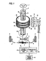
- Fig. 1 is a diagram schematically showing a structure of an electric power steering apparatus according to an embodiment of the invention.
- the apparatus is an apparatus which is mounted in, for example, an automobile, and in which a steering shaft 3 is disposed between a steering member (handle) 1 and a pinion 2.
- the steering shaft 3 includes a torsion bar 31 provided in the center, an input shaft 32 fixed in the input side (upper) of the torsion bar 31, an output shaft 33 fixed in the output side (lower) of the torsion bar 31, a first target plate 34 fitted outside the input shaft 32, and a second target plate 35 and a third target plate 36 fixed in the output shaft 33.
- the input shaft 32 and the output shaft 33 are coaxially placed each other but are not directly connected each other and are connected through the torsion bar 31.
- the first target plate 34, the second target plate 35 and the third target plate 36 are coaxially placed one another.
- Each of the target plates 34 to 36 described above has a form of spur gear shape, and outer circumferential teeth made of magnetic material form an uneven target at regular intervals circumferentially.
- the number of teeth of the first target plate 34 is the same number N (for example, 36) as that of teeth of the second target plate 35, and the number of teeth of the third target plate 36 is the number (for example, 35) which is mutually prime (without having common divisors other than 1) to N.
- each of the target plates 34 to 36 described above is separate from the input shaft 32 or the output shaft 33 and has a structure fitted in the outside, but the input shaft 32 or the output shaft 33 may be made of magnetic material and may be formed integrally to the corresponding target plates 34 to 36.
- a worm wheel 4 is attached to the output shaft 33 and this worm wheel meshes with a worm 5 attached to an output shaft of a motor 6. Rotation of the motor 6 is transmitted to the pinion 2 through the worm 5 and the worm wheel 4 and results in steering assistance force. Rotation of the pinion 2 is converted into linear motion of a rack 7 and steering wheels 9 are steered through right and left tie rods 8.
- Six magnetic sensors A1, B1, A2, B2, A3, B3 to which the outer circumferential teeth of each of the target plates 34 to 36 described above are opposed are placed in three rows and two columns and these sensors are held in a sensor box 10.
- the sensor box 10 is fixed in a predetermined position of an automobile body.
- the sensors A1, B1 opposed to the first target plate 34 are offset from each other in a circumferential direction of the first target plate 34.
- the sensors A2, B2 opposed to the second target plate 35 are offset from each other in the circumferential direction thereof
- the sensors A3 and B3 opposed to the third target plate 36 are offset from each other in the circumferential direction thereof.
- the magnetic sensors A1 to A3, B1 to B3 an element having characteristics in which resistance changes by action of a magnetic field such as a magnetoresistive element (MR element) is used.
- the magnetic sensors A1 to A3, B1 to B3 output a signal voltage periodically changing in response to unevenness of the outer circumference of each of the opposite target plates 34 to 36. Therefore, output from the magnetic sensors A1, B1 corresponds to angular displacement of the input shaft 32 and the first target plate 34, and output from the magnetic sensors A2, B2 corresponds to angular displacement of the output shaft 33 and the second target plate 35. Similarly, output from the magnetic sensors A3, B3 corresponds to angular displacement of the output shaft 33 and the third target plate 36.
- MR element magnetoresistive element
- the outputs from the magnetic sensors A1 to A3, B1 to B3 are inputted to a controller 21 into which a CPU is built.
- the controller 21 has functions of a computation unit 21a and a driving control unit 21b, which are achieved by software processing.
- angular displacement ⁇ 1 of the input shaft 32 and the first target plate 34 is calculated from the output of the magnetic sensors A1, B1.
- angular displacement ⁇ 2 of the output shaft 33 and the second target plate 35 is calculated from the output of the magnetic sensors A2, B2.
- a signal of a vehicle speed detected by a vehicle speed sensor 22 is inputted to the controller 21.
- the motor 6 is driven and controlled by the controller 21.
- Fig. 2 is a diagram schematically showing the torsion bar 31, the input shaft 32, the output shaft 33, each of the target plates 34 to 36, and the magnetic sensors A1 to A3, B1 to B3.
- the first target plate 34 rotates with the input shaft 32, and output signals of the magnetic sensors A1, B1 change depending on unevenness of the outer circumference. That is, the first target plate 34 and the magnetic sensors A1, B1 construct an input shaft rotation detection unit for outputting a signal in response to rotation of the input shaft 32.
- a phase difference between placements of the magnetic sensors A1 and B1 in an electrical angle with respect to opposite unevenness is set so as to be ⁇ /2. Therefore, output signals (voltages) from the magnetic sensors A1, B1 always shift by ⁇ /2 as shown in Fig. 3.
- the second target plate 35 rotates with the output shaft 33, and output signals of the magnetic sensors A2, B2 change depending on unevenness of the outer circumference . That is, the second target plate 35 and the magnetic sensors A2, B2 construct an output shaft rotation detection unit for outputting a signal in response to rotation of the output shaft 33. Similarly, a phase difference between placements of the magnetic sensors A2 and B2 in an electrical angle with respect to opposite unevenness is set so as to be ⁇ /2.
- the third target plate 36 rotates with the output shaft 33, and output signals of the magnetic sensors A 3 , B3 change depending on unevenness of the outer circumference.
- positions of the magnetic sensors A3, B3 in a circumferential direction are the same as those of the magnetic sensors A2, B2, respectively.
- the absolute rotation position of the output shaft 33 can be determined from the phase shift.
- a table is built into the controller 21. Further, a rotating direction of the output shaft 33 can be determined based on this information.
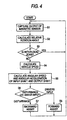
- Fig. 4 is one example of a flowchart of an operation performed in the controller 21.
- steps S1 to S5 are an operation acting as the computation means 21a and steps S6 to S8 are operation acting as the driving control unit 21b.
- step S1 the controller 21 captures each output of the magnetic sensors A1 to A3, B1 to B3 at a predetermined sampling period and obtains the above-mentioned angular displacements ⁇ 1, ⁇ 2 based on this and thereafter in step 2, a relative rotation angle between the input shaft 32 and the output shaft 33, that is, an absolute value of ( ⁇ 1- ⁇ 2) is calculated.
- This value is a torsion angle of the torsion bar 31 and corresponds to torque transmitted between the input shaft 32 and the output shaft 33.
- step S3 the controller 21 decides whether or not this value is within the range of a predetermined dead zone.
- step S3 the flowchart returns to step S1 and when it is beyond the range, the flowchart proceeds to step S4.
- the controller 21 calculates a vehicle speed from the output of the vehicle speed sensor 22 (step 54), and respectively differentiates the angular displacements ⁇ 1, ⁇ 2 with respect to time to calculate angular speeds ⁇ 1, ⁇ 2, and further differentiates the angular speeds to calculate angular accelerations ⁇ 1', ⁇ 2' (step S5).
- the controller 21 determines which of the input shaft 32 and the output shaft 33 is in a dynamically superior state from information based on the angular displacements with respect to each of the input shaft 32 and the output shaft 33 (step S6).
- “dynamically superior” means more active.
- the controller determines whether torque applied between the input shaft 32 and the output shaft 33 exceeding the dead zone is torque caused by disturbance propagating from a road surface or torque caused by of driver input, that is, handle manipulation of a driver. This determination is made by comparison of the angular speeds or comparison of the angular accelerations.
- the angular speed has the same meaning as that of a frequency of the angular displacement, and this is because the more active shaft generally has a higher frequency.
- the angular acceleration means force applied in a direction of the angular displacement, and this is because the more active shaft generally applies strong force.
- the controller 21 determines that it is the disturbance in the case of ⁇ 1 ⁇ 2 or ⁇ 1' ⁇ 2', and an operation of a backward assist is performed (step S7), and in the case of ⁇ 1 ⁇ 2 and ⁇ 1' ⁇ 2', it is determined that it is the driver input and an operation of a forward assist is performed (step 58).
- the forward assist means that assist force is applied from the motor 6 in a direction of the driver input and in this case, the assist force is applied until the relative rotation angle reaches the range of the dead zone.
- a vehicle speed is considered and steering assistance of speed responsive type is performed.
- the backward assist means that steering assist force is applied from the motor 6 in a direction of reducing torque caused by the disturbance.
- the case that deterioration of steering feeling due to the disturbance becomes a problem is at the time of high speed travel. Therefore, when the vehicle speed does not reach a constant speed, it may be processed so as to pass up the operation of the backward assist in step S7.
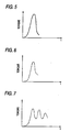
- Fig. 5 is a graph showing a torque waveform of disturbance suffered in a steering direction of wheels at the time when an automobile passes on an iron plate of a joint of, for example, an express highway, and the axis of abscissa shows time and the axis of ordinate shows torque of disturbance.
- this waveform is a waveform of the case that the backward assist is not considered.
- the controller 21 With respect to such disturbance, the controller 21 generates backward assist torque as shown in Fig. 6 substantially.
- step S7 a time integral value of torque (relative torque between the input shaft 32 and the output shaft 33) to that point in time is calculated based on the relative rotation angle, and the motor 6 is driven so that torque resulting in a time integral value (for example, 80 to 90 %) slightly smaller than its value is generated in a backward assist direction.
- torque resulting in a time integral value slightly smaller than a time integral value of disturbance torque at that point in time continues to be given sequentially in the backward assist direction and the disturbance is relieved.
- the relative rotation angle reaches the range of the dead zone, the backward assist is completed.
- the amount for example, 10 to 20 %) other than the torque offset by the backward assist among the disturbance torque, a driver bears this amount by natural holding steering force.
- occurrence of the disturbance is propagated to the driver slightly while canceling most of the disturbance by the backward assist. Therefore, while suppressing strong disturbance resulting in discomfort or fatigue to the driver, the disturbance is propagated to a handle moderately and the driver can grasp information about a road surface.
- the disturbance in the case of giving a backward assist for immediately offsetting disturbance torque as an instantaneous value, the disturbance is resistant to propagation to the handle as well as it becomes unnatural steering feeling conversely.
- a backward assist based on disturbance torque as an integral value as described above the disturbance is relieved more naturally and good steering feeling is obtained and also the disturbance is transmitted surely.
- Fig. 7 is a graph showing another example of a torque waveform of a backward assist.
- the torque waveform of this case is damped oscillatory, and can be achieved by reducing backward assist torque in a damped oscillatory manner, for example, initially 90 % of a time integral value of torque between the input and output shafts, subsequently with a lapse of time, 50 %, 80 %, 50 %, 70 % in the backward assist in step S7.
- suppression of the disturbance is slightly weakened but natural convergent feeling of the disturbance is given to the driver.
- torque of the disturbance is more propagated to the driver, the driver can surely grasp a state of the road surface.
- the target plates 34 to 36 with spur gear shape have been used, but instead of this, a ring-shaped target in which multiple slit-shaped holes are formed at regular intervals circumferentially or a target in which N and S of magnetic poles are alternately placed on an outer circumferential surface may be used.
- the invention constructed as described above has the following effect.
- an electric power steering apparatus in the case that an output shaft is dynamically superior to an input shaft, that is, in the case of disturbance, by driving the motor so that torque resulting in a time integral value smaller than a time integral value of the torque relatively occurring between the input shaft and the output shaft is generated in a backward assist direction, occurrence of the disturbance can be propagated to a driver slightly while canceling a part of the disturbance by a backward assist. Therefore, while suppressing strong disturbance resulting in discomfort or fatigue to the driver, the disturbance is propagated to a handle moderately and the driver can grasp information about a road surface.
- an electric power steering apparatus by making an angular speed comparison and an angular acceleration comparison and making a logical OR determination, it can accurately be determined which of the input shaft and the output shaft is superior from both aspects of the angular speed (frequency) and force. Therefore, it can more surely be determined whether it is disturbance or driver input.
- a torque waveform of the backward assist changes in a damped oscillatory manner and thereby, suppression of the disturbance is slightly weakened but natural convergent feeling of the disturbance is given to the driver. Also, since torque of the disturbance is more propagated to the driver, the driver can surely grasp a state of the road surface.
Landscapes
- Engineering & Computer Science (AREA)
- Physics & Mathematics (AREA)
- Chemical & Material Sciences (AREA)
- Combustion & Propulsion (AREA)
- Transportation (AREA)
- Mechanical Engineering (AREA)
- Electromagnetism (AREA)
- General Physics & Mathematics (AREA)
- Power Steering Mechanism (AREA)
- Steering Control In Accordance With Driving Conditions (AREA)
- Measurement Of Length, Angles, Or The Like Using Electric Or Magnetic Means (AREA)
Abstract
Description
- The present invention relates to a power steering apparatus.
- In a related electric power steering apparatus described in, for example, JP-A-2002-29431, torque T is calculated from a relative difference between steering angles in an input shaft of the input side and an output shaft of the output side from a torsion bar in a steering shaft. Then, when it is determined that the torque T is backward input torque based on each angular speed and vehicle speed of the input shaft and the output shaft, a sign (+, -) of the torque T is reversed and the torque T is set to backward assist torque, and a motor for steering assistance is driven in order to generate it. Incidentally, the case that the torque T becomes the backward input torque is, for example, the case that disturbance from a road surface is received in a steering direction of wheels in a steering holding state at the time of straight travel.
- Thus, the backward input torque due to the disturbance is offset by driving force of the motor to prevent the disturbance from propagating to a handle.
- However, in the related electric power steering apparatus as described above, unnatural steering feeling may be given to a driver by performing a backward assist operation in which the disturbance is offset regardless of driver's intention. Since the disturbance hardly propagates to the handle, it is difficult for the driver to accurately grasp a state of the road surface. Giving an extreme example, there is little difference between the case of running a snowy road with low frictional resistance of the road surface in a steering direction and the case of running a gravel road with high frictional resistance in the disturbance propagating to the driver through the handle. That is, information about the road surface through the handle does not propagate to the driver accurately.
- In view of the problem as described above, an object of the invention is to provide an electric power steering apparatus for propagating disturbance to a handle moderately while suppressing the disturbance.
- In order to solve the aforesaid object, the invention is characterized by having the following arrangement.
- (1) An electric power steering apparatus for applying rotation
force of a motor to a steering system including a steering member
and steering wheels for performing a steering assist, the power
steering apparatus comprising:
- an input shaft coupled to the steering member;
- an output shaft;
- a torsion bar coupling the input shaft to the output shaft;
- an input shaft rotation detection unit for outputting a signal in response to rotation of the input shaft;
- an output shaft rotation detection unit for outputting a signal in response to rotation of the output shaft;
- a computation unit for obtaining information concerning torque transmitted between the input and output shafts and angular displacement with respect to each of the input and output shafts on the basis of outputs of the input shaft rotation detection unit and the output shaft rotation detection unit; and
- a driving control unit for generating steering assist force by driving the motor in response to the torque transmitted between the input and output shafts, wherein the driving control unit determines which of the input shaft and the output shaft is dynamically superior based on the obtained information and when the output shaft is dynamically superior to the input shaft, the driving control unit controls the motor so that torque smaller than the torque transmitted between the input and output shafts is generated in a backward assist direction.
- (2) The electric power steering apparatus according to (1), wherein when the output shaft is dynamically superior to the input shaft, the driving control unit controls the motor so that torque resulting in a time integral value smaller than a time integral value of the torque transmitted between the input and output shafts is generated in a backward assist direction.
- (3) The electric power steering apparatus according to (1), wherein the information obtained by the computation unit includes angular speed and angular acceleration, and the determination made by the driving control unit is made based on either of the angular speed and the angular acceleration.
- (4) The electric power steering apparatus according to (1), wherein a waveform of torque generated in the backward assist direction is a damped oscillatory waveform.
- (5) An electric power steering apparatus for a steering system
including a steering member and steering wheels comprising:
- an input shaft coupled to the steering member;
- an output shaft;
- a torsion bar coupling the input shaft to the output shaft;
- a first target plate made of magnetic material fixed to the input shaft, the first target plate having spur gear shape having a first predetermined number of teeth;
- a second target plate made of magnetic material fixed to the output shaft, the second target plate having spur gear shape having the first predetermined number of teeth;
- a third target plate made of magnetic material fixed to the output shaft, the third target plate having spur gear shape having a second predetermined number of teeth, in which the first predetermined number and the second predetermined number are mutually prime;
- a first pair of magnetic sensors opposed to the first target plate;
- a second pair of magnetic sensors opposed to the second target plate;
- a third pair of magnetic sensors opposed to the third target plate; and
- a computation unit for obtaining an absolute rotation position and a rotating direction of the output shaft based on outputs from the first, second and third magnetic sensors.
-
-
- Fig. 1 is a diagram schematically showing a structure of an electric power steering apparatus according to one embodiment of the invention.
- Fig. 2 is a diagram schematically showing a torsion bar, an input shaft, an output shaft, each target plate and magnetic sensors in the electric power steering apparatus.
- Fig. 3 is a graph showing output signals (voltages) from magnetic sensors in the electric power steering apparatus.
- Fig. 4 is a flowchart of an operation performed in a controller in the electric power steering apparatus.
- Fig. 5 is a graph showing one example of a torque waveform of disturbance.
- Fig. 6 is a graph showing one example of a torque waveform of a backward assist to disturbance.
- Fig. 7 is a graph showing another example of a torque waveform of a backward assist to disturbance.
-
- Fig. 1 is a diagram schematically showing a structure of an electric power steering apparatus according to an embodiment of the invention. The apparatus is an apparatus which is mounted in, for example, an automobile, and in which a steering shaft 3 is disposed between a steering member (handle) 1 and a
pinion 2. The steering shaft 3 includes atorsion bar 31 provided in the center, aninput shaft 32 fixed in the input side (upper) of thetorsion bar 31, anoutput shaft 33 fixed in the output side (lower) of thetorsion bar 31, afirst target plate 34 fitted outside theinput shaft 32, and asecond target plate 35 and athird target plate 36 fixed in theoutput shaft 33. Theinput shaft 32 and theoutput shaft 33 are coaxially placed each other but are not directly connected each other and are connected through thetorsion bar 31. Thefirst target plate 34, thesecond target plate 35 and thethird target plate 36 are coaxially placed one another. - Each of the
target plates 34 to 36 described above has a form of spur gear shape, and outer circumferential teeth made of magnetic material form an uneven target at regular intervals circumferentially. The number of teeth of thefirst target plate 34 is the same number N (for example, 36) as that of teeth of thesecond target plate 35, and the number of teeth of thethird target plate 36 is the number (for example, 35) which is mutually prime (without having common divisors other than 1) to N. - Incidentally, each of the
target plates 34 to 36 described above is separate from theinput shaft 32 or theoutput shaft 33 and has a structure fitted in the outside, but theinput shaft 32 or theoutput shaft 33 may be made of magnetic material and may be formed integrally to thecorresponding target plates 34 to 36. - A worm wheel 4 is attached to the
output shaft 33 and this worm wheel meshes with aworm 5 attached to an output shaft of amotor 6. Rotation of themotor 6 is transmitted to thepinion 2 through theworm 5 and the worm wheel 4 and results in steering assistance force. Rotation of thepinion 2 is converted into linear motion of a rack 7 and steering wheels 9 are steered through right andleft tie rods 8. - Six magnetic sensors A1, B1, A2, B2, A3, B3 to which the outer circumferential teeth of each of the
target plates 34 to 36 described above are opposed are placed in three rows and two columns and these sensors are held in asensor box 10. Thesensor box 10 is fixed in a predetermined position of an automobile body. The sensors A1, B1 opposed to thefirst target plate 34 are offset from each other in a circumferential direction of thefirst target plate 34. Similarly, the sensors A2, B2 opposed to thesecond target plate 35 are offset from each other in the circumferential direction thereof, and the sensors A3 and B3 opposed to thethird target plate 36 are offset from each other in the circumferential direction thereof. - For the magnetic sensors A1 to A3, B1 to B3, an element having characteristics in which resistance changes by action of a magnetic field such as a magnetoresistive element (MR element) is used. The magnetic sensors A1 to A3, B1 to B3 output a signal voltage periodically changing in response to unevenness of the outer circumference of each of the
opposite target plates 34 to 36. Therefore, output from the magnetic sensors A1, B1 corresponds to angular displacement of theinput shaft 32 and thefirst target plate 34, and output from the magnetic sensors A2, B2 corresponds to angular displacement of theoutput shaft 33 and thesecond target plate 35. Similarly, output from the magnetic sensors A3, B3 corresponds to angular displacement of theoutput shaft 33 and thethird target plate 36. - The outputs from the magnetic sensors A1 to A3, B1 to B3 are inputted to a
controller 21 into which a CPU is built. Thecontroller 21 has functions of acomputation unit 21a and adriving control unit 21b, which are achieved by software processing. By thecomputation unit 21a, angular displacement 1 of theinput shaft 32 and thefirst target plate 34 is calculated from the output of the magnetic sensors A1, B1. Similarly, angular displacement 2 of theoutput shaft 33 and thesecond target plate 35 is calculated from the output of the magnetic sensors A2, B2. A signal of a vehicle speed detected by avehicle speed sensor 22 is inputted to thecontroller 21. Themotor 6 is driven and controlled by thecontroller 21. - Fig. 2 is a diagram schematically showing the
torsion bar 31, theinput shaft 32, theoutput shaft 33, each of thetarget plates 34 to 36, and the magnetic sensors A1 to A3, B1 to B3. Thefirst target plate 34 rotates with theinput shaft 32, and output signals of the magnetic sensors A1, B1 change depending on unevenness of the outer circumference. That is, thefirst target plate 34 and the magnetic sensors A1, B1 construct an input shaft rotation detection unit for outputting a signal in response to rotation of theinput shaft 32. Here, a phase difference between placements of the magnetic sensors A1 and B1 in an electrical angle with respect to opposite unevenness is set so as to be π/2. Therefore, output signals (voltages) from the magnetic sensors A1, B1 always shift by π/2 as shown in Fig. 3. The reason why this is done is because the other signal of a linear region can be used when one signal is in a non-linear region by shifting the output signals of the two magnetic sensors A1, B1 by π/2 since a non-linear change arises in a maximal value and a minimal value of a waveform. Incidentally, it goes without saying that the phase difference is not limited to π/2. - Similarly, the
second target plate 35 rotates with theoutput shaft 33, and output signals of the magnetic sensors A2, B2 change depending on unevenness of the outer circumference . That is, thesecond target plate 35 and the magnetic sensors A2, B2 construct an output shaft rotation detection unit for outputting a signal in response to rotation of theoutput shaft 33. Similarly, a phase difference between placements of the magnetic sensors A2 and B2 in an electrical angle with respect to opposite unevenness is set so as to be π/2. - On the other hand, the
third target plate 36 rotates with theoutput shaft 33, and output signals of the magnetic sensors A3, B3 change depending on unevenness of the outer circumference. Similarly, positions of the magnetic sensors A3, B3 in a circumferential direction are the same as those of the magnetic sensors A2, B2, respectively. Here, the number (=35) of teeth of thethird target plate 36 is smaller than the number (=36) of teeth of thesecond target plate 35 by one and thereby, the output of the magnetic sensors A3, B3 causes a phase shift of ((2π/36)-(2π/35)) per the amount (2π/36) of rotation of theoutput shaft 33 in comparison with the output of the magnetic sensors A2, B2 and returns to the origin at one rotation of theoutput shaft 33. Therefore, by previously checking a relation between an absolute rotation position of theoutput shaft 33 and the phase shift and showing the relation in a table, the absolute rotation position of theoutput shaft 33 can be determined from the phase shift. Such a table is built into thecontroller 21. Further, a rotating direction of theoutput shaft 33 can be determined based on this information. - Next, an operation of the electric power steering apparatus constructed as mentioned above will be described.
- Fig. 4 is one example of a flowchart of an operation performed in the
controller 21. Mainly, steps S1 to S5 are an operation acting as the computation means 21a and steps S6 to S8 are operation acting as the drivingcontrol unit 21b. - First, by ON manipulation of a key switch (not shown), a power source is supplied to the
controller 21 and processing of the flowchart of Fig. 4 is started. In step S1, thecontroller 21 captures each output of the magnetic sensors A1 to A3, B1 to B3 at a predetermined sampling period and obtains the above-mentioned angular displacements 1, 2 based on this and thereafter instep 2, a relative rotation angle between theinput shaft 32 and theoutput shaft 33, that is, an absolute value of (1-2) is calculated. This value is a torsion angle of thetorsion bar 31 and corresponds to torque transmitted between theinput shaft 32 and theoutput shaft 33. Then, thecontroller 21 decides whether or not this value is within the range of a predetermined dead zone (step S3). Here, when it is within the range, the flowchart returns to step S1 and when it is beyond the range, the flowchart proceeds to step S4. Subsequently, thecontroller 21 calculates a vehicle speed from the output of the vehicle speed sensor 22 (step 54), and respectively differentiates the angular displacements 1, 2 with respect to time to calculate angular speeds ω1, ω2, and further differentiates the angular speeds to calculate angular accelerations ω1', ω2' (step S5). - Next, the
controller 21 determines which of theinput shaft 32 and theoutput shaft 33 is in a dynamically superior state from information based on the angular displacements with respect to each of theinput shaft 32 and the output shaft 33 (step S6). Here, "dynamically superior" means more active. Specifically, the controller determines whether torque applied between theinput shaft 32 and theoutput shaft 33 exceeding the dead zone is torque caused by disturbance propagating from a road surface or torque caused by of driver input, that is, handle manipulation of a driver. This determination is made by comparison of the angular speeds or comparison of the angular accelerations. The angular speed has the same meaning as that of a frequency of the angular displacement, and this is because the more active shaft generally has a higher frequency. The angular acceleration means force applied in a direction of the angular displacement, and this is because the more active shaft generally applies strong force. - That is, the
controller 21 determines that it is the disturbance in the case of ω1<ω2 or ω1'<ω2', and an operation of a backward assist is performed (step S7), and in the case of ω1≧ω2 and ω1'≧ω2', it is determined that it is the driver input and an operation of a forward assist is performed (step 58). Thus, by making the angular speed comparison and the angular acceleration comparison and making the logical OR determination, it can accurately be determined which of theinput shaft 32 and theoutput shaft 33 is superior from both aspects of the angular speed (frequency) and the force. Incidentally, the forward assist means that assist force is applied from themotor 6 in a direction of the driver input and in this case, the assist force is applied until the relative rotation angle reaches the range of the dead zone. In the forward assist, a vehicle speed is considered and steering assistance of speed responsive type is performed. On the other hand, the backward assist means that steering assist force is applied from themotor 6 in a direction of reducing torque caused by the disturbance. Incidentally, the case that deterioration of steering feeling due to the disturbance becomes a problem is at the time of high speed travel. Therefore, when the vehicle speed does not reach a constant speed, it may be processed so as to pass up the operation of the backward assist in step S7. - Fig. 5 is a graph showing a torque waveform of disturbance suffered in a steering direction of wheels at the time when an automobile passes on an iron plate of a joint of, for example, an express highway, and the axis of abscissa shows time and the axis of ordinate shows torque of disturbance. However, this waveform is a waveform of the case that the backward assist is not considered. With respect to such disturbance, the
controller 21 generates backward assist torque as shown in Fig. 6 substantially. Specifically, when thecontroller 21 determines that it is the disturbance in step S6, in step S7, a time integral value of torque (relative torque between theinput shaft 32 and the output shaft 33) to that point in time is calculated based on the relative rotation angle, and themotor 6 is driven so that torque resulting in a time integral value (for example, 80 to 90 %) slightly smaller than its value is generated in a backward assist direction. During continuation of the disturbance, in step S7, torque resulting in a time integral value slightly smaller than a time integral value of disturbance torque at that point in time continues to be given sequentially in the backward assist direction and the disturbance is relieved. Then, when the relative rotation angle reaches the range of the dead zone, the backward assist is completed. Incidentally, in the amount (for example, 10 to 20 %) other than the torque offset by the backward assist among the disturbance torque, a driver bears this amount by natural holding steering force. - Thus, occurrence of the disturbance is propagated to the driver slightly while canceling most of the disturbance by the backward assist. Therefore, while suppressing strong disturbance resulting in discomfort or fatigue to the driver, the disturbance is propagated to a handle moderately and the driver can grasp information about a road surface.
- Incidentally, in the case of giving a backward assist for immediately offsetting disturbance torque as an instantaneous value, the disturbance is resistant to propagation to the handle as well as it becomes unnatural steering feeling conversely. On the contrary, by performing a backward assist based on disturbance torque as an integral value as described above, the disturbance is relieved more naturally and good steering feeling is obtained and also the disturbance is transmitted surely.
- Fig. 7 is a graph showing another example of a torque waveform of a backward assist. The torque waveform of this case is damped oscillatory, and can be achieved by reducing backward assist torque in a damped oscillatory manner, for example, initially 90 % of a time integral value of torque between the input and output shafts, subsequently with a lapse of time, 50 %, 80 %, 50 %, 70 % in the backward assist in step S7. In this case, suppression of the disturbance is slightly weakened but natural convergent feeling of the disturbance is given to the driver. Also, since torque of the disturbance is more propagated to the driver, the driver can surely grasp a state of the road surface.
- Incidentally, in the embodiment described above, the
target plates 34 to 36 with spur gear shape have been used, but instead of this, a ring-shaped target in which multiple slit-shaped holes are formed at regular intervals circumferentially or a target in which N and S of magnetic poles are alternately placed on an outer circumferential surface may be used. - The invention constructed as described above has the following effect.
- According to an electric power steering apparatus, in the case that an output shaft is dynamically superior to an input shaft, that is, in the case of disturbance, by driving the motor so that torque resulting in a time integral value smaller than a time integral value of the torque relatively occurring between the input shaft and the output shaft is generated in a backward assist direction, occurrence of the disturbance can be propagated to a driver slightly while canceling a part of the disturbance by a backward assist. Therefore, while suppressing strong disturbance resulting in discomfort or fatigue to the driver, the disturbance is propagated to a handle moderately and the driver can grasp information about a road surface.
- According to an electric power steering apparatus, by making an angular speed comparison and an angular acceleration comparison and making a logical OR determination, it can accurately be determined which of the input shaft and the output shaft is superior from both aspects of the angular speed (frequency) and force. Therefore, it can more surely be determined whether it is disturbance or driver input.
- According to an electric power steering apparatus, a torque waveform of the backward assist changes in a damped oscillatory manner and thereby, suppression of the disturbance is slightly weakened but natural convergent feeling of the disturbance is given to the driver. Also, since torque of the disturbance is more propagated to the driver, the driver can surely grasp a state of the road surface.
Claims (5)
- An electric power steering apparatus for applying rotation force of a motor to a steering system including a steering member and steering wheels for performing a steering assist, the power steering apparatus comprising;an input shaft coupled to the steering member;an output shaft;a torsion bar coupling the input shaft to the output shaft;an input shaft rotation detection unit for outputting a signal in response to rotation of the input shaft;an output shaft rotation detection unit for outputting a signal in response to rotation of the output shaft;a computation unit for obtaining information concerning torque transmitted between the input and output shafts and angular displacement with respect to each of the input and output shafts on the basis of outputs of the input shaft rotation detection unit and the output shaft rotation detection unit; anda driving control unit for generating steering assist force by driving the motor in response to the torque transmitted between the input and output shafts, wherein the driving control unit determines which of the input shaft and the output shaft is dynamically superior based on the obtained information and when the output shaft is dynamically superior to the input shaft, the driving control unit controls the motor so that torque smaller than the torque transmitted between the input and output shafts is generated in a backward assist direction.
- The electric power steering apparatus according to claim 1, wherein when the output shaft is dynamically superior to the input shaft, the driving control unit controls the motor so that torque resulting in a time integral value smaller than a time integral value of the torque transmitted between the input and output shafts is generated in a backward assist direction.
- The electric power steering apparatus according to claim 1, wherein the information obtained by the computation unit includes angular speed and angular acceleration, and the determination made by the driving control unit is made based on either of the angular speed and the angular acceleration.
- The electric power steering apparatus according to claim 1, wherein a waveform of torque generated in the backward assist direction is a damped oscillatory waveform.
- An electric power steering apparatus for a steering system including a steering member and steering wheels comprising:an input shaft coupled to the steering member;an output shaft;a torsion bar coupling the input shaft to the output shaft;a first target plate made of magnetic material fixed to the input shaft, the first target plate having spur gear shape having a first predetermined number of teeth;a second target plate made of magnetic material fixed to the output shaft, the second target plate having spur gear shape having the first predetermined number of teeth;a third target plate made of magnetic material fixed to the output shaft, the third target plate having spur gear shape having a second predetermined number of teeth, in which the first predetermined number and the second predetermined number are mutually prime;a first pair of magnetic sensors opposed to the first target plate;a second pair of magnetic sensors opposed to the second target plate;a third pair of magnetic sensors opposed to the third target plate; anda computation unit for obtaining an absolute rotation position and a rotating direction of the output shaft based on outputs from the first, second and third magnetic sensors.
Priority Applications (1)
| Application Number | Priority Date | Filing Date | Title |
|---|---|---|---|
| EP08012867A EP1977952A3 (en) | 2002-05-27 | 2003-05-26 | Electric power steering apparatus |
Applications Claiming Priority (2)
| Application Number | Priority Date | Filing Date | Title |
|---|---|---|---|
| JP2002152530A JP4059003B2 (en) | 2002-05-27 | 2002-05-27 | Electric power steering device |
| JP2002152530 | 2002-05-27 |
Related Child Applications (1)
| Application Number | Title | Priority Date | Filing Date |
|---|---|---|---|
| EP08012867A Division EP1977952A3 (en) | 2002-05-27 | 2003-05-26 | Electric power steering apparatus |
Publications (3)
| Publication Number | Publication Date |
|---|---|
| EP1369339A2 true EP1369339A2 (en) | 2003-12-10 |
| EP1369339A3 EP1369339A3 (en) | 2004-05-06 |
| EP1369339B1 EP1369339B1 (en) | 2008-10-22 |
Family
ID=29545404
Family Applications (2)
| Application Number | Title | Priority Date | Filing Date |
|---|---|---|---|
| EP03011862A Expired - Lifetime EP1369339B1 (en) | 2002-05-27 | 2003-05-26 | Electric power steering apparatus |
| EP08012867A Withdrawn EP1977952A3 (en) | 2002-05-27 | 2003-05-26 | Electric power steering apparatus |
Family Applications After (1)
| Application Number | Title | Priority Date | Filing Date |
|---|---|---|---|
| EP08012867A Withdrawn EP1977952A3 (en) | 2002-05-27 | 2003-05-26 | Electric power steering apparatus |
Country Status (4)
| Country | Link |
|---|---|
| US (1) | US6973991B2 (en) |
| EP (2) | EP1369339B1 (en) |
| JP (1) | JP4059003B2 (en) |
| DE (1) | DE60324223D1 (en) |
Cited By (4)
| Publication number | Priority date | Publication date | Assignee | Title |
|---|---|---|---|---|
| WO2005108186A1 (en) * | 2004-05-05 | 2005-11-17 | Daimlerchrysler Ag | Method for reducing wheel fight, and steering system |
| US6973991B2 (en) * | 2002-05-27 | 2005-12-13 | Koyo Seiko Co., Ltd. | Electric power steering apparatus |
| WO2018133978A1 (en) * | 2017-01-23 | 2018-07-26 | Robert Bosch Gmbh | Encoder wheel assembly and method for ascertaining an absolute angular position and a rotational direction |
| US11077876B2 (en) | 2017-04-06 | 2021-08-03 | Kongsberg Inc. | Power steering system and a method of operating same |
Families Citing this family (12)
| Publication number | Priority date | Publication date | Assignee | Title |
|---|---|---|---|---|
| JP2005153569A (en) * | 2003-11-20 | 2005-06-16 | Toyota Motor Corp | Travel control device of vehicle |
| JP2005219618A (en) * | 2004-02-05 | 2005-08-18 | Koyo Seiko Co Ltd | Electric power steering device |
| US7174795B2 (en) * | 2004-02-06 | 2007-02-13 | Delphi Technologies, Inc. | Integrated non-contacting torque and absolute position sensor for steering applications |
| US7746067B2 (en) * | 2007-08-31 | 2010-06-29 | Caterpillar Inc. | Machine with a position-sensing system |
| JP2009057017A (en) * | 2007-09-03 | 2009-03-19 | Denso Corp | Electric power steering device |
| US20090200099A1 (en) * | 2008-02-11 | 2009-08-13 | Ray Tat-Lung Wong | Electric power steering control system |
| JP2011194914A (en) * | 2010-03-17 | 2011-10-06 | Honda Motor Co Ltd | Electric power steering device and electric motor driving controller used for the device |
| JP5776969B2 (en) * | 2011-05-10 | 2015-09-09 | いすゞ自動車株式会社 | Steering control device |
| DE102016110614A1 (en) * | 2016-06-09 | 2017-12-14 | Thyssenkrupp Ag | Shaft, in particular camshaft, with a device for determining a rotational speed and a rotational angle of the shaft |
| US11248971B2 (en) * | 2018-02-02 | 2022-02-15 | Analog Devices International Unlimited Company | Magnetic field torque and/or angle sensor |
| US11637482B2 (en) | 2020-10-08 | 2023-04-25 | Analog Devices International Unlimited Company | Magnetic sensor system for motor control |
| US11460323B2 (en) | 2021-02-05 | 2022-10-04 | Analog Devices International Unlimited Company | Magnetic field sensor package |
Citations (8)
| Publication number | Priority date | Publication date | Assignee | Title |
|---|---|---|---|---|
| US4946001A (en) * | 1988-04-30 | 1990-08-07 | Jidosha Kiki Co., Ltd. | Apparatus and method of controlling electric power steering apparatus |
| EP0760325A2 (en) * | 1995-08-24 | 1997-03-05 | Trw Steering Systems Japan Co., Ltd. | An electromotive power steering device |
| US5845222A (en) * | 1994-10-04 | 1998-12-01 | Honda Giken Kogyo Kabushiki Kaisha | Vehicle steering control system |
| US5904223A (en) * | 1995-12-01 | 1999-05-18 | Honda Giken Kogyo Kabushiki Kaisha | Electric power steering system |
| FR2811628A1 (en) * | 2000-07-11 | 2002-01-18 | Peugeot Citroen Automobiles Sa | Electrical power-assisted steering system for automotive vehicle, has modified torque control signal as a function of rotation speed and angular acceleration of the steering shaft |
| EP1174328A1 (en) * | 2000-07-14 | 2002-01-23 | Koyo Seiko Co., Ltd. | Torque detecting apparatus and electric power steering apparatus |
| US6363797B1 (en) * | 2000-09-27 | 2002-04-02 | Koyo Seiko Co., Ltd. | Rotational angle detecting device torque detecting device and steering apparatus |
| EP1321349A2 (en) * | 2001-11-30 | 2003-06-25 | Koyo Seiko Co., Ltd. | Electronic power steering apparatus |
Family Cites Families (23)
| Publication number | Priority date | Publication date | Assignee | Title |
|---|---|---|---|---|
| US3060360A (en) * | 1959-12-17 | 1962-10-23 | Ibm | Power assist servosystem |
| JPS59130781A (en) * | 1983-01-17 | 1984-07-27 | Aisin Seiki Co Ltd | Motor-driven power steering device |
| JPS61119468A (en) * | 1984-11-16 | 1986-06-06 | Honda Motor Co Ltd | Electrically-driven power steering apparatus |
| US4715461A (en) * | 1985-01-22 | 1987-12-29 | Honda Giken Kogyo Kabushiki Kaisha | Electric power steering system for vehicles |
| KR890000890A (en) * | 1987-06-22 | 1989-03-17 | 미타 가츠시게 | Torque Detection Device |
| DE3929176C2 (en) * | 1989-09-02 | 1998-12-17 | Bosch Gmbh Robert | Power steering |
| JP2515891B2 (en) * | 1989-09-20 | 1996-07-10 | 株式会社日立製作所 | Angle sensor, torque sensor, and electric power steering device controlled according to the outputs of the sensors |
| US5198981A (en) * | 1990-10-09 | 1993-03-30 | General Motors Corporation | Closed-loop torque control for electric power steering |
| KR970005786B1 (en) * | 1992-04-27 | 1997-04-21 | 미쓰비시덴키 가부시키가이샤 | Motor assisted power steering control device |
| US5568389A (en) * | 1994-03-11 | 1996-10-22 | Trw Inc. | Method and apparatus for controlling an electric assist steering system |
| JP2959957B2 (en) * | 1994-06-06 | 1999-10-06 | 本田技研工業株式会社 | Electric power steering |
| JP2937314B2 (en) * | 1994-06-27 | 1999-08-23 | 本田技研工業株式会社 | Electric power steering device |
| US5623409A (en) * | 1994-10-31 | 1997-04-22 | Trw Inc. | Method and apparatus for non-linear damping of an electric assist steering system for vehicle yaw rate control |
| US5709281A (en) * | 1995-09-14 | 1998-01-20 | Trw Inc. | Method and apparatus for adjusting steering feel |
| DE19818799C2 (en) * | 1997-12-20 | 1999-12-23 | Daimler Chrysler Ag | Method and device for measuring angles |
| JP4013381B2 (en) * | 1999-01-08 | 2007-11-28 | マツダ株式会社 | Vehicle steering device |
| US6295879B1 (en) * | 1999-03-08 | 2001-10-02 | Trw Inc. | Torque sensing apparatus for an electric assist steering system |
| AU775247B2 (en) * | 1999-12-06 | 2004-07-22 | Robert Bosch Gmbh | Device for measuring the angle and/or the angular velocity of a rotatable body and/or the torque acting upon said body |
| DE10041096A1 (en) * | 2000-08-22 | 2002-03-07 | Bosch Gmbh Robert | Method for correcting angle measurements using at least two code tracks |
| JP2003270062A (en) * | 2002-03-13 | 2003-09-25 | Koyo Seiko Co Ltd | Angle-of-rotation detecting device, torque detecting device, and steering system |
| JP4000901B2 (en) * | 2002-05-10 | 2007-10-31 | 株式会社ジェイテクト | Electric power steering device |
| JP2003344188A (en) * | 2002-05-23 | 2003-12-03 | Koyo Seiko Co Ltd | Rotation angle detection apparatus and torque detection device |
| JP4059003B2 (en) * | 2002-05-27 | 2008-03-12 | 株式会社ジェイテクト | Electric power steering device |
-
2002
- 2002-05-27 JP JP2002152530A patent/JP4059003B2/en not_active Expired - Fee Related
-
2003
- 2003-05-26 EP EP03011862A patent/EP1369339B1/en not_active Expired - Lifetime
- 2003-05-26 DE DE60324223T patent/DE60324223D1/en not_active Expired - Lifetime
- 2003-05-26 EP EP08012867A patent/EP1977952A3/en not_active Withdrawn
- 2003-05-27 US US10/445,353 patent/US6973991B2/en not_active Expired - Fee Related
Patent Citations (8)
| Publication number | Priority date | Publication date | Assignee | Title |
|---|---|---|---|---|
| US4946001A (en) * | 1988-04-30 | 1990-08-07 | Jidosha Kiki Co., Ltd. | Apparatus and method of controlling electric power steering apparatus |
| US5845222A (en) * | 1994-10-04 | 1998-12-01 | Honda Giken Kogyo Kabushiki Kaisha | Vehicle steering control system |
| EP0760325A2 (en) * | 1995-08-24 | 1997-03-05 | Trw Steering Systems Japan Co., Ltd. | An electromotive power steering device |
| US5904223A (en) * | 1995-12-01 | 1999-05-18 | Honda Giken Kogyo Kabushiki Kaisha | Electric power steering system |
| FR2811628A1 (en) * | 2000-07-11 | 2002-01-18 | Peugeot Citroen Automobiles Sa | Electrical power-assisted steering system for automotive vehicle, has modified torque control signal as a function of rotation speed and angular acceleration of the steering shaft |
| EP1174328A1 (en) * | 2000-07-14 | 2002-01-23 | Koyo Seiko Co., Ltd. | Torque detecting apparatus and electric power steering apparatus |
| US6363797B1 (en) * | 2000-09-27 | 2002-04-02 | Koyo Seiko Co., Ltd. | Rotational angle detecting device torque detecting device and steering apparatus |
| EP1321349A2 (en) * | 2001-11-30 | 2003-06-25 | Koyo Seiko Co., Ltd. | Electronic power steering apparatus |
Cited By (6)
| Publication number | Priority date | Publication date | Assignee | Title |
|---|---|---|---|---|
| US6973991B2 (en) * | 2002-05-27 | 2005-12-13 | Koyo Seiko Co., Ltd. | Electric power steering apparatus |
| WO2005108186A1 (en) * | 2004-05-05 | 2005-11-17 | Daimlerchrysler Ag | Method for reducing wheel fight, and steering system |
| WO2018133978A1 (en) * | 2017-01-23 | 2018-07-26 | Robert Bosch Gmbh | Encoder wheel assembly and method for ascertaining an absolute angular position and a rotational direction |
| US11293785B2 (en) | 2017-01-23 | 2022-04-05 | Robert Bosch Gmbh | Encoder wheel assembly and method for ascertaining an absolute angular position and a rotational direction |
| US11077876B2 (en) | 2017-04-06 | 2021-08-03 | Kongsberg Inc. | Power steering system and a method of operating same |
| US11691665B2 (en) | 2017-04-06 | 2023-07-04 | Brp Megatech Industries Inc. | Power steering system and a method of operating same |
Also Published As
| Publication number | Publication date |
|---|---|
| JP2003341541A (en) | 2003-12-03 |
| EP1977952A3 (en) | 2008-10-22 |
| US20040007419A1 (en) | 2004-01-15 |
| EP1977952A2 (en) | 2008-10-08 |
| DE60324223D1 (en) | 2008-12-04 |
| JP4059003B2 (en) | 2008-03-12 |
| EP1369339A3 (en) | 2004-05-06 |
| EP1369339B1 (en) | 2008-10-22 |
| US6973991B2 (en) | 2005-12-13 |
Similar Documents
| Publication | Publication Date | Title |
|---|---|---|
| EP1369339B1 (en) | Electric power steering apparatus | |
| JP3681324B2 (en) | Torque detection device and electric power steering device | |
| US9545949B2 (en) | Steering control apparatus and a steering apparatus using the same | |
| EP1077171B1 (en) | Electric power steering controller and control method thereof | |
| US9387875B2 (en) | Electric power steering apparatus | |
| CN104520167B (en) | Device for controlling electrical power steering system and method for same | |
| JP4411514B2 (en) | Electric power steering device | |
| JP2014141173A (en) | Vehicle steering control device | |
| JPH0958492A (en) | Electric power steering device | |
| US11299196B2 (en) | Failure detection device and electric power steering apparatus | |
| JP5962586B2 (en) | Steering control device | |
| JP6326171B1 (en) | Steering control device, electric power steering device | |
| JP2004034923A (en) | Steering control | |
| JPS59195470A (en) | Control method of car motor power steering device | |
| JP4442009B2 (en) | Electric power steering device | |
| JP4332725B2 (en) | Electric power steering device | |
| JP4106968B2 (en) | Electric power steering device | |
| JP3881356B2 (en) | Vehicle steering system | |
| JPH0984215A (en) | Electric car drive motor controller | |
| JP2004074983A (en) | Electric power steering device | |
| JP2003081112A (en) | Motor-driven power steering control device and method of controlling the same | |
| JP4389589B2 (en) | Electric power steering device | |
| JPS63301173A (en) | Electric power steering device | |
| JP2005053304A (en) | Electric power steering device | |
| JP2005186775A (en) | Electric power steering apparatus |
Legal Events
| Date | Code | Title | Description |
|---|---|---|---|
| PUAI | Public reference made under article 153(3) epc to a published international application that has entered the european phase |
Free format text: ORIGINAL CODE: 0009012 |
|
| AK | Designated contracting states |
Kind code of ref document: A2 Designated state(s): AT BE BG CH CY CZ DE DK EE ES FI FR GB GR HU IE IT LI LU MC NL PT RO SE SI SK TR |
|
| AX | Request for extension of the european patent |
Extension state: AL LT LV MK |
|
| PUAL | Search report despatched |
Free format text: ORIGINAL CODE: 0009013 |
|
| 17P | Request for examination filed |
Effective date: 20040126 |
|
| AK | Designated contracting states |
Kind code of ref document: A3 Designated state(s): AT BE BG CH CY CZ DE DK EE ES FI FR GB GR HU IE IT LI LU MC NL PT RO SE SI SK TR |
|
| AX | Request for extension of the european patent |
Extension state: AL LT LV MK |
|
| 17Q | First examination report despatched |
Effective date: 20041018 |
|
| AKX | Designation fees paid |
Designated state(s): DE FR GB |
|
| RAP1 | Party data changed (applicant data changed or rights of an application transferred) |
Owner name: JTEKT CORPORATION |
|
| GRAP | Despatch of communication of intention to grant a patent |
Free format text: ORIGINAL CODE: EPIDOSNIGR1 |
|
| GRAS | Grant fee paid |
Free format text: ORIGINAL CODE: EPIDOSNIGR3 |
|
| GRAA | (expected) grant |
Free format text: ORIGINAL CODE: 0009210 |
|
| AK | Designated contracting states |
Kind code of ref document: B1 Designated state(s): DE FR GB |
|
| REG | Reference to a national code |
Ref country code: GB Ref legal event code: FG4D |
|
| REF | Corresponds to: |
Ref document number: 60324223 Country of ref document: DE Date of ref document: 20081204 Kind code of ref document: P |
|
| PLBE | No opposition filed within time limit |
Free format text: ORIGINAL CODE: 0009261 |
|
| STAA | Information on the status of an ep patent application or granted ep patent |
Free format text: STATUS: NO OPPOSITION FILED WITHIN TIME LIMIT |
|
| 26N | No opposition filed |
Effective date: 20090723 |
|
| GBPC | Gb: european patent ceased through non-payment of renewal fee |
Effective date: 20090526 |
|
| PG25 | Lapsed in a contracting state [announced via postgrant information from national office to epo] |
Ref country code: GB Free format text: LAPSE BECAUSE OF NON-PAYMENT OF DUE FEES Effective date: 20090526 |
|
| PGFP | Annual fee paid to national office [announced via postgrant information from national office to epo] |
Ref country code: FR Payment date: 20100525 Year of fee payment: 8 |
|
| PGFP | Annual fee paid to national office [announced via postgrant information from national office to epo] |
Ref country code: DE Payment date: 20100519 Year of fee payment: 8 |
|
| REG | Reference to a national code |
Ref country code: FR Ref legal event code: ST Effective date: 20120131 |
|
| REG | Reference to a national code |
Ref country code: DE Ref legal event code: R119 Ref document number: 60324223 Country of ref document: DE Effective date: 20111201 |
|
| PG25 | Lapsed in a contracting state [announced via postgrant information from national office to epo] |
Ref country code: FR Free format text: LAPSE BECAUSE OF NON-PAYMENT OF DUE FEES Effective date: 20110531 |
|
| PG25 | Lapsed in a contracting state [announced via postgrant information from national office to epo] |
Ref country code: DE Free format text: LAPSE BECAUSE OF NON-PAYMENT OF DUE FEES Effective date: 20111201 |