EP1369336A1 - Interactive energy absorbing system for a steering column of a motor vehicle - Google Patents
Interactive energy absorbing system for a steering column of a motor vehicle Download PDFInfo
- Publication number
- EP1369336A1 EP1369336A1 EP03076615A EP03076615A EP1369336A1 EP 1369336 A1 EP1369336 A1 EP 1369336A1 EP 03076615 A EP03076615 A EP 03076615A EP 03076615 A EP03076615 A EP 03076615A EP 1369336 A1 EP1369336 A1 EP 1369336A1
- Authority
- EP
- European Patent Office
- Prior art keywords
- energy absorbing
- interactive
- force
- absorbing system
- operator
- Prior art date
- Legal status (The legal status is an assumption and is not a legal conclusion. Google has not performed a legal analysis and makes no representation as to the accuracy of the status listed.)
- Granted
Links
- 230000002452 interceptive effect Effects 0.000 title claims abstract description 39
- 238000006243 chemical reaction Methods 0.000 claims abstract description 45
- 239000002775 capsule Substances 0.000 claims description 26
- 238000000926 separation method Methods 0.000 claims description 3
- 238000013519 translation Methods 0.000 abstract description 10
- 239000002184 metal Substances 0.000 description 13
- 238000013461 design Methods 0.000 description 6
- 239000006096 absorbing agent Substances 0.000 description 3
- 239000012530 fluid Substances 0.000 description 2
- 239000000463 material Substances 0.000 description 2
- 230000001360 synchronised effect Effects 0.000 description 2
- 229910000831 Steel Inorganic materials 0.000 description 1
- 230000003993 interaction Effects 0.000 description 1
- 238000000034 method Methods 0.000 description 1
- 238000012986 modification Methods 0.000 description 1
- 230000004048 modification Effects 0.000 description 1
- 238000012544 monitoring process Methods 0.000 description 1
- 238000010008 shearing Methods 0.000 description 1
- 239000010959 steel Substances 0.000 description 1
Images

Classifications
-
- B—PERFORMING OPERATIONS; TRANSPORTING
- B62—LAND VEHICLES FOR TRAVELLING OTHERWISE THAN ON RAILS
- B62D—MOTOR VEHICLES; TRAILERS
- B62D1/00—Steering controls, i.e. means for initiating a change of direction of the vehicle
- B62D1/02—Steering controls, i.e. means for initiating a change of direction of the vehicle vehicle-mounted
- B62D1/16—Steering columns
- B62D1/18—Steering columns yieldable or adjustable, e.g. tiltable
- B62D1/19—Steering columns yieldable or adjustable, e.g. tiltable incorporating energy-absorbing arrangements, e.g. by being yieldable or collapsible
- B62D1/195—Yieldable supports for the steering column
Definitions
- This invention relates to an interactive energy absorbing system for a motor vehicle steering column, and more particularly, to an interactive energy absorbing system that adapts to the driver loads as the column collapses.
- Energy absorbing steering columns on a motor vehicle generally include a housing that translates linearly through a collapse stroke during a collision. A force generated by the operator from an impact with the steering wheel generates the force to initiate the collapse stroke.
- the housing moves against a resisting force produced by an energy absorber that converts a portion of the operator's kinetic energy into work.
- the resisting force may be generated using several systems known in the art, including the plastic deformation of a metal element of an energy absorber.
- U.S. Patent No. 3,392,599 discloses an energy absorbing system that utilizes steel spheres that plastically deform the steering column housing by creating tracks in the housing. While the above-referenced design provides for the conversion of kinetic energy of an operator into work by deformation of the steering column housing, the system does not provide varying degrees of resistance based on the force generated by the operator.
- An energy absorbing system would ideally convert the kinetic energy of the operator into work at the end of the collapse stroke of the steering column housing. Because designs such as that disclosed in the patent above do not include energy absorbers that are adjustable, optimal energy absorbing performance may not occur for different operators.
- U.S. Patent No. 4,886,295 discloses an energy absorbing steering column that includes a plurality of roll deformers positioned in an annulus between the inner tube and a longitudinally split outer tube. An expandable bag containing a fluid is disposed around the outer split tube. A control system varies the fluid pressure within the bag and adjusts the interference fit of the roll deformers between the inner and outer tubes to adjust the energy absorbing characteristics.
- An interactive energy absorbing system including a steering column housing that is moveable along a collapse stroke corresponding to a force of impact by an operator.
- the interactive energy absorbing system includes an energy absorbing component that exerts a resistance force for resisting movement of the steering column housing along the collapse stroke.
- the energy absorbing component includes a deformable strap that engages a stationary reaction member and a moveable reaction member.
- the stationary and moveable reaction members have an adjustable total active surface area for engaging the deformable strap and generating a resistance force.
- the moveable reaction member moves to adjust the total active surface area due to mechanical translation that corresponds to the force of impact by the operator.
- the interactive energy absorbing system of the present invention has the advantage of providing a cost-effective design that does not utilize complex control systems for adjusting the energy absorbing properties of the system.
- the interactive energy absorbing system of the present invention has the further advantage of providing an energy absorbing system that is variable according to the force applied to the steering column by the operator. In this manner, many variables such as the weight of the occupant, the speed at which the car is traveling, and other factors contributing to the force generated by the operator are taken into account to generate an optimal resistance force for an individual operator under a specific set of conditions.
- FIGS. 1 and 2 there is shown a first embodiment of an interactive energy absorbing system 5 of the present invention in conjunction with a steering column housing 10 that moves along a collapse stroke corresponding to a force of impact by an operator which is represented by the directional force arrow F in FIG. 2.
- the vehicle body decelerates through the interaction with another body, while the operator maintains his momentum such that he is thrust against the steering hand wheel with a force of impact, again represented by the directional force arrow F.
- the force of impact by the operator initiates linear translation of the steering column housing 10 in a collapse stroke that is in the direction of a centerline of the steering column 10.
- An energy absorbing component 15 exerts a resistance force for resisting the movement of the steering column housing 10 along the collapse stroke.
- the energy absorbing component 15 includes a deformable strap 20 engaging a stationary reaction member 25 and a moveable reaction member 30.
- the stationary 25 and moveable 30 reaction members have an adjustable total active surface area for engaging the deformable strap 20 and generating a resistance force.
- the moveable reaction member 30 moves to adjust the total active surface area due to mechanical translation that corresponds to the force of impact by the operator.
- the steering column housing 10 includes a column bracket 40 that is attached to the steering column housing 10.
- the column bracket 40 includes a slot 45 formed along a length of the column bracket 40 in the direction of the center line of the steering column housing 10.
- the slot 45 includes teeth 50 formed along a bottom edge 55 of the slot 45. The teeth are designed to engage a tooth lock, as will be discussed in more detail below.
- a mounting bracket 60 for attaching a cartridge 85 of the energy absorbing system 5 is attached to a vehicle structure (not shown).
- the mounting bracket is positioned laterally with respect to the column bracket 45.
- a bolt 70 is received within the slot 45 of the column bracket 40.
- the bolt 70 includes a tooth lock 75 formed on an end of the bolt 70.
- the tooth lock 75 includes teeth 80 that are shaped to engage the teeth 50 formed on the mounting bracket 40.
- the teeth 80 and 50 are designed such that they provide a positive lock of the mounting bracket 40 and the tooth lock 75, preventing movement in a direction opposite of the force exerted by the operator.
- the tooth lock 75 is spaced in an initial position before an impact, from the teeth 50 of the mounting bracket 45 by a frangible position member 76.
- the frangible position member 76 allows the bolt 70 and tooth lock 75 to freely translate within the slot 45 prior to an impact.
- the frangible member 76 engages the mounting bracket 60 and tooth lock 75 for maintaining the spacing of the tooth lock 75 in relation to the teeth 50 of the column bracket 45.
- the interactive energy absorbing system 5 of the first embodiment includes an energy absorbing component 15 that comprises an energy absorbing cartridge 85 attached to the mounting bracket 60.
- the energy absorbing cartridge 85 has a bore that is sized to receive an energy absorbing load adjustor 95.
- the energy absorbing cartridge 85 also includes a slot 105 formed through the cartridge 85 corresponding to a path of the bore 90. The slot 105 formed in the cartridge receives the moveable reaction member 30 and will be described in more detail below.
- the energy absorbing load adjustor 95 is generally a T-shaped member wherein the base portion 91 of the T is received by the bore 90 of the energy absorbing cartridge 85.
- the base portion 91 includes teeth 94 formed on a top surface that mesh with teeth on an engagement locking member 96.
- the engagement locking member 96 engages a spring 92 that places a constant bias on the engagement locking member 96 to prevent disengagement from the teeth 94 of the energy load adjustor 95.
- the top portion 97 of the T is positioned such that it interacts with the tooth lock 75 formed on the end of the bolt 70.
- the top portion 97 includes teeth 103 formed thereon that engage the tooth lock 75 to provide a positive lock of the energy load adjustor 95 and the tooth lock 75.
- the base portion of the energy absorbing load adjustor 95 includes a slot for receiving a threaded pin 74 that comprises the moveable reaction member 30.
- the threaded pin 74 When assembled, the threaded pin 74 is received within the slot 105 formed in the energy absorbing cartridge 85 and screwed into the threaded bore 93 of the energy load adjustor 95.
- the stationary reaction member 25 also comprising a pin 79 is permanently secured into a threaded bore 86 formed on the energy absorbing cartridge 85.
- a flat metal strap 20 is permanently mounted to the vehicle structure at an end 22 and positioned such that it can engage both the stationary reaction member 25 and the moveable reaction member 30.
- the force required to plastically deform the flat metal strap 20 by pulling it over the reaction members 25, 30 manifests itself as a force resisting the linear translation of the steering column housing 10 in its collapse stroke. Friction between the flat metal strap 20 and the reaction members 25, 30 additionally affects the force resisting the linear translation of the steering column housing 10 in its collapse stroke.
- the magnitude of the resisting forces attributable to the metal deformation and to friction depend on a number of variables, including the yield strength of the material from which the metal strap 20 is made, as well as the radius of curvature of the reaction members and the area of mutual contact between the metal strap 20 and the reaction members 25, 30.
- the energy absorbing cartridge 85 further includes a spring 87 positioned at an end of the bore 90.
- the spring 87 engages the energy absorbing load adjustor 95 and synchronizes movement of the energy absorbing load adjustor according to the force of impact of the operator.
- the bolt 70 having the tooth lock 75 formed on an end thereof is urged in the direction of the force "F".
- the frangible member 76 breaks and allows the leaf spring 75 to bias the tooth lock 75 into engagement with the teeth 50 formed on the column bracket 45.
- the tooth lock 75 then engages the energy absorbing load adjustor 95 such that the teeth 80 of the tooth lock 75 engage the teeth 103 of the energy load adjustor 95.
- the tooth lock 75 is therefore engaged with the mounting bracket and energy load adjustor 95 to cause a positive lock of the parts. Movement of the column housing 10 is synchronized and causes movement of the energy absorbing load adjustor 95 in the direction of the force F.
- the spring 87 contained within the energy absorbing cartridge 85 synchronizes the movement of the energy absorbing load adjustor 95 with the force of impact by the operator. Movement of the energy absorbing load adjustor 95 in turn results in movement of the moveable reaction member 30 in relation to the flat metal strap 20. As the moveable reaction member 30 moves in the direction of the force "F", the active surface area increases, resulting in a more severe plastic deformation of the metal strap 20 across the moveable 30 and stationary 25 reaction members, as well as an increase in the friction between the metal strap 20 and the reaction members 25, 30. Therefore, the force of impact by the operator on the hand wheel results in a mechanical translation of the energy absorbing load adjustor 95, which in turn varies the active surface area for engagement with the metal strap 20. As such, the magnitude of the resistance force against translation of the steering column housing 10 along its collapse stroke is varied in proportion to the impact force of an operator.
- the interactive energy absorbing system as disclosed in the first embodiment preferably includes two energy absorbing components 15 positioned on opposite sides of the steering column housing 10.
- the second embodiment includes a steering column housing 10 such as the housing 10 of the first embodiment and a rake bracket 120 attached thereto.
- the rake bracket 120 is coupled to the energy absorbing component 115.
- the energy absorbing component 115 preferably comprises an energy absorbing capsule 125.
- the energy absorbing capsule 125 includes a channel 130 formed therein.
- the channel 130 receives an energy absorbing load adjustor 135.
- the energy absorbing load adjustor 135 includes a portion 145 having teeth formed thereon.
- An energy absorbing position lock member 140 is received within the channel 130 and interacts with the portion of the energy absorbing load adjustor 135 having teeth to maintain the position of the energy absorbing load adjustor 135.
- the stationary reaction member 25 preferably comprises an integrally formed shoulder 160.
- the metal strap 20 is positioned to engage the shoulder 160, as well as the energy absorbing load adjustor 135 that is fixed to a vehicle body.
- a spring 89 is positioned at an end of the channel 130 and interacts with the energy absorbing load adjustor 135 to synchronize movement corresponding to the force of impact by the operator.
- the total active surface area for engaging the deformable strap 20 is variable corresponding to a magnitude of the force of impact by an operator.
- the capsule 125 of the second embodiment moves relative to the energy absorbing load adjustor 135 thereby varying the active surface area in contact with the metal strap 20.
- the capsule 125 includes a load release portion 150 that adjusts the release force necessary to separate the energy absorbing capsule 125 from the rake bracket 120.
- the load release portion 150 generally comprises a pair of fingers 155 that engage the energy absorbing load adjustor 135.
- the fingers 155 are formed of plastic that is injected during a forming process of the capsule 125. Obviously, use of varying plastic materials having different flexibilities can be utilized to vary the amount of force necessary to shear the capsule 125 from the rake bracket 120.
- the rake bracket 120 moves in a direction of the force "F". Movement of the rake bracket 120 in turn results in movement of the capsule 125 relative to the energy absorbing load adjustor 135 that is fixed to the vehicle. Movement of the capsule 125 relative to the energy absorbing load adjustor 135 results in a variance of the active surface area engaging the strap 20; thereby, varying the resistance force for resisting movement of the steering column housing 10 along the collapse stroke.
- the rake bracket 120 continues to move the capsule 125 in the direction of the force; thereby, increasing the resistance force until the load release portion 150 comprising the pair of fingers 155 shears, as seen in FIG. 7, resulting in a separation of the rake bracket 120 from the energy absorbing capsule 125.
- the kinetic energy of the operator has, therefore, been converted into work, and a resistance force proportional to the impact force of the operator has been generated.
Landscapes
- Engineering & Computer Science (AREA)
- Chemical & Material Sciences (AREA)
- Combustion & Propulsion (AREA)
- Transportation (AREA)
- Mechanical Engineering (AREA)
- Steering Controls (AREA)
Abstract
Description
- This invention relates to an interactive energy absorbing system for a motor vehicle steering column, and more particularly, to an interactive energy absorbing system that adapts to the driver loads as the column collapses.
- Energy absorbing steering columns on a motor vehicle generally include a housing that translates linearly through a collapse stroke during a collision. A force generated by the operator from an impact with the steering wheel generates the force to initiate the collapse stroke. The housing moves against a resisting force produced by an energy absorber that converts a portion of the operator's kinetic energy into work. The resisting force may be generated using several systems known in the art, including the plastic deformation of a metal element of an energy absorber.
- For example, U.S. Patent No. 3,392,599 discloses an energy absorbing system that utilizes steel spheres that plastically deform the steering column housing by creating tracks in the housing. While the above-referenced design provides for the conversion of kinetic energy of an operator into work by deformation of the steering column housing, the system does not provide varying degrees of resistance based on the force generated by the operator.
- An energy absorbing system would ideally convert the kinetic energy of the operator into work at the end of the collapse stroke of the steering column housing. Because designs such as that disclosed in the patent above do not include energy absorbers that are adjustable, optimal energy absorbing performance may not occur for different operators.
- Efforts have been made in the art to provide energy absorbing systems that are variable in an effort to achieve a more optimal energy absorbing performance. For example, U.S. Patent No. 4,886,295 discloses an energy absorbing steering column that includes a plurality of roll deformers positioned in an annulus between the inner tube and a longitudinally split outer tube. An expandable bag containing a fluid is disposed around the outer split tube. A control system varies the fluid pressure within the bag and adjusts the interference fit of the roll deformers between the inner and outer tubes to adjust the energy absorbing characteristics.
- While the above-referenced design does include a system that provides for varying energy absorbing performance, the design utilizes complex electronic feedback loops to control the energy absorbing system. There is, therefore, a need in the art for a cost-effective energy absorbing system that does not require electrical inputs and outputs such as sensors and electronically powered motors, but is rather a purely mechanical system. Such a mechanical system would be more cost-effective eliminating the need for costly electronic monitoring systems.
- An interactive energy absorbing system including a steering column housing that is moveable along a collapse stroke corresponding to a force of impact by an operator. The interactive energy absorbing system includes an energy absorbing component that exerts a resistance force for resisting movement of the steering column housing along the collapse stroke. The energy absorbing component includes a deformable strap that engages a stationary reaction member and a moveable reaction member. The stationary and moveable reaction members have an adjustable total active surface area for engaging the deformable strap and generating a resistance force. The moveable reaction member moves to adjust the total active surface area due to mechanical translation that corresponds to the force of impact by the operator.
- The interactive energy absorbing system of the present invention has the advantage of providing a cost-effective design that does not utilize complex control systems for adjusting the energy absorbing properties of the system.
- The interactive energy absorbing system of the present invention has the further advantage of providing an energy absorbing system that is variable according to the force applied to the steering column by the operator. In this manner, many variables such as the weight of the occupant, the speed at which the car is traveling, and other factors contributing to the force generated by the operator are taken into account to generate an optimal resistance force for an individual operator under a specific set of conditions.
- These and other features and advantages of the present invention will become more readily appreciated when considered in connection with the following detailed description and appended drawings, where:
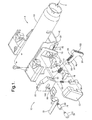
- FIG. 1 is an exploded assembly view of a first embodiment of the present invention;
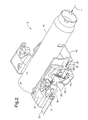
- FIG. 2 is an assembled perspective view showing the first embodiment of the present invention;
- FIG. 3 is a bottom view of a second embodiment of the present invention detailing a strap and reaction members in a minimal energy absorbing state;
- FIG. 4 is a bottom view of the second embodiment detailing the strap and reaction members fully engaged in a maximum energy absorbing state;
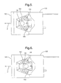
- FIG. 5 is a top view of the second embodiment detailing the load release portion at rest;
- FIG. 6 is a top view of the second embodiment detailing the load release portion having the maximum flex of the load release fingers;
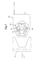
- FIG. 7 is a top view of the second embodiment detailing the energy absorbing capsule and rake bracket after the fingers have been sheared by a sufficient force.
-
- Referring to FIGS. 1 and 2, there is shown a first embodiment of an interactive
energy absorbing system 5 of the present invention in conjunction with asteering column housing 10 that moves along a collapse stroke corresponding to a force of impact by an operator which is represented by the directional force arrow F in FIG. 2. - In a collision, the vehicle body decelerates through the interaction with another body, while the operator maintains his momentum such that he is thrust against the steering hand wheel with a force of impact, again represented by the directional force arrow F. The force of impact by the operator initiates linear translation of the
steering column housing 10 in a collapse stroke that is in the direction of a centerline of thesteering column 10. Anenergy absorbing component 15 exerts a resistance force for resisting the movement of thesteering column housing 10 along the collapse stroke. Theenergy absorbing component 15 includes adeformable strap 20 engaging astationary reaction member 25 and amoveable reaction member 30. The stationary 25 and moveable 30 reaction members have an adjustable total active surface area for engaging thedeformable strap 20 and generating a resistance force. Themoveable reaction member 30 moves to adjust the total active surface area due to mechanical translation that corresponds to the force of impact by the operator. - Specifically, in the first embodiment, the
steering column housing 10 includes acolumn bracket 40 that is attached to thesteering column housing 10. Thecolumn bracket 40 includes aslot 45 formed along a length of thecolumn bracket 40 in the direction of the center line of thesteering column housing 10. Theslot 45 includesteeth 50 formed along abottom edge 55 of theslot 45. The teeth are designed to engage a tooth lock, as will be discussed in more detail below. - A
mounting bracket 60 for attaching acartridge 85 of theenergy absorbing system 5 is attached to a vehicle structure (not shown). The mounting bracket is positioned laterally with respect to thecolumn bracket 45. Abolt 70 is received within theslot 45 of thecolumn bracket 40. Thebolt 70 includes atooth lock 75 formed on an end of thebolt 70. Thetooth lock 75 includesteeth 80 that are shaped to engage theteeth 50 formed on themounting bracket 40. Theteeth mounting bracket 40 and thetooth lock 75, preventing movement in a direction opposite of the force exerted by the operator. - The
tooth lock 75 is spaced in an initial position before an impact, from theteeth 50 of themounting bracket 45 by afrangible position member 76. Thefrangible position member 76 allows thebolt 70 andtooth lock 75 to freely translate within theslot 45 prior to an impact. As can be seen in figures 1 and 2 thefrangible member 76 engages themounting bracket 60 andtooth lock 75 for maintaining the spacing of thetooth lock 75 in relation to theteeth 50 of thecolumn bracket 45. When a force is exerted on the column housing 10 from an impact with an operator, the frangible member breaks allowing theleaf spring 77 to press thetooth lock 75 into engagement with theteeth 50 of thecolumn bracket 45. After engagement of thetooth lock 75 with theteeth 50 of thecolumn bracket 45, movement of thecolumn housing 10 along its collapse stroke is synchronized with the movement of thetooth lock 75. - Again, with reference to FIGS. 1 and 2, the interactive
energy absorbing system 5 of the first embodiment includes anenergy absorbing component 15 that comprises anenergy absorbing cartridge 85 attached to themounting bracket 60. Theenergy absorbing cartridge 85 has a bore that is sized to receive an energy absorbingload adjustor 95. Theenergy absorbing cartridge 85 also includes aslot 105 formed through thecartridge 85 corresponding to a path of thebore 90. Theslot 105 formed in the cartridge receives themoveable reaction member 30 and will be described in more detail below. - The energy absorbing
load adjustor 95 is generally a T-shaped member wherein thebase portion 91 of the T is received by thebore 90 of theenergy absorbing cartridge 85. Thebase portion 91 includesteeth 94 formed on a top surface that mesh with teeth on anengagement locking member 96. Theengagement locking member 96 engages aspring 92 that places a constant bias on theengagement locking member 96 to prevent disengagement from theteeth 94 of theenergy load adjustor 95. Thetop portion 97 of the T is positioned such that it interacts with thetooth lock 75 formed on the end of thebolt 70. Thetop portion 97 includesteeth 103 formed thereon that engage thetooth lock 75 to provide a positive lock of theenergy load adjustor 95 and thetooth lock 75. The base portion of the energy absorbingload adjustor 95 includes a slot for receiving a threadedpin 74 that comprises themoveable reaction member 30. When assembled, the threadedpin 74 is received within theslot 105 formed in theenergy absorbing cartridge 85 and screwed into the threaded bore 93 of theenergy load adjustor 95.. Thestationary reaction member 25 also comprising apin 79 is permanently secured into a threadedbore 86 formed on theenergy absorbing cartridge 85. Aflat metal strap 20 is permanently mounted to the vehicle structure at anend 22 and positioned such that it can engage both thestationary reaction member 25 and themoveable reaction member 30. - The force required to plastically deform the
flat metal strap 20 by pulling it over thereaction members steering column housing 10 in its collapse stroke. Friction between theflat metal strap 20 and thereaction members steering column housing 10 in its collapse stroke. The magnitude of the resisting forces attributable to the metal deformation and to friction depend on a number of variables, including the yield strength of the material from which themetal strap 20 is made, as well as the radius of curvature of the reaction members and the area of mutual contact between themetal strap 20 and thereaction members - The
energy absorbing cartridge 85 further includes aspring 87 positioned at an end of thebore 90. Thespring 87 engages the energy absorbingload adjustor 95 and synchronizes movement of the energy absorbing load adjustor according to the force of impact of the operator. - In operation, at the outset of linear translation of the
steering column housing 10 initiated by the impact force "F" on the steering hand wheel, thebolt 70 having thetooth lock 75 formed on an end thereof is urged in the direction of the force "F". Thefrangible member 76 breaks and allows theleaf spring 75 to bias thetooth lock 75 into engagement with theteeth 50 formed on thecolumn bracket 45. Thetooth lock 75 then engages the energy absorbingload adjustor 95 such that theteeth 80 of thetooth lock 75 engage theteeth 103 of theenergy load adjustor 95. Thetooth lock 75 is therefore engaged with the mounting bracket andenergy load adjustor 95 to cause a positive lock of the parts. Movement of thecolumn housing 10 is synchronized and causes movement of the energy absorbingload adjustor 95 in the direction of the force F. Thespring 87 contained within theenergy absorbing cartridge 85 synchronizes the movement of the energy absorbingload adjustor 95 with the force of impact by the operator. Movement of the energy absorbingload adjustor 95 in turn results in movement of themoveable reaction member 30 in relation to theflat metal strap 20. As themoveable reaction member 30 moves in the direction of the force "F", the active surface area increases, resulting in a more severe plastic deformation of themetal strap 20 across the moveable 30 and stationary 25 reaction members, as well as an increase in the friction between themetal strap 20 and thereaction members load adjustor 95, which in turn varies the active surface area for engagement with themetal strap 20. As such, the magnitude of the resistance force against translation of thesteering column housing 10 along its collapse stroke is varied in proportion to the impact force of an operator. - The interactive energy absorbing system as disclosed in the first embodiment preferably includes two
energy absorbing components 15 positioned on opposite sides of thesteering column housing 10. - With reference to FIGS. 3-7, there is shown a second embodiment of the interactive energy absorbing system of the present invention. The second embodiment includes a
steering column housing 10 such as thehousing 10 of the first embodiment and arake bracket 120 attached thereto. Therake bracket 120 is coupled to theenergy absorbing component 115. Theenergy absorbing component 115 preferably comprises anenergy absorbing capsule 125. Theenergy absorbing capsule 125 includes achannel 130 formed therein. Thechannel 130 receives an energy absorbingload adjustor 135. The energy absorbingload adjustor 135 includes aportion 145 having teeth formed thereon. An energy absorbingposition lock member 140 is received within thechannel 130 and interacts with the portion of the energy absorbingload adjustor 135 having teeth to maintain the position of the energy absorbingload adjustor 135. - With reference to FIG. 3, there is shown a bottom view of the second embodiment of the
energy absorbing capsule 125 of the present invention. As can be seen, thestationary reaction member 25 preferably comprises an integrally formedshoulder 160. Themetal strap 20 is positioned to engage theshoulder 160, as well as the energy absorbingload adjustor 135 that is fixed to a vehicle body. As with the design of the first embodiment, aspring 89 is positioned at an end of thechannel 130 and interacts with the energy absorbingload adjustor 135 to synchronize movement corresponding to the force of impact by the operator. - Again, similar to the first embodiment, the total active surface area for engaging the
deformable strap 20 is variable corresponding to a magnitude of the force of impact by an operator. - Unlike the first embodiment in which the energy absorbing
load adjustor 95 causes movement of apin 74 that comprises themoveable reaction member 30 to vary the amount of resistance force, thecapsule 125 of the second embodiment moves relative to the energy absorbingload adjustor 135 thereby varying the active surface area in contact with themetal strap 20. - With reference to FIGS. 5-7, there is shown a top view of the second embodiment detailing the engagement of the
capsule 125 with therake bracket 120. As can be seen, thecapsule 125 includes aload release portion 150 that adjusts the release force necessary to separate theenergy absorbing capsule 125 from therake bracket 120. Theload release portion 150 generally comprises a pair offingers 155 that engage the energy absorbingload adjustor 135. When the force "F" designated by the arrow in FIGS. 5-7, corresponding to the impact force of an operator is applied to therake bracket 120, thefingers 155 initially start in a rest position as is shown in FIG. 5. Thefingers 155 flex until they reach their maximum as shown in FIG. 6. Additional force applied beyond the amount necessary to reach the maximum flex of FIG. 6, results in a shearing of thefingers 155 as shown in FIG. 7, resulting in a separation of theenergy absorbing capsule 125 from therake bracket 120. Preferably, thefingers 155 are formed of plastic that is injected during a forming process of thecapsule 125. Obviously, use of varying plastic materials having different flexibilities can be utilized to vary the amount of force necessary to shear thecapsule 125 from therake bracket 120. - In operation, at the onset of linear translation of the
steering column housing 10 initiated by the impact force "F" in the direction of the arrow as seen in FIGS. 3 and 4, therake bracket 120 moves in a direction of the force "F". Movement of therake bracket 120 in turn results in movement of thecapsule 125 relative to the energy absorbingload adjustor 135 that is fixed to the vehicle. Movement of thecapsule 125 relative to the energy absorbingload adjustor 135 results in a variance of the active surface area engaging thestrap 20; thereby, varying the resistance force for resisting movement of thesteering column housing 10 along the collapse stroke. - The
rake bracket 120 continues to move thecapsule 125 in the direction of the force; thereby, increasing the resistance force until theload release portion 150 comprising the pair offingers 155 shears, as seen in FIG. 7, resulting in a separation of therake bracket 120 from theenergy absorbing capsule 125. The kinetic energy of the operator has, therefore, been converted into work, and a resistance force proportional to the impact force of the operator has been generated. - While preferred embodiments are disclosed, a worker in this art would understand that various modifications would come within the scope of the invention. Thus, the following claims should be studied to determine the true scope and content of this invention.
Claims (25)
- An interactive energy absorbing system comprising:a steering column housing (10) moveable along a collapse stroke corresponding to a force of impact by an operator;an energy absorbing component (15) exerting a resistance force for resisting movement of the steering column housing (10) along the collapse stroke, the energy absorbing component (15) including a deformable strap (20) engaging a stationary reaction member (25) and a moveable reaction member (30), the stationary and moveable reaction members having an adjustable total active surface area for engaging the deformable strap (20) and generating the resistance force;the moveable reaction member (30) moving to adjust the total active surface area corresponding to the force of impact by the operator whereby the resistance force varies according to a magnitude of the force of impact thereby optimizing the performance of the energy absorbing system.
- The interactive energy absorbing system of Claim 1 wherein the steering column housing (10) includes a column bracket (40) attached thereto, the column bracket having a slot (45) formed therein.
- The interactive energy absorbing system of Claim 2 wherein the slot (45) includes teeth (50) formed on a bottom edge (55).
- The interactive energy absorbing system of Claim 2 further including a mounting bracket (60) attached to a vehicle structure, the mounting bracket (60) positioned laterally with respect to the column bracket (40).
- The interactive energy absorbing system of Claim 2 further including a bolt (70) received within the slot (45) of the column bracket (40), the bolt (70) including a tooth lock (75) formed on at least one end.
- The interactive energy absorbing system of Claim 5 wherein the tooth lock (75) includes teeth (80) formed thereon, the teeth (80) of the tooth lock (75) formed to engage the teeth (50) of the mounting bracket (60).
- The interactive energy absorbing system of Claim 1 wherein the energy absorbing component (15) comprises an energy absorbing cartridge (85) having a bore (90) formed therein, the bore receiving an energy absorbing load adjustor (95).
- The interactive energy absorbing system of Claim 7 wherein the energy absorbing load adjustor (95) further includes teeth (100) formed thereon for engaging the tooth lock (75).
- The interactive energy absorbing system of Claim 7 wherein the moveable reaction member (30) is attached to the energy absorbing load adjustor (95).
- The interactive energy absorbing system of Claim 7 wherein the energy absorbing cartridge (85) further includes a slot (105) formed therethrough corresponding to a path of the bore, the slot receiving the moveable reaction member (30).
- The interactive energy absorbing system of Claim 7 wherein the energy absorbing cartridge (85) further includes a spring (87) positioned at an end of the bore (90), the spring (87) engaging the energy absorbing load adjustor (95) for synchronizing the movement of the energy absorbing load adjustor (95) according to the force of impact of the operator.
- The interactive energy absorbing system of Claim 1 wherein the interactive energy absorbing system includes two energy absorbing components (15) positioned on opposite sides of the steering column housing (10).
- The interactive energy absorbing system of Claim 1 wherein the steering column housing (10) includes a rake bracket (120) attached thereto.
- The interactive energy absorbing system of Claim 13 wherein the rake bracket (120) is coupled to the energy absorbing component (15).
- The interactive energy absorbing system of Claim 14 wherein the energy absorbing component (15) comprises an energy absorbing capsule (125).
- The interactive energy absorbing system of Claim 15 wherein the energy absorbing capsule (125) includes a channel (130) formed therein, the channel (130) receiving an energy absorbing load adjustor (135).
- The interactive energy absorbing system of Claim 15 further including an energy absorbing position lock member (140) for maintaining the position of the energy absorbing load adjustor (135).
- The interactive energy absorbing system of Claim 16 wherein the energy absorbing load adjustor (135) is fixed to a vehicle body.
- The interactive energy absorbing system of Claim 17 wherein the energy absorbing load adjustor (135) includes a portion (145) having teeth formed thereon for engaging the energy absorbing position lock member (140).
- The interactive energy absorbing system of Claim 15 wherein the energy absorbing capsule (125) includes a load release portion (150) for adjusting the release force necessary to separate the energy absorbing capsule (125) from the rake bracket (120).
- The interactive energy absorbing system of Claim 20 wherein the load release portion (150) comprises a pair of fingers (155) that engage the energy absorbing load adjustor (135), the fingers (155) flexing until a sufficient force is applied to shear the fingers and allow separation of the energy absorbing capsule (125) from the rake bracket (120).
- The interactive energy absorbing system of Claim 15 wherein the energy absorbing capsule (125) includes an integrally formed shoulder comprising the stationary reaction member (25).
- The interactive energy absorbing system of Claim 15 further including a spring (89) positioned at an end of the channel (130), the spring (89) engaging the energy absorbing load adjustor (135) for synchronizing movement of the capsule (125) relative to the energy absorbing load adjustor (135) according to the force of impact of the operator.
- An interactive energy absorbing system comprising:a steering column housing (10) moveable along a collapse stroke corresponding to a force of impact by an operator;an energy absorbing cartridge (85) exerting a resistance force for resisting movement of the steering column housing (10) along the collapse stroke, the energy absorbing cartridge (85) having a bore (90) formed therein, the bore (90) receiving an energy absorbing load adjustor (95);a deformable strap (20) engaging a stationary reaction member (25) and a moveable reaction member (30), the stationary and moveable reaction members having an adjustable total active surface area for engaging the deformable strap (20) and generating the resistance force;the moveable reaction member (30) coupled to the energy absorbing load adjustor (95) for adjusting the total active surface area corresponding to the force of impact by the operator whereby the resistance force is optimized for a given operator according to a magnitude of the force of impact by the operator.
- An interactive energy absorbing system comprising:a steering column housing (10) moveable along a collapse stroke corresponding to a force of impact by an operator, the steering column housing having a rake bracket (120) attached thereto;an energy absorbing capsule (125) exerting a resistance force for resisting movement of the steering column housing (10) along the collapse stroke, the energy absorbing capsule (125) attached to the rake bracket (120), the energy absorbing capsule (125) having a channel (130) formed therein, the channel (130) receiving an energy absorbing load adjustor (135) that is fixed to a vehicle body;a deformable strap (20) engaging a stationary reaction member (25) and a moveable reaction member (30), the stationary and moveable reaction members having an adjustable total active surface area for engaging the deformable strap (20) and generating the resistance force;the moveable reaction member (30) adjusting the total active surface area according to movement of the capsule (125) relative to the energy absorbing load adjustor (135) the movement corresponding to the force of impact by the operator whereby the resistance force is optimized for a given operator according to a magnitude of the force of impact by the operator.
Applications Claiming Priority (2)
| Application Number | Priority Date | Filing Date | Title |
|---|---|---|---|
| US10/165,115 US6799486B2 (en) | 2002-06-07 | 2002-06-07 | Interactive energy absorbing system |
| US165115 | 2002-06-07 |
Publications (2)
| Publication Number | Publication Date |
|---|---|
| EP1369336A1 true EP1369336A1 (en) | 2003-12-10 |
| EP1369336B1 EP1369336B1 (en) | 2007-04-18 |
Family
ID=29549365
Family Applications (1)
| Application Number | Title | Priority Date | Filing Date |
|---|---|---|---|
| EP03076615A Expired - Lifetime EP1369336B1 (en) | 2002-06-07 | 2003-05-26 | Interactive energy absorbing system for a steering column of a motor vehicle |
Country Status (3)
| Country | Link |
|---|---|
| US (1) | US6799486B2 (en) |
| EP (1) | EP1369336B1 (en) |
| DE (1) | DE60313246T2 (en) |
Cited By (1)
| Publication number | Priority date | Publication date | Assignee | Title |
|---|---|---|---|---|
| CN102865989A (en) * | 2012-09-06 | 2013-01-09 | 浙江吉利汽车研究院有限公司杭州分公司 | Alignment aids for vehicle columnar crash tests |
Families Citing this family (22)
| Publication number | Priority date | Publication date | Assignee | Title |
|---|---|---|---|---|
| WO2003035450A1 (en) * | 2001-10-23 | 2003-05-01 | Trw Lucas Varity Electric Steering Limited | A vehicle steering assembly |
| US7255366B2 (en) * | 2003-01-31 | 2007-08-14 | Delphi Technologies, Inc. | Steering column assembly |
| US7407190B2 (en) | 2003-01-31 | 2008-08-05 | Delphi Technologies, Inc. | Steering column assembly |
| US6802536B2 (en) * | 2003-02-24 | 2004-10-12 | Delphi Technologies, Inc. | Adaptive energy absorbing device for a steering column |
| FR2857322B1 (en) * | 2003-07-10 | 2006-08-11 | Nacam | INFINITELY MODULAR ENERGY ABSORPTION DEVICE OF A MOTOR VEHICLE STEERING COLUMN |
| KR100510416B1 (en) * | 2003-09-06 | 2005-08-26 | 현대모비스 주식회사 | Energy absorbing tilting steering column for a vehicle |
| US7178834B2 (en) * | 2004-05-06 | 2007-02-20 | Delphi Technologies, Inc. | Adaptive release capsule for steering column |
| US7229097B2 (en) * | 2005-01-18 | 2007-06-12 | Delphi Technologies, Inc. | Snap-in capsule for steering columns |
| US7228755B2 (en) * | 2005-03-31 | 2007-06-12 | Delphi Technologies, Inc. | Release capsule for steering column |
| US20070245845A1 (en) * | 2006-04-20 | 2007-10-25 | Ridgway Jason R | Steering column assembly for a vehicle |
| US20080238070A1 (en) * | 2007-03-29 | 2008-10-02 | Bodtker Joen C | Shear capsule for steering column assembly |
| FR2915950B1 (en) * | 2007-05-11 | 2009-07-03 | Zf Systemes De Direction Nacam Sas | DEVICE FOR HOLDING IN THE ENERGY ABSORPTION POSITION OF A STEERING COLUMN OF A MOTOR VEHICLE |
| US20090090210A1 (en) * | 2007-10-05 | 2009-04-09 | Delphi Technologies, Inc. | Collapsible steering column assembly |
| GB2469678A (en) * | 2009-04-24 | 2010-10-27 | Nsk Steering Sys Europ Ltd | Collapsible steering column assembly |
| JP5230527B2 (en) * | 2009-05-27 | 2013-07-10 | 富士機工株式会社 | Steering column device |
| DE102010021956A1 (en) * | 2009-05-29 | 2011-02-17 | GM Global Technology Operations, Inc., Detroit | An energy absorbing device for a collapsible steering column assembly |
| US8376404B2 (en) * | 2010-11-23 | 2013-02-19 | Steering Solutions Ip Holding Corporation | Integrated tooth rake lock for steering column |
| US9428215B1 (en) * | 2015-03-31 | 2016-08-30 | Jtekt Corporation | Steering system |
| CN106541984B (en) * | 2015-09-18 | 2019-09-20 | 北汽福田汽车股份有限公司 | The energy-absorbing component of steering column and vehicle with it |
| GB201705272D0 (en) * | 2016-07-07 | 2017-05-17 | Trw Steering Systems Poland Sp Z O O | A steering column assembly |
| GB2612382B (en) * | 2021-10-27 | 2025-02-12 | Zf Steering Systems Poland Sp Z O O | A Steering Column Assembly |
| CN115447658B (en) * | 2022-10-24 | 2023-07-25 | 浙江极氪智能科技有限公司 | Steering column and vehicle for vehicles |
Citations (5)
| Publication number | Priority date | Publication date | Assignee | Title |
|---|---|---|---|---|
| US3392599A (en) | 1966-12-30 | 1968-07-16 | Gen Motors Corp | Energy absorbing device |
| US4886295A (en) | 1988-12-05 | 1989-12-12 | General Motors Corporation | Vehicle occupant protection system |
| US6062100A (en) * | 1998-12-17 | 2000-05-16 | General Motors Corporation | Connection for energy absorbing steering column |
| EP1093990A2 (en) * | 1999-09-20 | 2001-04-25 | Delphi Technologies, Inc. | Vehicle steering column |
| US6322103B1 (en) * | 1999-06-11 | 2001-11-27 | Delphi Technologies, Inc. | Energy absorber for motor vehicle steering column |
Family Cites Families (20)
| Publication number | Priority date | Publication date | Assignee | Title |
|---|---|---|---|---|
| US5390956A (en) * | 1994-05-17 | 1995-02-21 | Chrysler Corporation | Steering column assembly |
| US5497675A (en) | 1994-06-06 | 1996-03-12 | Chrysler Corporation | Energy absorber for a steering column |
| GB2291840A (en) * | 1994-07-29 | 1996-02-07 | Torrington Co | Vehicle steering column reach adjustment and energy absorbing mechanism |
| EP0769445B1 (en) | 1995-10-17 | 1999-01-20 | General Motors Corporation | Energy absorbing steering column for motor vehicle |
| US5605352A (en) | 1995-12-08 | 1997-02-25 | General Motors Corporation | Energy absorbing steering column |
| US5706704A (en) | 1996-03-25 | 1998-01-13 | General Motors Corporation | Energy absorbing steering column for motor vehicle |
| US5669634A (en) | 1996-05-13 | 1997-09-23 | General Motors Corporation | Energy absorber for motor vehicle steering column |
| US5720496A (en) | 1996-06-17 | 1998-02-24 | General Motors Corporation | Energy absorber for motor vehicle steering column |
| US5755461A (en) | 1997-02-11 | 1998-05-26 | Chrysler Corporation | Energy absorbing device for a steering column |
| US5803496A (en) | 1997-03-31 | 1998-09-08 | General Motors Corporation | Energy-absorbing steering column for motor vehicle |
| US5954363A (en) | 1997-12-18 | 1999-09-21 | General Motors Corporation | Energy-absorbing steering column for motor vehicle |
| FR2775646B1 (en) | 1998-03-03 | 2000-05-12 | Lemforder Nacam Sa | DUAL WIND ENERGY ABSORPTION DEVICE FOR STEERING COLUMN OF MOTOR VEHICLE |
| DE19812179C1 (en) | 1998-03-19 | 1999-08-19 | Daimler Chrysler Ag | Vehicle steering column assembly to absorb impact energy on a collision |
| GB2344078B (en) | 1998-11-24 | 2002-03-13 | Nastech Europ Ltd | Collapsible steering column for a vehicle |
| US6099038A (en) * | 1999-01-19 | 2000-08-08 | Daimlerchrysler Corporation | Upper and lower mounting bracket assembly for a steering column of an automotive vehicle |
| US6170873B1 (en) * | 1999-03-29 | 2001-01-09 | Daimlerchrysler Corporation | Steering column mounting bracket with pull loops |
| US6659504B2 (en) * | 2001-05-18 | 2003-12-09 | Delphi Technologies, Inc. | Steering column for a vehicle |
| US6592148B2 (en) * | 2001-07-03 | 2003-07-15 | Delphi Technologies, Inc. | Steering column lower bracket |
| US6655716B2 (en) * | 2001-08-28 | 2003-12-02 | Delphi Technologies, Inc. | Kinetic energy absorber |
| US6575497B1 (en) * | 2001-11-30 | 2003-06-10 | Delphi Technologies, Inc. | Reactive energy absorbing system |
-
2002
- 2002-06-07 US US10/165,115 patent/US6799486B2/en not_active Expired - Fee Related
-
2003
- 2003-05-26 DE DE60313246T patent/DE60313246T2/en not_active Expired - Lifetime
- 2003-05-26 EP EP03076615A patent/EP1369336B1/en not_active Expired - Lifetime
Patent Citations (5)
| Publication number | Priority date | Publication date | Assignee | Title |
|---|---|---|---|---|
| US3392599A (en) | 1966-12-30 | 1968-07-16 | Gen Motors Corp | Energy absorbing device |
| US4886295A (en) | 1988-12-05 | 1989-12-12 | General Motors Corporation | Vehicle occupant protection system |
| US6062100A (en) * | 1998-12-17 | 2000-05-16 | General Motors Corporation | Connection for energy absorbing steering column |
| US6322103B1 (en) * | 1999-06-11 | 2001-11-27 | Delphi Technologies, Inc. | Energy absorber for motor vehicle steering column |
| EP1093990A2 (en) * | 1999-09-20 | 2001-04-25 | Delphi Technologies, Inc. | Vehicle steering column |
Cited By (4)
| Publication number | Priority date | Publication date | Assignee | Title |
|---|---|---|---|---|
| CN102865989A (en) * | 2012-09-06 | 2013-01-09 | 浙江吉利汽车研究院有限公司杭州分公司 | Alignment aids for vehicle columnar crash tests |
| CN102865989B (en) * | 2012-09-06 | 2016-05-25 | 浙江吉利汽车研究院有限公司杭州分公司 | Alignment aids for vehicle columnar crash tests |
| CN105910789A (en) * | 2012-09-06 | 2016-08-31 | 浙江吉利汽车研究院有限公司杭州分公司 | Centering auxiliary device for vehicle column crash test |
| CN105910789B (en) * | 2012-09-06 | 2018-09-04 | 浙江吉利汽车研究院有限公司杭州分公司 | Centering auxiliary device for vehicle column crash test |
Also Published As
| Publication number | Publication date |
|---|---|
| US6799486B2 (en) | 2004-10-05 |
| EP1369336B1 (en) | 2007-04-18 |
| DE60313246D1 (en) | 2007-05-31 |
| DE60313246T2 (en) | 2007-12-20 |
| US20030226417A1 (en) | 2003-12-11 |
Similar Documents
| Publication | Publication Date | Title |
|---|---|---|
| US6799486B2 (en) | Interactive energy absorbing system | |
| EP2151366B1 (en) | Steering column having an actuator for applying a resultant force | |
| US6767057B2 (en) | Vehicle anchorage system for child seat | |
| US7455320B2 (en) | Shock absorbing steering apparatus | |
| US10759465B2 (en) | Steering column for a motor vehicle | |
| EP1094240B1 (en) | Energy absorbing shear strip bender | |
| EP3519276B1 (en) | Steering assembly with positive lock and energy absorption and pyrotechnic actuator | |
| US6322103B1 (en) | Energy absorber for motor vehicle steering column | |
| EP1438223B1 (en) | A vehicle steering assembly | |
| EP1544075B1 (en) | Vehicle impact absorption type steering column device | |
| US8585089B2 (en) | Steering column support apparatus and assembly method | |
| US20050012318A1 (en) | Load limiting structure for vehicle occupant restraint system | |
| EP2569203B1 (en) | Regulating method for an energy absorber | |
| CN100455469C (en) | Shock-absorbing steering device | |
| US20200172148A1 (en) | Steering column for a motor vehicle | |
| CN105121235A (en) | Locking apparatus, vehicle safety belt adjustment apparatus, and vehicle safety belt | |
| JPH03153441A (en) | Tensioning means for vehicular safety belt control device | |
| US20030071451A1 (en) | Responsive E/A system for steering columns | |
| EP1375297B1 (en) | Active steering column energy absorbing device | |
| US7118131B2 (en) | Adaptive energy absorber | |
| US4861071A (en) | Anchoring device for seat belt | |
| US5609365A (en) | Energy absorbing apparatus for a motor vehicle | |
| JP2022548443A (en) | Steering column anti-rotation device | |
| WO2009082304A1 (en) | A force limiting arrangement | |
| JP2012131302A (en) | Support device for steering column and method of assembling the same |
Legal Events
| Date | Code | Title | Description |
|---|---|---|---|
| PUAI | Public reference made under article 153(3) epc to a published international application that has entered the european phase |
Free format text: ORIGINAL CODE: 0009012 |
|
| AK | Designated contracting states |
Kind code of ref document: A1 Designated state(s): AT BE BG CH CY CZ DE DK EE ES FI FR GB GR HU IE IT LI LU MC NL PT RO SE SI SK TR |
|
| AX | Request for extension of the european patent |
Extension state: AL LT LV MK |
|
| 17P | Request for examination filed |
Effective date: 20040611 |
|
| AKX | Designation fees paid |
Designated state(s): DE FR GB IT |
|
| 17Q | First examination report despatched |
Effective date: 20050606 |
|
| GRAP | Despatch of communication of intention to grant a patent |
Free format text: ORIGINAL CODE: EPIDOSNIGR1 |
|
| GRAS | Grant fee paid |
Free format text: ORIGINAL CODE: EPIDOSNIGR3 |
|
| GRAA | (expected) grant |
Free format text: ORIGINAL CODE: 0009210 |
|
| AK | Designated contracting states |
Kind code of ref document: B1 Designated state(s): DE FR GB IT |
|
| REF | Corresponds to: |
Ref document number: 60313246 Country of ref document: DE Date of ref document: 20070531 Kind code of ref document: P |
|
| ET | Fr: translation filed | ||
| PLBE | No opposition filed within time limit |
Free format text: ORIGINAL CODE: 0009261 |
|
| STAA | Information on the status of an ep patent application or granted ep patent |
Free format text: STATUS: NO OPPOSITION FILED WITHIN TIME LIMIT |
|
| 26N | No opposition filed |
Effective date: 20080121 |
|
| GBPC | Gb: european patent ceased through non-payment of renewal fee |
Effective date: 20070718 |
|
| PG25 | Lapsed in a contracting state [announced via postgrant information from national office to epo] |
Ref country code: IT Free format text: LAPSE BECAUSE OF FAILURE TO SUBMIT A TRANSLATION OF THE DESCRIPTION OR TO PAY THE FEE WITHIN THE PRESCRIBED TIME-LIMIT Effective date: 20070418 |
|
| PG25 | Lapsed in a contracting state [announced via postgrant information from national office to epo] |
Ref country code: GB Free format text: LAPSE BECAUSE OF NON-PAYMENT OF DUE FEES Effective date: 20070718 |
|
| PGFP | Annual fee paid to national office [announced via postgrant information from national office to epo] |
Ref country code: FR Payment date: 20100525 Year of fee payment: 8 |
|
| REG | Reference to a national code |
Ref country code: FR Ref legal event code: TP |
|
| REG | Reference to a national code |
Ref country code: DE Ref legal event code: R081 Ref document number: 60313246 Country of ref document: DE Owner name: GM GLOBAL TECHNOLOGY OPERATIONS LLC (N. D. GES, US Free format text: FORMER OWNER: DELPHI TECHNOLOGIES, INC., TROY, US Effective date: 20110412 Ref country code: DE Ref legal event code: R081 Ref document number: 60313246 Country of ref document: DE Owner name: STEERING SOLUTIONS IP HOLDING CORP., US Free format text: FORMER OWNER: DELPHI TECHNOLOGIES, INC., TROY, US Effective date: 20110412 Ref country code: DE Ref legal event code: R081 Ref document number: 60313246 Country of ref document: DE Owner name: STEERING SOLUTIONS IP HOLDING CORP., SAGINAW, US Free format text: FORMER OWNER: DELPHI TECHNOLOGIES, INC., TROY, MICH., US Effective date: 20110412 Ref country code: DE Ref legal event code: R081 Ref document number: 60313246 Country of ref document: DE Owner name: GM GLOBAL TECHNOLOGY OPERATIONS LLC (N. D. GES, US Free format text: FORMER OWNER: DELPHI TECHNOLOGIES, INC., TROY, MICH., US Effective date: 20110412 |
|
| REG | Reference to a national code |
Ref country code: FR Ref legal event code: ST Effective date: 20120131 |
|
| PG25 | Lapsed in a contracting state [announced via postgrant information from national office to epo] |
Ref country code: FR Free format text: LAPSE BECAUSE OF NON-PAYMENT OF DUE FEES Effective date: 20110531 |
|
| PGFP | Annual fee paid to national office [announced via postgrant information from national office to epo] |
Ref country code: DE Payment date: 20120529 Year of fee payment: 10 |
|
| REG | Reference to a national code |
Ref country code: DE Ref legal event code: R082 Ref document number: 60313246 Country of ref document: DE Representative=s name: MANITZ, FINSTERWALD & PARTNER GBR, DE |
|
| REG | Reference to a national code |
Ref country code: DE Ref legal event code: R081 Ref document number: 60313246 Country of ref document: DE Owner name: STEERING SOLUTIONS IP HOLDING CORP., US Free format text: FORMER OWNER: GM GLOBAL TECHNOLOGY OPERATIONS, INC., DETROIT, US Effective date: 20121019 Ref country code: DE Ref legal event code: R081 Ref document number: 60313246 Country of ref document: DE Owner name: GM GLOBAL TECHNOLOGY OPERATIONS LLC (N. D. GES, US Free format text: FORMER OWNER: GM GLOBAL TECHNOLOGY OPERATIONS, INC., DETROIT, US Effective date: 20121019 Ref country code: DE Ref legal event code: R082 Ref document number: 60313246 Country of ref document: DE Representative=s name: MANITZ, FINSTERWALD & PARTNER GBR, DE Effective date: 20121019 Ref country code: DE Ref legal event code: R081 Ref document number: 60313246 Country of ref document: DE Owner name: GM GLOBAL TECHNOLOGY OPERATIONS LLC (N. D. GES, US Free format text: FORMER OWNER: GM GLOBAL TECHNOLOGY OPERATIONS, INC., DETROIT, MICH., US Effective date: 20121019 Ref country code: DE Ref legal event code: R081 Ref document number: 60313246 Country of ref document: DE Owner name: STEERING SOLUTIONS IP HOLDING CORP., SAGINAW, US Free format text: FORMER OWNER: GM GLOBAL TECHNOLOGY OPERATIONS, INC., DETROIT, MICH., US Effective date: 20121019 |
|
| REG | Reference to a national code |
Ref country code: DE Ref legal event code: R082 Ref document number: 60313246 Country of ref document: DE Representative=s name: MANITZ, FINSTERWALD & PARTNER GBR, DE |
|
| REG | Reference to a national code |
Ref country code: DE Ref legal event code: R081 Ref document number: 60313246 Country of ref document: DE Owner name: STEERING SOLUTIONS IP HOLDING CORP., US Free format text: FORMER OWNER: GM GLOBAL TECHNOLOGY OPERATIONS LLC (N. D. GES. D. STAATES DELAWARE), DETROIT, US Effective date: 20130313 Ref country code: DE Ref legal event code: R082 Ref document number: 60313246 Country of ref document: DE Representative=s name: MANITZ, FINSTERWALD & PARTNER GBR, DE Effective date: 20130313 Ref country code: DE Ref legal event code: R081 Ref document number: 60313246 Country of ref document: DE Owner name: GM GLOBAL TECHNOLOGY OPERATIONS LLC (N. D. GES, US Free format text: FORMER OWNER: GM GLOBAL TECHNOLOGY OPERATIONS LLC (N. D. GES. D. STAATES DELAWARE), DETROIT, US Effective date: 20130313 Ref country code: DE Ref legal event code: R081 Ref document number: 60313246 Country of ref document: DE Owner name: STEERING SOLUTIONS IP HOLDING CORP., SAGINAW, US Free format text: FORMER OWNER: GM GLOBAL TECHNOLOGY OPERATIONS LLC (N. D. GES. D. STAATES DELAWARE), DETROIT, MICH., US Effective date: 20130313 Ref country code: DE Ref legal event code: R081 Ref document number: 60313246 Country of ref document: DE Owner name: GM GLOBAL TECHNOLOGY OPERATIONS LLC (N. D. GES, US Free format text: FORMER OWNER: GM GLOBAL TECHNOLOGY OPERATIONS LLC (N. D. GES. D. STAATES DELAWARE), DETROIT, MICH., US Effective date: 20130313 |
|
| PG25 | Lapsed in a contracting state [announced via postgrant information from national office to epo] |
Ref country code: DE Free format text: LAPSE BECAUSE OF NON-PAYMENT OF DUE FEES Effective date: 20131203 |
|
| REG | Reference to a national code |
Ref country code: DE Ref legal event code: R119 Ref document number: 60313246 Country of ref document: DE Effective date: 20131203 |