EP1368738B1 - Bus system comprising an address/data bus which can be operated in a multiplex mode and control bus responding to a station by allocating a logical channel - Google Patents
Bus system comprising an address/data bus which can be operated in a multiplex mode and control bus responding to a station by allocating a logical channel Download PDFInfo
- Publication number
- EP1368738B1 EP1368738B1 EP02714018A EP02714018A EP1368738B1 EP 1368738 B1 EP1368738 B1 EP 1368738B1 EP 02714018 A EP02714018 A EP 02714018A EP 02714018 A EP02714018 A EP 02714018A EP 1368738 B1 EP1368738 B1 EP 1368738B1
- Authority
- EP
- European Patent Office
- Prior art keywords
- bus
- station
- data bus
- logical channel
- data
- Prior art date
- Legal status (The legal status is an assumption and is not a legal conclusion. Google has not performed a legal analysis and makes no representation as to the accuracy of the status listed.)
- Expired - Lifetime
Links
Images
Classifications
-
- G—PHYSICS
- G06—COMPUTING; CALCULATING OR COUNTING
- G06F—ELECTRIC DIGITAL DATA PROCESSING
- G06F13/00—Interconnection of, or transfer of information or other signals between, memories, input/output devices or central processing units
- G06F13/38—Information transfer, e.g. on bus
- G06F13/42—Bus transfer protocol, e.g. handshake; Synchronisation
- G06F13/4204—Bus transfer protocol, e.g. handshake; Synchronisation on a parallel bus
- G06F13/4208—Bus transfer protocol, e.g. handshake; Synchronisation on a parallel bus being a system bus, e.g. VME bus, Futurebus, Multibus
- G06F13/4217—Bus transfer protocol, e.g. handshake; Synchronisation on a parallel bus being a system bus, e.g. VME bus, Futurebus, Multibus with synchronous protocol
Definitions
- the invention relates to a data bus arrangement with a in Multiplexed operable data bus and a method for Operating this arrangement according to claims 1 and 2.
- Commonly used are two data bus arrangements. The one is composed of a data bus and an address bus. Above the address bus is from the control station, which in the further "Master” is called, a receiving station, in the further Called “slave”, called and then between those one or more data exchanged over the data bus.
- Such an arrangement has the disadvantage that both a data bus and an address bus is to be provided, the must have many lines according to the bit width.
- the document US4713805 shows a method for selecting a station from a Number of stations.
- a master station sends a request to a group of Stations.
- a station with transmission requirements then transmits data on one Multiplexed connection in a timeslot whose delay depends on the address of the Station depends.
- the invention is therefore based on the object, a data bus arrangement with a multiplex bus, in which the multiplexing is simplified.
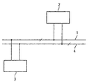
- the figure shows an inventive embodiment of the data bus arrangement.
- a data bus 1 is shown, which is not a has designated bit width.
- On this data bus 1 is also a "master” called control station 2 connected.
- Also on the data bus 1 is also called a “slave” Receiving station 3 connected.
- the bit width the data bus 1 and the addressable address space, several “slaves” not shown here be connected to the data bus 1.
- the "master” 2 Before shipping or retrieving data via the data bus 1 by the "master” 2, the "master” 2 sends an address via the data bus 1.
- the data bus 1 is constantly connected by the connected “slaves” 3 checked and as soon as the own address on the data bus 1 appears, the respective "slave” 3 feels addressed.
- a control bus 4 is additionally provided, on which both the "Master” 2 and the “Slave” 3 are connected.
- the "slave” 3 monitors the control bus 4 and is addressed as soon as this logically assigned to him Channel is open.
- control bus 4 from a line, so can two logical Be assigned to channels.
- control bus consists of two lines, d. H. two bit width, so four logical channels, etc. can be built. However, this does not mean that only so many "slaves" 3 can be connected to the data bus arrangement, such as logical channels are provided. Additional “slaves" 3 are only accessible via the address.
- this means to switch logical channels must with a predetermined number of clock periods Addresses are transmitted via the data bus 1. That means, for example, there are three “slaves" 3 on the data bus array connected and only two logical channels are available, so can according to a fixed default convention a certain number of clock periods by calling the corresponding address the "slave” 3, the previously a certain logical channel is assigned, this will be deprived and another "slave” 3.
Abstract
Description
Die Erfindung betrifft eine Datenbusanordnung mit einem im
Multiplexbetrieb betreibbaren Datenbus und ein Verfahren zum
Betreiben dieser Anordnung gemäß den Patentansprüchen 1 und
2. Allgemein üblich sind zwei Datenbusanordnungen. Die eine
ist aus einem Datenbus und einem Adreßbus zusammengesetzt.
Über dem Adreßbus wird von der Steuerstation, die im weiteren
"Master" genannt wird, eine Empfangsstation, die im weiteren
"Slave" genannt wird, aufgerufen und sodann wird zwischen denen
über den Datenbus ein Datum oder mehrere Daten ausgetauscht.
Eine derartige Anordnung weist den Nachteil auf, daß
sowohl ein Datenbus als auch ein Adreßbus vorzusehen ist, die
entsprechend der Bit-Breite viele Leitungen aufweisen müssen.The invention relates to a data bus arrangement with a in
Multiplexed operable data bus and a method for
Operating this arrangement according to
Weiterhin sind Datenbusanordnungen bekannt, die im Multiplexbetrieb betrieben werden. Dabei wird über den Datenbus vom "Master" zunächst die Adresse des "Slave" übertragen, der angesprochen werden soll. Anschließend werden dann die Daten ausgetauscht. Dies erfordert einen ziemlichen Aufwand, insbesondere wenn "Master" und "Slave" auf einem einzigen Chip liegend über den Bus miteinander verbunden sind.Furthermore, data bus arrangements are known which are multiplexed operate. This is done via the data bus from "Master" first transmit the address of the "slave", which is addressed shall be. Then the data will be replaced. This requires quite a lot of effort, especially if "master" and "slave" on a single chip lying across the bus.
Das Dokument US4713805 zeigt ein Verfahren zur Auswahl einer Station aus einer Anzahl von Stationen. Eine Masterstation sendet eine Anfrage an eine Gruppe von Stationen. Eine Station mit Übertragungsbedarf überträgt daraufhin Daten auf einer Multiplexverbindung in einem Zeitschlitz, dessen Verzögerung von der Adresse der Station abhängt.The document US4713805 shows a method for selecting a station from a Number of stations. A master station sends a request to a group of Stations. A station with transmission requirements then transmits data on one Multiplexed connection in a timeslot whose delay depends on the address of the Station depends.
Der Erfindung liegt somit die Aufgabe zugrunde, eine Datenbusanordnung
mit einem im Multiplex betreibbaren Datenbus vorzusehen,
bei dem der Multiplexbetrieb vereinfacht ist. Diese
Aufgabe wird erfindungsgemäß mit den im Patentanspruch 1 bzw.
2 angegebenen Mitteln und Maßnahmen gelöst.The invention is therefore based on the object, a data bus arrangement
with a multiplex bus,
in which the multiplexing is simplified. These
The object is achieved with the in
Durch das Vorsehen eines Steuerbusses ist es möglich, nach der Übertragung oder zusammen mit der Übertragung einer Adresse im Multiplexbetrieb über den Steuerbus dem angesprochenen "Slave" einen logischen Kanal zuzuweisen. Dieser logische Kanal bleibt sodann so lange zugewiesen, bis vom "Ma-ster" einem anderen "Slave" dieser logische Kanal zugewiesen wird. Solange der logische Kanal zugewiesen ist, muß vor dem Datenaustausch nicht erst die Adresse des anzusprechenden "Slave" aufgerufen werden, sondern es muß nur der logische Kanal geöffnet sein. Auf diese Weise wird mit geringem Aufwand der Multiplexbetrieb eingeschränkt. Diese Maßnahme lohnt sich natürlich nur so lange, wie der Steuerbus zum Ansprechen des logischen Kanals eine eingeschränkte Breite aufweist, da sonst auf den Multiplexbetrieb vollständig verzichtet werden könnte und mit Adreß- und Datenbus gearbeitet werden kann. Insgesamt bietet diese Anordnung jedoch den Vorteil, daß durch das grundsätzliche Vorsehen des Multiplexbetriebs von Adreß- und Datenübertragung ein sehr umfangreicher Adreßraum ansprechbar ist, und durch das zusätzliche Vorsehen des Steuerbusses mit eingeschränkter Bit-Breite zwischen ausgesuchten "Slaves" schnell umgeschaltet werden kann, wobei nicht von vornherein festgelegt ist, welche diese ausgesuchten "Slaves" sind. Weitere vorteilhafte Ausgestaltungen der Erfindung sind in den Unteransprüchen angegeben.By providing a control bus, it is possible to the transfer or together with the transfer of a Address in multiplex mode via the control bus to the addressed Assign a logical channel to "slave". This logical Channel remains assigned until the "Master" assigned to another "slave" this logical channel becomes. As long as the logical channel is assigned, before the Data exchange not only the address of the addressed "Slave" are called, but it must be only the logical one Channel be open. In this way, with little effort the multiplex operation restricted. This measure is worthwhile of course only as long as the control bus to respond of the logical channel has a limited width, since otherwise the multiplex operation is completely dispensed with could and can be worked with address and data bus. Overall, however, this arrangement has the advantage that by basically providing the multiplexing of Address and data transfer a very extensive address space addressable, and by the additional provision of the control bus with limited bit width between selected ones "Slaves" can be switched quickly, not by It is determined in advance which of these selected "slaves" are. Further advantageous embodiments of the invention are specified in the dependent claims.
Die Figur ein erfindungsgemäßes Ausführungsbeispiel der Datenbusanordnung.The figure shows an inventive embodiment of the data bus arrangement.
In der Figur ist ein Datenbus 1 dargestellt, der eine nicht
näher bezeichnete Bit-Breite aufweist. An diesem Datenbus 1
ist eine auch "Master" genannte Steuerstation 2 angeschlossen.
Ebenfalls ist an dem Datenbus 1 eine auch "Slave" genannte
Empfangsstation 3 angeschlossen. Entsprechend der Bit-Breite
des Datenbusses 1 und dem damit ansprechbaren Adreßraum,
können mehrere hier nicht weitere dargestellte "Slaves"
an den Datenbus 1 angeschlossen werden. Vor dem Versenden
bzw. Abrufen von Daten über den Datenbus 1 durch den "Master"
2, schickt der "Master" 2 eine Adresse über den Datenbus 1.
Der Datenbus 1 wird von den angeschlossenen "Slaves" 3 ständig
überprüft und sobald die eigene Adresse auf dem Datenbus
1 erscheint, fühlt sich der jeweilige "Slave" 3 angesprochen. In the figure, a
Sodann wird über den Datenbus nach vorgegebener üblicher Konvention Befehle und/oder Daten ausgetauscht. Es kann sich hierbei beispielsweise um einen Schreibbefehl und zu schreibende Daten von "Master" 2 an den "Slave" 3 handeln. Genauso gut kann es sich um einen Lesebefehl des "Masters" 2 an den "Slave" 3 handeln. Da die "Slaves" 3 den Datenbus ständig überwachen, muß normalerweise vor jedem Datenaustausch, d. h. Befehl und Datum, die Adresse des angesprochenen "Slaves" 3 vom "Master" 2 abgegeben werden, damit der anzusprechende "Slave" identifizierbar ist.Then, via the data bus according to a given conventional convention Commands and / or data exchanged. It may be for example, a write command and write Data from "master" 2 to the "slave" 3 act. Just like that well it can be a read command of the "Masters" 2 to the "Slave" 3 act. Since the "slaves" 3 the data bus constantly normally must be checked before each data exchange, i. H. Command and date, the address of the addressed "slave" 3 from the "Master" 2 are submitted, so that to be addressed "Slave" is identifiable.
Nunmehr ist erfindungsgemäß zusätzlich ein Steuerbus'4 vorgesehen,
an dem sowohl der "Master" 2 als auch der "Slave" 3
angeschlossen sind. Für den Betrieb bedeutet dies, daß der
"Master" 2 zunächst über den Datenbus 1 die Adresse überträgt,
so daß der "Slave" 3 angesprochen ist. Danach erfolgt
ein Zuweisungsbefehl, mit dem dem zuvor angesprochenen "Slave"
3 ein bestimmter logischer Kanal zugewiesen wird. Ist
diese Zuweisung einmal getroffen, muß vor dem nächsten Ansprechen
des ausgesuchten "Slaves" 3 durch den "Master" 2
nicht erst die Adresse über den Datenbus 1 übertragen werden,
sondern es reicht, den logischen Kanal über den Datenbus 4 zu
übermitteln. Der "Slave" 3 überwacht den Steuerbus 4 und ist
angesprochen, sobald mit diesem der ihm logisch zugewiesene
Kanal geöffnet ist.Now, according to the invention, a control bus 4 is additionally provided,
on which both the "Master" 2 and the "Slave" 3
are connected. For the operation, this means that the
"Master" 2 initially transmits the address via the
Besteht der Steuerbus 4 aus einer Leitung, so können zwei logische Kanäle zugewiesen werden.If the control bus 4 from a line, so can two logical Be assigned to channels.
Besteht der Steuerbus aus zwei Leitungen, d. h. zwei Bit-Breite, so können vier logische Kanäle usw. aufgebaut werden. Dies bedeutet allerdings nicht, daß nur so viele "Slaves" 3 an der Datenbusanordnung anschließbar sind, wie logische Kanäle vorgesehen sind. Darüber hinausgehende "Slaves" 3 sind nur über die Adresse ansprechbar. If the control bus consists of two lines, d. H. two bit width, so four logical channels, etc. can be built. However, this does not mean that only so many "slaves" 3 can be connected to the data bus arrangement, such as logical channels are provided. Additional "slaves" 3 are only accessible via the address.
Sollen alles "Slaves" 3 stets über den Steuerbus ansprechbar sein, so muß die Bit-Breite des Steurbusses so gewählt sein, daß ausreichend viele logische Kanäle adressierbar sind. Jeder "Slave" bekommt beim Adressieren einen logischen Kanal zugewiesen, der so lange gültig ist, bis diesem Kanal eine andere Adresse und damit ein anderer "Slave" zugewiesen wird.Should all "slaves" 3 always be addressed via the control bus be, so the bit width of the wheel busses must be chosen so that a sufficient number of logical channels are addressable. Everyone "Slave" gets a logical channel when addressing assigned, which is valid until this channel one another address and thus another "slave" is assigned.
Im Betrieb bedeutet das, um logische Kanäle wechseln zu können,
muß mit einer vorgegebenen Anzahl von Taktperioden
Adressen über den Datenbus 1 übertragen werden. Das bedeutet,
sind beispielsweise drei "Slaves" 3 an der Datenbusanordnung
angeschlossen und es stehen nur zwei logische Kanäle zur Verfügung,
so kann nach einer fest vorgegebenen Konvention nach
einer bestimmten Anzahl von Taktperioden durch Aufruf der
entsprechenden Adresse dem "Slave" 3, dem bisher ein bestimmter
logischer Kanal zugewiesen ist, dieser entzogen werden
und einem anderen "Slave" 3 zugewiesen werden.In operation, this means to switch logical channels,
must with a predetermined number of clock periods
Addresses are transmitted via the
Dies erhöht die Flexibilität mit geringerem Aufwand und ermöglicht es, daß bei stark eingeschränktem Multiplexbetrieb ein zügiger Datenaustausch zwischen "Master" 2 und "Slave" 3 durchführbar ist. This increases flexibility with less effort and allows it, that with very limited multiplexing a fast data exchange between "Master" 2 and "Slave" 3 is feasible.
- 11
- Datenbusbus
- 22
- Steuerstationcontrol station
- 33
- Empfangsstationreceiving station
- 44
- Steuerbuscontrol bus
Claims (3)
- Data bus arrangement having a data bus (1) which can be operated in multiplex mode and to which at least one control station (2) and a reception station (3) are connected,
characterized by
an additional control bus (4) via which the control station (2) can allocate a logical channel to the reception station (3) and data can be interchanged between control station (2) and reception station (3) for as long as the logical channel remains allocated to the reception station and is called. - Method for operating an arrangement according to Patent Claim 1, in which the control station (2) solicits a reception station (3) by transferring an address onto the data bus (1),a logical channel is allocated to the reception station (3) via the control bus (4), anddata can be interchanged between control station and reception station (3) for as long as the logical channel remains allocated to the reception station and is called.
- Method according to Claim 2,
characterized in that,
before or at the same time as the transfer of data, the reception station (3) is solicited via the control bus (4) by calling the logical channel.
Applications Claiming Priority (3)
| Application Number | Priority Date | Filing Date | Title |
|---|---|---|---|
| DE10112541A DE10112541A1 (en) | 2001-03-15 | 2001-03-15 | Databus device has databus operated in multiplex mode for transfer of data between control station and reception station |
| DE10112541 | 2001-03-15 | ||
| PCT/DE2002/000549 WO2002075551A2 (en) | 2001-03-15 | 2002-02-15 | Bus system comprising an address/data bus which can be operated in a multiplex mode and control bus responding to a station by allocating a logical channel |
Publications (2)
| Publication Number | Publication Date |
|---|---|
| EP1368738A2 EP1368738A2 (en) | 2003-12-10 |
| EP1368738B1 true EP1368738B1 (en) | 2005-06-08 |
Family
ID=7677614
Family Applications (1)
| Application Number | Title | Priority Date | Filing Date |
|---|---|---|---|
| EP02714018A Expired - Lifetime EP1368738B1 (en) | 2001-03-15 | 2002-02-15 | Bus system comprising an address/data bus which can be operated in a multiplex mode and control bus responding to a station by allocating a logical channel |
Country Status (5)
| Country | Link |
|---|---|
| US (1) | US7599383B2 (en) |
| EP (1) | EP1368738B1 (en) |
| AT (1) | ATE297569T1 (en) |
| DE (2) | DE10112541A1 (en) |
| WO (1) | WO2002075551A2 (en) |
Families Citing this family (2)
| Publication number | Priority date | Publication date | Assignee | Title |
|---|---|---|---|---|
| US7979766B2 (en) | 2004-09-08 | 2011-07-12 | Centre For Development Of Telematics | Architecture for a message bus |
| JP4601488B2 (en) * | 2005-05-12 | 2010-12-22 | 三菱電機株式会社 | Power system supervisory control system |
Family Cites Families (14)
| Publication number | Priority date | Publication date | Assignee | Title |
|---|---|---|---|---|
| FR2552609B1 (en) * | 1983-09-27 | 1985-10-25 | Cit Alcatel | METHOD AND DEVICE FOR SELECTING A STATION FROM A SET OF STATIONS DIALOGUING WITH A MAIN STATION |
| DE3585579D1 (en) * | 1984-08-23 | 1992-04-16 | Siemens Ag | DATA TRANSFER METHOD OVER A MULTIPROCESSOR BUS. |
| US4677616A (en) * | 1985-09-11 | 1987-06-30 | At&T Company | Flow control scheme for a switching network |
| US5425022A (en) * | 1989-06-16 | 1995-06-13 | British Telecommunications Public Limited Company | Data switching nodes |
| FR2648647B1 (en) * | 1989-06-19 | 1991-08-23 | Alcatel Business Systems | ARBITRATION METHOD AND DEVICE FOR TRANSMISSION ACCESS TO THE TRANSMISSION MEDIUM OF A DISTRIBUTED SWITCHING NETWORK |
| JP2789479B2 (en) * | 1989-08-14 | 1998-08-20 | 松下電器産業株式会社 | Processing device and multiprocessor system |
| FR2686991A1 (en) * | 1992-02-05 | 1993-07-30 | Sextant Avionique | METHOD, SYSTEM AND PROCESSOR FOR COMMUNICATING BETWEEN A PLURALITY OF SUBASSEMBLIES OF EQUIPMENT |
| US6442168B1 (en) * | 1997-09-17 | 2002-08-27 | Sony Corporation | High speed bus structure in a multi-port bridge for a local area network |
| JPH11275219A (en) * | 1998-03-20 | 1999-10-08 | Fujitsu Ltd | Channel reservation control system, calling side channel reservation controller, called side channel reservation controller and channel reservation control method |
| US6804229B2 (en) * | 1998-12-30 | 2004-10-12 | Nortel Networks Limited | Multiple node network architecture |
| US6674853B1 (en) * | 2000-11-22 | 2004-01-06 | Avaya Technology Corp. | Integration of remote access and service |
| FR2837296B1 (en) * | 2002-03-15 | 2004-06-25 | Airbus France | DEVICE AND METHOD FOR ACQUIRING MEASUREMENTS USING A DIGITAL COMMUNICATION BUS, USED IN PARTICULAR DURING TESTS OF AN AIRCRAFT |
| US7315551B2 (en) * | 2002-03-15 | 2008-01-01 | Lockheed Martin Corporation | Synchronous low voltage differential I/O buss |
| US7356627B2 (en) * | 2003-07-10 | 2008-04-08 | Nokia Corporation | Device identification |
-
2001
- 2001-03-15 DE DE10112541A patent/DE10112541A1/en not_active Ceased
-
2002
- 2002-02-15 DE DE50203340T patent/DE50203340D1/en not_active Expired - Lifetime
- 2002-02-15 AT AT02714018T patent/ATE297569T1/en not_active IP Right Cessation
- 2002-02-15 WO PCT/DE2002/000549 patent/WO2002075551A2/en not_active Application Discontinuation
- 2002-02-15 EP EP02714018A patent/EP1368738B1/en not_active Expired - Lifetime
-
2003
- 2003-09-15 US US10/662,794 patent/US7599383B2/en not_active Expired - Fee Related
Also Published As
| Publication number | Publication date |
|---|---|
| US7599383B2 (en) | 2009-10-06 |
| DE50203340D1 (en) | 2005-07-14 |
| WO2002075551A2 (en) | 2002-09-26 |
| ATE297569T1 (en) | 2005-06-15 |
| DE10112541A1 (en) | 2002-09-26 |
| WO2002075551A3 (en) | 2003-08-28 |
| US20040073729A1 (en) | 2004-04-15 |
| EP1368738A2 (en) | 2003-12-10 |
Similar Documents
| Publication | Publication Date | Title |
|---|---|---|
| DE3424866C2 (en) | Method and arrangement for the transmission of data, in particular in an aircraft | |
| DE2313724C3 (en) | Electronic data processing system with a number of data devices that communicate with a common controller according to the sub-calculation principle | |
| EP1309920B1 (en) | Address assignment method for at least one bus device that has recently been connected to a bus system | |
| DE3300260C2 (en) | ||
| DE10147445A1 (en) | Method and device for transmitting information on a bus system and bus system | |
| DE3049774C2 (en) | ||
| DE3300263A1 (en) | CIRCUIT ARRANGEMENT FOR ALLOCATING ACCESS TO A REQUIRED COLLECTION LINE | |
| DE19614237C1 (en) | Communication system with a master station and at least one slave station | |
| EP0739509B1 (en) | Arrangement with master and slave units | |
| DE602004008712T2 (en) | A memory bandwidth control device | |
| DE102004041823B4 (en) | Communication module with a communication interface element and communication interface element | |
| EP1368738B1 (en) | Bus system comprising an address/data bus which can be operated in a multiplex mode and control bus responding to a station by allocating a logical channel | |
| EP0175095B1 (en) | Process for transmitting data via a multiprocessor bus | |
| DE4213792A1 (en) | Operation of data transmission system for program memory control etc. - transmitting data as sequence with blocks for different subscribers and with input response telegram over common bus | |
| DE19703721C2 (en) | Method for assigning addresses to similar modules in a communication system | |
| WO2000003325A2 (en) | Can module | |
| DE102009044936A1 (en) | Procedure for exchanging data | |
| EP2156621B1 (en) | Method for operating a communication system, coordination node in a communication system and communication system | |
| DE19923327C2 (en) | Method for serial transmission of digital data | |
| EP1495376B1 (en) | Method for configuring and/or operating an automation device | |
| DE1774041B2 (en) | DATA PROCESSING SYSTEM WITH A DEVICE FOR TRANSPARENT TRANSPARENT OF DATA | |
| DE3900348C2 (en) | ||
| EP1248987A2 (en) | Multi master bus system | |
| DE19618821B4 (en) | Method for multifunctional addressing of the process data of subscribers of serial bus systems | |
| DD281039B5 (en) | METHOD AND ARRANGEMENT FOR THE BUS AWARD OF DATA PROCESSING DEVICES |
Legal Events
| Date | Code | Title | Description |
|---|---|---|---|
| PUAI | Public reference made under article 153(3) epc to a published international application that has entered the european phase |
Free format text: ORIGINAL CODE: 0009012 |
|
| 17P | Request for examination filed |
Effective date: 20030725 |
|
| AK | Designated contracting states |
Kind code of ref document: A2 Designated state(s): AT BE CH CY DE DK ES FI FR GB GR IE IT LI LU MC NL PT SE TR |
|
| RIN1 | Information on inventor provided before grant (corrected) |
Inventor name: SEDLAK, HOLGER Inventor name: KNIFFLER, OLIVER |
|
| 17Q | First examination report despatched |
Effective date: 20040803 |
|
| GRAP | Despatch of communication of intention to grant a patent |
Free format text: ORIGINAL CODE: EPIDOSNIGR1 |
|
| RBV | Designated contracting states (corrected) |
Designated state(s): AT DE FR GB IT |
|
| GRAS | Grant fee paid |
Free format text: ORIGINAL CODE: EPIDOSNIGR3 |
|
| GRAA | (expected) grant |
Free format text: ORIGINAL CODE: 0009210 |
|
| AK | Designated contracting states |
Kind code of ref document: B1 Designated state(s): AT DE FR GB IT |
|
| PG25 | Lapsed in a contracting state [announced via postgrant information from national office to epo] |
Ref country code: IT Free format text: LAPSE BECAUSE OF FAILURE TO SUBMIT A TRANSLATION OF THE DESCRIPTION OR TO PAY THE FEE WITHIN THE PRESCRIBED TIME-LIMIT;WARNING: LAPSES OF ITALIAN PATENTS WITH EFFECTIVE DATE BEFORE 2007 MAY HAVE OCCURRED AT ANY TIME BEFORE 2007. THE CORRECT EFFECTIVE DATE MAY BE DIFFERENT FROM THE ONE RECORDED. Effective date: 20050608 Ref country code: GB Free format text: LAPSE BECAUSE OF FAILURE TO SUBMIT A TRANSLATION OF THE DESCRIPTION OR TO PAY THE FEE WITHIN THE PRESCRIBED TIME-LIMIT Effective date: 20050608 |
|
| REG | Reference to a national code |
Ref country code: GB Ref legal event code: FG4D Free format text: NOT ENGLISH |
|
| REF | Corresponds to: |
Ref document number: 50203340 Country of ref document: DE Date of ref document: 20050714 Kind code of ref document: P |
|
| GBV | Gb: ep patent (uk) treated as always having been void in accordance with gb section 77(7)/1977 [no translation filed] |
Effective date: 20050608 |
|
| PG25 | Lapsed in a contracting state [announced via postgrant information from national office to epo] |
Ref country code: AT Free format text: LAPSE BECAUSE OF NON-PAYMENT OF DUE FEES Effective date: 20060215 |
|
| ET | Fr: translation filed | ||
| PLBE | No opposition filed within time limit |
Free format text: ORIGINAL CODE: 0009261 |
|
| STAA | Information on the status of an ep patent application or granted ep patent |
Free format text: STATUS: NO OPPOSITION FILED WITHIN TIME LIMIT |
|
| 26N | No opposition filed |
Effective date: 20060309 |
|
| REG | Reference to a national code |
Ref country code: FR Ref legal event code: PLFP Year of fee payment: 15 |
|
| REG | Reference to a national code |
Ref country code: FR Ref legal event code: PLFP Year of fee payment: 16 |
|
| PGFP | Annual fee paid to national office [announced via postgrant information from national office to epo] |
Ref country code: FR Payment date: 20170217 Year of fee payment: 16 |
|
| PGFP | Annual fee paid to national office [announced via postgrant information from national office to epo] |
Ref country code: DE Payment date: 20170425 Year of fee payment: 16 |
|
| REG | Reference to a national code |
Ref country code: DE Ref legal event code: R119 Ref document number: 50203340 Country of ref document: DE |
|
| REG | Reference to a national code |
Ref country code: FR Ref legal event code: ST Effective date: 20181031 |
|
| PG25 | Lapsed in a contracting state [announced via postgrant information from national office to epo] |
Ref country code: DE Free format text: LAPSE BECAUSE OF NON-PAYMENT OF DUE FEES Effective date: 20180901 |
|
| PG25 | Lapsed in a contracting state [announced via postgrant information from national office to epo] |
Ref country code: FR Free format text: LAPSE BECAUSE OF NON-PAYMENT OF DUE FEES Effective date: 20180228 |