EP1367684A1 - Overload current protection device using magnetic impedance element - Google Patents
Overload current protection device using magnetic impedance element Download PDFInfo
- Publication number
- EP1367684A1 EP1367684A1 EP02712346A EP02712346A EP1367684A1 EP 1367684 A1 EP1367684 A1 EP 1367684A1 EP 02712346 A EP02712346 A EP 02712346A EP 02712346 A EP02712346 A EP 02712346A EP 1367684 A1 EP1367684 A1 EP 1367684A1
- Authority
- EP
- European Patent Office
- Prior art keywords
- current
- power source
- magnetic
- power supply
- load
- Prior art date
- Legal status (The legal status is an assumption and is not a legal conclusion. Google has not performed a legal analysis and makes no representation as to the accuracy of the status listed.)
- Withdrawn
Links
Images


Classifications
-
- G—PHYSICS
- G01—MEASURING; TESTING
- G01R—MEASURING ELECTRIC VARIABLES; MEASURING MAGNETIC VARIABLES
- G01R33/00—Arrangements or instruments for measuring magnetic variables
- G01R33/02—Measuring direction or magnitude of magnetic fields or magnetic flux
-
- H—ELECTRICITY
- H02—GENERATION; CONVERSION OR DISTRIBUTION OF ELECTRIC POWER
- H02H—EMERGENCY PROTECTIVE CIRCUIT ARRANGEMENTS
- H02H7/00—Emergency protective circuit arrangements specially adapted for specific types of electric machines or apparatus or for sectionalised protection of cable or line systems, and effecting automatic switching in the event of an undesired change from normal working conditions
- H02H7/08—Emergency protective circuit arrangements specially adapted for specific types of electric machines or apparatus or for sectionalised protection of cable or line systems, and effecting automatic switching in the event of an undesired change from normal working conditions for dynamo-electric motors
- H02H7/085—Emergency protective circuit arrangements specially adapted for specific types of electric machines or apparatus or for sectionalised protection of cable or line systems, and effecting automatic switching in the event of an undesired change from normal working conditions for dynamo-electric motors against excessive load
Definitions
- the present invention relates to an overload current protection device for detecting a current flowing through a conductor, and cutting off the current when the current exceeds a predetermined threshold, for example, an overload current protection device capable of controlling the supply of power to a motor.
- the present invention aims at providing a low-cost and high-precision overload current protection device capable of expanding a current detection range without a constant voltage power source, etc., and without degradation in precision by an environmental characteristic such as disturbance noise, etc. and a change with time.
- an overload current protection device includes: a switch for supplying or cutting off a current from a power source to a load; a current detector for detecting the current; and a control power source which has a power supply 'transformer including primary winding and secondary winding, is inserted in the current supply line from a power source to a load, and applies power to each unit so that supply of a current to a load can be cut off when an overcurrent occurs.
- the current detector is configured by a magnetic detection element having a magnetic impedance effect, and is located in a position in which magnetic flux generated by a current flowing through the secondary winding of the power supply transformer can be detected.
- an overload current protection device includes: a switch for supplying or cutting off a multiphase current from a power source to a load; a current detector for detecting the multiphase current for each phase; and a control power source which has a power supply transformer including primary winding and secondary winding, is inserted in the current supply line from a power source to a load, and applies power to each unit so that supply of a current to a load can be cut off when an overcurrent occurs.
- each of a plurality of current detectors is configured by a magnetic detection element having a magnetic impedance effect, and is located in a position in which magnetic flux generated by a current flowing through the secondary winding can be detected.
- control power source is configured such that the primary winding and the secondary winding of the power supply transformer are hollow, and includes a capacitor for storing a current of the secondary winding, and a voltage adjuster (invention according to claim 3).
- wiring for leading the current and a substrate for fixing the wiring can be provided, wherein the magnetic detection element is arranged near the wiring on the substrate so that the magnetic flux generated by a current can be detected by a magnetic detection element (invention according to claim 4).
- two magnetic detection elements are arranged in the positions in which the absolute values of the output in response to the magnetic flux generated by a current can be equal and the polarity can be opposite to each other, and the current can be detected from the calculation result of the difference between the outputs of the two magnetic detection elements (invention according to claim 5).
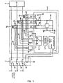
- FIG. 1 shows the entire configuration of the system showing an embodiment of the present invention.
- the contactor 2 includes contact points 2a, 2b, and 2c each of which is coupled to the motor 3 through the primary winding of respective power supply transformers 5a, 5b, and 5c by the different power supply lines.
- the contact points 2a, 2b, and 2c are mechanically coupled for simultaneous operation by an electromagnetic coil 2d.
- the electromagnetic coil 2d is connected to the end of the digital output of a microcomputer 8.
- a control circuit including the microcomputer 8, the current detectors 4a, 4b, and 4c, the power supply transformers 5a, 5b, and 5c, etc. form an electronic overload relay 1.
- the output of the current detectors 4a, 4b, and 4c is sequentially switched through a switch 6.
- the output of the current detectors 4a, 4b, and 4c selected by the switch 6 is connected to the analog input of the microcomputer 8 through a half-wave rectifier 7.
- the control power source is connected to a first capacitor C0 through rectifier diodes D0, D1, and D2 from the secondary winding of the power supply transformers 5a, 5b, and 5c, and is then formed.
- the first capacitor C0 is connected between the positive input of a voltage adjuster 9 and the ground
- a second (stabilizing) capacitor C1 is connected between the positive output of the voltage adjuster 9 and the ground so that a voltage Vcc at a constant level can be provided as a control power source from the voltage adjuster 9.
- Protective diodes D3, D4, and D5 are connected between the rectifier diodes D0, D1, and D2.
- the current detector is configured by MI elements 40a and 40b having a magnetic impedance (MI) effect, wiring 200 for leading a current, a substrate 300 for fixing the wiring 200 and the MI elements 40a and 40b, and a detection circuit 41.
- MI magnetic impedance
- the MI elements 40a and 40b can be, for example, amorphous wires as disclosed by Japanese Patent Application Laid-open No. Hei 6-281712, or thin film as disclosed by Japanese Patent Application Laid-open No. Hei 8-330645.
- FIG. 3 shows an example of the case in which currents I1 and I2 flow side by side.
- FIG. 4 shows an example of a detection circuit.
- the detection circuit 41 applies a high frequency current to the MI elements 40a and 40b using an oscillation circuit 411, and the partial pressure resistors R3 and R4, detects a change in impedance by the magnetic field of the MI elements 40a and 40b as a change in voltage using detection circuits 412a and 412b, generates the output proportional to the difference between the MI elements 40a and 40b using a differential circuit 413, and retrieves the output using an amplification circuit 414.
- the differential circuit 413 can be replaced with an addition circuit, and the output proportional to the difference between the MI elements 40a and 40b can be replaced with the output proportional to the sum of the MI elements 40a and 40b.
- the 3-phase alternating current is applied in the above-mentioned example.
- the single-phase alternating current can also be appropriately used by considering that it corresponds to one phase of the 3-phase alternating current.
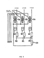
- FIG. 5 shows another example of the control power source.
- the power supply transformer is configured by an iron core.
- a hollow core is used. Since other points are the same as the example shown in FIG. 1, the explanation is omitted here.
- the current detection unit detects a current on the secondary side of the power supply transformer. Therefore, the output sensitivity can be adjusted using high sensitivity magnetic detection element. Especially when a detected current is strong, an overload current protection device having a wide current detection range without output saturation by a detected current can be provided.
- control power source according to the present invention does not require a supply of an external constant voltage power source, thereby providing a general-purpose overload current protection device capable of reducing a total cost.
- the hollow configuration of the power supply transformer of the control power source of the invention has realized a low cost overload current protection device.
Landscapes
- Physics & Mathematics (AREA)
- Condensed Matter Physics & Semiconductors (AREA)
- General Physics & Mathematics (AREA)
- Emergency Protection Circuit Devices (AREA)
- Measuring Instrument Details And Bridges, And Automatic Balancing Devices (AREA)
- Measuring Magnetic Variables (AREA)
- Hall/Mr Elements (AREA)
- Protection Of Generators And Motors (AREA)
- Rectifiers (AREA)
Abstract
Description
Claims (5)
- An overload current protection device having: a switch for supplying or cutting off a current from a power source to a load; a current detector for detecting the current; and a control power source which has a power supply transformer including primary winding and secondary winding, is inserted in the current supply line from a power source to a load, and applies power to each unit so that supply of a current to a load can be cut off when an overcurrent occurs, characterized in that
the current detector is configured by a magnetic detection element having a magnetic impedance effect, and is located in a position in which magnetic flux generated by a current flowing through the secondary winding of the power supply transformer can be detected. - An overload current protection device having: a switch for supplying or cutting off a multiphase current from a power source to a load; a current detector for detecting the multiphase current for each phase; and a control power source which has a power supply transformer including primary winding and secondary winding, is inserted in the current supply line from a power source to a load, and applies power to each unit so that supply of a current to a load can be cut off when an overcurrent occurs, characterized in that
each of a plurality of current detectors is configured by a magnetic detection element having a magnetic impedance effect, and is located in a position in which magnetic flux generated by a current flowing through the secondary winding can be detected. - The device according to claim 1 or 2, characterized in that
the control power source is configured such that the primary winding and the secondary winding of the power supply transformer are hollow, and comprises a capacitor for storing a current of the secondary winding, and a voltage adjuster. - The device according to any of claims 1 through 3, characterized in that
wiring for leading the current and a substrate for fixing the wiring can be provided, the magnetic detection element is arranged near the wiring on the substrate so that the magnetic flux generated by a current can be detected by a magnetic detection element. - The device according to any of claims 1 through 4, characterized in that
two magnetic detection elements are arranged in the positions in which the absolute values of the output in response to the magnetic flux generated by a current can be equal and the polarity can be opposite to each other, and the current can be detected from the calculation result of the difference between the outputs of the two magnetic detection elements.
Applications Claiming Priority (3)
| Application Number | Priority Date | Filing Date | Title |
|---|---|---|---|
| JP2001040266 | 2001-02-16 | ||
| JP2001040266A JP2002247751A (en) | 2001-02-16 | 2001-02-16 | Overload current protection device |
| PCT/JP2002/001238 WO2002065609A1 (en) | 2001-02-16 | 2002-02-14 | Overload current protection device using magnetic impedance element |
Publications (2)
| Publication Number | Publication Date |
|---|---|
| EP1367684A1 true EP1367684A1 (en) | 2003-12-03 |
| EP1367684A4 EP1367684A4 (en) | 2005-01-26 |
Family
ID=18902908
Family Applications (1)
| Application Number | Title | Priority Date | Filing Date |
|---|---|---|---|
| EP02712346A Withdrawn EP1367684A4 (en) | 2001-02-16 | 2002-02-14 | OVERLOAD PROTECTION AGAINST A MAGNETIC IMPEDANCE ELEMENT |
Country Status (6)
| Country | Link |
|---|---|
| US (1) | US7085116B2 (en) |
| EP (1) | EP1367684A4 (en) |
| JP (1) | JP2002247751A (en) |
| CN (1) | CN1319239C (en) |
| TW (1) | TWI255089B (en) |
| WO (1) | WO2002065609A1 (en) |
Cited By (1)
| Publication number | Priority date | Publication date | Assignee | Title |
|---|---|---|---|---|
| CN106291407A (en) * | 2016-08-01 | 2017-01-04 | 国网河北省电力公司电力科学研究院 | A kind of transformator remanent magnetism detection, elimination integrated apparatus and using method thereof |
Families Citing this family (12)
| Publication number | Priority date | Publication date | Assignee | Title |
|---|---|---|---|---|
| TWI221929B (en) | 2001-10-09 | 2004-10-11 | Fuji Electric Co Ltd | Overload current protection apparatus |
| JP3973638B2 (en) * | 2003-09-05 | 2007-09-12 | 三洋電機株式会社 | Power supply unit and power supply system having the same |
| JP4360998B2 (en) * | 2004-10-01 | 2009-11-11 | Tdk株式会社 | Current sensor |
| JP4948820B2 (en) * | 2005-11-14 | 2012-06-06 | 株式会社岡村製作所 | Shredder safety device |
| US8120334B2 (en) * | 2006-05-01 | 2012-02-21 | Texas Instruments Incorporated | System and method for phase management in a multiphase switching power supply |
| KR100850064B1 (en) | 2006-11-03 | 2008-08-04 | 동부일렉트로닉스 주식회사 | Power supply device of semiconductor device manufacturing equipment |
| US7999524B2 (en) * | 2007-06-04 | 2011-08-16 | Texas Instruments Incorporated | Interleaved power factor correction pre-regulator phase management circuitry |
| CN101834425B (en) * | 2010-03-30 | 2012-07-25 | 王有元 | Man-mobile phone-network double-communication power supply |
| US20130241456A1 (en) * | 2011-09-06 | 2013-09-19 | Andre Pierre Perra | Starter Apparatus, System, and/or Method for a Separable-Winding Motor |
| US20130235494A1 (en) * | 2011-09-06 | 2013-09-12 | Kent Jeffrey Holce | Integrated Bypass Apparatus, System, and/or Method for Variable-Frequency Drives |
| US10566881B2 (en) | 2017-01-27 | 2020-02-18 | Franklin Electric Co., Inc. | Motor drive system including removable bypass circuit and/or cooling features |
| CN108414951B (en) * | 2018-03-13 | 2023-06-30 | 武汉嘉晨电子技术有限公司 | Method and device for periodically modulating sensitivity of magnetic sensor to reduce noise of device |
Family Cites Families (15)
| Publication number | Priority date | Publication date | Assignee | Title |
|---|---|---|---|---|
| JPS4832857B1 (en) * | 1967-05-06 | 1973-10-09 | ||
| JPS5125017B2 (en) | 1971-08-31 | 1976-07-28 | ||
| US4823075A (en) * | 1987-10-13 | 1989-04-18 | General Electric Company | Current sensor using hall-effect device with feedback |
| US5448442A (en) * | 1988-06-22 | 1995-09-05 | Siemens Energy & Automation, Inc. | Motor controller with instantaneous trip protection |
| JP3272423B2 (en) | 1992-12-01 | 2002-04-08 | 科学技術振興事業団 | Method of manufacturing magnetic inductance element, magnetic inductance element, magnetic field sensor, and magnetic switch hybrid IC device |
| JPH06281712A (en) * | 1993-02-12 | 1994-10-07 | Yuzo Yoshida | Magnetic field sensor |
| JPH06347489A (en) | 1993-06-10 | 1994-12-22 | Mitsumi Electric Co Ltd | Current sensor |
| JPH0875835A (en) * | 1994-09-09 | 1996-03-22 | Mitsumi Electric Co Ltd | Magnetic impedance element and magnetic detection circuit |
| JP3091398B2 (en) * | 1995-09-14 | 2000-09-25 | 科学技術振興事業団 | Magnetic-impedance element and method of manufacturing the same |
| JP3126642B2 (en) | 1995-11-09 | 2001-01-22 | 科学技術振興事業団 | Magnetic field sensor |
| US5834940A (en) * | 1996-09-24 | 1998-11-10 | Brooks; Stanley J. | Arcing fault detector testing and demonstration system |
| JPH10232259A (en) * | 1997-02-21 | 1998-09-02 | Matsushita Electric Works Ltd | Current leakage sensor |
| JP4338789B2 (en) * | 1997-07-29 | 2009-10-07 | ユニチカ株式会社 | Magneto-impedance effect element |
| JP2000258464A (en) * | 1999-03-09 | 2000-09-22 | Mitsubishi Materials Corp | Current sensor |
| JP2002006014A (en) * | 2000-06-22 | 2002-01-09 | Fuji Electric Co Ltd | Magnetic sensor |
-
2001
- 2001-02-16 JP JP2001040266A patent/JP2002247751A/en active Pending
-
2002
- 2002-02-08 TW TW091102488A patent/TWI255089B/en not_active IP Right Cessation
- 2002-02-14 US US10/468,045 patent/US7085116B2/en not_active Expired - Fee Related
- 2002-02-14 WO PCT/JP2002/001238 patent/WO2002065609A1/en not_active Ceased
- 2002-02-14 EP EP02712346A patent/EP1367684A4/en not_active Withdrawn
- 2002-02-14 CN CNB028050444A patent/CN1319239C/en not_active Expired - Fee Related
Cited By (2)
| Publication number | Priority date | Publication date | Assignee | Title |
|---|---|---|---|---|
| CN106291407A (en) * | 2016-08-01 | 2017-01-04 | 国网河北省电力公司电力科学研究院 | A kind of transformator remanent magnetism detection, elimination integrated apparatus and using method thereof |
| CN106291407B (en) * | 2016-08-01 | 2019-03-22 | 国网河北省电力公司电力科学研究院 | A method of using an integrated device for detecting and eliminating transformer remanence |
Also Published As
| Publication number | Publication date |
|---|---|
| US7085116B2 (en) | 2006-08-01 |
| WO2002065609A1 (en) | 2002-08-22 |
| EP1367684A4 (en) | 2005-01-26 |
| CN1319239C (en) | 2007-05-30 |
| JP2002247751A (en) | 2002-08-30 |
| US20040085075A1 (en) | 2004-05-06 |
| TWI255089B (en) | 2006-05-11 |
| CN1491471A (en) | 2004-04-21 |
Similar Documents
| Publication | Publication Date | Title |
|---|---|---|
| US6984989B2 (en) | Current sensor and overload current protective device therewith | |
| US7821253B2 (en) | Direct current measuring device having magnetic sensors for current generated magnetic fields | |
| US7085116B2 (en) | Overload current protection device using magnetic impedance element | |
| US5075628A (en) | Insulation monitoring system of a direct current power supply system | |
| KR101759598B1 (en) | Digital relay with sensibility of secondary circuit opening | |
| JP3959691B2 (en) | Overload current protection device | |
| US7218494B2 (en) | Overload current protection device using magnetic impedance element | |
| US4295175A (en) | Pilot wire relay protection system for electrical distribution networks | |
| EP0633640B1 (en) | An earth leakage unit | |
| US20050030684A1 (en) | Low-voltage electronic residual current circuit breaker | |
| JP2004015961A (en) | Earth leakage breaker with three-phase open-phase protection | |
| US4135222A (en) | Fault current protection switch | |
| AU2019447727B2 (en) | Electric line (L) protection device for detecting a leakage fault, a short-circuit, fault, an overcurrent fault and an arc fault | |
| JP3221128B2 (en) | Current detector | |
| KR20180032076A (en) | Electronic motor protection relay | |
| AU2021382316B2 (en) | Electronic cut-off protection device | |
| KR101292183B1 (en) | Circuit Breaker | |
| JP2002247750A (en) | Overload current protection device | |
| KR100737061B1 (en) | Double rated current transformer circuit | |
| KR20130001410A (en) | Circuit breaker | |
| NL8002541A (en) | Earth leakage detector for AC supplies - uses current transformer and magnetically-operated switch cutting off supply when flux from two coils varies | |
| JPH04193023A (en) | Overcurrent/leakage alarm |
Legal Events
| Date | Code | Title | Description |
|---|---|---|---|
| PUAI | Public reference made under article 153(3) epc to a published international application that has entered the european phase |
Free format text: ORIGINAL CODE: 0009012 |
|
| 17P | Request for examination filed |
Effective date: 20030826 |
|
| AK | Designated contracting states |
Kind code of ref document: A1 Designated state(s): DE FR IT |
|
| A4 | Supplementary search report drawn up and despatched |
Effective date: 20041213 |
|
| RIC1 | Information provided on ipc code assigned before grant |
Ipc: 7H 02H 1/00 B Ipc: 7G 01R 33/02 B Ipc: 7H 02H 3/08 B Ipc: 7H 02H 7/085 A |
|
| 17Q | First examination report despatched |
Effective date: 20050705 |
|
| STAA | Information on the status of an ep patent application or granted ep patent |
Free format text: STATUS: THE APPLICATION HAS BEEN WITHDRAWN |
|
| 18W | Application withdrawn |
Effective date: 20090129 |