EP1367631A2 - Mass spectrometer - Google Patents
Mass spectrometer Download PDFInfo
- Publication number
- EP1367631A2 EP1367631A2 EP03011628A EP03011628A EP1367631A2 EP 1367631 A2 EP1367631 A2 EP 1367631A2 EP 03011628 A EP03011628 A EP 03011628A EP 03011628 A EP03011628 A EP 03011628A EP 1367631 A2 EP1367631 A2 EP 1367631A2
- Authority
- EP
- European Patent Office
- Prior art keywords
- ions
- ion trap
- mass spectrometer
- mass
- ion
- Prior art date
- Legal status (The legal status is an assumption and is not a legal conclusion. Google has not performed a legal analysis and makes no representation as to the accuracy of the status listed.)
- Granted
Links
Images


Classifications
-
- H—ELECTRICITY
- H01—ELECTRIC ELEMENTS
- H01J—ELECTRIC DISCHARGE TUBES OR DISCHARGE LAMPS
- H01J49/00—Particle spectrometers or separator tubes
- H01J49/26—Mass spectrometers or separator tubes
- H01J49/34—Dynamic spectrometers
- H01J49/42—Stability-of-path spectrometers, e.g. monopole, quadrupole, multipole, farvitrons
- H01J49/4205—Device types
- H01J49/424—Three-dimensional ion traps, i.e. comprising end-cap and ring electrodes
-
- H—ELECTRICITY
- H01—ELECTRIC ELEMENTS
- H01J—ELECTRIC DISCHARGE TUBES OR DISCHARGE LAMPS
- H01J49/00—Particle spectrometers or separator tubes
- H01J49/004—Combinations of spectrometers, tandem spectrometers, e.g. MS/MS, MSn
-
- H—ELECTRICITY
- H01—ELECTRIC ELEMENTS
- H01J—ELECTRIC DISCHARGE TUBES OR DISCHARGE LAMPS
- H01J49/00—Particle spectrometers or separator tubes
- H01J49/26—Mass spectrometers or separator tubes
- H01J49/34—Dynamic spectrometers
- H01J49/40—Time-of-flight spectrometers
- H01J49/401—Time-of-flight spectrometers characterised by orthogonal acceleration, e.g. focusing or selecting the ions, pusher electrode
-
- H—ELECTRICITY
- H01—ELECTRIC ELEMENTS
- H01J—ELECTRIC DISCHARGE TUBES OR DISCHARGE LAMPS
- H01J49/00—Particle spectrometers or separator tubes
- H01J49/26—Mass spectrometers or separator tubes
- H01J49/34—Dynamic spectrometers
- H01J49/42—Stability-of-path spectrometers, e.g. monopole, quadrupole, multipole, farvitrons
- H01J49/426—Methods for controlling ions
- H01J49/427—Ejection and selection methods
Definitions
- IT-TOFMS offers fast structure analysis means for this purpose.
- IT-TOFMS which is comprising two parts; an ion trap (IT) and a time-of-flight mass spectrometer (TOFMS), is expected to satisfy these requirements, because it determines a molecular structure using dissociation reactions in the ion trap and high mass resolution and a high mass accuracy mass analysis in the TOFMS.
- a 3-D quadrupole ion trap as a said IT, stores ions stably with a quadrupole high-frequency voltage. The following operation method is described in "Practical Aspects of Ion Trap Mass Spectrometry," R.E.
- Sample ions are generated outside of the ion trap and trapped inside thereof.
- the ion trap is filled with helium or other gas of several to several tens of m Torr. Incident ions are cooled by a collision with the gas and stored in the ion trap.
- the ion trap enables a removal of contaminations, a collision induced dissociation (CID) with the gas filling the ion trap, chemical reactions with the gas, or photochemical reactions.
- CID collision induced dissociation
- structure of the sample ions can be analyzed.
- Present mass spectrometers using Ion trap is incapable of sufficiently achieving a resolution and a mass accuracy necessary for a protein analysis.
- the TOFMS comprises a pusher and an ion detector.
- the pusher is an accelerator, which is composed of parallel plates and is applied high voltage pulses.
- the plates are perforated or meshed so as to enable ions to pass through them.
- the ions accelerated by the pusher fly toward the ion detector.
- a multi channel plate (or MCP) is used for the detector.
- a flying time between the pusher and the MCP is measured. Since a distance between the pusher and the MCP and kinetic energy of ions are known, the mass of ions can be calculated. Furthermore, a reflectron is often used to get a high mass resolution because it corrects a spatial and energetic spread of ions in the pusher that decreases the mass resolution.
- the above method is incapable of performing the multistage mass spectrometry and therefore structure analysis is difficult.
- the following two conventional IT-TOFMS methods are well known as those with a combination of the ion trap and the TOF mass spectrometer.
- One is a coaxial-accelerator analyzer, which is well known in the literature, R.W. Purves and Liang Li: J. Am. Soc. Spectrom. 8 (1997), page 1,085 to page 1,093.
- the ion trap operates as a pusher as well as a trapping device. In other words, ions are accelerated by applying an voltage between two endcaps almost simultaneously with turning off an RF voltage applied to a ring voltage.
- the accelerated ions are ejected from a hole opened in the center of the endcap, and the ion detector located on an extension detects the ions.
- This method has an advantage that its configuration is simple. In the above method, however, the mass resolution and the mass accuracy were not good for ions having high mass numbers because of collision between the ions and the bath gas.
- an operation of ejecting ions from the ion trap and pushing TOF is a mass separation.
- light ions arrive at the pusher earlier and heavy ions arrive later.
- the pusher size is limited, there is a mass range of ions pushable at a single ion ejection.
- the mass window is substantially around 2.
- a range of mass numbers 200 to 400 or 400 to 800 is a mass range of ions analyzable at a time. Therefore, to measure ions of mass numbers 200 to 4,000, the measurement need be performed five. Although these measurements can be performed in parallel, it decreases a throughput, which significantly reduces sensitivity. Therefore, desirably the mass window is equal to or more than 20.
- the present invention discloses an operating method for ion trap TOF mass spectrometry with a wide mass window.
- the mass window problem in the prior art disclosed in Japanese Unexamined Patent Publication (Kokai) No. 2001-297730 is caused by that all ions are ejected simultaneously at the center of the ion trap.
- ions of all mass numbers can be focused at a single point on the pusher.
- ions are sequentially ejected in descending order of weight at low energy from an opening of the endcap of the ion trap, and they are accelerated.
- the heavy ions are flying in a drift region, light ions are ejected from the ion trap at a certain timing and accelerated. Thereafter, when the heavy ions arrive at the pusher, the light ions just get to arrive at the pusher.
- Figs. 1 and 5 show diagrams of the first embodiment.
- the apparatus comprises of a 3-D quadrupole ion trap (reference numerals 1 to 3 in the diagram), a drift region (5), and an orthogonal acceleration TOF mass spectrometer (6, 7, and 8).
- a 3-D quadrupole ion trap reference numerals 1 to 3 in the diagram
- a drift region (5)
- an orthogonal acceleration TOF mass spectrometer 6, 7, and 8
- the mass resolution and the mass accuracy are achieved.
- the above portions are stored in a vacuum chamber.
- An ion trap chamber and a TOF chamber are evacuated with vacuum pumps (14 and 15). Ions generated by an ion source (16) pass through an ion guide (17).
- the first embodiment is characterized in a configuration by that the acceleration region after ejecting ions is negligibly short in comparison with the drift region.
- the ejected ions are accelerated by an electrostatic voltage V acc applied between an endcap (3) and a drift region (6).
- the ions generated by the ion source are injected from an opening of an endcap 2 and stored in the ion trap. Isolation and reactions are performed in the trap. These operations are called multistage mass spectrometry (MS n ).
- the mass accuracy of generated ions is insufficient only using the ion trap as a mass spectrometer, and therefore it is preferably combined with an orthogonal acceleration time-of-flight mass spectrometer (TOFMS) capable of achieving a high mass accuracy.
- TOFMS orthogonal acceleration time-of-flight mass spectrometer
- the present invention relates to a procedure from an ion ejection from the ion trap to an execution of the mass spectrometry.
- the apparatus comprises the ion trap, the acceleration region, the drift region, and the TOF mass spectrometer. Referring to Figs. 4A-4C, there is shown a diagram for a principle of the ion ejection from the ion trap. A potential for trapping ions is shown in Fig. 4A.
- L can be decreased by decreasing t scan , thereby reducing the apparatus in size.
- t scan ⁇ 10 ms in view of the practical apparatus size.
- a resonant frequency inside the ion trap is tens to hundreds of kHz and therefore preferably t scan > 10 ms.
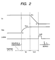
- FIG. 2 An operation procedure of the present invention is shown in Fig. 2. Ions generated by the ion source are trapped in the ion trap. After a completion of the trapping, the ion isolation, ion decomposition, and other operations are performed. Thereafter, the electrostatic voltage V ddc is applied to a portion between the endcap electrodes. In this operation, the electrostatic voltage is preferably increased to the given value V ddc , taking time of approx. 0.1 ms or longer. Otherwise, heavy ions are lost in the ion trap at this time, by which a sufficient mass window cannot be obtained problematically.
- the resonant frequency of ions in the trap is about tens to hundreds of kHz and a resonant instability of ions may occur unless the variation occurs over a period of time sufficiently longer than the period of the frequency.
- ions are stable if V ddc is increased over 0.1 ms or longer.
- the sweep time t scan is given by (Eq. 14). At the same time when the high-frequency amplitude becomes substantially zero, the pusher is activated.
- the pushed ions have kinetic energy of eV acc coaxially with the ion trap and kinetic energy of eV push in a direction perpendicular to it.
- ions reaches the MCP (8) via the reflectron (7) under these conditions.
- L TOF is given a distance between the axis on an extension of the ion trap and the reflectron and D is a distance between the center of the pusher and that of the MCP
- an ion trap size zO, an ion trap frequency, and an ion trap high-frequency amplitude are assumed to be 5 mm, 770 kHz, and 250 V, respectively.
- V ddc , V acc , and t scan are assumed 2 V, 10 V, and 500 ms, respectively, and a distance L between the ion trap endcap and the center of the pusher (a drift distance) is assumed 0.15 m.
- the He gas pressure in the ion trap is assumed to be 10-2 Torr and an assumption is made to have an elastic collision model in which a collision cross-section of the ions is in proportion to the cube of the mass number.
- the zero point of the ion arrival time shows the time when the high-frequency amplitude starts to decrease linearly. At this point, ions having high mass numbers emitted earlier arrive there.
- Fig. 9 shows an average value of the ion arrival time at each point. As shown here, ions having different mass numbers focus at a single point.
- Figs. 10A, 10B, and 10C there are shown r coordinate distributions of ions ejected from the ion trap. It is understood that 80% ions can penetrate with a hole of 2 mm ⁇ or so on the ion trap.
- Fig. 11 shows an energy distribution of ions ejected from the ion trap in the r direction in the pusher. In detection with an orthogonal acceleration TOFMS, the energy distribution in the r direction is an important factor to determine the resolution.
- the resolution it is preferable to restrain the energy to 50 meV or lower though it depends upon the TOF configuration: 80% ions are contained in it. In this simulation, all data of ions emitted from the ion trap is collected. It is possible to remove high-energy ions by making a slit in the middle. As a result of the above, it has been proved that the ions having mass numbers 200 to 4,000 can be measured in the TOF analysis with a single ejection from the ion trap.
- the ions are accelerated between the acceleration voltage and the ground voltage applied to the ion trap when they are ejected from the ion outlet of the ion trap.
- the ground electrode having a hole that the ions pass through is installed in close proximity to the opening of the ion trap. Therefore, the hole on the ion trap endcap and the hole on the ground metal plate form an electron lens. Its effect on ion focusing on the pusher depends upon conditions such as the acceleration voltage V acc and the distance from the pusher.
- each hole can be covered with fine metal mesh having a high open area ratio. It has an effect of improving the mass resolution of the TOF mass spectrometer since the electric field is shaped though the metal mesh decreases the ion transmittance.
- the ion flight region of the drift region is electrically shielded so as to prevent an accidental force from acting on ions to expand the space distribution in the pusher.
- a grounded metal tube (5) is installed. In the installation, if the inlet portion of the metal tube serves as the ground electrode of the acceleration region, the inlet is covered with fine metal mesh, thereby eliminating a lens effect caused by an electric field distortion.
- a static lens (13) is arranged between an end of the drift region and the pusher so as to narrow the space and energy distribution in the acceleration direction in the pusher.
- a quadrupole static lens capable of focusing in an arbitrary direction.
- a combination of two quadrupole static lenses is effective.
- a beam is intensively focused in the acceleration direction with a first quadrupole static lens and then it is weakly dissipated in the acceleration direction with a second quadrupole static lens, thereby intensively narrowing down the beam in the acceleration direction.
- the potential energy distribution other than in the acceleration direction expands instead, it does not affect the resolution.
- the static lens does not have any aberration caused by mass at the same ion kinetic energy and therefore it is unnecessary to change the applied voltage to the static lens corresponding to the mass of the passing ions.
- the TOF mass spectrometer is held in a higher vacuum than in the ion trap and therefore they are arranged in different vacuum chambers with a hole which ions pass through provided between them.
- a vacuum chamber wall is located at an appropriate position in the drift region.
- the vacuum chamber is formed from a metal and grounded. Therefore, it has no problem in continuity or unity with the metal tube forming the drift region.
- the vacuum chamber and the metal tube are preferably of the same metal type and they are in direct contact with each other.
- the surface material of the metal mesh spread inside and outside the ion trap at the outlet should be the same as the surface material of the ion trap.
- the mesh is plated with gold, too.
- the mesh should be formed from the same stainless material having the same composition and they are directly joined.
- Fig. 3 shows a second embodiment.
- the second embodiment is characterized by that a distance between the ion trap and the pusher is shorter than that of the first embodiment by elongating the acceleration region from the ion trap to the TOFMS.
- the application to this embodiment only requires a replacement of the distance L between the ion trap and the center of the pusher, which has been used in the analytic discussion of the principle of ejecting ions in the first embodiment, with 2L acc +L. It is assumed again here that L acc is a length of the acceleration region and that L is a distance between the outlet of the acceleration region and the center of the pusher (drift region).
- the distance between the ion trap and the TOF spectrometer can be reduced to around a half due to the coefficient 2 attached to L acc .
- Other principles and effects of the second embodiment are the same as in the first embodiment.
- a difference between the first and second embodiments in the above is an acceleration method of ions ejected from the ion trap.
- ions are accelerated immediately after the ions are ejected from the ion trap and the ions are drifted at a uniform velocity toward the pusher the distance L away.
- ions are accelerated in the acceleration region having a length of several tens of millimeters or longer immediately after the ions are ejected from the ion trap and the ions are guided to the pusher with a shorter distance for drifting.
- a multistage metal plate 305 is arranged so that the acceleration unit has a parallel electric field gradient so as to obtain a more ideal parallel electric field. Distortion, if any, spreads the ion spatial distribution, thereby decreasing the mass resolution of the TOF mass spectrometer.
- the parallel electric field is secured by covering the incidence plane and the emission plane with fine metal mesh having a high open area ratio, if necessary.
- the apparatus is designed so that the vacuum chamber wall separating the ion trap and the TOF mass spectrometer is located in a subsequent stage of the acceleration region.
- the ion trap, the acceleration region, the vacuum chamber wall and the drift region, (the quadrupole static lens, if necessary), and the pusher are arranged in this order.
- the ion trap high-frequency voltage is fixed with a gradual increase of the electrostatic voltage V ddc .
- the electrostatic voltage V ddc is applied to the extent that ions are ejected in the t dc portion in Fig. 2.
- a time function for sweeping V ddc is put in proportion to the 1/2 power of the time period from the start of the increase.
- This method involves large micromotion (a forced oscillation due to the RF) kinetic energy generated by ejecting ions at an intensive RF voltage, thereby broadening the ion energy distribution in the z direction, which results in an adverse effect on the sensitivity or the resolution. It, however, is useful to detect ions having high mass numbers ejected from the ion trap in t dc before the high-frequency amplitude decreases simultaneously with ions ejected in t scan in Fig. 2.
- Fig. 12 shows a diagram of two quadrupole ion traps arranged with the same electrode arrangement as one conventionally suggested by Reinhold et al. (PCT patent WO 01/15201A2).
- ions generated by the ion source are stored in the first ion trap (501, 502, and 503). Thereafter, the ions are moved to the second ion trap (504, 505, and 506) and then introduced into a time-of-flight mass spectrometer for a multistage mass spectrometry, as disclosed in the diagram.
- Its effective voltage application method was not described, and the transport between the ion traps has not come into practical use.
- ions of respective mass numbers are ejected in the state shown in Fig. 4A and the ions are ejected at potentials different with respect to each mass number.
- the ions have energies different with respect to each mass number and therefore a focusing optical system of the ejected ions have a large energy aberration, by which the transmittance becomes low. Therefore, in order to cause the ions to be incident on the second ion trap at a high efficiency, a high acceleration voltage is needed. The high acceleration voltage, however, decreases a trapping efficiency in the second ion trap.
- the respective ions are ejected at the same potential independently of the mass numbers and the ions can be ejected at almost the same energy from the ion trap, by which the ejected ions have almost the same energy distribution independently of the mass numbers. Accordingly, there is no chromatic aberration of the ion optical system, thereby improving the transport efficiency between the ion traps.
- ions generated by the ion source are stored in the first ion trap (501, 502, and 503) and then the ions are moved to the second ion trap (504, 505, and 506) by using the ion ejection method of the present invention.
- a mass spectrometry is performed by using the TOFMS (510).
- An electrostatic voltage for focusing the ions on the second endcap electrode hole is applied to the static lens. While the ion control is performed in the second ion trap, ions are stored in the first ion trap, thereby improving the entire ion usability. Furthermore, there is no need for spatially focusing ions having different mass numbers in the ion transport between the ion traps of this embodiment and therefore the amplitude need not be decreased linearly as in the first and second embodiments.
- the transport from the second ion trap to the TOFMS is performed in the same manner as in the methods of the first and second embodiments.
- only two ion traps are used in the diagram, it is possible to achieve the same effect of improving the transport efficiency between the ion traps according to the present invention also when installing three or more ion traps in tandem.
- ions are introduced to the Fourier transform mass spectrometer to which a magnetic field is applied, which increases the ion incidence efficiency and therefore improves the sensitivity.
- ions are accelerated to move at a finite speed inside the ion trap in which the vacuum is low and therefore ions tend to be ejected from the ion trap later than a given timing due to a collision with gas or due to a viscous drag.
- ions are not accelerated inside the ion trap in which the vacuum is high, but they are accelerated in a region in which the vacuum is low after they are ejected from the ion trap, by which this problem is resolved.
- ions in a wide mass range obtained by a protein analysis can be analyzed at a high mass accuracy with a single TOF mass spectrometry operation. This enables a fast protein structure analysis.
Abstract
Description


- 1
- Ring electrode,
- 2
- Endcap electrode (Inlet),
- 3
- Endcap electrode (Outlet),
- 4
- Helium gas inlet,
- 5
- Drift region,
- 6
- TOF pusher,
- 7
- Reflectron,
- 8
- Multichannel plate,
- 9
- High-frequency power supply for ion trap,
- 10
- DC power supply,
- 11
- DC power supply,
- 12
- DC power supply,
- 13
- Quadrupole static lens,
- 14
- Vacuum pump,
- 15
- Vacuum pump,
- 16
- Ion source,
- 301
- Ring electrode,
- 302
- Endcap electrode (Inlet),
- 303
- Endcap electrode (Outlet),
- 304
- Helium gas inlet,
- 305
- Acceleration region,
- 306
- TOF pusher,
- 307
- Reflectron,
- 308
- Multichannel plate,
- 309
- High-frequency power supply for ion trap,
- 310
- DC power supply,
- 311
- DC power supply,
- 312
- DC power supply,
- 313
- Quadrupole static lens,
- 501
- Ring electrode of the first ion trap,
- 502
- Endcap electrode of the first ion trap (Inlet),
- 503
- Endcap electrode of the first ion trap (Outlet),
- 504
- Ring electrode of the second ion trap,
- 505
- Endcap electrode of the second ion trap (Inlet),
- 506
- Endcap electrode of the second ion trap (Outlet),
- 507
- Static lens,
- 508
- Static lens,
- 509
- Ion source,
- 510
- Mass analyzer.
Claims (11)
- A mass spectrometer having a-3-D quadrupole ion trap, wherein an electrostatic voltage is applied to a portion between endcap electrodes (2, 3) in the 3-D quadrupole ion trap comprising a ring electrode (1) and a pair of endcap electrodes (2, 3) opposed to each other and further a high-frequency voltage applied to a ring electrode (1) is swept from a large amplitude to a small amplitude.
- The mass spectrometer according to claim 1, wherein the electrostatic voltage between said endcap electrodes (2, 3) is a fixed value while the high-frequency voltage is swept.
- The mass spectrometer according to claim 1, wherein in sweeping the high-frequency voltage from the large amplitude to the small amplitude the amplitude decreases linearly relative to the time.
- The mass spectrometer according to claim 1, wherein ions ejected from said ion trap are detected with a time-of-flight (TOF) mass spectrometer.
- The mass spectrometer according to claim 4, wherein said time-of-flight mass spectrometer accelerates ions in a direction of 70° to 110° relative to a track of ions from the ion trap to the time-of-flight mass spectrometer.
- The mass spectrometer according to claim 4, wherein a pusher (6) of said TOF mass spectrometer is activated at the moment an envelope of the high-frequency amplitude reaches zero in decreasingly sweeping the amplitude of the high-frequency voltage.
- The mass spectrometer according to claim 1, wherein the electrostatic voltage between said endcap electrodes (2, 3) is increased to a given value over time of 0.1 ms or longer.
- The mass spectrometer according to claim 7, wherein the electrostatic voltage is in proportion to the 1/2 power of the time period from the start of an increase of the electrostatic voltage.
- The mass spectrometer according to claim 4, wherein a drift region (5) is arranged between said 3-D quadrupole ion trap and said time-of-flight mass spectrometer.
- The mass spectrometer according to claim 4, wherein an ion acceleration region (305) is arranged between said 3-D quadrupole ion trap and said time-of-flight mass spectrometer.
- The mass spectrometer according to claim 4, wherein one or more quadrupole static lenses (13) are arranged between said 3-D quadrupole ion trap and said time-of-flight mass spectrometer.
Applications Claiming Priority (2)
| Application Number | Priority Date | Filing Date | Title |
|---|---|---|---|
| JP2002156647A JP3752470B2 (en) | 2002-05-30 | 2002-05-30 | Mass spectrometer |
| JP2002156647 | 2002-05-30 |
Publications (3)
| Publication Number | Publication Date |
|---|---|
| EP1367631A2 true EP1367631A2 (en) | 2003-12-03 |
| EP1367631A3 EP1367631A3 (en) | 2005-06-22 |
| EP1367631B1 EP1367631B1 (en) | 2008-02-13 |
Family
ID=29417215
Family Applications (1)
| Application Number | Title | Priority Date | Filing Date |
|---|---|---|---|
| EP03011628A Expired - Lifetime EP1367631B1 (en) | 2002-05-30 | 2003-05-22 | Mass spectrometer |
Country Status (4)
| Country | Link |
|---|---|
| US (1) | US6852972B2 (en) |
| EP (1) | EP1367631B1 (en) |
| JP (1) | JP3752470B2 (en) |
| DE (1) | DE60319029T2 (en) |
Cited By (8)
| Publication number | Priority date | Publication date | Assignee | Title |
|---|---|---|---|---|
| GB2395061A (en) * | 2002-08-08 | 2004-05-12 | Micromass Ltd | A mass spectrometer comprising a linear array of ion traps |
| US6794642B2 (en) | 2002-08-08 | 2004-09-21 | Micromass Uk Limited | Mass spectrometer |
| GB2400230A (en) * | 2002-08-08 | 2004-10-06 | Micromass Ltd | A mass spectrometer comprising a linear array of ion traps |
| US6875980B2 (en) | 2002-08-08 | 2005-04-05 | Micromass Uk Limited | Mass spectrometer |
| EP1648020A2 (en) * | 2001-11-22 | 2006-04-19 | Micromass UK Limited | Mass spectrometer |
| US7102126B2 (en) | 2002-08-08 | 2006-09-05 | Micromass Uk Limited | Mass spectrometer |
| EP1743354A1 (en) * | 2004-05-05 | 2007-01-17 | MDS Inc. doing business through its MDS Sciex Division | Ion guide for mass spectrometer |
| EP3249680A1 (en) * | 2016-05-26 | 2017-11-29 | Thermo Finnigan LLC | Systems and methods for reducing the kinetic energy spread of ions radially ejected from a linear ion trap |
Families Citing this family (20)
| Publication number | Priority date | Publication date | Assignee | Title |
|---|---|---|---|---|
| JP3752470B2 (en) * | 2002-05-30 | 2006-03-08 | 株式会社日立ハイテクノロジーズ | Mass spectrometer |
| JP3912345B2 (en) * | 2003-08-26 | 2007-05-09 | 株式会社島津製作所 | Mass spectrometer |
| US7084398B2 (en) * | 2004-05-05 | 2006-08-01 | Sciex Division Of Mds Inc. | Method and apparatus for selective axial ejection |
| DE102005025497B4 (en) * | 2005-06-03 | 2007-09-27 | Bruker Daltonik Gmbh | Measure light bridges with ion traps |
| US7470900B2 (en) * | 2006-01-30 | 2008-12-30 | Varian, Inc. | Compensating for field imperfections in linear ion processing apparatus |
| DE102006016896B4 (en) * | 2006-04-11 | 2009-06-10 | Bruker Daltonik Gmbh | Orthogonal Time-of-Flight Mass Spectrometer of Low Mass Discrimination |
| GB0610752D0 (en) * | 2006-06-01 | 2006-07-12 | Micromass Ltd | Mass spectrometer |
| US8013290B2 (en) * | 2006-07-31 | 2011-09-06 | Bruker Daltonik Gmbh | Method and apparatus for avoiding undesirable mass dispersion of ions in flight |
| JP4918846B2 (en) * | 2006-11-22 | 2012-04-18 | 株式会社日立製作所 | Mass spectrometer and mass spectrometry method |
| US8242438B2 (en) * | 2007-07-13 | 2012-08-14 | Thermo Finnigan Llc | Correction of time of flight separation in hybrid mass spectrometers |
| JP5262010B2 (en) * | 2007-08-01 | 2013-08-14 | 株式会社日立製作所 | Mass spectrometer and mass spectrometry method |
| JP5243977B2 (en) * | 2009-01-23 | 2013-07-24 | 日本電子株式会社 | Vertical acceleration time-of-flight mass spectrometer |
| JP5314603B2 (en) | 2010-01-15 | 2013-10-16 | 日本電子株式会社 | Time-of-flight mass spectrometer |
| DE102010001349B9 (en) * | 2010-01-28 | 2014-08-28 | Carl Zeiss Microscopy Gmbh | Device for focusing and for storing ions |
| EP2580774B1 (en) * | 2010-06-08 | 2016-10-26 | Micromass UK Limited | Mass spectrometer with beam expander |
| US8461524B2 (en) * | 2011-03-28 | 2013-06-11 | Thermo Finnigan Llc | Ion guide with improved gas dynamics and combined noise reduction device |
| JP6541210B2 (en) | 2011-12-27 | 2019-07-10 | ディーエイチ テクノロジーズ デベロップメント プライベート リミテッド | Method of extracting ions with low M / Z ratio from ion trap |
| GB201409074D0 (en) * | 2014-05-21 | 2014-07-02 | Thermo Fisher Scient Bremen | Ion ejection from a quadrupole ion trap |
| JP6237907B2 (en) | 2014-08-19 | 2017-11-29 | 株式会社島津製作所 | Time-of-flight mass spectrometer |
| CN109585258B (en) * | 2018-12-03 | 2020-05-01 | 中国科学技术大学 | Three-dimensional ion trap system and control method thereof |
Citations (2)
| Publication number | Priority date | Publication date | Assignee | Title |
|---|---|---|---|---|
| US4540884A (en) * | 1982-12-29 | 1985-09-10 | Finnigan Corporation | Method of mass analyzing a sample by use of a quadrupole ion trap |
| JP2001297730A (en) * | 2000-04-14 | 2001-10-26 | Hitachi Ltd | Mass spectrometer device |
Family Cites Families (13)
| Publication number | Priority date | Publication date | Assignee | Title |
|---|---|---|---|---|
| US5783824A (en) * | 1995-04-03 | 1998-07-21 | Hitachi, Ltd. | Ion trapping mass spectrometry apparatus |
| DE69733887D1 (en) * | 1996-05-14 | 2005-09-08 | Analytica Of Branford Inc | ION TRANSFER OF MULTIPOLION LEADERS IN MULTIPOLION LEADERS AND ION CASES |
| JP3294106B2 (en) * | 1996-05-21 | 2002-06-24 | 株式会社日立製作所 | Three-dimensional quadrupole mass spectrometry and apparatus |
| JP3624419B2 (en) * | 1996-09-13 | 2005-03-02 | 株式会社日立製作所 | Mass spectrometer |
| GB9717926D0 (en) * | 1997-08-22 | 1997-10-29 | Micromass Ltd | Methods and apparatus for tandem mass spectrometry |
| GB9802112D0 (en) * | 1998-01-30 | 1998-04-01 | Shimadzu Res Lab Europe Ltd | Method of trapping ions in an ion trapping device |
| JP3650551B2 (en) * | 1999-09-14 | 2005-05-18 | 株式会社日立製作所 | Mass spectrometer |
| US6683301B2 (en) * | 2001-01-29 | 2004-01-27 | Analytica Of Branford, Inc. | Charged particle trapping in near-surface potential wells |
| CA2391140C (en) * | 2001-06-25 | 2008-10-07 | Micromass Limited | Mass spectrometer |
| DE60217458T2 (en) * | 2001-11-22 | 2007-04-19 | Micromass Uk Ltd. | Mass spectrometer and method |
| US6777673B2 (en) * | 2001-12-28 | 2004-08-17 | Academia Sinica | Ion trap mass spectrometer |
| JP3951741B2 (en) * | 2002-02-27 | 2007-08-01 | 株式会社日立製作所 | Charge adjustment method and apparatus, and mass spectrometer |
| JP3752470B2 (en) * | 2002-05-30 | 2006-03-08 | 株式会社日立ハイテクノロジーズ | Mass spectrometer |
-
2002
- 2002-05-30 JP JP2002156647A patent/JP3752470B2/en not_active Expired - Fee Related
-
2003
- 2003-05-22 EP EP03011628A patent/EP1367631B1/en not_active Expired - Lifetime
- 2003-05-22 DE DE60319029T patent/DE60319029T2/en not_active Expired - Lifetime
- 2003-05-29 US US10/446,667 patent/US6852972B2/en not_active Expired - Fee Related
Patent Citations (2)
| Publication number | Priority date | Publication date | Assignee | Title |
|---|---|---|---|---|
| US4540884A (en) * | 1982-12-29 | 1985-09-10 | Finnigan Corporation | Method of mass analyzing a sample by use of a quadrupole ion trap |
| JP2001297730A (en) * | 2000-04-14 | 2001-10-26 | Hitachi Ltd | Mass spectrometer device |
Non-Patent Citations (4)
| Title |
|---|
| PATENT ABSTRACTS OF JAPAN vol. 2002, no. 02, 2 April 2002 (2002-04-02) & JP 2001 297730 A (HITACHI LTD), 26 October 2001 (2001-10-26) * |
| PURVES R W ET AL: "Development and Characterization of an Electrospray Ionization Ion Trap/Linear Time-of-Flight Mass Spectrometer" JOURNAL OF THE AMERICAN SOCIETY FOR MASS SPECTROMETRY, ELSEVIER SCIENCE INC, US, vol. 8, no. 10, October 1997 (1997-10), pages 1085-1093, XP004094064 ISSN: 1044-0305 * |
| TODD J F J ET AL: "Some alternative scanning methods for the ion trap mass spectrometer" INTERNATIONAL JOURNAL OF MASS SPECTROMETRY AND ION PROCESSES NETHERLANDS, vol. 106, 15 May 1991 (1991-05-15), pages 117-135, XP002325355 ISSN: 0168-1176 * |
| WOLLNIK H: "Ion optics in mass spectrometers" JOURNAL OF MASS SPECTROMETRY 1999 UNITED KINGDOM, vol. 34, no. 10, 1999, pages 991-1006, XP002322857 ISSN: 1076-5174 * |
Cited By (18)
| Publication number | Priority date | Publication date | Assignee | Title |
|---|---|---|---|---|
| EP1648020A2 (en) * | 2001-11-22 | 2006-04-19 | Micromass UK Limited | Mass spectrometer |
| EP2317539A1 (en) * | 2001-11-22 | 2011-05-04 | Micromass UK Limited | Mass spectrometer |
| EP1648020A3 (en) * | 2001-11-22 | 2008-07-02 | Micromass UK Limited | Mass spectrometer |
| GB2400230A (en) * | 2002-08-08 | 2004-10-06 | Micromass Ltd | A mass spectrometer comprising a linear array of ion traps |
| US7102126B2 (en) | 2002-08-08 | 2006-09-05 | Micromass Uk Limited | Mass spectrometer |
| GB2395063B (en) * | 2002-08-08 | 2004-10-27 | Micromass Ltd | Mass spectrometer |
| GB2400230B (en) * | 2002-08-08 | 2005-02-09 | Micromass Ltd | Mass spectrometer |
| US6875980B2 (en) | 2002-08-08 | 2005-04-05 | Micromass Uk Limited | Mass spectrometer |
| DE10336502B4 (en) * | 2002-08-08 | 2006-03-09 | Micromass Uk Ltd. | mass spectrometry |
| GB2395061B (en) * | 2002-08-08 | 2004-09-22 | Micromass Ltd | Mass spectrometer |
| GB2395061A (en) * | 2002-08-08 | 2004-05-12 | Micromass Ltd | A mass spectrometer comprising a linear array of ion traps |
| GB2395063A (en) * | 2002-08-08 | 2004-05-12 | Micromass Ltd | A mass spectrometer comprising a linear array of ion traps |
| US6794642B2 (en) | 2002-08-08 | 2004-09-21 | Micromass Uk Limited | Mass spectrometer |
| DE10336500B4 (en) * | 2002-08-08 | 2008-12-24 | Micromass Uk Ltd. | Method for mass spectrometry |
| DE10336503B4 (en) * | 2002-08-08 | 2009-12-10 | Micromass Uk Ltd. | Method for mass spectrometry |
| EP1743354A1 (en) * | 2004-05-05 | 2007-01-17 | MDS Inc. doing business through its MDS Sciex Division | Ion guide for mass spectrometer |
| EP1743354B1 (en) * | 2004-05-05 | 2019-08-21 | MDS Inc. doing business through its MDS Sciex Division | Ion guide for mass spectrometer |
| EP3249680A1 (en) * | 2016-05-26 | 2017-11-29 | Thermo Finnigan LLC | Systems and methods for reducing the kinetic energy spread of ions radially ejected from a linear ion trap |
Also Published As
| Publication number | Publication date |
|---|---|
| JP2003346706A (en) | 2003-12-05 |
| EP1367631A3 (en) | 2005-06-22 |
| US20030222214A1 (en) | 2003-12-04 |
| EP1367631B1 (en) | 2008-02-13 |
| JP3752470B2 (en) | 2006-03-08 |
| DE60319029T2 (en) | 2008-09-04 |
| US6852972B2 (en) | 2005-02-08 |
| DE60319029D1 (en) | 2008-03-27 |
Similar Documents
| Publication | Publication Date | Title |
|---|---|---|
| EP1367631B1 (en) | Mass spectrometer | |
| JP6223397B2 (en) | Mass spectral analysis method and mass spectrometer | |
| US7399962B2 (en) | All-mass MS/MS method and apparatus | |
| US9287101B2 (en) | Targeted analysis for tandem mass spectrometry | |
| EP2385543B1 (en) | Controlling ion populations in a mass analyzer | |
| US7208728B2 (en) | Mass spectrometer | |
| JP3990889B2 (en) | Mass spectrometer and measurement system using the same | |
| US5504326A (en) | Spatial-velocity correlation focusing in time-of-flight mass spectrometry | |
| CA2448990C (en) | A time-of-flight mass spectrometer for monitoring of fast processes | |
| US20170032952A1 (en) | Multi-Reflecting Time-of-Flight Mass Spectrometer with Axial Pulsed Converter | |
| EP0687381B1 (en) | Ion gun and mass spectrometer employing the same | |
| GB2477007A (en) | Electrostatic trap mass spectrometer | |
| WO2015026727A1 (en) | Ion optical system for maldi-tof mass spectrometer | |
| US20120280118A1 (en) | Method for operating a time-of-flight mass spectrometer with orthogonal ion pulsing | |
| US7019286B2 (en) | Time-of-flight mass spectrometer for monitoring of fast processes | |
| JP2015170445A (en) | Mass spectrometry apparatus and mass spectrometry method | |
| WO2019211918A1 (en) | Orthogonal acceleration time-of-flight mass spectrometer |
Legal Events
| Date | Code | Title | Description |
|---|---|---|---|
| PUAI | Public reference made under article 153(3) epc to a published international application that has entered the european phase |
Free format text: ORIGINAL CODE: 0009012 |
|
| AK | Designated contracting states |
Kind code of ref document: A2 Designated state(s): AT BE BG CH CY CZ DE DK EE ES FI FR GB GR HU IE IT LI LU MC NL PT RO SE SI SK TR |
|
| AX | Request for extension of the european patent |
Extension state: AL LT LV MK |
|
| PUAL | Search report despatched |
Free format text: ORIGINAL CODE: 0009013 |
|
| AK | Designated contracting states |
Kind code of ref document: A3 Designated state(s): AT BE BG CH CY CZ DE DK EE ES FI FR GB GR HU IE IT LI LU MC NL PT RO SE SI SK TR |
|
| AX | Request for extension of the european patent |
Extension state: AL LT LV MK |
|
| RIC1 | Information provided on ipc code assigned before grant |
Ipc: 7H 01J 49/40 A Ipc: 7H 01J 49/42 B |
|
| 17P | Request for examination filed |
Effective date: 20050713 |
|
| AKX | Designation fees paid |
Designated state(s): DE GB |
|
| GRAP | Despatch of communication of intention to grant a patent |
Free format text: ORIGINAL CODE: EPIDOSNIGR1 |
|
| GRAS | Grant fee paid |
Free format text: ORIGINAL CODE: EPIDOSNIGR3 |
|
| 17Q | First examination report despatched |
Effective date: 20060208 |
|
| GRAA | (expected) grant |
Free format text: ORIGINAL CODE: 0009210 |
|
| AK | Designated contracting states |
Kind code of ref document: B1 Designated state(s): DE GB |
|
| REG | Reference to a national code |
Ref country code: GB Ref legal event code: FG4D |
|
| REF | Corresponds to: |
Ref document number: 60319029 Country of ref document: DE Date of ref document: 20080327 Kind code of ref document: P |
|
| PLBE | No opposition filed within time limit |
Free format text: ORIGINAL CODE: 0009261 |
|
| STAA | Information on the status of an ep patent application or granted ep patent |
Free format text: STATUS: NO OPPOSITION FILED WITHIN TIME LIMIT |
|
| 26N | No opposition filed |
Effective date: 20081114 |
|
| REG | Reference to a national code |
Ref country code: DE Ref legal event code: R082 Ref document number: 60319029 Country of ref document: DE Representative=s name: STREHL SCHUEBEL-HOPF & PARTNER MBB PATENTANWAE, DE Ref country code: DE Ref legal event code: R081 Ref document number: 60319029 Country of ref document: DE Owner name: HITACHI HIGH-TECH CORPORATION, JP Free format text: FORMER OWNER: HITACHI HIGH-TECHNOLOGIES CORPORATION, TOKYO, JP |
|
| PGFP | Annual fee paid to national office [announced via postgrant information from national office to epo] |
Ref country code: DE Payment date: 20210427 Year of fee payment: 19 |
|
| PGFP | Annual fee paid to national office [announced via postgrant information from national office to epo] |
Ref country code: GB Payment date: 20210429 Year of fee payment: 19 |
|
| REG | Reference to a national code |
Ref country code: DE Ref legal event code: R119 Ref document number: 60319029 Country of ref document: DE |
|
| GBPC | Gb: european patent ceased through non-payment of renewal fee |
Effective date: 20220522 |
|
| PG25 | Lapsed in a contracting state [announced via postgrant information from national office to epo] |
Ref country code: GB Free format text: LAPSE BECAUSE OF NON-PAYMENT OF DUE FEES Effective date: 20220522 Ref country code: DE Free format text: LAPSE BECAUSE OF NON-PAYMENT OF DUE FEES Effective date: 20221201 |