EP1367610A2 - PCT composition, method of making the same, and thermistor body obtained therefrom - Google Patents
PCT composition, method of making the same, and thermistor body obtained therefrom Download PDFInfo
- Publication number
- EP1367610A2 EP1367610A2 EP03012377A EP03012377A EP1367610A2 EP 1367610 A2 EP1367610 A2 EP 1367610A2 EP 03012377 A EP03012377 A EP 03012377A EP 03012377 A EP03012377 A EP 03012377A EP 1367610 A2 EP1367610 A2 EP 1367610A2
- Authority
- EP
- European Patent Office
- Prior art keywords
- ptc
- polymer matrix
- article
- electron beam
- thermistor body
- Prior art date
- Legal status (The legal status is an assumption and is not a legal conclusion. Google has not performed a legal analysis and makes no representation as to the accuracy of the status listed.)
- Granted
Links
Images


Classifications
-
- H—ELECTRICITY
- H01—ELECTRIC ELEMENTS
- H01C—RESISTORS
- H01C17/00—Apparatus or processes specially adapted for manufacturing resistors
- H01C17/06—Apparatus or processes specially adapted for manufacturing resistors adapted for coating resistive material on a base
- H01C17/065—Apparatus or processes specially adapted for manufacturing resistors adapted for coating resistive material on a base by thick film techniques, e.g. serigraphy
- H01C17/06506—Precursor compositions therefor, e.g. pastes, inks, glass frits or green body
- H01C17/06573—Precursor compositions therefor, e.g. pastes, inks, glass frits or green body characterised by the permanent binder
- H01C17/06586—Precursor compositions therefor, e.g. pastes, inks, glass frits or green body characterised by the permanent binder composed of organic material
-
- C—CHEMISTRY; METALLURGY
- C08—ORGANIC MACROMOLECULAR COMPOUNDS; THEIR PREPARATION OR CHEMICAL WORKING-UP; COMPOSITIONS BASED THEREON
- C08K—Use of inorganic or non-macromolecular organic substances as compounding ingredients
- C08K3/00—Use of inorganic substances as compounding ingredients
- C08K3/02—Elements
- C08K3/08—Metals
-
- H—ELECTRICITY
- H01—ELECTRIC ELEMENTS
- H01C—RESISTORS
- H01C7/00—Non-adjustable resistors formed as one or more layers or coatings; Non-adjustable resistors made from powdered conducting material or powdered semi-conducting material with or without insulating material
- H01C7/02—Non-adjustable resistors formed as one or more layers or coatings; Non-adjustable resistors made from powdered conducting material or powdered semi-conducting material with or without insulating material having positive temperature coefficient
- H01C7/027—Non-adjustable resistors formed as one or more layers or coatings; Non-adjustable resistors made from powdered conducting material or powdered semi-conducting material with or without insulating material having positive temperature coefficient consisting of conducting or semi-conducting material dispersed in a non-conductive organic material
-
- C—CHEMISTRY; METALLURGY
- C08—ORGANIC MACROMOLECULAR COMPOUNDS; THEIR PREPARATION OR CHEMICAL WORKING-UP; COMPOSITIONS BASED THEREON
- C08K—Use of inorganic or non-macromolecular organic substances as compounding ingredients
- C08K3/00—Use of inorganic substances as compounding ingredients
- C08K3/02—Elements
- C08K3/08—Metals
- C08K2003/0862—Nickel
Definitions
- the present invention relates to a PTC composition, employed as a temperature sensor or an overcurrent protection device, having a positive temperature coefficient of resistivity (hereinafter simply referred to as PTC), whose ohmic value increases as temperature rises, a method of making the same, and a thermistor body obtained therefrom.
- PTC positive temperature coefficient of resistivity
- a composition in which an electrically conductive substance is dispersed into a crystalline polymer matrix has been known to exhibit a PTC behavior (see U.S. Patent Nos. 3,243,753 and 3,351,882).
- Compositions exhibiting such a behavior (hereinafter also referred to as PTC compositions when necessary) have recently been demanded to be employed in protection devices for lithium ion batteries and common circuits, such as those in cellular phones. Therefore, it is necessary for the PTC compositions to have a high heat resistance and a high stability.
- these conventional PTC compositions have been problematic in terms of their low heat resistance and storage stability.
- crosslinking method (1) chemical cross-linking by an organic peroxide, (2) aqueous crosslinking by a silane coupling agent and water, and (3) radiation crosslinking upon irradiation with an electron beam.
- the chemical crosslinking has been problematic in that, since the composition is shaped into an article having a predetermined form and then must be subjected to heat treatment at a temperature higher than the melting point of the polymer matrix included therein, the form of the article is hard to maintain, there is a possibility of the article thermally deteriorating, and so forth.
- aqueous crosslinking has been problematic in that the degree of crosslinking may vary among batches, the process takes a longer period of time since the article shaped from the composition must be immersed in hot water for a long time, substances such as organotin compounds which may affect environments must be used as a catalyst, and so forth.
- the radiation crosslinking enables crosslinking with no difference in the degree of crosslinking among batches by irradiating an article shaped from a relatively low-density PTC composition using carbon black as an electrically conductive powder.
- the heat resistance and thermal shock resistance of the article may decrease when the article is subjected to the radiation crosslinking. This seems to be because the polymer matrix contained in the composition is not uniformly crosslinked.
- a first aspect of the present invention relates to a PTC composition containing (a) a crosslinked polymer matrix having a gel fraction of at least 10%, and (b) an electrically conductive substance, wherein an article shaped therefrom yields an electric resistance of at least 50 m ⁇ at 25°C after being placed in an environment repeating 200 times of a temperature change between -40°C and +85°C, the article exhibiting no thermal deformation when placed on a hot plate at 200°C for 5 minutes.
- Another aspect of the present invention relates to a method of making a PTC composition
- a method of making a PTC composition comprising the steps of preparing an article shaped from a mixture containing a polymer matrix, an electrically conductive substance, and an organic compound having a melting point lower than that of the polymer matrix; and crosslinking the mixture by irradiating the article by a dose of 40 to 300 kGy with an electron beam having an acceleration voltage of at least 250 kV.
- Still another aspect of the present invention relates to a PTC thermistor body comprising a composition containing (a) a crosslinked polymer matrix having a gel fraction of at least 10%, and (b) an electrically conductive substance; the PTC thermistor body yielding an electric resistance of at least 50 m ⁇ at 25°C after being placed in an environment repeating 200 times of a temperature change between -40°C and +85°C, and exhibiting no thermal deformation when placed on a hot plate at 200 °C for 5 minutes.
- Still another aspect of the present invention relates to a thermistor device comprising (1) a PTC thermistor body comprising a composition containing (a) a crosslinked polymer matrix having a gel fraction of at least 10%, and (b) an electrically conductive substance; the PTC thermistor body yielding an electric resistance of at least 50 m ⁇ at 25°C after being placed in an environment repeating 200 times of a temperature change between -40°C and +85°C, and exhibiting no thermal deformation when placed on a hot plate at 200°C for 5 minutes; and (2) respective electrodes formed on both sides of the PTC thermistor body.
- the present invention can provide a thermistor device excellent in heat resistance and thermal shock resistance even when it has a high density, a PTC composition to become a material therefor, and a method of making the same.
- Fig. 1 is a schematic sectional view showing the thermistor device in accordance with an embodiment of the present invention
- Fig. 2 is a plan view of Fig. 1;
- Fig. 3 is a graph showing resistance vs. temperature (R-T) characteristics of thermistor device samples in accordance with Examples and Comparative Examples;
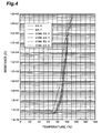
- Fig. 4 is a graph showing resistance vs. temperature (R-T) characteristics of thermistor device samples in accordance with Examples and Comparative Examples.
- Fig. 1 showing the thermistor device in accordance with an embodiment of the present invention and Fig. 2 illustrating its plan view.
- the thermistor device 2 in accordance with this embodiment comprises a thermistor body 4. Electrodes 6, 6 are formed on both sides of the thermistor body 4, respectively. External electrode terminals 8, 8 are connected to the electrodes 6, 6, respectively.
- the thermistor body 4 normally has a thickness of about 100 to 1,000 ⁇ m and a body density of at least 2.5 g/cm 3 , preferably at least 3 g/cm 3 .
- the thermistor body 4 also has a specific resistance of 1 ⁇ -cm or less, preferably not greater than 0.5 ⁇ -cm.
- the "body density” refers to a value obtained when the weight of a shaped article such as a thermistor body is divided by the volume of the article including its open pores and closed pores.
- the thermistor body 4 is constituted by a PTC composition.
- the PTC composition in accordance with the present invention contains, at least, a polymer matrix and an electrically conductive substance.
- composition refers to a product generated when a mixture is crosslinked.
- mixture refers to not only a simply kneaded product, but also a shaped article in which the kneaded product is formed into a sheet, a film, or the like, and a mode in which both sides of the shaped article are formed with electrodes.
- the polymer matrix has a gel fraction of at least 10%.
- the polymer matrix having a gel fraction of less than 10% is not fully crosslinked, thus exhibiting a poor heat resistance and a lower storage stability.
- the gel fraction is measured as follows:
- the polymer matrix have a melting point of 70°C to 200°C.
- the polymer matrix when used together with a low molecular weight organic compound, preferably has a melting point higher than that of the low molecular weight organic compound by at least 30°C, by at least 30°C but not more than 110°C in particular, in order to prevent flowage, deformation of the thermistor body 4, and the like due to melting of the low molecular weight organic compound during operation.
- the polymer matrix may be either crystalline or amorphous.
- the polymer matrix include polyolefins, e.g., polyethylene, ethylene/vinyl acetate copolymer, polyalkyl acrylates such as polyethyl acrylate, and polyalkyl (meth)acrylates such as polymethyl (meth)acrylate; halogen-containing polymers, e.g., fluorine-containing polymers such as polyvinylidene fluoride, polytetrafluoroethylene, polyhexafluoropropylene, and their copolymers, and chlorine-containing polymers such as polyvinyl chloride, polyvinylidene chloride, chlorinated polyvinyl chloride, chlorinated polyethylene, chlorinated polypropylene, and their copolymers; polystyrene; and thermoplastic elastomers.
- Polyolefins may be copolymers. Among them, polyolefins are used preferably. More preferably, linear, low-density polyethylene prepared by polymerization over a metallocene catalyst, e.g., low-density polyethylene having a density of less than 0.95 g/cm 3 is used.
- the metallocene catalyst refers to a coordinated ionic polymerization catalyst mainly using a metallocene catalyst as a transition metal compound and mainly using methylaluminoxane as an organic metal compound.
- the melt flow rate (MFR) of linear, low-density polyethylene prepared by polymerization over a metallocene catalyst is defined by ASTM-D1238.
- the MFR is preferably 4 (g/10 min) or less. When the MFR exceeds 4 (g/10 min), the melt viscosity of polymer matrix becomes too low, whereby the stability of each characteristic of the polymer matrix tends to deteriorate.
- the lower limit of the MFR is usually about 0.1 (g/10 min) .
- One kind of the polymer matrix may be used alone, or two or more kinds thereof may be used in combination.
- linear, low-density polyethylene having an MFR of 4 (g/10 min) or less prepared by polymerization over a metallocene catalyst is used alone.
- the number average molecular weight Mn of polymer matrix is preferably on the order of 10, 000 to 50, 000, more preferably on the order of 18,700 to 36,800.
- the electrically conductive substance used in the present invention has the form of electrically conductive particles with spiky protrusions.
- the electrically conductive particles with spiky protrusions are formed by primary particles each having sharp protrusions.
- Each spiky protrusion has a conical form with a height which is 1/3 to 1/50 of the particle size of the primary particle.
- a plurality of, usually about 10 to 500, spiky particles exist in one primary particle.
- the electrically conductive particles with spiky protrusions are preferably made of a metal, nickel in particular.
- electrically conductive particles may be in a powder form in which primary particles exist individually, the primary particles preferably form secondary particles each composed of about 10 to 1,000 primary particles connected in series like a chain. Those in powder and chain forms may mingle with each other as well.
- a specific example of powder-like electrically conductive particle is a nickel powder with a spherical form as a whole having spiky protrusions. This kind of nickel powder is commercially available, for example, under the product name of INCO type 123 nickel powder (manufactured by Inco Limited) . These commercially available products have an average particle size of about 3 to 7 ⁇ m, a body density of 1.8 to 2.7 g/cm 3 , and a specific surface area of about 0.34 to 0.44 m 2 /g.
- a specific example of chain-like electrically conductive particle is a filamentary nickel powder.
- This kind of nickel powder is commercially available, for example, under the product name of INCO type 210, 255, 270, and 287 nickel powder (manufactured by Inco Limited), among which INCO type 210 and 255 are preferable in particular.
- the primary particles included in the chain-like electrically conductive particles preferably have an average particle size of 0. 1 ⁇ m or greater, 0.5 to 4.0 ⁇ m in particular, most preferably 1.0 to 4.0 ⁇ m.
- 50% by weight or less of primary particles having an average particle size of at least 0.1 ⁇ m but less than 1.0 ⁇ m may be mixed with primary particles having an average particle size of 1.0 to 4 . 0 um.
- the electrically conductive particles have a body density of about 0.3 to 1.0 g/cm 3 , and a specific surface area of about 0.4 to 2.5 m2/g. The average particles size was measured by Fisher subsieve method.
- carbon type electrically conductive particles such as carbon black, graphite, carbon fiber, metal-coated carbon black, graphitized carbon black, and metal-coated carbon fiber; metal particles in the form of sphere, flake, fiber, and the like; foreign- metal-coated metal particles such as silver-coated nickel; ceramic type electrically conductive particles such as tungsten carbide, titanium nitride, zirconium nitride, titanium carbide, titanium boride, and molybdenum silicide; electrically conductive potassium titanate whiskers disclosed in Japanese Patent Application Laid-Open Nos. HEI 8-31554 and 9-27383; and the like may be added to those mentioned above.
- electrically conductive particles are contained by 25 wt% or less in electrically conductive particles having spiky protrusions.
- the PTC composition in addition to the polymer matrix, the PTC composition further contains an organic compound (hereinafter referred to as low-melting organic compound) having a melting point lower than that of the polymer matrix .
- the PTC composition is not only required to have a higher heat resistance, a higher thermal shock resistance, and a lower electric resistance, but also is demanded to provide a thermistor device operable at a lower temperature.
- the PTC composition in the present invention can easily adjust a temperature at which the ohmic value changes drastically in its resistance vs. temperature characteristic, thus making it possible to provide a thermistor device operable at a lower temperature as well.
- the organic compound used in the present invention has a molecular weight of about 1,000 or less, and is preferably a crystalline one having a molecular weight of 200 to 800. Though the organic compound can be used without any restriction as long as its melting point mp is lower than that of the above-mentioned polymer matrix, it is preferably solid at ambient temperature of about 25°C.
- low-melting organic compound examples include waxes, e.g., petroleum waxes such as paraffin wax andmicrocrystallinewax, and natural waxes such as vegetable waxes, animal waxes, and mineral waxes; fats and oils known as fats or solid fats; and crystalline resins.
- waxes e.g., petroleum waxes such as paraffin wax andmicrocrystallinewax, and natural waxes such as vegetable waxes, animal waxes, and mineral waxes; fats and oils known as fats or solid fats; and crystalline resins.
- Crystalline resins refer to resins whose melting points can be observed in thermal measurement, and are distinguished from amorphous resins whose melting points cannot be observed.
- crystalline resins include polyolefin type crystalline resins represented by the group consisting of polyethylene type crystalline resins such as linear or branched high-density polyethylene and low-density polyethylene, polypropylene type crystalline resins such as linear or branched high-density polypropylene and low-density polypropylene, polymethylpentene, polybutene, polymethylbutene, polymethylhexene, polyvinylnaphthalene, and the like; polyester type crystalline resins represented by the group consisting of polyethylene terephthalate (PET), polybutylene terephthalate (PBT), polyethylene naphthalate, aromatic polyester, and the like; polyamide type crystalline resins represented by the group consisting of nylon-6, nylon-66, nylon-12, polyamide imide, and the like; fluorine-
- an organic compound having a melting point mp of at least 40°C but less than 110°C is selected from paraffin wax, microcrystalline wax, fatty acid, fatty acid ester, fatty acid amide, fatty acid ester, fatty acid amide, crystalline resin, and the like.
- One kind of the organic compound may be used alone, or two or more kinds may be used in combination.
- the crystalline resin is preferably used as the organic compound, and ethylene homopolymer is used more preferably.
- Ethylene homopolymer has a melting point on the order of 85°C to 100°C and a density of about 0.96 g/cm 3 .
- the PTC composition may contain an antioxidant. Phenols, organosulfurs, phosphites (organophosphorus compounds), and the like are used as the antioxidant.
- the PTC composition may contain additives imparting favorable pyroconductivity thereto.
- additives include silicon nitride, silica, alumina, and clay (mica, talc, and the like) disclosed in Japanese Patent Application Laid-Open No. SHO 57-12061; silicon, silicon carbide, silicon nitride, beryllia, and selenium disclosed in Japanese Patent Publication No. HEI 7-77161; and inorganic nitrides, magnesium oxide, and the like disclosed in Japanese Patent Application Laid-Open No. HEI 5-217711.
- the PTC composition may contain, for example, inorganic solids such as titanium oxide, iron oxide, zinc oxide, silica, magnesium oxide, alumina, chromium oxide, barium sulfate, calcium carbonate, calcium hydroxide, and lead oxide disclosed in Japanese Patent Application Laid-Open No. HEI 5-226112 and barium titanate, strontium titanate, and potassium niobate each having a high relative dielectric constant disclosed in Japanese Patent Application Laid-Open No. HEI 6-68963 in order to improve the durability thereof.
- inorganic solids such as titanium oxide, iron oxide, zinc oxide, silica, magnesium oxide, alumina, chromium oxide, barium sulfate, calcium carbonate, calcium hydroxide, and lead oxide disclosed in Japanese Patent Application Laid-Open No. HEI 5-226112 and barium titanate, strontium titanate, and potassium niobate each having a high relative dielectric constant disclosed in Japanese Patent Application Laid-Open No.
- the PTC composition may contain boron carbide disclosed in Japanese Patent Application Laid-Open No. HEI 4-74383 and the like in order to improve the voltage endurance thereof.
- the PTC composition may contain alkali titanate hydrate disclosed in Japanese Patent Application Laid-Open No. HEI 5-74603; titanium oxide, iron oxide, zinc oxide, and silica disclosed in Japanese Patent Application Laid-Open No. HEI 8-17563; and the like in order to improve the strength of an article such as the PTC thermistor body 4 formed from the PTC composition.
- the PTC composition may contain alkali halide and melamine resin disclosed in Japanese Patent Publication No. SHO 59-10553; benzoic acid, dibenzylidene sorbitol, and metal benzoate disclosed in Japanese Patent Application Laid-Open No. HEI 6-76511; talc, zeolite, and dibenzylidene sorbitol disclosed in Japanese Patent Application Laid-Open No. HEI 7-6864; sorbitol derivatives (gelling agents) and asphalt disclosed in Japanese Patent Application Laid-Open No. HEI 7-263127; sodium bis(4-t-butylphenyl)phosphate; and the like as a crystalline nucleating agent.
- the PTC composition may contain alumina and magnesia hydrate disclosed in Japanese Patent Publication No. HEI 4-28744, metal hydrates and silicon carbide disclosed in Japanese Patent Application Laid-Open No. SHO 61-250058, and the like as an arc adjusting/regulating agent.
- the PTC composition may contain IRGANOX MD102 (manufactured by Ciba-Geigy Corp.) disclosed in Japanese Patent Application Laid-Open No. HEI 7-6864 and the like as a metal harm inhibitor.
- the PTC composition may contain antimony trioxide and aluminum hydroxide disclosed in Japanese Patent Application Laid-Open No. SHO 61-239581, magnesium hydroxide disclosed in Japanese Patent Application Laid-OpenNo. HEI 5-74603, and organic compounds or polymers containing a halogen such as 2,2-bis(4-hydroxy-3,5-dibromophenyl)propane, polyvinylidene fluoride (PVDF), phosphorus-containing compounds such as aluminum phosphate, and the like as a flame retardant.
- a halogen such as 2,2-bis(4-hydroxy-3,5-dibromophenyl)propane, polyvinylidene fluoride (PVDF), phosphorus-containing compounds such as aluminum phosphate, and the like as a flame retardant.
- the PTC composition may contain zincsulfide, alkaline magnesium carbonate, aluminum oxide, calcium silicate,magnesium silicate, aluminosilicate clay (kaolinite, montmorillonite, and the like), glass powder, glass flake, glass fiber, calcium sulfate, and the like.
- the electrode 6 is constituted by a metal foil containing Ni, or the like.
- the electrode 6 usually has a thickness of 25 to 35 ⁇ m.
- the external electrode terminal 8 is made of a material containing Ni.
- the external electrode terminal 8 usually has a thickness of about 100 to 125 ⁇ m.
- the low-melting organic compound mentioned above is preferably mixed therewith.
- the resulting thermistor body 4 is operable at a lower temperature.
- the thermistor body 4 is operable at a relatively low temperature on the order of 80°C to 100°C, for example.
- the conventional PTC compositions providing thermistor bodies operable at a low temperature and the like have been poor in heat resistance, so that kinds of solder used for connecting external electrode terminals to such a thermistor body are limited to those capable of soldering at a relative low temperature.
- the PTC composition is obtained by crosslinking the mixture further containing the above-mentioned low-melting organic compound, and a thermistor body is formed therefrom, thus obtained thermistor body is excellent in heat resistance while being operable at a low temperature. Therefore, when making a thermistor device from the thermistor body, it is not necessary to limit the kind of solder as mentioned above.
- the mixing ratio between the polymer matrix and low-melting organic compound is preferably such that the low-melting organic compound is 0.05 to 0.5 with respect to the polymer matrix taken as 1 in terms of weight ratio. If the mixing ratio of the low-melting organic compound is lower than 0.05, the resistance change ratio of the resulting thermistor body becomes lower. If the mixing ratio of the low-melting organic compound exceeds 0.5, the thermistor body tends to deform when the low-melting organic compound melts, and the low-melting organic compound and the electrically conductive substance tend to become harder to mix.
- the mixing ratio of the electrically conductive substance with respect to the total weight of the polymer matrix and low-melting organic compound is preferably as high as possible.
- the mixing ratio of the electrically conductive substance is preferably 25 to 45 vol%. If the mixing ratio of the electrically conductive substance is less than 25 vol%, the ohmic value at room temperature without operation is less likely to decrease sufficiently. If the mixing ratio of the electrically conductive substance exceeds 45 vol%, on the other hand, the change in ohmic value caused by temperature rise tends to become smaller, or uniform mixing is harder to achieve, whereby reproducible ohmic values tend to become unavailable.
- the above-mentioned additives such as antioxidant may be added thereto.
- these additives are added by 1.0 wt% or less with respect to the total weight of all the organic ingredients in the polymer matrix, electrically conductive substance, and low-melting organic compound mixed when necessary.
- the polymer matrix, the electrically conductive substance, the low-melting organic compound mixed as necessary, and the additives mixed as necessary can be kneaded at a temperature not lower than the melting point of the polymer matrix, preferably at a temperature higher than the melting point of the polymer matrix by 5°C to 40°C, for about 5 to 90 minutes by using a mill or the like.
- the polymer matrix and the low-melting organic compound may be initially melted and mixed, or they may be dissolved in a solvent and mixed.
- the kneaded product (mixture) is held by electrodes from both sides, so that the electrodes are attached thereto under pressure, and then a sheet- or film-like article having a thickness of about 300 to 350 ⁇ m is prepared from the kneaded product.
- the electrodes metal foils such as Ni can be used.
- each electrode has a thickness of about 25 to 35 ⁇ m.
- the electrodes can be attached under pressure at a temperature on the order of 130°C to 240°C by using a hot press.
- the article is irradiated with an electron beam, so as to crosslink the polymer matrix contained in the article, thereby yielding a crosslinked article.
- the article is irradiated with an electron beam having an acceleration voltage of at least 250 kV, preferably at least 1,000 kV, by a dose of 40 to 300 kGy, preferably 40 to 200 kGy, so as to crosslink the polymer matrix contained in the article.
- the irradiation with the electron beam be divided into a plurality of operations.
- the electron beam dose per operation is 40 kGy or less, for example, preferably 20 kGy or less.
- both sides of the article are irradiated with the electron beam.
- the mixture may be shaped into a sheet or film, so as to form an article, which may then be irradiated with an electron beam, so as to crosslink the polymer matrix, and thereafter electrodes may be attached to the resulting crosslinked article from both sides under pressure.
- the thermistor body 4 obtained by the above-mentioned method of making the thermistor body 4 is punched or cut into a predetermined form. Then, the external electrode terminals 8, 8 are bonded to respective surfaces of the electrodes 6, 6, whereby the thermistor device 2 is obtained.
- the external electrode terminals 8, 8 be connected to the electrodes 6, 6 by using lead-free solder having a liquidus line not higher than 250°C, preferably not higher than 220°C.
- lead-free solder having a liquidus line not higher than 250°C, preferably not higher than 220°C.
- a reflow, an iron, a hot plate, or the like is used at the time of soldering.
- the present invention irradiates an article with a specific electron beam by a specific dose, so as to crosslink the polymer matrix included in the article, thereby yielding a thermistor body.
- PTC composition and thermistor body having a relatively low ohmic value and excellent heat resistance and thermal shock resistance can be obtained.
- the reason therefor has not been elucidated yet in detail, the inventors consider that it is because the polymer matrix is crosslinked uniformly when the article is irradiated with a specific electron beamby a specific dose.
- the present invention can make the article thicker as mentioned above, thereby improving pressure resistance in the resulting PTC composition, the thermistor body obtained therefrom, and the thermistor device using the same.
- the article is irradiated with an electron beam having a high acceleration voltage of 1, 000 kV or more
- an increased amount of electrons per irradiation can cause the article to raise its temperature remarkably and deform.
- dividing the electron beam irradiation into apluralityof operations as mentioned above can keep the article from deforming, and provide a PTC composition excellent in heat resistance, thermal shock resistance, and the like, a thermistor body obtained therefrom, and a thermistor device using the same.
- Irradiating the article with the electron beam from both sides can provide a PTC composition further excellent in heat resistance and thermal shock resistance, a thermistor body obtained therefrom, and a thermistor device using the same.
- a laminate in which a plurality of shaped articles are stacked can be irradiated with an electron beam having an acceleration voltage of at least 1,000 kV, preferably at least 2,000 kV.
- an electron beam having an acceleration voltage of at least 1,000 kV, preferably at least 2,000 kV can crosslink the polymer matrix contained in the laminate yielded by stacking a plurality of shaped articles.
- the amount of processing per irradiation increases, thereby greatly cutting the cost.
- the penetrability of the electron beam tends to improve. Therefore, when irradiating a laminate having a thickness of about 1,000 ⁇ m, in which three sheet-like articles are stacked, with an electron beam having an acceleration voltage of 1,000 kV, for example, the dose is preferably about 40 to 300 kGy. Even when irradiating a laminate made of a plurality of stacked articles with an electron beam, the electron beam irradiation may be divided into a plurality of operations with a lower electron beam dose per operation, in order to restrain the laminate from raising its temperature. Both sides of the laminate may be irradiated with the electron beam as well.
- the resulting kneaded product was held by a couple of Ni foils each having a thickness of 25 ⁇ m from both sides, the Ni foils were attached to the kneaded product under pressure by using a hot press set to 150°C, whereby an article having a thickness of 300 ⁇ m including the electrodes was obtained.
- Heat resistance was evaluated by observing whether or not the thermistor device sample was deformed after being placed on a hot plate at 200°C for 5 minutes.
- the gel fraction of the thermistor body sample obtained by peeling the electrodes off from the thermistor device sample was measured.
- the gel fraction of the body sample was measured by the above-mentioned gel fraction measuringmethod. Ahigh value of the gel fraction indicates a high degree of crosslinking in the polymer matrix.
- Thermal shock resistance was evaluated by placing the thermistor device sample in an environment in which the temperature change between -40°C and +85°C was repeated for 200 times, and then measuring the electric resistance of the device at 25°C. Here, the environmental temperatures of -40°C and +85°C were maintained for 30 minutes each.
- the resistance vs. temperature characteristic was evaluated as follows. First, the thermistor device was put into a constant-temperature chamber. Subsequently, (1) the constant-temperature chamber was heated to a predetermined temperature, (2) the constant-temperature chamber was sufficiently held at this temperature, and then (3) the ohmic value of the thermistor device was measured by four-probe method. Subsequently, the constant-temperature chamber was heated to a higher predetermined temperature, and the above-mentioned steps (1) to (3) were repeated, whereby an R-T curve was obtained within the range of 20°C to 115°C. Also, from this data, the electric resistance change ratio between the electric resistance value at 25°C and the maximum electric resistance value was calculated. The results are shown in Fig. 3 and Table 1.
- the electron beam dose is expressed in terms of kGy, where 1 kGy is a unit indicating the electron beam dose yielding an energy absorption of 1 J per 1 kg.
- the R-T digit refers to the value represented by log(Rmax/R25), where R25 is the ohmic value at 25°C, and Rmax is the maximum ohmic value in the R-T characteristic.
- Example 2 A thermistor device sample was obtained in the same manner as with Example 1 except that the electron beam dose was set to 100 kGy and was divided into 5 irradiation operations with a dose of 20 kGy each. Thus obtained sample was evaluated as in Example 1. Results of various characteristics of Example 2 are listed in Table 1, whereas its R-T curve is shown in Fig. 3.
- Example 3 A thermistor device sample was obtained in the same manner as with Example 1 except that the electron beam dose was set to 200 kGy and was divided into 10 irradiation operations with a dose of 20 kGy each. Thus obtained sample was evaluated as in Example 1. Results of various characteristics of Example 3 are listed in Table 1, whereas its R-T curve is shown in Fig. 3.
- Example 4 A thermistor device sample was obtained in the same manner as with Example 1 except that the electron beam dose was set to 300 kGy and was divided into 15 irradiation operations with a dose of 20 kGy each. Thus obtained sample was evaluated as in Example 1. Results of various characteristics of Example 4 are listed in Table 1, whereas its R-T curve is shown in Fig. 3.
- a thermistor device sample was obtained in the same manner as with Example 1 except that the mixed amount of filamentary nickel powder was 30 vol%, the electron beam acceleration voltage was 250 kV, the electron beam dose was 200 kGy, both sides of the thermistor body sample were irradiated all at once, and no electrode terminals were soldered. Thus obtained sample was evaluated as in Example 1. Results of various characteristics of Example 5 are listed in Table 1.
- Example 6 A thermistor device sample was obtained in the same manner as with Example 1 except that the mixed amount of filamentary nickel powder was 30 vol%, and no electrode terminals were soldered. Thus obtained sample was evaluated as in Example 1. Results of various characteristics of Example 6 are listed in Table 1, whereas its R-T curve is shown in Fig. 4.
- Example 7 A thermistor device sample was obtained in the same manner as with Example 6 except that the electron beam dose was set to 100 kGy and was divided into 5 irradiation operations with a dose of 20 kGy each. Thus obtained sample was evaluated as in Example 1. Results of various characteristics of Example 7 are listed in Table 1, whereas its R-T curve is shown in Fig. 4.
- Example 1 A thermistor device sample was obtained in the same manner as with Example 1 except that no electron beam was carried out, and no electrode terminals were soldered. Thus obtained sample was evaluated as in Example 1. Results of various characteristics of Comparative Example 1 are listed in Table 1, whereas its R-T curve is shown in Fig. 3.
- a thermistor device sample was obtained in the same manner as with Comparative Example 1 except that the mixed amount of filamentary nickel powder was 30 vol%. Thus obtained sample was evaluated as in Example 1. Results of various characteristics of Comparative Example 2 are listed in Table 1, whereas its R-T curve is shown in Fig. 3.
- Example 3 A thermistor device sample was obtained in the same manner as with Example 1 except that the electron beam dose was 20 kGy. Thus obtained sample was evaluated as in Example 1. Results of various characteristics of Comparative Example 3 are listed in Table 1, whereas its R-T curve is shown in Fig. 3.
- a thermistor device sample was obtained in the same manner as with Comparative Example 2 except that the mixed amount of filamentary nickel powder was 30 vol %, and no electrode terminals were soldered. Thus obtained sample was evaluated as in Example 1. Results of various characteristics of Comparative Example 4 are listed in Table 1, whereas its R-T curve is shown in Fig. 4.
- a thermistor device sample was obtained in the same manner as with Example 1 except that the mixed amount of filamentary nickel powder was 30 vol%, and the electron beam dose was 400 kGy. Thus obtained sample was evaluated as in Example 1. Results of various characteristics of Comparative Example 5 are listed in Table 1, whereas its R-T curve is shown in Fig. 4.
- a thermistor device sample was obtained in the same manner as with Example 1 except that the mixed amount of filamentary nickel powder was 30 vol%, and the electron beam acceleration voltage was 200 kV. Thus obtained sample was evaluated as in Example 1. Results of various characteristics of Comparative Example 6 are listed in Table 1, whereas its R-T curve is shown in Fig. 4.
- a thermistor device sample was obtained in the same manner as with Example 1 except that the mixed amount of filamentary nickel powder was 30 vol%, the electron beam dose was 30 kGy, and the electron beam acceleration voltage was 250 kV. Thus obtained sample was evaluated as in Example 1. Results of various characteristics of Comparative Example 7 are listed in Table 1.
- Example 1 A thermistor device sample was obtained in the same manner as with Example 1 except that the electron beam dose was 350 kGy. Thus obtained sample was evaluated as in Example 1. Results of various characteristics of Comparative Example 8 are listed in Table 1.
- a thermistor device sample was obtained in the same manner as with Example 1 except that the electron beam dose was 350 kGy, and the electron beam acceleration voltage was 250 kV. Thus obtained sample was evaluated as in Example 1. Results of various characteristics of Comparative Example 9 are listed in Table 1.
Landscapes
- Engineering & Computer Science (AREA)
- Chemical & Material Sciences (AREA)
- Microelectronics & Electronic Packaging (AREA)
- Medicinal Chemistry (AREA)
- Health & Medical Sciences (AREA)
- Chemical Kinetics & Catalysis (AREA)
- Manufacturing & Machinery (AREA)
- Polymers & Plastics (AREA)
- Organic Chemistry (AREA)
- Dispersion Chemistry (AREA)
- Ceramic Engineering (AREA)
- Physics & Mathematics (AREA)
- Electromagnetism (AREA)
- Thermistors And Varistors (AREA)
- Compositions Of Macromolecular Compounds (AREA)
Abstract
Description

Claims (25)
- A PTC composition containing (a) a crosslinked polymer matrix having a gel fraction of at least 10%, and (b) an electrically conductive substance;
wherein an article shaped therefrom yields an electric resistance of at least 50 mΩ at 25°C after being placed in an environment repeating 200 times of a temperature change between -40°C and +85°C,
said article exhibiting no thermal deformation when placed on a hot plate at 200°C for 5 minutes. - A PTC composition according to claim 1, wherein said composition further comprises an organic compound having a melting point lower than that of said polymer matrix.
- A PTC composition according to claim 2, wherein said organic compound contains an ethylene homopolymer.
- A PTC composition according to any one of claims 1 to 3, wherein said (b) contains a filamentary nickel powder having a spiky protrusion on a surface thereof.
- A PTC composition according to any one of claims 1 to 4, having a specific resistance of 1 Ω-cm or less.
- A PTC composition according to any one of claims 1 to 5, wherein said (a) contains a linear, low-density polyethylene prepared by polymerization over a metallocene catalyst.
- Amethodof making a PTC composition, saidmethod comprising:a first step of preparing a mixture by mixing, at least, a polymer matrix and an electrically conductive substance;a second step of yielding an article by shaping said mixture; anda third step of irradiating said article by a dose of 40 to 300 kGy with an electron beam having an acceleration voltage of at least 250 kV.
- Amethod of making a PTC composition, saidmethod comprising:a first step of preparing amixturebymixing, at least, a polymer matrix and an electrically conductive substance;a second step of yielding an article by shaping said mixture; anda third step of setting a dose of an electron beam dose within the range of 40 to 300 kGy, setting an acceleration voltage of said electron beam such that said dose and said acceleration voltage yield a product of 80,000 to 600,000 kGy kV, and irradiating said article with said electron beam.
- A method of making a PTC composition according to claim 7 or 8, wherein an organic compound having a melting point lower than that of said polymer matrix is further mixed in said first step.
- A method of making a PTC composition according to claim 9, wherein, as said organic compound having a melting point lower than that of said polymer matrix, an organic compound containing an ethylene homopolymer is mixed in said first step.
- A method of making a PTC composition according to any one of claims 7 to 10, further comprising the step of setting an electron beam dose per operation such that said article is maintained at a temperature of 70°C or lower in said third step;
wherein said electron beam is irradiated a plurality of times with said electron beam dose in each time in said third step. - A method of making a PTC composition according to any one of claims 7 to 11, wherein both sides of said article are irradiated with said electron beam in said third step.
- A method of making a PTC composition according to any one of claims 7 to 12, wherein, in said second step, said article is shaped into a plurality of plates, and said plates are stacked so as to form a laminate; and
wherein said laminate is irradiated with an electron beam having an acceleration voltage of at least 1,000 kV in said third step. - A method of making a PTC composition according to any one of claims 7 to 13, wherein, at least, said polymer matrix containing a linear, low-density polyethylene prepared by polymerization over a metallocene catalyst, and said electrically conductive substance are mixed so as to yield said mixture in said first step.
- A method of making a PTC composition according to anyone of claims 7 to 14, wherein, at least, said polymer matrix, and said electrically conductive substance containing a filamentary nickel powder having a spiky protrusion on a surface thereof are mixed so as to yield said mixture in said first step.
- A method of making a PTC composition according to any one of claims 7 to 15, where in said article is irradiated by a dose of 40 to 300 kGy with an electron beam having an acceleration voltage of at least 2, 000 kV in said third step.
- A PTC thermistor body comprising a composition containing (a) a crosslinked polymer matrix having a gel fraction of at least 10%, and (b) an electrically conductive substance;
said PTC thermistor body yielding an electric resistance of at least 50 mΩ at 25°C after being placed in an environment repeating 200 times of a temperature change between -40°C and +85°C, and exhibiting no thermal deformation when placed on a hot plate at 200 0C for 5 minutes. - A PTC thermistor body according to claim 17, wherein said composition further comprises an organic compound having a melting point lower than that of said polymer matrix.
- A PTC thermistor body according to claim 17 or 18, wherein said composition contains, as said (b), a filamentary nickel powder having a spiky protrusion on a surface thereof.
- A PTC thermistor body according to any one of claims 17 to 19, having a body density of at least 2.5 g/cm3.
- A PTC thermistor body according to any one of claims 17 to 20, having a specific resistance of 1 Ω-cm or less.
- A PTC thermistor body according to any one of claims 17 to 21, wherein said (a) contains a linear, low-density polyethylene prepared by polymerization over a metallocene catalyst.
- A PTC thermistor body according to any one of claims 17 to 22, wherein an operable temperature range based on a resistance vs. temperature characteristic of said body is 80°C to 100°C.
- A thermistor device comprising:(1) a PTC thermistor body comprising a composition containing (a) a crosslinked polymer matrix having a gel fraction of at least 10%, and (b) an electrically conductive substance;
said PTC thermistor body yielding an electric resistance of at least 50 mΩ at 25°C after being placed in an environment repeating 200 times of a temperature change between -40°C and +85°C, and exhibiting no thermal deformation when placed on a hot plate at 200 °C for 5 minutes; and(2) respective electrodes formed on both sides of said PTC thermistor body. - A thermistor device according to claim 24, further comprising respective external electrode terminals connected to surfaces of said electrodes with lead-free solder having a liquidus line at 250°C or lower.
Applications Claiming Priority (2)
| Application Number | Priority Date | Filing Date | Title |
|---|---|---|---|
| JP2002156142 | 2002-05-29 | ||
| JP2002156142A JP3749504B2 (en) | 2002-05-29 | 2002-05-29 | PTC composition, thermistor element, and production method thereof |
Publications (3)
| Publication Number | Publication Date |
|---|---|
| EP1367610A2 true EP1367610A2 (en) | 2003-12-03 |
| EP1367610A3 EP1367610A3 (en) | 2003-12-10 |
| EP1367610B1 EP1367610B1 (en) | 2008-02-20 |
Family
ID=29417203
Family Applications (1)
| Application Number | Title | Priority Date | Filing Date |
|---|---|---|---|
| EP03012377A Expired - Lifetime EP1367610B1 (en) | 2002-05-29 | 2003-05-30 | PCT composition, method of making the same, and thermistor body obtained therefrom |
Country Status (5)
| Country | Link |
|---|---|
| US (2) | US20040041683A1 (en) |
| EP (1) | EP1367610B1 (en) |
| JP (1) | JP3749504B2 (en) |
| CN (1) | CN100477022C (en) |
| DE (1) | DE60319181T2 (en) |
Cited By (1)
| Publication number | Priority date | Publication date | Assignee | Title |
|---|---|---|---|---|
| EP4047378A1 (en) * | 2021-02-19 | 2022-08-24 | Fico Triad, S.A. | Method for characterizing a current sensor and current sensor |
Families Citing this family (32)
| Publication number | Priority date | Publication date | Assignee | Title |
|---|---|---|---|---|
| US7425885B2 (en) * | 2001-02-15 | 2008-09-16 | Integral Technologies, Inc. | Low cost electrical fuses manufactured from conductive loaded resin-based materials |
| TWI229966B (en) * | 2003-08-27 | 2005-03-21 | Polytronics Technology Corp | Over-current protection device |
| CN100485825C (en) * | 2004-01-06 | 2009-05-06 | 上海长园维安电子线路保护股份有限公司 | Application of environmental protection type leadless welding in PTC thermistor manufacturing |
| JP4580799B2 (en) * | 2005-03-29 | 2010-11-17 | 大日本印刷株式会社 | Conductive variable composition, conductive variable laminate, conductive pattern forming body, and organic electroluminescent device |
| TWI381399B (en) * | 2005-07-12 | 2013-01-01 | Sulzer Metco Canada Inc | Enhanced performance conductive filler and conductive polymers made therefrom |
| EP1979415A2 (en) * | 2006-02-01 | 2008-10-15 | PolyOne Corporation | Exothermic polyphenylene sulfide compounds |
| CN100452491C (en) * | 2006-08-10 | 2009-01-14 | 武汉大学 | Granular electrode composite material with positive temp coefficient and preparing process thereof |
| US20080074232A1 (en) * | 2006-09-22 | 2008-03-27 | Fuzetec Technology Co., Ltd. | Conductive positive temperature coefficient polymer composition and circuit protection device made therefrom |
| TWI310955B (en) * | 2006-09-26 | 2009-06-11 | Polytronics Technology Corp | Over-current protection device |
| EP2121125B1 (en) * | 2007-03-09 | 2015-12-30 | Medtronic, Inc. | Medical device electrical lead design for preventing transmittance of unsafe currents to a patient |
| US7785494B2 (en) * | 2007-08-03 | 2010-08-31 | Teamchem Company | Anisotropic conductive material |
| WO2009076598A1 (en) * | 2007-12-12 | 2009-06-18 | Children's Hospital & Research Center At Oakland | Use of unsaturated sphingosine compounds as chemotherapeutic agents for the treatment of cancer |
| CN101671473B (en) * | 2008-09-08 | 2012-01-18 | 冠品化学股份有限公司 | Anisotropic conductive material |
| JP5087791B2 (en) * | 2008-10-28 | 2012-12-05 | 住友金属鉱山株式会社 | Method for cross-linking polymer |
| US20100255353A1 (en) * | 2008-12-15 | 2010-10-07 | Mcdonald Robert C | Thermal switch material suitable for use in controlling short circuits in lithium-ion batteries and method of making the thermal switch material |
| US8458894B2 (en) * | 2009-05-26 | 2013-06-11 | Fuzetec Technology Co., Ltd. | Method for making a positive temperature coefficient device |
| US20120241685A1 (en) * | 2011-03-21 | 2012-09-27 | Chemscitech Inc | Method for adjusting the switching temperature of PTC ink composition and PTC ink composition |
| US8525636B1 (en) * | 2012-04-04 | 2013-09-03 | Polytronics Technology Corp. | Thermistor |
| CN103730219A (en) * | 2012-10-15 | 2014-04-16 | 富致科技股份有限公司 | Polymer positive temperature coefficient overcurrent protection device |
| TWI486988B (en) * | 2013-01-31 | 2015-06-01 | Polytronics Technology Corp | Overcurrent protection component and circuit board structure thereof |
| CN105190789B (en) * | 2013-05-09 | 2018-05-04 | 国立大学法人名古屋大学 | PTC thermistor components |
| CN103304947B (en) * | 2013-05-24 | 2016-03-02 | 安邦电气集团有限公司 | Anti-oxidant PTC polymer heating material and preparation method thereof |
| US9744704B2 (en) * | 2014-10-06 | 2017-08-29 | The Boeing Company | System and method for molding amorphous polyether ether ketone |
| TWI636467B (en) * | 2014-10-22 | 2018-09-21 | 富致科技股份有限公司 | Positive temperature coefficient circuit protection device |
| CN107275017B (en) * | 2017-06-14 | 2020-04-14 | 上海萃励电子科技有限公司 | PTC overcurrent protection element capable of eliminating influence of accumulated heat |
| US20190096621A1 (en) * | 2017-09-22 | 2019-03-28 | Littelfuse, Inc. | Pptc device having low melting temperature polymer body |
| US11326021B2 (en) | 2018-01-15 | 2022-05-10 | Gkn Driveline International Gmbh | Producing a bellows |
| TWI662562B (en) * | 2018-03-16 | 2019-06-11 | 新力應用材料有限公司 | Resistance material, resistor and method of manufacturing the same |
| CN109494035A (en) * | 2018-11-13 | 2019-03-19 | 昆山聚达电子有限公司 | The production method of thermistor |
| CN112242520A (en) * | 2019-07-17 | 2021-01-19 | 珠海冠宇电池股份有限公司 | PTC material of graphene microsphere based on multi-branch structure and preparation method and application thereof |
| JP2021056162A (en) | 2019-10-01 | 2021-04-08 | 日東電工株式会社 | Conductive film and temperature sensor film |
| TWI822426B (en) * | 2022-10-28 | 2023-11-11 | 聚鼎科技股份有限公司 | Over-current protection device |
Family Cites Families (12)
| Publication number | Priority date | Publication date | Assignee | Title |
|---|---|---|---|---|
| US3243753A (en) * | 1962-11-13 | 1966-03-29 | Kohler Fred | Resistance element |
| US3351882A (en) * | 1964-10-09 | 1967-11-07 | Polyelectric Corp | Plastic resistance elements and methods for making same |
| US3269862A (en) * | 1964-10-22 | 1966-08-30 | Raychem Corp | Crosslinked polyvinylidene fluoride over a crosslinked polyolefin |
| US4534889A (en) * | 1976-10-15 | 1985-08-13 | Raychem Corporation | PTC Compositions and devices comprising them |
| JP2810740B2 (en) * | 1989-12-27 | 1998-10-15 | 大東通信機株式会社 | PTC composition by grafting method |
| US5174924A (en) * | 1990-06-04 | 1992-12-29 | Fujikura Ltd. | Ptc conductive polymer composition containing carbon black having large particle size and high dbp absorption |
| US5378407A (en) * | 1992-06-05 | 1995-01-03 | Raychem Corporation | Conductive polymer composition |
| US5582770A (en) * | 1994-06-08 | 1996-12-10 | Raychem Corporation | Conductive polymer composition |
| US5801612A (en) * | 1995-08-24 | 1998-09-01 | Raychem Corporation | Electrical device |
| US6143206A (en) * | 1998-06-24 | 2000-11-07 | Tdk Corporation | Organic positive temperature coefficient thermistor and manufacturing method therefor |
| US6299801B1 (en) * | 1998-11-02 | 2001-10-09 | Tdk Corporation | Organic positive temperature coefficient thermistor |
| JP3896232B2 (en) * | 1999-10-01 | 2007-03-22 | Tdk株式会社 | Organic positive temperature coefficient thermistor and manufacturing method thereof |
-
2002
- 2002-05-29 JP JP2002156142A patent/JP3749504B2/en not_active Expired - Fee Related
-
2003
- 2003-05-27 US US10/445,189 patent/US20040041683A1/en not_active Abandoned
- 2003-05-29 CN CNB031239536A patent/CN100477022C/en not_active Expired - Fee Related
- 2003-05-30 EP EP03012377A patent/EP1367610B1/en not_active Expired - Lifetime
- 2003-05-30 DE DE60319181T patent/DE60319181T2/en not_active Expired - Lifetime
-
2006
- 2006-06-20 US US11/455,778 patent/US20060231807A1/en not_active Abandoned
Cited By (1)
| Publication number | Priority date | Publication date | Assignee | Title |
|---|---|---|---|---|
| EP4047378A1 (en) * | 2021-02-19 | 2022-08-24 | Fico Triad, S.A. | Method for characterizing a current sensor and current sensor |
Also Published As
| Publication number | Publication date |
|---|---|
| JP2003347106A (en) | 2003-12-05 |
| EP1367610A3 (en) | 2003-12-10 |
| CN1462044A (en) | 2003-12-17 |
| US20040041683A1 (en) | 2004-03-04 |
| EP1367610B1 (en) | 2008-02-20 |
| DE60319181D1 (en) | 2008-04-03 |
| DE60319181T2 (en) | 2008-05-29 |
| US20060231807A1 (en) | 2006-10-19 |
| JP3749504B2 (en) | 2006-03-01 |
| CN100477022C (en) | 2009-04-08 |
Similar Documents
| Publication | Publication Date | Title |
|---|---|---|
| EP1367610B1 (en) | PCT composition, method of making the same, and thermistor body obtained therefrom | |
| CA1142342A (en) | Low resistivity ptc compositions | |
| US6143206A (en) | Organic positive temperature coefficient thermistor and manufacturing method therefor | |
| US5378407A (en) | Conductive polymer composition | |
| JP3930905B2 (en) | Conductive polymer composition and device | |
| CA2265199C (en) | High temperature ptc device and conductive polymer composition | |
| US5049850A (en) | Electrically conductive device having improved properties under electrical stress | |
| US4545926A (en) | Conductive polymer compositions and devices | |
| CN1070889C (en) | Conductive polymer composition | |
| JP3930904B2 (en) | Electrical device | |
| US6358438B1 (en) | Electrically conductive polymer composition | |
| EP0038713B1 (en) | Conductive polymer compositions containing fillers | |
| CA2216175A1 (en) | High temperature ptc device comprising a conductive polymer composition | |
| US6558579B2 (en) | Organic positive temperature coefficient thermistor and making method | |
| CA2289824A1 (en) | Conductive polymer materials for high voltage ptc devices | |
| US6842103B2 (en) | Organic PTC thermistor | |
| US6114433A (en) | PTC conductive polymer composition | |
| JP2000082602A (en) | Organic positive characteristic thermistor and its manufacture | |
| US7019613B2 (en) | PTC thermistor body, PTC thermistor, method of making PTC thermistor body, and method of making PTC thermistor | |
| JP4247208B2 (en) | Organic polymer resistor cross-linked product, thermistor element, thermistor element, and thermistor element manufacturing method | |
| JP2005508073A (en) | PTC conductive polymer composition | |
| JP3911455B2 (en) | Organic positive temperature coefficient thermistor and manufacturing method thereof | |
| JPS63184303A (en) | Manufacture of ptc compound | |
| JPH0326706B2 (en) | ||
| JP2003243204A (en) | Organic positive temperature coefficient thermistor |
Legal Events
| Date | Code | Title | Description |
|---|---|---|---|
| PUAI | Public reference made under article 153(3) epc to a published international application that has entered the european phase |
Free format text: ORIGINAL CODE: 0009012 |
|
| PUAL | Search report despatched |
Free format text: ORIGINAL CODE: 0009013 |
|
| AK | Designated contracting states |
Kind code of ref document: A2 Designated state(s): AT BE BG CH CY CZ DE DK EE ES FI FR GB GR HU IE IT LI LU MC NL PT RO SE SI SK TR |
|
| AX | Request for extension of the european patent |
Extension state: AL LT LV MK |
|
| AK | Designated contracting states |
Kind code of ref document: A3 Designated state(s): AT BE BG CH CY CZ DE DK EE ES FI FR GB GR HU IE IT LI LU MC NL PT RO SE SI SK TR |
|
| AX | Request for extension of the european patent |
Extension state: AL LT LV MK |
|
| 17P | Request for examination filed |
Effective date: 20040609 |
|
| 17Q | First examination report despatched |
Effective date: 20040714 |
|
| AKX | Designation fees paid |
Designated state(s): DE FR |
|
| GRAP | Despatch of communication of intention to grant a patent |
Free format text: ORIGINAL CODE: EPIDOSNIGR1 |
|
| GRAS | Grant fee paid |
Free format text: ORIGINAL CODE: EPIDOSNIGR3 |
|
| GRAA | (expected) grant |
Free format text: ORIGINAL CODE: 0009210 |
|
| AK | Designated contracting states |
Kind code of ref document: B1 Designated state(s): DE FR |
|
| REF | Corresponds to: |
Ref document number: 60319181 Country of ref document: DE Date of ref document: 20080403 Kind code of ref document: P |
|
| ET | Fr: translation filed | ||
| PLBE | No opposition filed within time limit |
Free format text: ORIGINAL CODE: 0009261 |
|
| STAA | Information on the status of an ep patent application or granted ep patent |
Free format text: STATUS: NO OPPOSITION FILED WITHIN TIME LIMIT |
|
| 26N | No opposition filed |
Effective date: 20081121 |
|
| PGFP | Annual fee paid to national office [announced via postgrant information from national office to epo] |
Ref country code: FR Payment date: 20090515 Year of fee payment: 7 |
|
| PGFP | Annual fee paid to national office [announced via postgrant information from national office to epo] |
Ref country code: DE Payment date: 20100526 Year of fee payment: 8 |
|
| REG | Reference to a national code |
Ref country code: FR Ref legal event code: ST Effective date: 20110131 |
|
| PG25 | Lapsed in a contracting state [announced via postgrant information from national office to epo] |
Ref country code: FR Free format text: LAPSE BECAUSE OF NON-PAYMENT OF DUE FEES Effective date: 20100531 |
|
| REG | Reference to a national code |
Ref country code: DE Ref legal event code: R119 Ref document number: 60319181 Country of ref document: DE Effective date: 20111201 |
|
| PG25 | Lapsed in a contracting state [announced via postgrant information from national office to epo] |
Ref country code: DE Free format text: LAPSE BECAUSE OF NON-PAYMENT OF DUE FEES Effective date: 20111201 |