EP1367457A1 - Method of coating a donor member - Google Patents
Method of coating a donor member Download PDFInfo
- Publication number
- EP1367457A1 EP1367457A1 EP02253713A EP02253713A EP1367457A1 EP 1367457 A1 EP1367457 A1 EP 1367457A1 EP 02253713 A EP02253713 A EP 02253713A EP 02253713 A EP02253713 A EP 02253713A EP 1367457 A1 EP1367457 A1 EP 1367457A1
- Authority
- EP
- European Patent Office
- Prior art keywords
- coating
- donor member
- donor
- resin
- pigment
- Prior art date
- Legal status (The legal status is an assumption and is not a legal conclusion. Google has not performed a legal analysis and makes no representation as to the accuracy of the status listed.)
- Withdrawn
Links
- 238000000576 coating method Methods 0.000 title claims abstract description 53
- 239000011248 coating agent Substances 0.000 title claims abstract description 42
- 238000000034 method Methods 0.000 title claims abstract description 23
- 239000000203 mixture Substances 0.000 claims abstract description 27
- 239000000049 pigment Substances 0.000 claims abstract description 20
- XLYOFNOQVPJJNP-UHFFFAOYSA-N water Substances O XLYOFNOQVPJJNP-UHFFFAOYSA-N 0.000 claims abstract description 20
- 239000002243 precursor Substances 0.000 claims abstract description 18
- 229920005989 resin Polymers 0.000 claims abstract description 17
- 239000011347 resin Substances 0.000 claims abstract description 17
- 239000008199 coating composition Substances 0.000 claims abstract description 16
- 229920001568 phenolic resin Polymers 0.000 claims abstract description 16
- OKTJSMMVPCPJKN-UHFFFAOYSA-N Carbon Chemical compound [C] OKTJSMMVPCPJKN-UHFFFAOYSA-N 0.000 claims abstract description 14
- 239000005011 phenolic resin Substances 0.000 claims abstract description 14
- KXGFMDJXCMQABM-UHFFFAOYSA-N 2-methoxy-6-methylphenol Chemical compound [CH]OC1=CC=CC([CH])=C1O KXGFMDJXCMQABM-UHFFFAOYSA-N 0.000 claims abstract description 13
- 229910002804 graphite Inorganic materials 0.000 claims abstract description 12
- 239000010439 graphite Substances 0.000 claims abstract description 12
- 239000000758 substrate Substances 0.000 claims abstract description 12
- 239000006229 carbon black Substances 0.000 claims abstract description 6
- SZVJSHCCFOBDDC-UHFFFAOYSA-N iron(II,III) oxide Inorganic materials O=[Fe]O[Fe]O[Fe]=O SZVJSHCCFOBDDC-UHFFFAOYSA-N 0.000 claims abstract description 4
- 238000005187 foaming Methods 0.000 claims description 3
- 230000007547 defect Effects 0.000 abstract description 8
- 239000002245 particle Substances 0.000 description 26
- 238000011161 development Methods 0.000 description 17
- 108091008695 photoreceptors Proteins 0.000 description 17
- 239000000463 material Substances 0.000 description 7
- WSFSSNUMVMOOMR-UHFFFAOYSA-N Formaldehyde Chemical compound O=C WSFSSNUMVMOOMR-UHFFFAOYSA-N 0.000 description 6
- 239000000126 substance Substances 0.000 description 6
- 239000006185 dispersion Substances 0.000 description 5
- 239000007787 solid Substances 0.000 description 5
- 238000012546 transfer Methods 0.000 description 5
- 230000008569 process Effects 0.000 description 4
- 239000012855 volatile organic compound Substances 0.000 description 4
- 229920003261 Durez Polymers 0.000 description 3
- 241000196324 Embryophyta Species 0.000 description 3
- 230000008901 benefit Effects 0.000 description 3
- 239000012530 fluid Substances 0.000 description 3
- XAGFODPZIPBFFR-UHFFFAOYSA-N aluminium Chemical compound [Al] XAGFODPZIPBFFR-UHFFFAOYSA-N 0.000 description 2
- 229910052782 aluminium Inorganic materials 0.000 description 2
- 229920002681 hypalon Polymers 0.000 description 2
- 239000004615 ingredient Substances 0.000 description 2
- VNWKTOKETHGBQD-UHFFFAOYSA-N methane Chemical compound C VNWKTOKETHGBQD-UHFFFAOYSA-N 0.000 description 2
- 239000003960 organic solvent Substances 0.000 description 2
- 229920003987 resole Polymers 0.000 description 2
- 230000008719 thickening Effects 0.000 description 2
- 239000004698 Polyethylene Substances 0.000 description 1
- 229910000831 Steel Inorganic materials 0.000 description 1
- 230000002378 acidificating effect Effects 0.000 description 1
- 238000013459 approach Methods 0.000 description 1
- 239000011324 bead Substances 0.000 description 1
- 239000011230 binding agent Substances 0.000 description 1
- 230000015556 catabolic process Effects 0.000 description 1
- 238000004140 cleaning Methods 0.000 description 1
- 230000008021 deposition Effects 0.000 description 1
- 238000013461 design Methods 0.000 description 1
- 238000007599 discharging Methods 0.000 description 1
- 230000005684 electric field Effects 0.000 description 1
- 238000004880 explosion Methods 0.000 description 1
- 239000006260 foam Substances 0.000 description 1
- SLGWESQGEUXWJQ-UHFFFAOYSA-N formaldehyde;phenol Chemical compound O=C.OC1=CC=CC=C1 SLGWESQGEUXWJQ-UHFFFAOYSA-N 0.000 description 1
- 238000009472 formulation Methods 0.000 description 1
- 239000003517 fume Substances 0.000 description 1
- 239000011521 glass Substances 0.000 description 1
- 238000000227 grinding Methods 0.000 description 1
- 230000036541 health Effects 0.000 description 1
- 238000000265 homogenisation Methods 0.000 description 1
- 238000003384 imaging method Methods 0.000 description 1
- 230000003993 interaction Effects 0.000 description 1
- 239000007788 liquid Substances 0.000 description 1
- 230000007246 mechanism Effects 0.000 description 1
- 238000003801 milling Methods 0.000 description 1
- 229920003986 novolac Polymers 0.000 description 1
- 230000003287 optical effect Effects 0.000 description 1
- 238000005457 optimization Methods 0.000 description 1
- 150000002989 phenols Chemical class 0.000 description 1
- -1 polyethylene Polymers 0.000 description 1
- 229920000573 polyethylene Polymers 0.000 description 1
- 239000000843 powder Substances 0.000 description 1
- 238000012545 processing Methods 0.000 description 1
- 230000003134 recirculating effect Effects 0.000 description 1
- 239000002904 solvent Substances 0.000 description 1
- 230000003068 static effect Effects 0.000 description 1
- 239000010959 steel Substances 0.000 description 1
- 238000006467 substitution reaction Methods 0.000 description 1
- 230000001360 synchronised effect Effects 0.000 description 1
Images

Classifications
-
- G—PHYSICS
- G03—PHOTOGRAPHY; CINEMATOGRAPHY; ANALOGOUS TECHNIQUES USING WAVES OTHER THAN OPTICAL WAVES; ELECTROGRAPHY; HOLOGRAPHY
- G03G—ELECTROGRAPHY; ELECTROPHOTOGRAPHY; MAGNETOGRAPHY
- G03G15/00—Apparatus for electrographic processes using a charge pattern
- G03G15/06—Apparatus for electrographic processes using a charge pattern for developing
- G03G15/08—Apparatus for electrographic processes using a charge pattern for developing using a solid developer, e.g. powder developer
- G03G15/0806—Apparatus for electrographic processes using a charge pattern for developing using a solid developer, e.g. powder developer on a donor element, e.g. belt, roller
- G03G15/0818—Apparatus for electrographic processes using a charge pattern for developing using a solid developer, e.g. powder developer on a donor element, e.g. belt, roller characterised by the structure of the donor member, e.g. surface properties
-
- G—PHYSICS
- G03—PHOTOGRAPHY; CINEMATOGRAPHY; ANALOGOUS TECHNIQUES USING WAVES OTHER THAN OPTICAL WAVES; ELECTROGRAPHY; HOLOGRAPHY
- G03G—ELECTROGRAPHY; ELECTROPHOTOGRAPHY; MAGNETOGRAPHY
- G03G2215/00—Apparatus for electrophotographic processes
- G03G2215/08—Details of powder developing device not concerning the development directly
- G03G2215/0855—Materials and manufacturing of the developing device
- G03G2215/0858—Donor member
- G03G2215/0861—Particular composition or materials
-
- G—PHYSICS
- G03—PHOTOGRAPHY; CINEMATOGRAPHY; ANALOGOUS TECHNIQUES USING WAVES OTHER THAN OPTICAL WAVES; ELECTROGRAPHY; HOLOGRAPHY
- G03G—ELECTROGRAPHY; ELECTROPHOTOGRAPHY; MAGNETOGRAPHY
- G03G2215/00—Apparatus for electrophotographic processes
- G03G2215/08—Details of powder developing device not concerning the development directly
- G03G2215/0855—Materials and manufacturing of the developing device
- G03G2215/0858—Donor member
- G03G2215/0863—Manufacturing
Definitions
- the present invention relates to polymeric coatings for developer, or "donor” members used in electrophotographic image development systems.
- a charge retentive surface called a photoreceptor is electrostatically charged, then exposed to a light pattern of an original image to selectively discharge the surface in accordance with the image, i.e., "imagewise".
- the resulting pattern of charged and discharged areas on the photoreceptor form an electrostatic charge pattern ("latent image") conforming to the original.
- the latent image is developed by contacting it with a finely divided electrostatically attractable powder called “toner.” Toner is held on the image areas by the electrostatic charge on the photoreceptor surface.
- a toner image is produced in conformity with a light image of the original being reproduced.
- the toner image may then be transferred to a substrate or support member such as paper, and the image is affixed to the paper to form a the desired permanent image on the substrate.
- excess toner left on the charge retentive surface is cleaned from the surface.
- the step of conveying toner to the latent image on the photoreceptor is known as "development".
- the object of effective development of a latent image on the photoreceptor is to convey toner particles to the latent image at a controlled rate so that the toner particles effectively adhere electrostatically to the appropriately-charged areas on the latent image.
- each toner particle has both magnetic properties, to allow the particles to be magnetically conveyed to the photoreceptor, and an electrostatic charge, to enable the particles to adhere to the photoreceptor.
- the developer, or "donor” member is a cylindrical sleeve ("donor roll") which rotates about a stationary magnet assembly.
- the magnetized toner particles adhere to the rotating sleeve by the force of the stationary magnets within the sleeve.
- the developer roll has a conductive coating which facilitates the adherence of toner to its surface.
- the coating typically includes a conductive pigment and a binder composition.
- the present invention relates to improved donor members having coatings thereupon which are made via an environmentally friendly process and without the drawbacks of prior attempts at water-based donor member coatings.
- grinding of pigment into water-based phenolic resins unlike organic-based coatings, was very likely to result in dispersion thickening and foaming. In extreme cases this foam is very stiff (meringue-like) and unsuitable for coating. Even small amounts of air entrainment can result in coating defects.
- the present invention relates to improved methods of coating donor members with waterborne coatings, wherein a resin, a pigment, and water are combined in proportions effective to provide a donor member precursor composition; the donor member precursor composition is subjected to high pressure communition to provide a donor member conductive coating composition; and the donor member coating composition is coated onto a substrate.
- the present method advantageously provides a donor member coating which is substantially free of air pockets or other defects.
- the resin may be a phenolic resin, preferably a waterborne phenolic resin, such as Durez 33304 (Oxychem Chemical Corporation) or BB 317 (Neste Chemical), and in other preferred embodiments the pigment may be, e.g., carbon black, graphite, magnetite, nigrosine, or a combination of these pigments.
- a phenolic resin preferably a waterborne phenolic resin, such as Durez 33304 (Oxychem Chemical Corporation) or BB 317 (Neste Chemical
- the pigment may be, e.g., carbon black, graphite, magnetite, nigrosine, or a combination of these pigments.
- the high pressure communition step may be carried out using a high pressure communition device such as a piston homogenizer.
- a high pressure communition device such as a piston homogenizer.
- One or two stage homogenizers may be used.
- the invention defines an image forming apparatus which has a charge-retentive surface to receive an electrostatic latent image, and a donor member for applying a developer material to develop the electrostatic latent image to form a developed image.
- the donor member is coated with a waterborne donor member coating composition prepared as described herein.
- the invention relates to coated donor rolls having a core with a coating composition thereupon, the donor member coating composition prepared by combining a resin, a pigment, and water in proportions effective to provide a donor member coating precursor composition; and subjecting the donor member coating precursor composition to high pressure communition.
- an image forming apparatus including a charge-retentive surface for receiving an electrostatic latent image, and a donor roll having a core and a donor member coating prepared by a combining a resin, a conductive pigment, and water in proportions effective to provide a donor member conductive coating precursor composition, and subjecting the donor member conductive coating precursor composition to high pressure communition; and a transfuse component for transferring and fusing the developed image from the charge retentive surface to a copy substrate.
- the invention encompasses an image forming apparatus having a charge-retentive surface for receiving an electrostatic latent image; and a donor roll to apply a developer material to the charge-retentive surface to develop the electrostatic latent image and form a developed image on the charge retentive surface.
- the donor roll is coated with a waterborne donor member coating composition of the invention.
- the image forming apparatus further includes a transfer component to transfer the developed image from the charge retentive surface to a copy substrate; and a fixing component to fuse the transferred developed image to the copy substrate.
- the invention includes an image forming apparatus for forming images on a recording medium, which has a charge-retentive surface for receiving an electrostatic latent image; and a donor roll with a core and a coating of the present invention for applying a developer material to the charge-retentive surface to develop the electrostatic latent image to form a developed image on the charge retentive surface.
- the apparatus also includes a transfuse component for transferring the developed image from the charge retentive surface to a copy substrate, and for fusing the developed image to the copy substrate.
- the present invention provides for water-based coating materials which allow for preparing donor members, advantageously avoiding thickening and foaming, i.e., undesirable air entrainment, which almost inevitably results in coating defects, the coatings obtained are suitable for high quality images with solid area development greater than 1.3 and the absence of ghosting.
- the present invention encompasses improved methods of coating donor members with waterborne coatings.
- a resin, a pigment, and water are combined in proportions effective to provide a donor member coating precursor composition, and the donor member coating precursor composition is subjected to high pressure communition to thoroughly disperse the ingredients.
- a conductive donor member coating results which can then be coated onto a substrate, i.e., a donor roll core.
- the present method advantageously provides a donor member coating which is substantially free of air pockets or other defects.
- Waterborne coatings in accordance with the present invention have water as a substantial part of the carrier portion of the coating composition, e.g., greater than 75%, 80%, 85%, 90%, or 95% of the carrier. While other solvents may be included it is more desirable that the composition be mostly water to preserve the benefits of little or no VOC emission.
- Donor member coating precursor composition includes compositions of the invention which are prepared prior to high pressure communition, i.e., compositions including resin, a conductive pigment, and water in effective proportions for donor members.
- the precursor composition ingredients may be mixed together, or, more desirably, simple homogenization, e.g., with a rotor stator mixer.
- the resin is a phenolic resin, preferably a waterborne phenolic resin, such as Durez 33304 (Oxychem Chemical Corporation) or BB 317 (Neste Chemical).
- phenolic resin includes art-recognized compositions falling under this classification, e.g., phenol-formaldehyde resoles. Resoles are phenolic resins made by combining an excess of formaldehyde with phenolic compounds and are typically alkaline, imparting the potential for such resins to be waterborne. Typical novolac resins, by contrast, does not have an excess of formaldehyde and is acidic, making it difficult to be carried in a water based vehicle.
- the solids loading of the present coating dispersion is from about 25% to 30% (% by weight) in water.
- the solids component preferably contains about 50% to 75% waterborne phenolic resin, preferably about 55%-65%; about 20% to 40% graphite particles, preferably about 26%-30%; and about 5% to 20% of conductive carbon black, preferably about 9%-13%.
- the pigment may be, e.g., carbon black, graphite, magnetite, nigrosine, or combinations of pigments. Preferably both carbon black and graphite are used.
- the solids loading of the coating dispersion is from about 25% to 30% in water, with the solids component containing about 20% to 40 % of graphite particles, preferably 26-30 wt%; and about 5% to 20% conductive carbon black such as Conductex 975 (Columbia Chemical Corp.), preferably 9%-13%.
- Exemplary graphite particles include Rollit DS-1010 (Timcal), CSPE (Nippon Graphite), and M890 (Asbury Graphite)
- the high pressure communition may be carried out using a device such as a piston homogenizer, e.g., one or two stage homogenizers.
- a device such as a piston homogenizer, e.g., one or two stage homogenizers.
- High pressure communition devices such as piston homogenizers or a Microfluidizer® share a similar mechanism of particle breakdown. Both drive a fluid at high pressure through a small orifice, the homogenizer valve in the former, and the interaction chamber in the latter. The resulting shear and cavitation breaks down agglomerates and disperses particles in the fluid.
- a second stage valve can also be employed to reduce the fluid viscosity that often increases after the first stage disperses the colloidal pigments. While both types of devices are applicable, a piston homogenizer is more readily operated and serviced. These devices also offer much faster throughput than media mills.
- the coating compositions of the invention may be used to provide improved toner donor member coatings as well as overcoatings for electrophotographic development sub-system donor members, and may also be used to protect electrodes on a donor member from wear, and/or to prevent electrical shorting with a developer material's conductive carrier beads. Specific examples of coatings of the invention, and their application to developer members, are detailed below in the Examples.
- One aspect of the present invention includes apparatus for applying toner particles on a charge-retentive surface to develop an electrostatic latent image on the charge-retentive surface.
- a donor member such as a roll and rotatable in a process direction, conveys toner particles on a surface thereof from a supply of toner particles to a development zone close to the charge-retentive surface.
- Another embodiment of the present invention includes an electrostatographic printing apparatus featuring a charge-retentive surface which is adapted to retain an electrostatic latent image, and a supply of toner particles.
- a donor member such as a roll rotates and conveys toner particles on its surface from the toner supply to a development zone close to the charge-retentive surface.
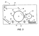
- FIG. 3 shows the basic elements of a typical electrophotographic printer 100.
- a document to be reproduced is placed on a platen 102 where it is illuminated by light source 104.
- the exposed document is imaged onto the photoreceptor 106 by a system of mirrors as shown.
- the optical image selectively discharges the surface of photoreceptor 106 in an image configuration, resulting in an electrostatic latent image of the original document recorded on the drum 106 at imaging station 108.
- the photoreceptor drum 106 rotates so that the latent image is moved towards development unit 110, where the electrostatic latent image is developed, by the application of toner particles.
- the main body of development unit 110 is encased in a developer housing 150, which accommodates a cylindrical toner cartridge 152.
- Toner cartridge 152 typically includes a rotatable agitator 154, which engages a rotating driver to keep the toner well-mixed and aerated so that toner 156 will flow easily and not coagulate. Opening 158 allows for removal of toner.
- Developer roll 160 comprises a stationary magnet assembly 162 enclosed within a rotating cylindrical sleeve 164.
- Stationary magnet assembly 162 includes a plurality of permanent magnets, with each magnet extending substantially the length of the developer roll 160, and arranged as known in the art such that the toner particles adhere to the surface of outer sleeve 164.
- the rotation of outer sleeve 164 causes the toner particles to move around the developer roll 160 to a development zone adjacent the surface of the photoreceptor 106.
- developer roll 160 is shown as having a rigid sleeve 164
- the "donor member” can be any member for conveying the toner particles to the development zone, such as a flexible belt.
- the ends of the developer roll 160 are intended to be ends of the cylinder formed by a rigid developer roll 160; if the donor member is in the form of a flexible belt, the ends are intended to be the lateral edges of the belt.
- Metering blade 168 smooths out the layer of toner particles on sleeve 164 so that the layer will be uniform when it is brought into contact with photoreceptor 106, and also to charge the toner.
- Metering blade 168 features a compressible pad 170 is anchored in position by a blade holder 172.
- the developed image is transferred at the transfer station 114 from photoreceptor 106 to a sheet of paper delivered from a paper supply system into contact with the drum 106 in synchronous relation to the image thereon.
- a transfer corotron 118 provides an electric field to assist in the transfer of the toner particles to the copy sheet.
- Individual sheets are introduced into the system from a stack of supply paper 126 by a friction feeder 128.
- a separated sheet is fed, in the embodiment shown, by further sets of nip roll pairs through a path indicated by the broken line.
- the image is subsequently fused onto the paper at fusing station 120 and the finished copy is deposited in hopper 122. Residual toner is removed from the photoreceptor drum 106 by cleaning blade 130, and then the surface is recharged by charging corotron 132, for imagewise discharging of the photoreceptor in a subsequent cycle.
- the developer roll advances the toner particles to a development zone adjacent the surface of the photoreceptor.
- the toner particles adhering magnetically to the developer roll are attracted electrostatically to the latent image recorded on the photoreceptor.
- AC and DC biases may be applied to the donor roll to enhance and control this process.
- Example 1 The mixture of Example 1 was passed through a single stage piston homogenizer (Niro Soavi Panda) at a pressure of greater than 800 bar. The coating mixture was then placed in a Tsukiagi cup coater and coated onto an 18mm diameter aluminum sleeve at a withdrawal rate of about 380 mm/min. The coated rod was allowed to air dry for about 40 minutes and then placed in an oven at 80°C for 30 min. to speed the removal of the water. The temperature was then slowly raised to about 140°C for 40 minutes and then raised to 150°C for another 30 minutes to cure the resin. The coating of the sleeve was complete and fairly uniform with some number of surface defects such as pinholes.
- Pinholes arise from some air entrainment in the coating dispersion and they will cause print defects; however these can be eliminated by one or a combination of two approaches: use of a recirculating reservoir for the diptank (rather than the static cup coating technique), or the optimization of the resin, e.g., substitution with other resins which are less prone to producing this type of defect, e.g., Neste BB317 resin.
- Example 1 16g of the mixture of Example 1 was combined with 140g of 0.125" diameter steel shot in a 120ml glass bottle. The bottle was tightly sealed and then milled for 18h at 300rpm. The thick meringue-like product was removed from the milling vessel and placed in the Tsukiage cup coater. An attempt to coat the 31cm long aluminum sleeve at 380 mm/min resulted in a very poor streaky coating on the first 3-4cm no deposition of material at all on the remaining length of the sleeve.
Landscapes
- Physics & Mathematics (AREA)
- General Physics & Mathematics (AREA)
- Dry Development In Electrophotography (AREA)
Abstract
The present invention relates to improved methods of
coating donor members with waterborne coatings, wherein a
resin, a pigment, and water are combined in proportions
effective to provide a donor member precursor composition;
the donor member precursor composition is subjected to high
pressure communition to provide a donor member conductive
coating composition; and the donor member coating
composition is coated onto a substrate. The present method
advantageously provides a donor member coating which is
substantially free of air pockets or defects. In preferred
embodiments the resin is a phenolic resin, preferably a
waterborne phenolic resin, such as a phenol-formaldehyde
resin, and in other preferred embodiments the pigment is
selected from the group consisting of carbon black,
graphite, magnetite, nigrosine, and combinations thereof.
Description
- The present invention relates to polymeric coatings for developer, or "donor" members used in electrophotographic image development systems. In xerography, or electrophotographic printing, a charge retentive surface called a photoreceptor is electrostatically charged, then exposed to a light pattern of an original image to selectively discharge the surface in accordance with the image, i.e., "imagewise". The resulting pattern of charged and discharged areas on the photoreceptor form an electrostatic charge pattern ("latent image") conforming to the original. The latent image is developed by contacting it with a finely divided electrostatically attractable powder called "toner." Toner is held on the image areas by the electrostatic charge on the photoreceptor surface. Thus, a toner image is produced in conformity with a light image of the original being reproduced. The toner image may then be transferred to a substrate or support member such as paper, and the image is affixed to the paper to form a the desired permanent image on the substrate. After development, excess toner left on the charge retentive surface is cleaned from the surface. The step of conveying toner to the latent image on the photoreceptor is known as "development". The object of effective development of a latent image on the photoreceptor is to convey toner particles to the latent image at a controlled rate so that the toner particles effectively adhere electrostatically to the appropriately-charged areas on the latent image.
- A commonly used development technique involves a single-component developer material. In a typical single-component development system, each toner particle has both magnetic properties, to allow the particles to be magnetically conveyed to the photoreceptor, and an electrostatic charge, to enable the particles to adhere to the photoreceptor. In such a system, the developer, or "donor" member is a cylindrical sleeve ("donor roll") which rotates about a stationary magnet assembly. The magnetized toner particles adhere to the rotating sleeve by the force of the stationary magnets within the sleeve. As the sleeve rotates around the magnets, particles adhering to the sleeve are exposed to an alternating series of magnetic polarities. The developer roll has a conductive coating which facilitates the adherence of toner to its surface. The coating typically includes a conductive pigment and a binder composition.
- The option of eliminating organic solvents from coating procedures has many benefits. It eliminates the need to build a coating plant to the stringent and costly Class I Division I or II ("explosion proof") specification for the use of flammable liquids. Since engineering controls, such as classified rooms and fume hoods, can only reduce the risk, there is a health and safety benefit to the plant operators in replacing organic solvents with water. The need to reclaim, destroy or account for the volatile organic compound (VOC) emissions is removed, which also provides cost savings. Also, by reducing or even eliminating VOC emissions, the plant design can be consistent in many locations, despite any variations in local regulations.
- The present invention relates to improved donor members having coatings thereupon which are made via an environmentally friendly process and without the drawbacks of prior attempts at water-based donor member coatings. Before the present invention, grinding of pigment into water-based phenolic resins, unlike organic-based coatings, was very likely to result in dispersion thickening and foaming. In extreme cases this foam is very stiff (meringue-like) and unsuitable for coating. Even small amounts of air entrainment can result in coating defects.
- The present invention relates to improved methods of coating donor members with waterborne coatings, wherein a resin, a pigment, and water are combined in proportions effective to provide a donor member precursor composition; the donor member precursor composition is subjected to high pressure communition to provide a donor member conductive coating composition; and the donor member coating composition is coated onto a substrate. The present method advantageously provides a donor member coating which is substantially free of air pockets or other defects. The resin may be a phenolic resin, preferably a waterborne phenolic resin, such as Durez 33304 (Oxychem Chemical Corporation) or BB 317 (Neste Chemical), and in other preferred embodiments the pigment may be, e.g., carbon black, graphite, magnetite, nigrosine, or a combination of these pigments.
- The high pressure communition step may be carried out using a high pressure communition device such as a piston homogenizer. One or two stage homogenizers may be used. In another embodiment, the invention defines an image forming apparatus which has a charge-retentive surface to receive an electrostatic latent image, and a donor member for applying a developer material to develop the electrostatic latent image to form a developed image. The donor member is coated with a waterborne donor member coating composition prepared as described herein.
- In yet another embodiment, the invention relates to coated donor rolls having a core with a coating composition thereupon, the donor member coating composition prepared by combining a resin, a pigment, and water in proportions effective to provide a donor member coating precursor composition; and subjecting the donor member coating precursor composition to high pressure communition.
- Also included in this invention is an image forming apparatus including a charge-retentive surface for receiving an electrostatic latent image, and a donor roll having a core and a donor member coating prepared by a combining a resin, a conductive pigment, and water in proportions effective to provide a donor member conductive coating precursor composition, and subjecting the donor member conductive coating precursor composition to high pressure communition; and a transfuse component for transferring and fusing the developed image from the charge retentive surface to a copy substrate.
- In another embodiment the invention encompasses an image forming apparatus having a charge-retentive surface for receiving an electrostatic latent image; and a donor roll to apply a developer material to the charge-retentive surface to develop the electrostatic latent image and form a developed image on the charge retentive surface. The donor roll is coated with a waterborne donor member coating composition of the invention. The image forming apparatus further includes a transfer component to transfer the developed image from the charge retentive surface to a copy substrate; and a fixing component to fuse the transferred developed image to the copy substrate.
- In an even further embodiment, the invention includes an image forming apparatus for forming images on a recording medium, which has a charge-retentive surface for receiving an electrostatic latent image; and a donor roll with a core and a coating of the present invention for applying a developer material to the charge-retentive surface to develop the electrostatic latent image to form a developed image on the charge retentive surface. The apparatus also includes a transfuse component for transferring the developed image from the charge retentive surface to a copy substrate, and for fusing the developed image to the copy substrate.
- A particular embodiment and examples will now be described with reference to the accompanying drawings; in which:-
- FIG. 1 is a sectional, elevational view showing a detail of the development apparatus of an electrophotographic printer;
- FIG. 2 is a sectional view through line 2--2 in FIG. 1, showing the configuration of a metering blade relative to a donor roll when the metering blade is separated from the donor roll and there is no toner in the system; and
- FIG. 3 is an elevational view showing the basic elements of a typical electrophotographic printer.
-
- The present invention provides for water-based coating materials which allow for preparing donor members, advantageously avoiding thickening and foaming, i.e., undesirable air entrainment, which almost inevitably results in coating defects, the coatings obtained are suitable for high quality images with solid area development greater than 1.3 and the absence of ghosting.
- The present invention encompasses improved methods of coating donor members with waterborne coatings. A resin, a pigment, and water are combined in proportions effective to provide a donor member coating precursor composition, and the donor member coating precursor composition is subjected to high pressure communition to thoroughly disperse the ingredients. A conductive donor member coating results which can then be coated onto a substrate, i.e., a donor roll core. The present method advantageously provides a donor member coating which is substantially free of air pockets or other defects.
- "Waterborne coatings" in accordance with the present invention have water as a substantial part of the carrier portion of the coating composition, e.g., greater than 75%, 80%, 85%, 90%, or 95% of the carrier. While other solvents may be included it is more desirable that the composition be mostly water to preserve the benefits of little or no VOC emission.
- "Donor member coating precursor composition" includes compositions of the invention which are prepared prior to high pressure communition, i.e., compositions including resin, a conductive pigment, and water in effective proportions for donor members. The precursor composition ingredients may be mixed together, or, more desirably, simple homogenization, e.g., with a rotor stator mixer.
- In preferred embodiments the resin is a phenolic resin, preferably a waterborne phenolic resin, such as Durez 33304 (Oxychem Chemical Corporation) or BB 317 (Neste Chemical). "Phenolic resin" includes art-recognized compositions falling under this classification, e.g., phenol-formaldehyde resoles. Resoles are phenolic resins made by combining an excess of formaldehyde with phenolic compounds and are typically alkaline, imparting the potential for such resins to be waterborne. Typical novolac resins, by contrast, does not have an excess of formaldehyde and is acidic, making it difficult to be carried in a water based vehicle. The solids loading of the present coating dispersion is from about 25% to 30% (% by weight) in water. The solids component preferably contains about 50% to 75% waterborne phenolic resin, preferably about 55%-65%; about 20% to 40% graphite particles, preferably about 26%-30%; and about 5% to 20% of conductive carbon black, preferably about 9%-13%.
- The pigment may be, e.g., carbon black, graphite, magnetite, nigrosine, or combinations of pigments. Preferably both carbon black and graphite are used. The solids loading of the coating dispersion is from about 25% to 30% in water, with the solids component containing about 20% to 40 % of graphite particles, preferably 26-30 wt%; and about 5% to 20% conductive carbon black such as Conductex 975 (Columbia Chemical Corp.), preferably 9%-13%. Exemplary graphite particles include Rollit DS-1010 (Timcal), CSPE (Nippon Graphite), and M890 (Asbury Graphite)
- The high pressure communition may be carried out using a device such as a piston homogenizer, e.g., one or two stage homogenizers. High pressure communition devices such as piston homogenizers or a Microfluidizer® share a similar mechanism of particle breakdown. Both drive a fluid at high pressure through a small orifice, the homogenizer valve in the former, and the interaction chamber in the latter. The resulting shear and cavitation breaks down agglomerates and disperses particles in the fluid. With a piston homogenizer, a second stage valve can also be employed to reduce the fluid viscosity that often increases after the first stage disperses the colloidal pigments. While both types of devices are applicable, a piston homogenizer is more readily operated and serviced. These devices also offer much faster throughput than media mills.
- Various process options are available with a piston homogenizer; the principle parameters are pressure, number of passes through the homogenizer valve, and the valve configuration itself. The most important variable is pressure, good results may be obtained with a pressure of about 1000 to 1500 bar, preferably 1100 to 1200 bar. Near equivalent results may be achieved by two passes through the homogenizer at 800 bar, but this appears to be less efficient.
- The coating compositions of the invention may be used to provide improved toner donor member coatings as well as overcoatings for electrophotographic development sub-system donor members, and may also be used to protect electrodes on a donor member from wear, and/or to prevent electrical shorting with a developer material's conductive carrier beads. Specific examples of coatings of the invention, and their application to developer members, are detailed below in the Examples.
- One aspect of the present invention includes apparatus for applying toner particles on a charge-retentive surface to develop an electrostatic latent image on the charge-retentive surface. A donor member such as a roll and rotatable in a process direction, conveys toner particles on a surface thereof from a supply of toner particles to a development zone close to the charge-retentive surface.
- Another embodiment of the present invention includes an electrostatographic printing apparatus featuring a charge-retentive surface which is adapted to retain an electrostatic latent image, and a supply of toner particles. A donor member such as a roll rotates and conveys toner particles on its surface from the toner supply to a development zone close to the charge-retentive surface.
- Since the art of electrophotographic printing is well known, the various processing stations employed in a printing machine will be shown schematically and their operation described briefly.
- FIG. 3 shows the basic elements of a typical
electrophotographic printer 100. A document to be reproduced is placed on aplaten 102 where it is illuminated bylight source 104. The exposed document is imaged onto thephotoreceptor 106 by a system of mirrors as shown. The optical image selectively discharges the surface ofphotoreceptor 106 in an image configuration, resulting in an electrostatic latent image of the original document recorded on thedrum 106 atimaging station 108. Thephotoreceptor drum 106 rotates so that the latent image is moved towardsdevelopment unit 110, where the electrostatic latent image is developed, by the application of toner particles. - The main body of
development unit 110 is encased in adeveloper housing 150, which accommodates acylindrical toner cartridge 152.Toner cartridge 152 typically includes arotatable agitator 154, which engages a rotating driver to keep the toner well-mixed and aerated so thattoner 156 will flow easily and not coagulate.Opening 158 allows for removal of toner.Developer roll 160 comprises astationary magnet assembly 162 enclosed within a rotatingcylindrical sleeve 164.Stationary magnet assembly 162 includes a plurality of permanent magnets, with each magnet extending substantially the length of thedeveloper roll 160, and arranged as known in the art such that the toner particles adhere to the surface ofouter sleeve 164. The rotation ofouter sleeve 164 causes the toner particles to move around thedeveloper roll 160 to a development zone adjacent the surface of thephotoreceptor 106. - Although
developer roll 160 is shown as having arigid sleeve 164, the "donor member" can be any member for conveying the toner particles to the development zone, such as a flexible belt. The ends of thedeveloper roll 160 are intended to be ends of the cylinder formed by arigid developer roll 160; if the donor member is in the form of a flexible belt, the ends are intended to be the lateral edges of the belt.Metering blade 168 smooths out the layer of toner particles onsleeve 164 so that the layer will be uniform when it is brought into contact withphotoreceptor 106, and also to charge the toner.Metering blade 168 features acompressible pad 170 is anchored in position by ablade holder 172. - The developed image is transferred at the
transfer station 114 fromphotoreceptor 106 to a sheet of paper delivered from a paper supply system into contact with thedrum 106 in synchronous relation to the image thereon. Atransfer corotron 118 provides an electric field to assist in the transfer of the toner particles to the copy sheet. Individual sheets are introduced into the system from a stack ofsupply paper 126 by afriction feeder 128. A separated sheet is fed, in the embodiment shown, by further sets of nip roll pairs through a path indicated by the broken line. The image is subsequently fused onto the paper at fusingstation 120 and the finished copy is deposited inhopper 122. Residual toner is removed from thephotoreceptor drum 106 by cleaningblade 130, and then the surface is recharged by chargingcorotron 132, for imagewise discharging of the photoreceptor in a subsequent cycle. - When a thin layer of uniformly-charged particles is obtained, the developer roll advances the toner particles to a development zone adjacent the surface of the photoreceptor. In the development zone, the toner particles adhering magnetically to the developer roll are attracted electrostatically to the latent image recorded on the photoreceptor. AC and DC biases may be applied to the donor roll to enhance and control this process.
- The invention is further illustrated by the following examples, which should not be construed as further limiting the subject invention.
- In a 1L polyethylene container 27.9g of graphite (Nippon graphite CSPE), 14.2g carbon black (Columbia, Conductex 975), 106g Durez 33304 phenolic resin (Occidental Chemical Corp.) and 140ml DI water were combined to make a donor member precursor composition. The precursor composition was homogenized with a 2" rotor stator mixer at about 12000 rpm for one minute, stopped for five minutes, processed for two minutes, stopped for five, and then processed for another two minutes, while maintaining the vessel in an ice bath.
- The mixture of Example 1 was passed through a single stage piston homogenizer (Niro Soavi Panda) at a pressure of greater than 800 bar. The coating mixture was then placed in a Tsukiagi cup coater and coated onto an 18mm diameter aluminum sleeve at a withdrawal rate of about 380 mm/min. The coated rod was allowed to air dry for about 40 minutes and then placed in an oven at 80°C for 30 min. to speed the removal of the water. The temperature was then slowly raised to about 140°C for 40 minutes and then raised to 150°C for another 30 minutes to cure the resin. The coating of the sleeve was complete and fairly uniform with some number of surface defects such as pinholes. Pinholes arise from some air entrainment in the coating dispersion and they will cause print defects; however these can be eliminated by one or a combination of two approaches: use of a recirculating reservoir for the diptank (rather than the static cup coating technique), or the optimization of the resin, e.g., substitution with other resins which are less prone to producing this type of defect, e.g., Neste BB317 resin.
- To illustrate the differences in the coating compositions of the present invention in light of prior art methods, e.g., to illustrate that media mills entrain too much air in these formulations to provide a useful coating dispersion, 16g of the mixture of Example 1 was combined with 140g of 0.125" diameter steel shot in a 120ml glass bottle. The bottle was tightly sealed and then milled for 18h at 300rpm. The thick meringue-like product was removed from the milling vessel and placed in the Tsukiage cup coater. An attempt to coat the 31cm long aluminum sleeve at 380 mm/min resulted in a very poor streaky coating on the first 3-4cm no deposition of material at all on the remaining length of the sleeve.
Claims (8)
- A method of coating a donor member with a waterborne coating, comprising(a) combining a resin, a pigment, and water in proportions effective to provide a donor member coating precursor composition;(b) subjecting said donor member coating precursor composition to high pressure communition to provide a donor member conductive coating composition; and(c) coating said donor member coating composition onto a substrate.
- A method according to claim 1, wherein said coating step comprises coating said donor member conductive coating composition onto said substrate to a thickness of from about 3 to about 50µ.
- A method of preparing a donor member coating, comprising:(a) combining a resin, a pigment, and water in proportions effective to provide a donor member precursor composition; and(b) subjecting said donor member coating precursor composition to high pressure communition to provide a donor member conductive coating composition.
- A method according to claim 1, 2 or 3, wherein said combining step comprises dispersing said pigment into said donor member coating composition without resulting in substantial foaming or air entrainment.
- A method according to any one of the preceding claims, wherein said resin is a phenolic resin.
- A method according to claim 4, wherein said phenolic resin is a waterborne phenolic resin.
- A method according to any one of the preceding claims, wherein said pigment is a conductive pigment.
- A method according to any one of the preceding claims, wherein said pigment is carbon black or graphite or magnetite or nigrosine or combinations thereof.
Priority Applications (1)
| Application Number | Priority Date | Filing Date | Title |
|---|---|---|---|
| EP02253713A EP1367457A1 (en) | 2002-05-27 | 2002-05-27 | Method of coating a donor member |
Applications Claiming Priority (1)
| Application Number | Priority Date | Filing Date | Title |
|---|---|---|---|
| EP02253713A EP1367457A1 (en) | 2002-05-27 | 2002-05-27 | Method of coating a donor member |
Publications (1)
| Publication Number | Publication Date |
|---|---|
| EP1367457A1 true EP1367457A1 (en) | 2003-12-03 |
Family
ID=29414809
Family Applications (1)
| Application Number | Title | Priority Date | Filing Date |
|---|---|---|---|
| EP02253713A Withdrawn EP1367457A1 (en) | 2002-05-27 | 2002-05-27 | Method of coating a donor member |
Country Status (1)
| Country | Link |
|---|---|
| EP (1) | EP1367457A1 (en) |
Citations (4)
| Publication number | Priority date | Publication date | Assignee | Title |
|---|---|---|---|---|
| GB385344A (en) * | 1930-08-06 | 1932-12-29 | Chemische Und Seifenfabrik R B | A process of producing resin emulsions |
| US5071904A (en) * | 1989-05-30 | 1991-12-10 | Ppg Industries, Inc. | Waterborne coating compositions for automotive applications |
| EP0933384A1 (en) * | 1998-01-28 | 1999-08-04 | National Starch and Chemical Investment Holding Corporation | Process for preparing epoxy-acrylic hybrid emulsions |
| JP2001201934A (en) * | 2000-01-19 | 2001-07-27 | Fuji Xerox Co Ltd | Developer carrier and its manufacturing method |
-
2002
- 2002-05-27 EP EP02253713A patent/EP1367457A1/en not_active Withdrawn
Patent Citations (4)
| Publication number | Priority date | Publication date | Assignee | Title |
|---|---|---|---|---|
| GB385344A (en) * | 1930-08-06 | 1932-12-29 | Chemische Und Seifenfabrik R B | A process of producing resin emulsions |
| US5071904A (en) * | 1989-05-30 | 1991-12-10 | Ppg Industries, Inc. | Waterborne coating compositions for automotive applications |
| EP0933384A1 (en) * | 1998-01-28 | 1999-08-04 | National Starch and Chemical Investment Holding Corporation | Process for preparing epoxy-acrylic hybrid emulsions |
| JP2001201934A (en) * | 2000-01-19 | 2001-07-27 | Fuji Xerox Co Ltd | Developer carrier and its manufacturing method |
Non-Patent Citations (1)
| Title |
|---|
| PATENT ABSTRACTS OF JAPAN vol. 2000, no. 24 11 May 2001 (2001-05-11) * |
Similar Documents
| Publication | Publication Date | Title |
|---|---|---|
| US7024141B2 (en) | Developing device and process cartridge for an image forming apparatus | |
| EP0478317B1 (en) | Apparatus for developing electrostatic latent image and developing roller therefor | |
| US5155532A (en) | Method for developing an electrostatic latent image | |
| US6701114B2 (en) | Image forming apparatus and image forming process unit with developer carried on a developer carrier | |
| US7103305B2 (en) | Developing apparatus for image forming apparatus | |
| JPH06348101A (en) | Toning and fixing method by mixing primary color toners | |
| JPH05210299A (en) | Electrophotographic printing machine | |
| US6456815B1 (en) | Developer apparatus including a coated developer roller | |
| US4579082A (en) | Developing apparatus | |
| JP2003280284A (en) | Developer carrier, developer and image forming method | |
| JP3978824B2 (en) | Two-component developer and electrophotographic method | |
| JP2003345095A (en) | Method for producing electrophotographic member and member for electrophotography produced by the method | |
| US6410637B1 (en) | Water-based composition for coating a donor member | |
| EP1367095B1 (en) | Water-based composition for coating a donor member | |
| US4849317A (en) | Magnetic brush developer for electrophotography | |
| US6965746B2 (en) | Hybrid electrophotographic development with toner induction charged via AC induced conductivity | |
| US9026013B2 (en) | System and apparatus for toner charging using charge/metering blade having an adjustable nip | |
| JP2004012727A (en) | Developing device possessing coated developing roller | |
| JP6170874B2 (en) | Developing device, developing method, and image forming apparatus | |
| JP2004010705A (en) | Aqueous composition for coating donor member | |
| JP4579779B2 (en) | Image forming method | |
| JPH07209910A (en) | Toner and electrophotographic device | |
| JP2004198833A (en) | Toner manufacturing method, developing device, process cartridge, and image forming apparatus | |
| JP3690051B2 (en) | Electrophotographic developer carrier, electrophotographic developer, and image forming apparatus | |
| JP4250213B2 (en) | Image forming apparatus |
Legal Events
| Date | Code | Title | Description |
|---|---|---|---|
| PUAI | Public reference made under article 153(3) epc to a published international application that has entered the european phase |
Free format text: ORIGINAL CODE: 0009012 |
|
| AK | Designated contracting states |
Kind code of ref document: A1 Designated state(s): AT BE CH CY DE DK ES FI FR GB GR IE IT LI LU MC NL PT SE TR |
|
| AX | Request for extension of the european patent |
Extension state: AL LT LV MK RO SI |
|
| 17P | Request for examination filed |
Effective date: 20040603 |
|
| AKX | Designation fees paid |
Designated state(s): DE FR GB NL |
|
| 17Q | First examination report despatched |
Effective date: 20061011 |
|
| STAA | Information on the status of an ep patent application or granted ep patent |
Free format text: STATUS: THE APPLICATION IS DEEMED TO BE WITHDRAWN |
|
| 18D | Application deemed to be withdrawn |
Effective date: 20141202 |