EP1367409A2 - System and method for focusing SAR images - Google Patents
System and method for focusing SAR images Download PDFInfo
- Publication number
- EP1367409A2 EP1367409A2 EP03012412A EP03012412A EP1367409A2 EP 1367409 A2 EP1367409 A2 EP 1367409A2 EP 03012412 A EP03012412 A EP 03012412A EP 03012412 A EP03012412 A EP 03012412A EP 1367409 A2 EP1367409 A2 EP 1367409A2
- Authority
- EP
- European Patent Office
- Prior art keywords
- image
- data
- phase
- signal support
- support areas
- Prior art date
- Legal status (The legal status is an assumption and is not a legal conclusion. Google has not performed a legal analysis and makes no representation as to the accuracy of the status listed.)
- Granted
Links
Images




Classifications
-
- G—PHYSICS
- G01—MEASURING; TESTING
- G01S—RADIO DIRECTION-FINDING; RADIO NAVIGATION; DETERMINING DISTANCE OR VELOCITY BY USE OF RADIO WAVES; LOCATING OR PRESENCE-DETECTING BY USE OF THE REFLECTION OR RERADIATION OF RADIO WAVES; ANALOGOUS ARRANGEMENTS USING OTHER WAVES
- G01S13/00—Systems using the reflection or reradiation of radio waves, e.g. radar systems; Analogous systems using reflection or reradiation of waves whose nature or wavelength is irrelevant or unspecified
- G01S13/88—Radar or analogous systems specially adapted for specific applications
- G01S13/89—Radar or analogous systems specially adapted for specific applications for mapping or imaging
- G01S13/90—Radar or analogous systems specially adapted for specific applications for mapping or imaging using synthetic aperture techniques, e.g. synthetic aperture radar [SAR] techniques
- G01S13/9004—SAR image acquisition techniques
- G01S13/9011—SAR image acquisition techniques with frequency domain processing of the SAR signals in azimuth
-
- G—PHYSICS
- G01—MEASURING; TESTING
- G01S—RADIO DIRECTION-FINDING; RADIO NAVIGATION; DETERMINING DISTANCE OR VELOCITY BY USE OF RADIO WAVES; LOCATING OR PRESENCE-DETECTING BY USE OF THE REFLECTION OR RERADIATION OF RADIO WAVES; ANALOGOUS ARRANGEMENTS USING OTHER WAVES
- G01S13/00—Systems using the reflection or reradiation of radio waves, e.g. radar systems; Analogous systems using reflection or reradiation of waves whose nature or wavelength is irrelevant or unspecified
- G01S13/88—Radar or analogous systems specially adapted for specific applications
- G01S13/89—Radar or analogous systems specially adapted for specific applications for mapping or imaging
- G01S13/90—Radar or analogous systems specially adapted for specific applications for mapping or imaging using synthetic aperture techniques, e.g. synthetic aperture radar [SAR] techniques
- G01S13/9004—SAR image acquisition techniques
- G01S13/9019—Auto-focussing of the SAR signals
-
- G—PHYSICS
- G01—MEASURING; TESTING
- G01S—RADIO DIRECTION-FINDING; RADIO NAVIGATION; DETERMINING DISTANCE OR VELOCITY BY USE OF RADIO WAVES; LOCATING OR PRESENCE-DETECTING BY USE OF THE REFLECTION OR RERADIATION OF RADIO WAVES; ANALOGOUS ARRANGEMENTS USING OTHER WAVES
- G01S13/00—Systems using the reflection or reradiation of radio waves, e.g. radar systems; Analogous systems using reflection or reradiation of waves whose nature or wavelength is irrelevant or unspecified
- G01S13/88—Radar or analogous systems specially adapted for specific applications
- G01S13/89—Radar or analogous systems specially adapted for specific applications for mapping or imaging
- G01S13/90—Radar or analogous systems specially adapted for specific applications for mapping or imaging using synthetic aperture techniques, e.g. synthetic aperture radar [SAR] techniques
- G01S13/904—SAR modes
-
- G—PHYSICS
- G01—MEASURING; TESTING
- G01S—RADIO DIRECTION-FINDING; RADIO NAVIGATION; DETERMINING DISTANCE OR VELOCITY BY USE OF RADIO WAVES; LOCATING OR PRESENCE-DETECTING BY USE OF THE REFLECTION OR RERADIATION OF RADIO WAVES; ANALOGOUS ARRANGEMENTS USING OTHER WAVES
- G01S13/00—Systems using the reflection or reradiation of radio waves, e.g. radar systems; Analogous systems using reflection or reradiation of waves whose nature or wavelength is irrelevant or unspecified
- G01S13/88—Radar or analogous systems specially adapted for specific applications
- G01S13/89—Radar or analogous systems specially adapted for specific applications for mapping or imaging
- G01S13/90—Radar or analogous systems specially adapted for specific applications for mapping or imaging using synthetic aperture techniques, e.g. synthetic aperture radar [SAR] techniques
- G01S13/904—SAR modes
- G01S13/9041—Squint mode
Definitions
- the present invention relates to radar signal processing systems. More specifically, the present invention relates to phase error correction in a range migration algorithm (RMA) for synthetic aperture radar (SAR) systems.
- RMA range migration algorithm
- SAR synthetic aperture radar
- a radar system In imaging applications such as ground mapping, a radar system is used to generate a two-dimensional image of a portion of a ground surface in the range and azimuth (cross-range) directions.
- a large antenna aperture is required in conventional imaging radar systems in order to achieve a narrow beamwidth and, consequently, fine azimuth resolution.
- Synthetic aperture radar (SAR) systems have been developed as an alternative means for improving azimuth resolution by synthesizing pulse-to-pulse return signals collected by a moving platform with a small antenna. Signal synthesis :from many successive locations of the moving platform accomplishes what would otherwise require a larger antenna aperture.
- a polar format algorithm has been widely used for high-resolution SAR systems.
- the PFA has the shortcomings of limited depth of focus and geometric distortion that increases with the map size.
- Range migration algorithm is one of the most attractive and advanced SAR processing techniques to avoid the problems with the PFA.
- a difficulty with the RMA is performing efficient phase correction.
- phase correction is more complicated and requires additional processing.
- a currently used method performs phase correction through separate processing in the pulse-to-pulse phase using PFA.
- the need in the art is addressed by the present invention, a system and method for focusing an image oriented in an arbitrary direction when the collected synthetic aperture radar (SAR) data is processed using range migration algorithm (RMA).
- RMA range migration algorithm
- first the data is skewed so that the direction of smearing in the image is aligned with one of the spatial frequency axes of the image.
- the smearing is aligned in the vertical direction. This is done through a phase adjustment that was derived from the requirements for proper shift in the spatial frequency domain.
- the signal support areas from all targets are aligned by proper phase adjustment in the spatial (or image) domain.
- the common phase error is then estimated and corrected using autofocus algorithms.
- the remaining steps include reverse shifting and deskew processing for the reversal of the processing performed earlier for the alignment of common phase error.
- Uncompensated phase error in collected data for synthetic aperture radar (SAR) systems causes image smearing in the azimuth (cross-range) direction. This is due mainly to uncompensated slow motion error that occurs as the Doppler cone angle changes during the time of data collection.
- SAR images are formed in the range and azimuth direction, image smearing that occurs in the azimuth direction (usually the vertical axis in the SAR display) can readily be corrected by compensating estimated phase error in the azimuth direction only using various autofocus techniques.
- Figs. 1a and 1b are illustrations showing the direction of smearing in an image I oriented in range-azimuth with a Doppler cone angle ⁇ measured from the along track direction V .
- the direction of smearing is in the azimuth direction, which is along the vertical axis of the image as shown in Fig. 1b.
- Figs. 1c and 1d are illustrations showing the direction of smearing in an image I' oriented in along track-cross track (AT-CT) with a Doppler cone angle ⁇ measured from the along track direction V .
- the direction of smearing is still in the azimuth direction.
- the direction of smearing is not along the vertical axis of the image as shown in Fig. 1d.
- the proposed method performs a data skew by applying proper phase adjustments so that the direction of smearing is converted to the desirable vertical direction before applying autofocus algorithms. Inverse processing needs to be performed after phase correction using autofocus algorithms.
- RMA range migration algorithm
- Shifting of the signal support for the RMA processing includes basic shifting of signal support and secondary shifting due to the conversion of the smearing direction as mentioned.
- Fig. 2 is an illustration showing a general case that has a Doppler cone angle ⁇ and an image orientation angle ⁇ 1 from the along-track direction V.
- the Y axis of the image is at an angle ⁇ 1 from the along-track direction V
- the X axis of the image is at an angle ⁇ 1 - ⁇ from the azimuth direction. Since the spectrum corresponding to the processed image in the spatial frequency domain before the last two-dimensional inverse FFT in the image formation processing chain has the same orientation with the image orientation, pulse-to-pulse phase error occurs at an angle ⁇ 1 - ⁇ from the vertical axis ( K X ) as indicated in Fig. 3.
- Fig. 3 is an illustration showing the direction of pulse-to-pulse phase variation in the spatial frequency domain.
- the pulse-to-pulse phase variation occurs in a direction that couples two axes, the image cannot be focused by one-dimensional phase correction. Therefore, to use one-dimensional phase correction algorithms, it is required to convert the data such that the direction of phase variation can be changed to either the vertical or horizontal direction.
- Fig. 4 illustrates the data conversion from (K X , K Y ) to (K and X , K and Y ) to align the phase error variation to the vertical direction.
- K X K X - tan( ⁇ 1 - ⁇ ) ⁇ K Y
- Fig. 5 shows the geometry for an image with arbitrary orientation with targets a and b at the map center (0,0) and at coordinates ( X,Y ), respectively.
- Target a is located at an angle ⁇ from the along-track direction V, at a distance R from the radar.
- Target b is located at an angle ⁇ t from the along-track direction V.
- the mapping geometry in Fig. 5 will be used to derive the required shift correction based on the calculated target angle off line-of-sight (LOS).
- LOS line-of-sight
- Fig. 6 is an illustration showing the signal support areas A and B corresponding to targets a and b, respectively.
- the signal support areas A and B are shifted by an angle ⁇ - ⁇ 1 .
- the shifting of the signal support is determined by the azimuth location of the targets.
- phase error was changed to align to the vertical (K x ) direction as discussed above, shifting of the signal support can be done in the vertical direction.
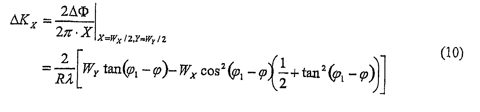
- phase adjustment required in the spatial domain to compensate for a shift in K X is given by:
- ⁇ K X 1 / 2 ⁇ ⁇ 1 / ⁇ X .
- ⁇ 1 has the expression:
- Fig. 7 is an illustration showing the shifting of the signal support in Kx only as a function of target location in cross range.
- the present invention provides a system and method for efficient phase error correction in RMA for images with arbitrary orientation.
- the proposed method performs data skew by applying the proper phase adjustment, as discussed above, so that the direction of smearing is converted to the desirable vertical direction.
- the signal support for each target is shifted so that the common phase error is aligned.
- the shifting of the signal support includes both basic shifting of signal support and secondary shifting due to the conversion of the smearing direction as discussed above.
- the common phase error can be corrected using known autofocus algorithms. Reverse processing of the previously performed phase adjustments needs to be performed after phase correction.
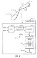
- Fig. 8 is a simplified block diagram of an airborne SAR system using RMA with the new phase correction scheme in accordance with the teachings of the present invention.
- a SAR system 16 mounted on an aircraft 10 generates an electromagnetic wave 12 which is reflected off a ground surface 14 and received by the SAR system 16.
- the SAR system 16 includes an antenna 20, a transmitter 22, and a receiver 24 for radiating and receiving the electromagnetic waves.
- the receiver 24 forms input video phase history (VPH) data 28 from the received data and sends it to an on-board signal processor 26.
- VPH video phase history
- Residing in the signal processor 26 is a range migration algorithm 30 with the new phase correction scheme of the present teachings, which outputs a focused image 50.
- Fig. 9 is a simplified block diagram showing the basic components of RMA and where the new phase correction scheme should be inserted in accordance with the teachings of the present invention.
- the basic components of RMA are well known in the art.
- the input VPH data 28 is successively passed through a Motion Compensation function 32, a Range Deskew function 34, an Along-Track FFT 26, a Matched Filter 38, and a Stolt Interpolation 40.
- the new phase correction scheme 44 is inserted after the Stolt Interpolation 40, generating a final focused image 50.
- Fig. 10 is a simplified block diagram showing the basic components of the new phase correction scheme 44 in accordance with the teachings of the present invention.
- Interpolated data 58 output from the Stolt Interpolation 40 is first passed through a Skew function 60, followed by a Phase Shift 62, and an Autofocus function 64. After Autofocus 64, a Reverse Shift 66 and Deskew 68 are applied. Finally, a 2D FFT 70 is applied to form a focused image 50.
- the proposed phase correction method needs to be implemented in the spatial frequency domain after the Stolt Interpolation 40. Proper zero padding is required to avoid the wrap-around effect in the process of performing FFT functions.
- the first case is when the interpolated data in the spatial frequency domain ( K X , K Y ) has the minimum size in K X that is required for the desired resolution. Since phase error is estimated using the shifted spectra of each target, the estimated phase error in this case may be less accurate around the azimuth edge in the spatial frequency domain.
- the second case is when the interpolated data in the spatial frequency domain has extra length in K X so that the overlapped area is big enough for phase correction of the desired length during and after forward and backward shifting.
- Figs. 11a-11c show the data length variation for the case with minimum spectral data size.
- Fig. 11a shows the interpolated data after the Stolt interpolation in the (K X , K Y ) domain.
- the data lengths in K X and K Y are DK Xmin and DK Y , respectively.
- Fig. 11b shows the data position after data skewing to change smearing to the vertical direction.
- the data length in K X becomes DK X min + DK Y tan( ⁇ 1 - ⁇ ).
- Fig. 11 c shows the data position after data shifting in K X .
- the data length in K X becomes DK Xmin + DK Y tan( ⁇ 1 - ⁇ ) + 2(2/ ⁇ ) ⁇ max .
- SVA spatially variant apodization
- Figs. 12a-12c show the data length variation for the case with extended spectral data size.
- Fig. 12a shows the interpolated data after the Stolt interpolation in the (K X , K Y ) domain.
- Fig. 12b shows the data position after data skewing to change smearing to the vertical direction.
- the data length in in K X becomes DK X + DK Y tan( ⁇ 1 - ⁇ ).
- Fig. 12c shows the data position after data shifting in K X .
- the data length in K X becomes DK X + DK Y tan( ⁇ 1 - ⁇ ) + 2(2 / ⁇ ) ⁇ max . Since phase information from every target in the mapping area is available after spectral shifting, phase correction performance should be better than the case with the minimum spectral size. There is still a small area that is not covered by the data collection as indicated in the first spectral rectangle in Fig. 12a. If desired, this can be avoided by taking extra samples in K Y as indicated by dotted lines.
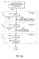
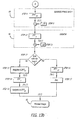
- Figs. 13a and 13b are flow diagrams of the new phase correction algorithm in accordance with the teachings of the present invention.
- the flow chart begins in Fig. 13a and is continued in Fig. 13b.
- an inverse Fast Fourier Transform (IFFT) function in K X is applied to the data to convert it to the spatial domain so that the phase adjustment ⁇ in Eqn. (3) can be applied in STEP 3 for shifting in K X as a function of K Y .
- the data is in the ( X, K Y ) domain.
- phase adjustment ⁇ in Eqn. (3) is applied.
- Application of this phase in the ( X, K Y ) domain is for skewing the data to make the angled smearing aligned to the vertical direction.
- an inverse Fast Fourier Transform (IFFT) in K Y is applied to convert the data to the image ( X, Y ) domain so that the phase adjustment in STEP 5 can be performed to align the shifted common phase error as a function of azimuth position.
- IFFT inverse Fast Fourier Transform
- phase adjustment function ⁇ expressed in Eqn. (9) is applied to align the shifted target spectra so that the common phase error can be properly estimated and corrected using an autofocus function in STEP 7.
- a forward FFT function in X is applied to convert the data in X to K X so that the common phase error can be estimated and corrected by the subsequent autofocus function (STEP 7). After this step, the data is in the (K X , Y ) domain.
- any parametric or non-parametric autofocus algorithm or combination of algorithms can be applied to estimate and correct the phase error common to all targets using the shift-corrected range compressed data in the K X domain.
- an inverse FFT in K X is applied to convert the phase corrected data to the image (spatial) domain so that a reverse phase shift (- ⁇ ) can be applied in STEP 9 to restore the shifted signal support.
- a forward FFT function in 7 is applied to convert data from Y to K Y so that the deskew function (- ⁇ ) in STEP 11 can be applied.
- the data is in the ( X , K Y ) domain.
- a deskew phase function (- ⁇ ) is applied to shift back the shifted image in Y for a given position in X , reversing the skew function applied in STEP 3.
- STEP 12 if SVA is used with the input spectrum of minimum length, go to STEP 16; otherwise, go to STEP 13.
- a forward FFT in X is applied to convert the data to K X so that data of the correct size is taken and a weighting function can be applied.
- weights and an inverse FFT in K X are applied to compress the data in X , forming a final focused image 50.
- an inverse FFT in K Y is applied to compress the data in Y without weighting so that SVA can be applied in STEP 17.
- the data is in the image domain ( X, Y ).
- STEP 17 a two dimensional SVA is applied to reduce the sidelobe level while maintaining the mainlobe width minimum.
- the SVA function outputs a final focused image 50.
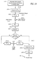
- Phase correction becomes much simpler when the processed image is oriented in the range-azimuth direction. This is because there is no need to include the phase adjustment by ⁇ to align the direction of smearing to the vertical. As a result, steps 3, 10, 11, 13, and 16 in Fig. 13 can be eliminated. Since ( ⁇ 1 - ⁇ ) is zero, ⁇ that is expressed in Eqn. (9) is not a function of the range variable Y any more. Simplified processing steps with these adjustments from Fig. 13 are illustrated in Fig. 14.
- Fig. 14 is a flow chart showing the simplified processing sequence for focusing RMA-based SAR images oriented in range-azimuth. The sequence is similar to that of Fig. 13 with STEPS 3, 10, 11, 13, and 16 eliminated. After autofocusing (STEP 7), if the input data was of extended length, then STEPS 8, 9 and 14 are performed. Otherwise, those steps are skipped. Then STEPS 15 and 17 are applied, generating the final focused image 50.
Landscapes
- Engineering & Computer Science (AREA)
- Remote Sensing (AREA)
- Radar, Positioning & Navigation (AREA)
- Physics & Mathematics (AREA)
- Electromagnetism (AREA)
- Computer Networks & Wireless Communication (AREA)
- General Physics & Mathematics (AREA)
- Signal Processing (AREA)
- Radar Systems Or Details Thereof (AREA)
Abstract
Description


Claims (11)
- A system (44) for focusing an image oriented in an arbitrary direction collected by a synthetic aperture radar (SAR) system with multiple targets having corresponding signal support areas characterized by:a first mechanism (60) for skewing said image;a second mechanism (62) for aligning said signal support areas from all targets after said image has been skewed; anda third mechanism (64) for correcting common phase error after said signal support areas have been aligned.
- The system of Claim 1, wherein said skewing aligns the direction of smearing in the image with one of the spatial frequency axes of the image.
- The system of Claim 1 or 2, wherein said first mechanism (60) includes:a fourth mechanism for converting input data to the (X, Ky) domain, anda fifth mechanism for applying a phase adjustment to said converted data.
- The system of Claim 3, wherein said phase adjustment is given by Δ=2πtan(ϕ1-ϕ)KyX, where ϕ is the Doppler cone angle and ϕ1 is the image orientation angle measured from the along-track direction.
- The system of any of the preceding Claims, wherein said second mechanism (62) includes:a sixth mechanism for converting skewed data to the spatial domain (X, Y), anda seventh mechanism for applying a phase shift to the resulting spatial domain data.
- The system of Claim 5, wherein said phase shift is given by:where λ is the wavelength of the transmitted radar signal and R is the distance from the radar platform to the image center.

- The system of any of the preceding Claims, wherein said third mechanism (64) includes:a eighth mechanism for converting phase shifted data to the (KX, Y) domain, anda ninth mechanism for applying an autofocus mechanism to said converted data.
- The system of any of the preceding Claims, wherein said system further includes a tenth mechanism (66) for shifting said signal support areas back to their initial positions after phase error has been corrected.
- The system of any of the preceding Claims, wherein said system further includes an eleventh mechanism (68) for deskewing the image to return the data to its original position.
- The system of any of the preceding Claims, wherein said system further includes a twelfth mechanism (70) for generating a final focused image from said phase corrected data.
- Method for focusing an image oriented in an arbitrary direction collected by a synthetic aperture radar (SAR) system with multiple targets having corresponding signal support areas characterized by the steps:Skewing said image so that the direction of smearing in the image is aligned with one of the spatial frequency axes of the image;Aligning said signal support areas from all targets after said image has been skewed; andCorrecting common phase error after said signal support areas have been aligned.
Applications Claiming Priority (2)
| Application Number | Priority Date | Filing Date | Title |
|---|---|---|---|
| US10/159,444 US6661369B1 (en) | 2002-05-31 | 2002-05-31 | Focusing SAR images formed by RMA with arbitrary orientation |
| US159444 | 2002-05-31 |
Publications (3)
| Publication Number | Publication Date |
|---|---|
| EP1367409A2 true EP1367409A2 (en) | 2003-12-03 |
| EP1367409A3 EP1367409A3 (en) | 2004-01-02 |
| EP1367409B1 EP1367409B1 (en) | 2007-08-01 |
Family
ID=29419705
Family Applications (1)
| Application Number | Title | Priority Date | Filing Date |
|---|---|---|---|
| EP03012412A Expired - Lifetime EP1367409B1 (en) | 2002-05-31 | 2003-05-30 | System and method for focusing SAR images |
Country Status (3)
| Country | Link |
|---|---|
| US (1) | US6661369B1 (en) |
| EP (1) | EP1367409B1 (en) |
| DE (1) | DE60315215T2 (en) |
Cited By (1)
| Publication number | Priority date | Publication date | Assignee | Title |
|---|---|---|---|---|
| CN113917465A (en) * | 2021-10-21 | 2022-01-11 | 苏州威陌电子信息科技有限公司 | SAR radar imaging method and system |
Families Citing this family (17)
| Publication number | Priority date | Publication date | Assignee | Title |
|---|---|---|---|---|
| EP1625416B1 (en) * | 2003-05-21 | 2011-07-13 | Astrium Limited | Improvements relating to an imaging apparatus and method |
| US6873285B2 (en) * | 2003-07-09 | 2005-03-29 | General Dynamics Advanced Information Systems, Inc. | Method and system for providing along-track alignment and formatting of synthetic aperture radar (SAR) data, and SAR image formation algorithms using such method and system |
| US6781541B1 (en) * | 2003-07-30 | 2004-08-24 | Raytheon Company | Estimation and correction of phase for focusing search mode SAR images formed by range migration algorithm |
| ES2392512T3 (en) * | 2004-01-27 | 2012-12-11 | Saab Ab | Method for reducing angular blur in radar images |
| CN1329871C (en) * | 2004-02-05 | 2007-08-01 | 中国科学院声学研究所 | Method for self-focusing of synthetic aperture sonar image by image deblocking |
| US7126524B2 (en) * | 2004-08-04 | 2006-10-24 | Raytheon Company | Motion compensation for convolutional SAR algorithms |
| US7006031B1 (en) * | 2004-10-19 | 2006-02-28 | Raytheon Company | Interrupt SAR image restoration using linear prediction and Range Migration Algorithm (RMA) processing |
| US7245250B1 (en) * | 2005-08-16 | 2007-07-17 | Itt Manufacturing Enterprises, Inc. | Synthetic aperture radar image compression |
| WO2008021374A2 (en) * | 2006-08-15 | 2008-02-21 | General Dynamics Advanced Information Systems, Inc | Methods for two-dimensional autofocus in high resolution radar systems |
| US20080297405A1 (en) * | 2007-04-06 | 2008-12-04 | Morrison Jr Robert L | Synthetic Aperture focusing techniques |
| US8044846B1 (en) * | 2007-11-29 | 2011-10-25 | Lockheed Martin Corporation | Method for deblurring radar range-doppler images |
| US9274219B2 (en) * | 2011-07-07 | 2016-03-01 | Brian M. Lamb | Apparatus and method for short dwell inverse synthetic aperture radar (ISAR) imaging of turning moving vehicles |
| US9329264B2 (en) | 2013-02-15 | 2016-05-03 | Raytheon Company | SAR image formation |
| CN103837862B (en) * | 2014-02-20 | 2016-03-30 | 北京理工大学 | A kind of frequency step SAR distance based on image is to grating lobe suppression method |
| US10209356B2 (en) * | 2015-11-24 | 2019-02-19 | Mitsubishi Electric Research Laboratories, Inc. | Method and system for autofocus radar imaging |
| US10989793B2 (en) | 2017-12-01 | 2021-04-27 | Electromagnetic Systems, Inc. | Adaptive correction of radar channel-to-channel time-dependent errors |
| CN116500558B (en) * | 2023-03-13 | 2023-09-19 | 中南大学 | Airborne microwave photon SAR full aperture self-focusing method |
Family Cites Families (10)
| Publication number | Priority date | Publication date | Assignee | Title |
|---|---|---|---|---|
| US4370641A (en) * | 1979-08-15 | 1983-01-25 | International Business Machines Corporation | Electronic control system |
| US4924229A (en) * | 1989-09-14 | 1990-05-08 | The United States Of America As Represented By The United States Department Of Energy | Phase correction system for automatic focusing of synthetic aperture radar |
| US5184134A (en) * | 1991-11-27 | 1993-02-02 | Hughes Aircraft Company | Fast phase difference autofocus |
| US5608405A (en) * | 1995-10-06 | 1997-03-04 | Lockheed Martin Corporation | Method of generating visual representation of terrain height from SAR data employing multigrid analysis |
| US5872870A (en) * | 1996-02-16 | 1999-02-16 | Cognex Corporation | Machine vision methods for identifying extrema of objects in rotated reference frames |
| US6256412B1 (en) * | 1996-03-04 | 2001-07-03 | Ricoh Company, Ltd. | Image recognition method and apparatus using image rotation information |
| DE19609728C2 (en) * | 1996-03-13 | 1998-01-29 | Deutsche Forsch Luft Raumfahrt | Process for azimuth scaling of SAR data and high-precision processor for two-dimensional processing of ScanSAR data |
| US5898399A (en) * | 1996-05-10 | 1999-04-27 | Erim International, Inc. | Subchirp processing method |
| US6011505A (en) * | 1996-07-11 | 2000-01-04 | Science Applications International Corporation | Terrain elevation measurement by interferometric synthetic aperture radar (IFSAR) |
| US6018306A (en) * | 1998-08-21 | 2000-01-25 | Raytheon Company | Scalable range migration algorithm for high-resolution, large-area SAR imaging |
-
2002
- 2002-05-31 US US10/159,444 patent/US6661369B1/en not_active Expired - Lifetime
-
2003
- 2003-05-30 EP EP03012412A patent/EP1367409B1/en not_active Expired - Lifetime
- 2003-05-30 DE DE60315215T patent/DE60315215T2/en not_active Expired - Lifetime
Cited By (2)
| Publication number | Priority date | Publication date | Assignee | Title |
|---|---|---|---|---|
| CN113917465A (en) * | 2021-10-21 | 2022-01-11 | 苏州威陌电子信息科技有限公司 | SAR radar imaging method and system |
| CN113917465B (en) * | 2021-10-21 | 2022-07-26 | 苏州威陌电子信息科技有限公司 | SAR radar imaging method and system |
Also Published As
| Publication number | Publication date |
|---|---|
| DE60315215T2 (en) | 2008-04-24 |
| EP1367409B1 (en) | 2007-08-01 |
| EP1367409A3 (en) | 2004-01-02 |
| US20030222807A1 (en) | 2003-12-04 |
| US6661369B1 (en) | 2003-12-09 |
| DE60315215D1 (en) | 2007-09-13 |
Similar Documents
| Publication | Publication Date | Title |
|---|---|---|
| US6670907B2 (en) | Efficient phase correction scheme for range migration algorithm | |
| EP1503223B1 (en) | Estimation and correction of phase for focusing search mode SAR images formed by range migration algorithm | |
| EP1367409B1 (en) | System and method for focusing SAR images | |
| US6222933B1 (en) | Method of processing spotlight SAR raw data | |
| JP5579384B2 (en) | Radar and method for generating search mode synthetic aperture images of patches | |
| US4924229A (en) | Phase correction system for automatic focusing of synthetic aperture radar | |
| Meta et al. | TOPS imaging with TerraSAR-X: Mode design and performance analysis | |
| US6492932B1 (en) | System and method for processing squint mapped synthetic aperture radar data | |
| US5812082A (en) | Method for azimuth scaling of SAR data and highly accurate processor for two-dimensional processing of scanSAR data | |
| US5898399A (en) | Subchirp processing method | |
| US4985704A (en) | Processing parameter generator for synthetic aperture radar | |
| CN116299551B (en) | Terahertz SAR two-dimensional self-focusing imaging algorithm | |
| US5237329A (en) | Method of correcting range migration in image generation in synthetic aperture radar | |
| US6315723B1 (en) | Ultrasonic diagnostic imaging system with synthesized transmit focus | |
| US7551119B1 (en) | Flight path-driven mitigation of wavefront curvature effects in SAR images | |
| CN110095787B (en) | SAL full-aperture imaging method based on MEA and deramp | |
| CN110208798A (en) | A kind of spaceborne mosaic SAR image processing method of high score wide cut and system | |
| US6432056B1 (en) | Ultrasonic diagnostic imaging system with high frame rate synthetic transmit focus | |
| US7183965B2 (en) | Efficient stripmap SAR processing for the implementation of autofocus and missing pulse restoration | |
| CN113466855A (en) | A kind of signal reconstruction method and device | |
| Moreira et al. | Azimuth and range scaling for SAR and ScanSAR processing | |
| Ding et al. | Deramp range migration processing for space-borne spotlight synthetic aperture radar | |
| Zheng et al. | Motion compensation for wide beam SAR based on frequency division | |
| WO2026023415A1 (en) | Inverse synthetic aperture radar image processing method and device | |
| CN116243314A (en) | A Spaceborne High Resolution Stepped Frequency SAR Image Domain Subband Synthesis Method |
Legal Events
| Date | Code | Title | Description |
|---|---|---|---|
| PUAI | Public reference made under article 153(3) epc to a published international application that has entered the european phase |
Free format text: ORIGINAL CODE: 0009012 |
|
| PUAL | Search report despatched |
Free format text: ORIGINAL CODE: 0009013 |
|
| AK | Designated contracting states |
Kind code of ref document: A2 Designated state(s): AT BE BG CH CY CZ DE DK EE ES FI FR GB GR HU IE IT LI LU MC NL PT RO SE SI SK TR |
|
| AX | Request for extension of the european patent |
Extension state: AL LT LV MK |
|
| AK | Designated contracting states |
Kind code of ref document: A3 Designated state(s): AT BE BG CH CY CZ DE DK EE ES FI FR GB GR HU IE IT LI LU MC NL PT RO SE SI SK TR |
|
| AX | Request for extension of the european patent |
Extension state: AL LT LV MK |
|
| 17P | Request for examination filed |
Effective date: 20040527 |
|
| AKX | Designation fees paid |
Designated state(s): DE FR GB IT |
|
| GRAP | Despatch of communication of intention to grant a patent |
Free format text: ORIGINAL CODE: EPIDOSNIGR1 |
|
| GRAS | Grant fee paid |
Free format text: ORIGINAL CODE: EPIDOSNIGR3 |
|
| GRAA | (expected) grant |
Free format text: ORIGINAL CODE: 0009210 |
|
| AK | Designated contracting states |
Kind code of ref document: B1 Designated state(s): DE FR GB IT |
|
| REG | Reference to a national code |
Ref country code: GB Ref legal event code: FG4D |
|
| REF | Corresponds to: |
Ref document number: 60315215 Country of ref document: DE Date of ref document: 20070913 Kind code of ref document: P |
|
| ET | Fr: translation filed | ||
| PLBE | No opposition filed within time limit |
Free format text: ORIGINAL CODE: 0009261 |
|
| STAA | Information on the status of an ep patent application or granted ep patent |
Free format text: STATUS: NO OPPOSITION FILED WITHIN TIME LIMIT |
|
| 26N | No opposition filed |
Effective date: 20080506 |
|
| REG | Reference to a national code |
Ref country code: FR Ref legal event code: PLFP Year of fee payment: 14 |
|
| REG | Reference to a national code |
Ref country code: FR Ref legal event code: PLFP Year of fee payment: 15 |
|
| REG | Reference to a national code |
Ref country code: FR Ref legal event code: PLFP Year of fee payment: 16 |
|
| PGFP | Annual fee paid to national office [announced via postgrant information from national office to epo] |
Ref country code: IT Payment date: 20220421 Year of fee payment: 20 Ref country code: GB Payment date: 20220426 Year of fee payment: 20 Ref country code: FR Payment date: 20220421 Year of fee payment: 20 Ref country code: DE Payment date: 20220420 Year of fee payment: 20 |
|
| REG | Reference to a national code |
Ref country code: DE Ref legal event code: R071 Ref document number: 60315215 Country of ref document: DE |
|
| REG | Reference to a national code |
Ref country code: GB Ref legal event code: PE20 Expiry date: 20230529 |
|
| PG25 | Lapsed in a contracting state [announced via postgrant information from national office to epo] |
Ref country code: GB Free format text: LAPSE BECAUSE OF EXPIRATION OF PROTECTION Effective date: 20230529 |