EP1367360B1 - Rotation detecting apparatus - Google Patents
Rotation detecting apparatus Download PDFInfo
- Publication number
- EP1367360B1 EP1367360B1 EP03011798A EP03011798A EP1367360B1 EP 1367360 B1 EP1367360 B1 EP 1367360B1 EP 03011798 A EP03011798 A EP 03011798A EP 03011798 A EP03011798 A EP 03011798A EP 1367360 B1 EP1367360 B1 EP 1367360B1
- Authority
- EP
- European Patent Office
- Prior art keywords
- driven gear
- case
- cover
- magnet
- circuit board
- Prior art date
- Legal status (The legal status is an assumption and is not a legal conclusion. Google has not performed a legal analysis and makes no representation as to the accuracy of the status listed.)
- Expired - Fee Related
Links
Images


Classifications
-
- G—PHYSICS
- G01—MEASURING; TESTING
- G01B—MEASURING LENGTH, THICKNESS OR SIMILAR LINEAR DIMENSIONS; MEASURING ANGLES; MEASURING AREAS; MEASURING IRREGULARITIES OF SURFACES OR CONTOURS
- G01B7/00—Measuring arrangements characterised by the use of electric or magnetic techniques
- G01B7/30—Measuring arrangements characterised by the use of electric or magnetic techniques for measuring angles or tapers; for testing the alignment of axes
-
- G—PHYSICS
- G01—MEASURING; TESTING
- G01D—MEASURING NOT SPECIALLY ADAPTED FOR A SPECIFIC VARIABLE; ARRANGEMENTS FOR MEASURING TWO OR MORE VARIABLES NOT COVERED IN A SINGLE OTHER SUBCLASS; TARIFF METERING APPARATUS; MEASURING OR TESTING NOT OTHERWISE PROVIDED FOR
- G01D11/00—Component parts of measuring arrangements not specially adapted for a specific variable
- G01D11/24—Housings ; Casings for instruments
- G01D11/245—Housings for sensors
-
- G—PHYSICS
- G01—MEASURING; TESTING
- G01D—MEASURING NOT SPECIALLY ADAPTED FOR A SPECIFIC VARIABLE; ARRANGEMENTS FOR MEASURING TWO OR MORE VARIABLES NOT COVERED IN A SINGLE OTHER SUBCLASS; TARIFF METERING APPARATUS; MEASURING OR TESTING NOT OTHERWISE PROVIDED FOR
- G01D5/00—Mechanical means for transferring the output of a sensing member; Means for converting the output of a sensing member to another variable where the form or nature of the sensing member does not constrain the means for converting; Transducers not specially adapted for a specific variable
- G01D5/02—Mechanical means for transferring the output of a sensing member; Means for converting the output of a sensing member to another variable where the form or nature of the sensing member does not constrain the means for converting; Transducers not specially adapted for a specific variable using mechanical means
- G01D5/04—Mechanical means for transferring the output of a sensing member; Means for converting the output of a sensing member to another variable where the form or nature of the sensing member does not constrain the means for converting; Transducers not specially adapted for a specific variable using mechanical means using levers; using cams; using gearing
-
- G—PHYSICS
- G01—MEASURING; TESTING
- G01D—MEASURING NOT SPECIALLY ADAPTED FOR A SPECIFIC VARIABLE; ARRANGEMENTS FOR MEASURING TWO OR MORE VARIABLES NOT COVERED IN A SINGLE OTHER SUBCLASS; TARIFF METERING APPARATUS; MEASURING OR TESTING NOT OTHERWISE PROVIDED FOR
- G01D2205/00—Indexing scheme relating to details of means for transferring or converting the output of a sensing member
- G01D2205/80—Manufacturing details of magnetic targets for magnetic encoders
Definitions
- the present invention relates to a rotation detecting apparatus provided for detecting a rotational angle of a steering wheel of an automobile or the like.
- FIG. 17 shows a rotation detecting apparatus integrated to a rotational connector apparatus 101 for electrically connecting a vehicle body side thereof and a steering wheel side thereof. That is, a rotation detecting apparatus 107 is provided between a lower housing member 103 and a lower cover member 105 of the rotational connector apparatus 101.
- the rotation detecting apparatus 107 is generally constituted by a drive gear 109, a driven gear 111, and a circuit board 113.
- the drive gear 109 is constructed by a constitution of being cooperatively rotated in accordance with rotation of the steering wheel.
- the driven gear 111 is brought in mesh with the drive gear 109.
- the driven gear 111 is provided with a magnet 115 at a rotational center portion thereof.
- the magnet 115 includes a plane portion 117.
- the plane portion 117 is contiguously formed with an N pole and an S pole with a rotational center of the driven gear 111 as a boundary.
- the driven gear 111 is constructed by a constitution in which one face side thereof is rotatably supported by the cover member 105 and other face side thereof is brought into sliding contact with the circuit board 113.
- the circuit board 113 is provided with a magnetic reluctance element 119 opposed to the plane portion 117 of the magnet 115.
- the driven gear 111 is rotated cooperatively therewith.
- the magnet 115 is rotated by rotating the driven gear 111, a magnetic field of the magnetic reluctance element 119 opposed to the plane portion 117 formed with the N pole and the S pole is changed and a reluctance value of the magnetic reluctance element 119 is changed in accordance with the change.
- An angle signal can be outputted to an external system by converting the change into the angle signal by an electronic circuit portion.
- a steering angle of the steering wheel or the like can accurately be detected without restricting an angle detecting range.
- one side face of the driven gear 111 is directly brought into sliding contact with the circuit board 113 and therefore, when the driven gear 111 is rotated, vibration or the like is brought about at the circuit board 113. Therefore, there is a concern of effecting adverse influence by the vibration on a soldered portion of a circuit element mounted to the circuit board 113 or the magnetic reluctance element 119 per se and there is a concern of deteriorating durability and detection accuracy of the apparatus.
- DE-A-199 29 200 describes a rotation detection apparatus comprising a drive gear, a driven gear, a magnet, a circuit board and a magnet reluctance element attached to the circuit board.
- the rotation detection apparatus comprises a case consisting of an upper and lower part.
- the driven gear of the rotation detection apparatus is rotatably interposed by the upper part and the lower part of the case.
- US-A-5,055,781 also describes an apparatus for detecting a rotational angle of a rotating shaft comprising a magneto member and a detecting element which are arranged such that one of the detecting element and the magneto member is mounted on the rotating shaft.
- the driven gear brought in mesh with the drive gear can be rotated cooperatively therewith.
- the driven gear is provided with the magnet having the end face portion contiguously formed with the N pole and the S pole at the rotational center portion and the magnet can be rotated along with the driven gear.
- the case is arranged with the circuit board, the circuit board is provided with the magnetic reluctance element opposed to the end face portion of the magnet, a magnetic field of the magnetic reluctance element is changed by rotating the magnet, the reluctance value of the magnetic reluctance element is changed in accordance with the change and a signal can be outputted.
- the output signal of the magnetic reluctance element is converted into the rotational angle signal by the electronic circuit part provided to the circuit board and can be outputted to an external system as an angle signal.
- the driven gear is rotatably interposed by the case and the cover, the constant distance is maintained between the end face portion of the magnet and the magnetic reluctance element and therefore, when the driven gear is rotated, the driven gear is rotatably supported by the case and the cover and vibration or the like can be restrained from being brought about at the circuit board. Therefore, adverse influence by vibration can be restrained from effecting on a soldered portion of a circuit element and the magnetic reluctance element mounted to the circuit board, durability of the apparatus is promoted, and rotation can be detected accurately.
- the case, the cover, the drive gear and the driven gear are formed by materials having substantially the same linear expansion coefficient, even when temperature is changed to high temperature or low temperature, an influence is restrained from effecting on a relative relationship among the case, the cover, the drive gear and the driven gear and the detection accuracy equivalent to that at normal temperature can be ensured.
- Fig. 1 is a disassembled perspective view of a rotation detecting apparatus according to a first embodiment of the invention and Fig. 2 shows a sectional view of the rotation detecting apparatus.
- a drive gear 7 is rotatably supported by a case 5 having a cover 3.
- a pair of driven gears 9 and 11 are rotatably supported between the cover 3 and the case 5.
- the respective driven gears 9 and 11 are brought in mesh with the drive gear 7.
- Magnets 13 and 15 are provided at rotational center portions of the driven gears 9 and 11.
- the cover 3, the case 5, the drive gear 7, and the driven gears 9 and 11 are formed by resin materials having substantially the same linear expansion coefficient.
- a number of teeth m of the drive gear 7 and a number of teeth n of the driven gear 9 or 11 are set to dividable values such that a value of n/m becomes a finite terminating decimal. Therefore, an error by rounding a numerical value is not brought about, operation at an electronic circuit part 19 can be simplified and accuracy thereof can be promoted.
- the case 5 is arranged with a circuit board 17 connectable to outside.
- the circuit board 17 is attached with a magnetic reluctance element 63 and the electronic circuit part 19 for converting an output signal of the magnetic reluctance element 63 into a rotational angle signal.
- Fig. 3 is a sectional view enlarging an essential portion of the rotation detecting apparatus 1
- Fig. 4 is a front view constituting a section by a portion of the driven gear
- Fig. 5 is a plane view of the driven gear
- Fig. 6 is a bottom view of the driven gear.
- the cover 3 is provided with a support hole 21 for rotatably supporting to fit a side of the drive gear 7 at a central portion thereof.
- the cover 3 is provided with projected portions 23 respectively in correspondence with the respective driven gears 9 and 11.
- four pieces of the projected portions 23 are provided for each of the respective driven gear 9 and 11 and uniformly arranged in peripheral directions centering on rotational centers of the respective driven gears 9 and 11.
- the cover 3 is fixedly fastened to the case 5 along with the circuit board 17 by, for example, four pieces of tapping screws 25.
- the case 5 is provided with a support hole 27 for rotatably supporting the drive gear 7.
- a peripheral wall portion 29 for surrounding an outer periphery of the drive gear 7 with a clearance therebetween.
- the peripheral wall portion 29 is continuous with wall portions 31 and 33 extended to sides of the driven gears 9 and 11.
- Wall portions 35 and 37 are provided at a middle portion at which the wall portions 31 and 33 are opposed to each other.
- Driven gear supporting portions 39 and 41 are projected in a cylindrical shape at a central portion between the wall portions 31 and 35 and a central portion between the wall portions 33 and 37.
- the case 5 is provided with a fitting recess portion 40 at an inner peripheral face thereof on a side of the cover 3.
- the drive gear 7 is projected with fitting boss portions 43 and 45 at two side faces thereof.
- the fitting boss portion 43 on one side is projected with a pair of engaging claws 47.
- the engaging claw 47 is constructed by a constitution of engaging with a side of the steering wheel which is an object to be detected and rotating the drive gear 7 cooperatively with rotation on the side of the steering wheel.
- the driven gears 9 and 11 will be explained also in reference to Fig. 4 through Fig. 6 .
- the explanation will be given of the driven gear 9 since the driven gears 9 and 11 are constituted by the same structure.
- the driven gear 9 includes a fitting boss portion 49.
- the magnet 13 is concentrically provided at the rotational center portion of the driven gear 9.
- the magnet 13 is formed in a cylindrical shape and is subjected to insert molding with the driven gear 9.
- the magnet 13 includes plane portions 51 and 53 as end face portions thereof.
- the plane portions 51 and 53 are formed to project from faces 55 and 57 of the driven gear 13. However, the plane portions 51 and 53 can also be formed to be flush with the faces 55 and 57.
- the plane portion 51 is formed with an N pole and an S pole contiguously with the rotational center as a boundary.
- the plane portion 51 is magnetized with N-S with the rotational center of the driven gear 7 as a reference after subjecting a magnetic body before being magnetized in a cylindrical shape formed by the injection molding to insert molding with the driven gear 7.
- the circuit board 17 is provided with pluralities of through holes 59 and 61 at positions respectively in correspondence with the driven gear supporting portions 39 and 41.
- the through holes 59 and 61 are for loosely fitting the respective projected portions 23 of the cover 3.
- the circuit board 17 is respectively provided with the magnetic reluctance elements 63 opposed to the plane portions 51 of the magnets 13 and 15 above the driven gear supporting portions 39 and 41.
- the circuit board 17 is provided with a connector 65.
- the connector 65 is made connectable to outside and is fixed to the circuit board 17 by, for example, a tapping screw 67. However, the connector 65 can also be connected to the side of the case 5 by a tapping screw.
- the electronic circuit part 19, the magnetic reluctance element 63 and the connector 65 constitute a circuit above the circuit board 17.
- fitting boss portion 45 of the drive gear 7 is fittedly supported by the drive gear supporting hole 27 of the case 5.
- the driven gears 9 and 11 are respectively supported by the driven gear supporting portions 39 and 41.
- the support is carried out by fitting the fitting boss portions 49 of the driven gears 9 and 11 to the driven gear supporting portions 39 and 41.
- the circuit board 17 is fitted to the case 5 and an outer peripheral portion 17a thereof is fittedly supported by the fitting recess portion 41 of the case 5.
- the cover 3 is fitted to the case 5 and an outer peripheral portion 3a of the cover 3 is fittedly supported by the fitting recess portion 40 of the cover 3.
- the respective projected portions 23 of the cover 3 respectively penetrate the through holes 59 and 61 and front ends thereof are respectively opposed to the driven gears 9 and 11.
- the case 5 and the cover 3 are fixedly fastened by the tapping screws 25.
- the driven gears 9 and 11 are rotatably interposed by the driven gear supporting portions 39 and 41 and the projected portions 23 and the driven gears 9 and 11 are rotatably interposed by the case 5 and the cover 3. That is, the driven gears 9 and 11 are rotatable around rotational centers thereof in the interposed state.
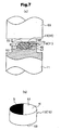
- Fig. 7A shows a step of magnetizing the magnet 13 of the driven gear 9 by a magnetizing apparatus and Fig. 7B shows the magnet 13 after having been magnetized. Further, the magnetizing step is similar to that of the magnet 15 of the driven gear 11, the magnet 13 of the driven gear 9 will mainly be explained and correspondence of the magnet 15 of the driven gear 11 will be shown by attaching a bracket.
- the magnetizing apparatus of Fig. 7A is provided with a magnetic pole 69 for magnetizing and a jig 71.
- the jig 71 is formed with a recess portion 73.
- a magnetic body in a cylindrical face before being magnetized constituting a base member of the magnet 13 is formed by injection molding of plastic base.
- Injection molding of the plastic base signifies that a resin of nylon, PPS or the like is mixed with a magnetic powder and the magnetic body before being magnetized is formed in a cylindrical shape by injection molding.
- a blend ratio of the resin and the magnetic powder can variously be selected.
- the magnetic powder for example, a neodymium alloy, a samarium-cobalt alloy or the like is used.
- the magnetic body in the cylindrical shape is provided at a rotational center portion of the driven gear 9 by subjecting the resin to insert molding.
- the plane portion 51 of the magnetic body is magnetized between the magnetic hole 69 and the jig 71 of Fig. 7A .
- the fitting boss portion 49 of the driven gear 9 is fittedly supported by the recess portion 73 of the jig 71.
- centers of the magnetic pole 69 and the jig 71 and a rotational center of the driven gear 9 are aligned.
- N-S poles are magnetized at the plane portion 51 of the magnetic body with the rotational center of the driven gear 9 as a reference and the N pole and the S pole are accurately formed at the plane portion 51 of the magnet 13 with the rotational center as a boundary as shown by Fig. 7B .
- the plane portions 51 and 53 which are upper and lower faces of the magnetic body are projected from the faces 55 and 57 of the driven gear 9, the plane portions 51 and 53 can firmly be brought into close contact with faces of the magnetic pole 69 and the jig 71 and the magnetizing by the magnetic pole 69 can efficiently be carried out. Further, even when the plane portions 51 and 53 are flush with the faces 55 and 57 of the driven gear 9, a similar effect can be achieved.
- the case 5 is attached to a base of a combination switch or the like, the engaging claw 47 is engaged with the side of the steering wheel and the drive gear 7 can be rotated cooperatively with the side of the steering wheel which is the object to be detected.
- the driven gears 9 and 11 which are brought in mesh with the drive gear 7 are cooperatively rotated.
- the magnets 13 and 15 are rotated and the magnetic fields of the magnetic reluctance elements 63 opposed thereto are changed and the reluctance value of the magnetic reluctance element 63 is changed in accordance with the change.
- the change of the reluctance value is converted into an angle signal by the electronic circuit part 19 and outputted as the angle signal to an external system via the connector 65. Therefore, a rotational angle of the object to be detected of the steering wheel or the like can accurately be detected.
- the driven gears 9 and 11 are rotatably interposed by the driven gear supporting portions 39 and 41 of the case 5 and the projected portions 23 of the cover 3, a constant distance is maintained between the plane portion 51 of each of the magnets 13 and 15 and the magnetic reluctance element 63 of the circuit board 17, the circuit board 17 and the driven gears 9 and 11 are not brought in direct contact with each other and therefore, vibration or the like at the circuit board 17 in accordance with rotation of the driven gears 9 and 11 is restrained from being brought about. The effect is further promoted when the respective projected portions 23 are brought into a loosely fitted state with the through holes 59 and 61 of the circuit board 17.
- the drive gear 7 is provided with two pieces of the driven gears 9 and 11 having the same teeth number and two of the magnetic reluctance elements 63 in correspondence therewith and therefore, when a difference between respective detection angles is equal to or larger than a prescribed amount by detection by the respective magnets 13 and 15 of the respective driven gears 9 and 11 and the respective magnetic reluctance elements 63, the apparatus can be determined to be failed and a failure signal can be outputted.
- the cover 3, the case 5, the drive gear 7 and the driven gears 9 and 11 are formed by resin materials having substantially the same linear expansion coefficient and therefore, even when temperature is changed as in high temperature or low temperature, influence is restrained from effecting on a relative relationship among the case 5, the cover 3, the drive gear 7 and the driven gears 9 and 11 and detection accuracy equivalent to that in normal temperature can be ensured.
- Fig. 8 through Fig. 14 shows a second embodiment of the invention.
- Fig. 8 is a sectional view of a rotation detecting apparatus according to the second embodiment
- Fig. 9 is a sectional view enlarging an essential portion thereof
- Fig. 10 is a perspective plane view viewed from a side of the cover
- Fig. 11 is a perspective bottom view viewed from a side opposed to the cover
- Fig. 12 is a side view
- Fig. 13 is a plane view
- Fig. 14 is a bottom view.
- the embodiment is basically similar to the first embodiment and an explanation will be given thereof by attaching the same notations to corresponding constituent portions.
- the drive gear and the driven gear are respectively provided with ring portions 73 and 75.
- outer diameters thereof are formed by diameters in correspondence with respective pitch circles of a drive gear 69 and a driven gear 71.
- the drive gear 69 and the driven gear 71 as well as the respective ring portions 73 and 75 are formed by elastic bodies, for example, elastomer.
- elastic bodies for example, elastomer.
- the case 5 is provided with engaging pins 77 at both sides of the driven gear 71. Respective end portions of a leaf spring 79 are engaged with and supported by the respective engaging pins 77. The leaf spring 79 is brought into elastic contact with the ring portion 75 of the driven gear 71.
- the driven gear 71 is brought into a state of being urged to a side of the drive gear 73.
- the ring portion 73 of the drive gear 69 and the ring portion 75 of the driven gear 71 are brought into elastic contact with each other by a press force to generate pertinent friction force.
- the ring portions 73 and 75 it is also possible to arrange the ring portions 73 and 75 to be brought into elastic contact with each other by the press force to generate the pertinent friction force by omitting the leaf spring 79. That is, when rotating shafts of the drive gear 69 and the driven gear 71 are rotatably supported by the case 5 at fixed positions to thereby bring the ring portions 73 and 75 into elastic contact with each other, the leaf spring 79 can be omitted.
- the driven gear 71 is rotated by friction force between the ring portion 73 of the drive gear 69 and the ring portion 75 of the driven gear 71.
- the press force of the leaf spring 79 generates pertinent friction force between the ring portions 73 and 75.
- At least either one of the ring portions 73 and 75 can be formed separately from the drive gear 69 or the driven gear 71.
- Fig. 15 and Fig. 16 show an embodiment of such a modified example
- Fig. 15 is a front view constituting a section by a portion of a driven gear 81
- Fig. 16 is a plane view thereof.
- a ring portion 83 is separately formed and attached fittedly to a boss portion 85 of the driven gear 81.
- the attachment can be fixed by press-fitting, adhesion or the like.
- the ring portion 83 is formed by, for example, an elastic body of elastomer or the like similar to the above-described.
- the rotational angle of the steering wheel as the object to be detected is detected, a constitution of detecting a rotational angle of other rotating body can also be constructed.
- the project portion 23 may be able to interpose rotatably the driven gear 9, 11, 71 or 81 and further stable support can be carried out thereby by providing a length to some degree in the peripheral direction.
- the magnetic body in the cylindrical shape before being magnetized for forming the magnet 13 or 15 is provided at the driven gear 9, 11, 71 or 81 by insert molding, there can also be constructed a constitution in which the magnetic body before being magnetized is fixed to the driven gear 9, 11, 71 or 81 by adherence or the like and the magnetic body is magnetized with the rotational center of the driven gear 9, 11, 71 or 81 as the reference thereafter.
- the magnet 13 or 15 is for generating a uniform magnetic field in a constant direction at the magnetic reluctance element 63 by rotation and is not limited to the cylindrical shape but may be formed in a rectangular parallelepiped or the like so far as the similar function is achieved.
- the magnet 13 or 15 which is sintered can also be subjected to insert molding or the like with the driven gear 9, 11, 71 or 81.
- the case 5, the cover 3, the drive gear 7, 69 and the driven gear 9 can also be formed by resin materials having different linear expansion coefficients and can also be formed by a material other than the resin.
- the teeth number m of the drive gear 7 and the teeth number n of the driven gear 9 or 11 can arbitrarily be selected other than the above-described.
Description
- The present invention relates to a rotation detecting apparatus provided for detecting a rotational angle of a steering wheel of an automobile or the like.
- There is a conventional rotation detecting apparatus described in, for example,
JP-A-2000-283704 Fig. 17. Fig. 17 shows a rotation detecting apparatus integrated to arotational connector apparatus 101 for electrically connecting a vehicle body side thereof and a steering wheel side thereof. That is, arotation detecting apparatus 107 is provided between alower housing member 103 and alower cover member 105 of therotational connector apparatus 101. Therotation detecting apparatus 107 is generally constituted by adrive gear 109, a drivengear 111, and acircuit board 113. - The
drive gear 109 is constructed by a constitution of being cooperatively rotated in accordance with rotation of the steering wheel. The drivengear 111 is brought in mesh with thedrive gear 109. The drivengear 111 is provided with amagnet 115 at a rotational center portion thereof. Themagnet 115 includes aplane portion 117. Theplane portion 117 is contiguously formed with an N pole and an S pole with a rotational center of the drivengear 111 as a boundary. The drivengear 111 is constructed by a constitution in which one face side thereof is rotatably supported by thecover member 105 and other face side thereof is brought into sliding contact with thecircuit board 113. Thecircuit board 113 is provided with amagnetic reluctance element 119 opposed to theplane portion 117 of themagnet 115. - Further, when the
drive gear 109 is rotated in accordance with steering of the steering wheel, the drivengear 111 is rotated cooperatively therewith. When themagnet 115 is rotated by rotating the drivengear 111, a magnetic field of themagnetic reluctance element 119 opposed to theplane portion 117 formed with the N pole and the S pole is changed and a reluctance value of themagnetic reluctance element 119 is changed in accordance with the change. An angle signal can be outputted to an external system by converting the change into the angle signal by an electronic circuit portion. - Therefore, a steering angle of the steering wheel or the like can accurately be detected without restricting an angle detecting range.
- However, according to the above-described structure, one side face of the driven
gear 111 is directly brought into sliding contact with thecircuit board 113 and therefore, when the drivengear 111 is rotated, vibration or the like is brought about at thecircuit board 113. Therefore, there is a concern of effecting adverse influence by the vibration on a soldered portion of a circuit element mounted to thecircuit board 113 or themagnetic reluctance element 119 per se and there is a concern of deteriorating durability and detection accuracy of the apparatus. -
DE-A-199 29 200 describes a rotation detection apparatus comprising a drive gear, a driven gear, a magnet, a circuit board and a magnet reluctance element attached to the circuit board. Moreover, the rotation detection apparatus comprises a case consisting of an upper and lower part. The driven gear of the rotation detection apparatus is rotatably interposed by the upper part and the lower part of the case. -
US-A-5,055,781 also describes an apparatus for detecting a rotational angle of a rotating shaft comprising a magneto member and a detecting element which are arranged such that one of the detecting element and the magneto member is mounted on the rotating shaft. - It is an object of the invention to provide a rotation detecting apparatus capable of promoting durability and promoting detection accuracy of the apparatus by restraining vibration or the like from being brought about on a side of a circuit board when a driven gear is rotated.
- According to a first aspect of the invention, when the drive gear rotatably supported by the case having the cover is rotated cooperatively with the object to be detected, the driven gear brought in mesh with the drive gear can be rotated cooperatively therewith. The driven gear is provided with the magnet having the end face portion contiguously formed with the N pole and the S pole at the rotational center portion and the magnet can be rotated along with the driven gear. The case is arranged with the circuit board, the circuit board is provided with the magnetic reluctance element opposed to the end face portion of the magnet, a magnetic field of the magnetic reluctance element is changed by rotating the magnet, the reluctance value of the magnetic reluctance element is changed in accordance with the change and a signal can be outputted. The output signal of the magnetic reluctance element is converted into the rotational angle signal by the electronic circuit part provided to the circuit board and can be outputted to an external system as an angle signal.
- Further, the driven gear is rotatably interposed by the case and the cover, the constant distance is maintained between the end face portion of the magnet and the magnetic reluctance element and therefore, when the driven gear is rotated, the driven gear is rotatably supported by the case and the cover and vibration or the like can be restrained from being brought about at the circuit board. Therefore, adverse influence by vibration can be restrained from effecting on a soldered portion of a circuit element and the magnetic reluctance element mounted to the circuit board, durability of the apparatus is promoted, and rotation can be detected accurately.
- According to a second aspect of the invention, in addition to an effect of the first aspect of the invention, since the case, the cover, the drive gear and the driven gear are formed by materials having substantially the same linear expansion coefficient, even when temperature is changed to high temperature or low temperature, an influence is restrained from effecting on a relative relationship among the case, the cover, the drive gear and the driven gear and the detection accuracy equivalent to that at normal temperature can be ensured.
-
-
Fig. 1 is a disassembled perspective view of a rotation detecting apparatus according to a first embodiment of the invention; -
Fig. 2 is a sectional view of the rotation detecting apparatus according to the first embodiment; -
Fig. 3 is a sectional view enlarging an essential portion according to the first embodiment; -
Fig. 4 is a front view constituting a section by a portion of a driven gear according to the first embodiment; -
Fig. 5 is a plane view of the driven gear according to the first embodiment; -
Fig. 6 is a bottom view of the driven gear according to the first embodiment; -
Fig. 7A is an explanatory view showing a magnetizing step andFig. 7B is a perspective view of a magnet after having been magnetized according to the first embodiment; -
Fig. 8 is a sectional view of a rotation detecting apparatus according to a second embodiment of the invention; -
Fig. 9 is a sectional view enlarging an essential portion according to the second embodiment; -
Fig. 10 is a perspective plane view viewed from a side of a cover according to the second embodiment; -
Fig. 11 is a perspective bottom view viewed from a side opposed to the cover according to the second embodiment; -
Fig. 12 is a side view of the rotation detecting apparatus according to the second embodiment; -
Fig. 13 is a plane view of the rotation detecting apparatus according to the second embodiment; -
Fig. 14 is a bottom view of the rotation detecting apparatus according to the second embodiment; -
Fig. 15 shows an embodiment according to a modified example of a driven gear of the second embodiment and is a front view constituting a section by a portion thereof; -
Fig. 16 relates to an embodiment according to the modified example of the driven gear of the second embodiment and is a plane view thereof; and -
Fig. 17 is a sectional view of a rotation detecting apparatus according to a conventional example. -
Fig. 1 is a disassembled perspective view of a rotation detecting apparatus according to a first embodiment of the invention andFig. 2 shows a sectional view of the rotation detecting apparatus. As shown byFig. 1 andFig. 2 , according to arotation detecting apparatus 1, adrive gear 7 is rotatably supported by acase 5 having acover 3. A pair of drivengears 9 and 11 are rotatably supported between thecover 3 and thecase 5. The respective drivengears 9 and 11 are brought in mesh with thedrive gear 7.Magnets gears 9 and 11. - The
cover 3, thecase 5, thedrive gear 7, and the drivengears 9 and 11 are formed by resin materials having substantially the same linear expansion coefficient. - A number of teeth m of the
drive gear 7 and a number of teeth n of the drivengear 9 or 11 are set to dividable values such that a value of n/m becomes a finite terminating decimal. Therefore, an error by rounding a numerical value is not brought about, operation at anelectronic circuit part 19 can be simplified and accuracy thereof can be promoted. - The
case 5 is arranged with acircuit board 17 connectable to outside. Thecircuit board 17 is attached with amagnetic reluctance element 63 and theelectronic circuit part 19 for converting an output signal of themagnetic reluctance element 63 into a rotational angle signal. - A further explanation will be given here of details of respective portions also in reference to
Fig. 3 through Fig. 6 .Fig. 3 is a sectional view enlarging an essential portion of therotation detecting apparatus 1,Fig. 4 is a front view constituting a section by a portion of the driven gear,Fig. 5 is a plane view of the driven gear, andFig. 6 is a bottom view of the driven gear. - First, as shown by
Fig. 1 ,Fig. 2 and Fig. 3 , thecover 3 is provided with asupport hole 21 for rotatably supporting to fit a side of thedrive gear 7 at a central portion thereof. Thecover 3 is provided with projectedportions 23 respectively in correspondence with the respective drivengears 9 and 11. For example, four pieces of the projectedportions 23 are provided for each of the respective drivengear 9 and 11 and uniformly arranged in peripheral directions centering on rotational centers of the respective drivengears 9 and 11. Thecover 3 is fixedly fastened to thecase 5 along with thecircuit board 17 by, for example, four pieces of tapping screws 25. - The
case 5 is provided with asupport hole 27 for rotatably supporting thedrive gear 7. At a surrounding of thesupport hole 27, there is provided aperipheral wall portion 29 for surrounding an outer periphery of thedrive gear 7 with a clearance therebetween. Theperipheral wall portion 29 is continuous withwall portions gears 9 and 11.Wall portions wall portions gear 9 is surrounded by thewall portions wall portions gear supporting portions wall portions wall portions case 5 is provided with afitting recess portion 40 at an inner peripheral face thereof on a side of thecover 3. - The
drive gear 7 is projected withfitting boss portions fitting boss portion 43 on one side is projected with a pair of engagingclaws 47. The engagingclaw 47 is constructed by a constitution of engaging with a side of the steering wheel which is an object to be detected and rotating thedrive gear 7 cooperatively with rotation on the side of the steering wheel. - The driven gears 9 and 11 will be explained also in reference to
Fig. 4 through Fig. 6 . The explanation will be given of the drivengear 9 since the drivengears 9 and 11 are constituted by the same structure. The drivengear 9 includes afitting boss portion 49. Themagnet 13 is concentrically provided at the rotational center portion of the drivengear 9. Themagnet 13 is formed in a cylindrical shape and is subjected to insert molding with the drivengear 9. - The
magnet 13 includesplane portions plane portions gear 13. However, theplane portions faces - The
plane portion 51 is formed with an N pole and an S pole contiguously with the rotational center as a boundary. Theplane portion 51 is magnetized with N-S with the rotational center of the drivengear 7 as a reference after subjecting a magnetic body before being magnetized in a cylindrical shape formed by the injection molding to insert molding with the drivengear 7. - The
circuit board 17 is provided with pluralities of throughholes 59 and 61 at positions respectively in correspondence with the drivengear supporting portions portions 23 of thecover 3. Thecircuit board 17 is respectively provided with themagnetic reluctance elements 63 opposed to theplane portions 51 of themagnets gear supporting portions circuit board 17 is provided with aconnector 65. Theconnector 65 is made connectable to outside and is fixed to thecircuit board 17 by, for example, a tappingscrew 67. However, theconnector 65 can also be connected to the side of thecase 5 by a tapping screw. - The
electronic circuit part 19, themagnetic reluctance element 63 and theconnector 65 constitute a circuit above thecircuit board 17. - Further, the
fitting boss portion 45 of thedrive gear 7 is fittedly supported by the drivegear supporting hole 27 of thecase 5. The driven gears 9 and 11 are respectively supported by the drivengear supporting portions fitting boss portions 49 of the drivengears 9 and 11 to the drivengear supporting portions - The
circuit board 17 is fitted to thecase 5 and an outerperipheral portion 17a thereof is fittedly supported by thefitting recess portion 41 of thecase 5. Thecover 3 is fitted to thecase 5 and an outerperipheral portion 3a of thecover 3 is fittedly supported by thefitting recess portion 40 of thecover 3. The respective projectedportions 23 of thecover 3 respectively penetrate the throughholes 59 and 61 and front ends thereof are respectively opposed to the drivengears 9 and 11. - The
case 5 and thecover 3 are fixedly fastened by the tapping screws 25. Thereby, there is constructed a constitution in which the drivengears 9 and 11 are rotatably interposed by the drivengear supporting portions portions 23 and the drivengears 9 and 11 are rotatably interposed by thecase 5 and thecover 3. That is, the drivengears 9 and 11 are rotatable around rotational centers thereof in the interposed state. - In a state in which the driven
gears 9 and 11 are supported as described above, a constant distance is maintained between theplane portions 51 of themagnets magnetic reluctance elements 63 with thecase 5 as a reference. -
Fig. 7A shows a step of magnetizing themagnet 13 of the drivengear 9 by a magnetizing apparatus andFig. 7B shows themagnet 13 after having been magnetized. Further, the magnetizing step is similar to that of themagnet 15 of the driven gear 11, themagnet 13 of the drivengear 9 will mainly be explained and correspondence of themagnet 15 of the driven gear 11 will be shown by attaching a bracket. - The magnetizing apparatus of
Fig. 7A is provided with amagnetic pole 69 for magnetizing and ajig 71. Thejig 71 is formed with arecess portion 73. - In fabricating the driven
gear 9 having themagnet 13, a magnetic body in a cylindrical face before being magnetized constituting a base member of the magnet 13 (magnet 13 before being magnetized) is formed by injection molding of plastic base. Injection molding of the plastic base signifies that a resin of nylon, PPS or the like is mixed with a magnetic powder and the magnetic body before being magnetized is formed in a cylindrical shape by injection molding. A blend ratio of the resin and the magnetic powder can variously be selected. As the magnetic powder, for example, a neodymium alloy, a samarium-cobalt alloy or the like is used. - The magnetic body in the cylindrical shape is provided at a rotational center portion of the driven
gear 9 by subjecting the resin to insert molding. - Thereafter, the
plane portion 51 of the magnetic body is magnetized between themagnetic hole 69 and thejig 71 ofFig. 7A . In this case, thefitting boss portion 49 of the drivengear 9 is fittedly supported by therecess portion 73 of thejig 71. By the support, centers of themagnetic pole 69 and thejig 71 and a rotational center of the drivengear 9 are aligned. Under the state, N-S poles are magnetized at theplane portion 51 of the magnetic body with the rotational center of the drivengear 9 as a reference and the N pole and the S pole are accurately formed at theplane portion 51 of themagnet 13 with the rotational center as a boundary as shown byFig. 7B . - In the magnetizing, since the
plane portions faces gear 9, theplane portions magnetic pole 69 and thejig 71 and the magnetizing by themagnetic pole 69 can efficiently be carried out. Further, even when theplane portions faces gear 9, a similar effect can be achieved. - In the above-described rotation detecting apparatus, the
case 5 is attached to a base of a combination switch or the like, the engagingclaw 47 is engaged with the side of the steering wheel and thedrive gear 7 can be rotated cooperatively with the side of the steering wheel which is the object to be detected. - When the
drive gear 7 is rotated in accordance with steering of the steering wheel, the drivengears 9 and 11 which are brought in mesh with thedrive gear 7 are cooperatively rotated. By rotating the drivengears 9 and 11, themagnets magnetic reluctance elements 63 opposed thereto are changed and the reluctance value of themagnetic reluctance element 63 is changed in accordance with the change. - The change of the reluctance value is converted into an angle signal by the
electronic circuit part 19 and outputted as the angle signal to an external system via theconnector 65. Therefore, a rotational angle of the object to be detected of the steering wheel or the like can accurately be detected. - According to the embodiment, particularly, the driven
gears 9 and 11 are rotatably interposed by the drivengear supporting portions case 5 and the projectedportions 23 of thecover 3, a constant distance is maintained between theplane portion 51 of each of themagnets magnetic reluctance element 63 of thecircuit board 17, thecircuit board 17 and the drivengears 9 and 11 are not brought in direct contact with each other and therefore, vibration or the like at thecircuit board 17 in accordance with rotation of the drivengears 9 and 11 is restrained from being brought about. The effect is further promoted when the respective projectedportions 23 are brought into a loosely fitted state with the throughholes 59 and 61 of thecircuit board 17. - Therefore, adverse influence by vibration is restrained from being effected on the
magnetic reluctance element 63 and the rotational angle can accurately be detected. Further, also adverse influence on a soldered portion of a circuit element mounted to thecircuit board 17 is restrained and durability can significantly be promoted. - According to the embodiment, the
drive gear 7 is provided with two pieces of the drivengears 9 and 11 having the same teeth number and two of themagnetic reluctance elements 63 in correspondence therewith and therefore, when a difference between respective detection angles is equal to or larger than a prescribed amount by detection by therespective magnets gears 9 and 11 and the respectivemagnetic reluctance elements 63, the apparatus can be determined to be failed and a failure signal can be outputted. - The
cover 3, thecase 5, thedrive gear 7 and the drivengears 9 and 11 are formed by resin materials having substantially the same linear expansion coefficient and therefore, even when temperature is changed as in high temperature or low temperature, influence is restrained from effecting on a relative relationship among thecase 5, thecover 3, thedrive gear 7 and the drivengears 9 and 11 and detection accuracy equivalent to that in normal temperature can be ensured. -
Fig. 8 through Fig. 14 shows a second embodiment of the invention.Fig. 8 is a sectional view of a rotation detecting apparatus according to the second embodiment,Fig. 9 is a sectional view enlarging an essential portion thereof,Fig. 10 is a perspective plane view viewed from a side of the cover,Fig. 11 is a perspective bottom view viewed from a side opposed to the cover,Fig. 12 is a side view,Fig. 13 is a plane view andFig. 14 is a bottom view. Further, also the embodiment is basically similar to the first embodiment and an explanation will be given thereof by attaching the same notations to corresponding constituent portions. - According to a
rotation detecting apparatus 1A of the embodiment, as shown byFig. 8 through Fig. 14 , the drive gear and the driven gear are respectively provided withring portions ring portions drive gear 69 and a drivengear 71. - According to the embodiment, the
drive gear 69 and the drivengear 71 as well as therespective ring portions drive gear 69 and the drivengear 71 by an elastic body of elastomer or the like and constitute only one of thering portions - As shown by
Fig. 10 and Fig. 11 , thecase 5 is provided with engagingpins 77 at both sides of the drivengear 71. Respective end portions of aleaf spring 79 are engaged with and supported by the respective engaging pins 77. Theleaf spring 79 is brought into elastic contact with thering portion 75 of the drivengear 71. - Therefore, the driven
gear 71 is brought into a state of being urged to a side of thedrive gear 73. Thereby, thering portion 73 of thedrive gear 69 and thering portion 75 of the drivengear 71 are brought into elastic contact with each other by a press force to generate pertinent friction force. - However, it is also possible to arrange the
ring portions leaf spring 79. That is, when rotating shafts of thedrive gear 69 and the drivengear 71 are rotatably supported by thecase 5 at fixed positions to thereby bring thering portions leaf spring 79 can be omitted. - When the
drive gear 69 is rotated, the drivengear 71 in mesh therewith is driven by light load of substantially sliding resistance against thecase 5 and thecover 3 and mesh resistance between thedrive gear 69 and the drivengear 71. - Further, when the
drive gear 69 is rotated cooperatively with, for example, a steering wheel which is an object to be detected, the drivengear 71 is rotated by friction force between thering portion 73 of thedrive gear 69 and thering portion 75 of the drivengear 71. At this occasion, the press force of theleaf spring 79 generates pertinent friction force between thering portions - Therefore, even when there is a backlash between a
teeth portion 69a of thedrive gear 69 and ateeth portion 71a of the drivengear 71, thering portions - Even when slippage is generated between the
ring portions gear 71, a shift equal to or larger than the backlash is not brought about by bringing theteeth portions - Further, at least either one of the
ring portions drive gear 69 or the drivengear 71. -
Fig. 15 andFig. 16 show an embodiment of such a modified example,Fig. 15 is a front view constituting a section by a portion of a drivengear 81 andFig. 16 is a plane view thereof. As shown byFig. 15 andFig. 16 , aring portion 83 is separately formed and attached fittedly to aboss portion 85 of the drivengear 81. The attachment can be fixed by press-fitting, adhesion or the like. Thering portion 83 is formed by, for example, an elastic body of elastomer or the like similar to the above-described. - Therefore, a function similar to that of the
ring portion 75 can be achieved also by thering portion 83. - Further, in the case of
Fig. 15 andFig. 16 , when thering portion 83 is worn, only thering portion 83 can pertinently be interchanged and the maintenance cost can be reduced. - Further, although according to the embodiment, the rotational angle of the steering wheel as the object to be detected is detected, a constitution of detecting a rotational angle of other rotating body can also be constructed.
- The
project portion 23 may be able to interpose rotatably the drivengear - Although the magnetic body in the cylindrical shape before being magnetized for forming the
magnet gear gear gear - It is also possible to fix the
magnet gears magnet gear - In either of the embodiment of constituting the
magnet gear magnet gear magnet gear magnetic reluctance element 63 without forming themagnet gear - The
magnet magnetic reluctance element 63 by rotation and is not limited to the cylindrical shape but may be formed in a rectangular parallelepiped or the like so far as the similar function is achieved. - Other than injection molding of plastic base, the
magnet gear - The
case 5, thecover 3, thedrive gear gear 9 can also be formed by resin materials having different linear expansion coefficients and can also be formed by a material other than the resin. - The teeth number m of the
drive gear 7 and the teeth number n of the drivengear 9 or 11 can arbitrarily be selected other than the above-described.
Claims (2)
- A rotation detecting apparatus comprising:a case (5) having a cover (3);a driver gear (7) rotatably supported by the case (5) and capable of rotating cooperatively with an object to be detected;a driven gear (9, 11) brought in mesh with the drive gear (7) and capable of rotating cooperatively therewith;a magnet (13, 15) provided at a rotational center portion of the driven gear (9, 11) andhaving an end face portion (51, 53) contiguously formed with an N pole and an S pole;a circuit board (17) arranged in the case (5);a magnetic reluctance element (63) attached to the circuit board (17) and being opposed to the end face portion of the magnet (13, 15);and an electronic circuit part (19) for converting an output signal of the magnetic reluctance element (63) into a rotational angle signal;characterized inthat the cover (3) is provided with projected portions (23) and the circuit board (17) is provided with through holes (59, 61) at positions in correspondence with the driven gear (9, 11) supporting portion (39,41), the projected portions (23) of the cover (3) penetrating the through holes (59, 61) of the circuit board (17), the front ends of the projected portions (23) opposing the driven gear (9, 11); andthe driven gear (9, 11) is rotatably interposed by the projected portions (23) of the cover (3) and the case (5) and is rotatably interposed by the driven gear supporting portion (39, 41) of the case (5) and the projected portions (23) of the cover (3) so that a constant distance is maintained between the end face portion (51, 53) of the magnet (13, 15) and the magnetic reluctance element (63) with the case (5) as a reference.
- The rotation detecting apparatus according to claim 1, wherein the case (5), the cover (3), the drive gear (7) and the driven gear (9, 11) consist of materials having substantially the same linear expansion coefficient.
Applications Claiming Priority (2)
| Application Number | Priority Date | Filing Date | Title |
|---|---|---|---|
| JP2002153760A JP3958115B2 (en) | 2002-05-28 | 2002-05-28 | Rotation detector |
| JP2002153760 | 2002-05-28 |
Publications (2)
| Publication Number | Publication Date |
|---|---|
| EP1367360A1 EP1367360A1 (en) | 2003-12-03 |
| EP1367360B1 true EP1367360B1 (en) | 2012-07-04 |
Family
ID=29417168
Family Applications (1)
| Application Number | Title | Priority Date | Filing Date |
|---|---|---|---|
| EP03011798A Expired - Fee Related EP1367360B1 (en) | 2002-05-28 | 2003-05-24 | Rotation detecting apparatus |
Country Status (4)
| Country | Link |
|---|---|
| US (1) | US6784661B2 (en) |
| EP (1) | EP1367360B1 (en) |
| JP (1) | JP3958115B2 (en) |
| KR (1) | KR100918342B1 (en) |
Families Citing this family (15)
| Publication number | Priority date | Publication date | Assignee | Title |
|---|---|---|---|---|
| FR2858509B1 (en) | 2003-07-28 | 2005-10-14 | Citilog | METHOD FOR CALIBRATING AT LEAST TWO VIDEO CAMERAS RELATIVE TO THE OTHER FOR STEROSCOPIC VIEWING AND DEVICE FOR PERFORMING THE METHOD |
| JP2005257471A (en) * | 2004-03-11 | 2005-09-22 | Yazaki Corp | Rotation angle detection device |
| JP2007187480A (en) * | 2006-01-11 | 2007-07-26 | Jtekt Corp | Torque detector |
| JP2007192609A (en) * | 2006-01-18 | 2007-08-02 | Matsushita Electric Ind Co Ltd | Rotation angle detector |
| JP2008026039A (en) * | 2006-07-19 | 2008-02-07 | Matsushita Electric Ind Co Ltd | Rotational angle detector |
| US20100294603A1 (en) * | 2006-12-22 | 2010-11-25 | St Clair Kenneth A | Brake with field responsive material |
| JP5064315B2 (en) * | 2008-07-01 | 2012-10-31 | ナイルス株式会社 | Rotation angle sensor |
| DE102008063772A1 (en) * | 2008-12-22 | 2010-06-24 | Ipgate Ag | Rotation angle sensor for spindle drives of brake booster, for detecting rotational movement or position of body, particularly shaft, is provided with housings, in which sensor element is arranged for detecting rotational movement of magnet |
| JP2010286299A (en) * | 2009-06-10 | 2010-12-24 | Alps Electric Co Ltd | Rotation angle sensor |
| CN103188905B (en) * | 2011-12-27 | 2017-04-12 | 富泰华工业(深圳)有限公司 | Electronic device with an inlet and outlet mechanism |
| JP6375156B2 (en) * | 2014-06-25 | 2018-08-15 | Kyb株式会社 | Electric power steering device |
| WO2018230188A1 (en) * | 2017-06-15 | 2018-12-20 | アルプス電気株式会社 | Rotation detection device |
| JP6626476B2 (en) * | 2017-07-13 | 2019-12-25 | オリエンタルモーター株式会社 | Rotation angle detection device using gear support mechanism to hold gear in proper position |
| JP7192619B2 (en) * | 2019-03-29 | 2022-12-20 | 株式会社ジェイテクト | sensor device |
| US11846529B2 (en) | 2021-04-19 | 2023-12-19 | Joral Llc | Magnetic rack and pinion linear magnetic encoder and position sensing system |
Family Cites Families (7)
| Publication number | Priority date | Publication date | Assignee | Title |
|---|---|---|---|---|
| JPS6325877A (en) * | 1986-07-17 | 1988-02-03 | Victor Co Of Japan Ltd | Case for disk driving device |
| DE4014885C2 (en) * | 1989-05-13 | 1995-07-13 | Aisan Ind | Angle of rotation sensor |
| US5602472A (en) * | 1993-01-15 | 1997-02-11 | Hughes Electronics | Apparatus and method for determining angular position and rotational speed using a rotating magnet and a directional magnetometer |
| JPH11281351A (en) * | 1998-01-28 | 1999-10-15 | Fuji Electric Co Ltd | Distance measuring apparatus |
| US6646432B1 (en) * | 1998-11-04 | 2003-11-11 | Meritor Heavy Vehicle Systems, Llc | Electronic odometer integrated into vehicle axle and wheel hub |
| JP2000283704A (en) * | 1999-03-30 | 2000-10-13 | Bosch Braking Systems Co Ltd | Rotation detecting device |
| DE19929200A1 (en) * | 1999-06-25 | 2000-12-28 | Cherry Gmbh | Rotary selection switch system with magnetoresistive sensors has shaft whose rotation is transferred element mounted on different axis of rotation, on which permanent magnet is mounted |
-
2002
- 2002-05-28 JP JP2002153760A patent/JP3958115B2/en not_active Expired - Fee Related
-
2003
- 2003-05-24 EP EP03011798A patent/EP1367360B1/en not_active Expired - Fee Related
- 2003-05-27 KR KR1020030033578A patent/KR100918342B1/en active IP Right Grant
- 2003-05-27 US US10/445,261 patent/US6784661B2/en not_active Expired - Fee Related
Also Published As
| Publication number | Publication date |
|---|---|
| US6784661B2 (en) | 2004-08-31 |
| EP1367360A1 (en) | 2003-12-03 |
| KR100918342B1 (en) | 2009-09-22 |
| JP3958115B2 (en) | 2007-08-15 |
| JP2003344103A (en) | 2003-12-03 |
| US20030222644A1 (en) | 2003-12-04 |
| KR20030091807A (en) | 2003-12-03 |
Similar Documents
| Publication | Publication Date | Title |
|---|---|---|
| EP1367360B1 (en) | Rotation detecting apparatus | |
| US7019516B2 (en) | Magnetic sensor unit less responsive to leaking magnetic flux | |
| US20080003853A1 (en) | Rotary connector device equipped with built-in steering angle sensor | |
| US7932716B2 (en) | Rotation angle sensor and rotation angle sensor system | |
| US7049807B2 (en) | Rotation detection device with magnet magnetized after intergration with gear | |
| EP1426750A1 (en) | Torque detection device | |
| JP7316077B2 (en) | absolute encoder | |
| CN113631888A (en) | Speed reduction mechanism and absolute encoder | |
| JP2001254812A (en) | Inhibitor switch | |
| CN113167602A (en) | Absolute encoder | |
| US20220163317A1 (en) | Absolute encoder | |
| US6515472B2 (en) | Transmission selector sensor assembly package for integration into transmission assembly | |
| US5394081A (en) | Rotary pulse generator | |
| EP0909011B1 (en) | Connection structure of stepping motor | |
| JP2004170205A (en) | Rotation angle detecting device | |
| JPS6358264A (en) | Rotating direction detector | |
| JP2000283704A (en) | Rotation detecting device | |
| JP2020165783A (en) | Absolute encoder | |
| US6703828B2 (en) | Mechanical design for a sensor to prevent an ice lock condition | |
| US20220247277A1 (en) | Yoke member for torque detection device, torque detection device, and steering device | |
| US20210380161A1 (en) | Magnetic sensor, torque sensing device and steering apparatus | |
| CN210839241U (en) | Encoder and motor | |
| JP2021183952A (en) | Magnetic sensor,torque detection device, and steering device | |
| JP2022098153A (en) | Rotational angle sensor |
Legal Events
| Date | Code | Title | Description |
|---|---|---|---|
| PUAI | Public reference made under article 153(3) epc to a published international application that has entered the european phase |
Free format text: ORIGINAL CODE: 0009012 |
|
| AK | Designated contracting states |
Kind code of ref document: A1 Designated state(s): AT BE BG CH CY CZ DE DK EE ES FI FR GB GR HU IE IT LI LU MC NL PT RO SE SI SK TR |
|
| AX | Request for extension of the european patent |
Extension state: AL LT LV MK |
|
| 17P | Request for examination filed |
Effective date: 20040515 |
|
| AKX | Designation fees paid |
Designated state(s): DE FR GB |
|
| 17Q | First examination report despatched |
Effective date: 20071116 |
|
| REG | Reference to a national code |
Ref country code: DE Ref legal event code: R079 Ref document number: 60341435 Country of ref document: DE Free format text: PREVIOUS MAIN CLASS: G01B0007300000 Ipc: G01D0005040000 |
|
| GRAP | Despatch of communication of intention to grant a patent |
Free format text: ORIGINAL CODE: EPIDOSNIGR1 |
|
| RIC1 | Information provided on ipc code assigned before grant |
Ipc: G01D 11/24 20060101ALI20111215BHEP Ipc: G01D 5/04 20060101AFI20111215BHEP |
|
| GRAS | Grant fee paid |
Free format text: ORIGINAL CODE: EPIDOSNIGR3 |
|
| GRAA | (expected) grant |
Free format text: ORIGINAL CODE: 0009210 |
|
| AK | Designated contracting states |
Kind code of ref document: B1 Designated state(s): DE FR GB |
|
| REG | Reference to a national code |
Ref country code: GB Ref legal event code: FG4D |
|
| REG | Reference to a national code |
Ref country code: DE Ref legal event code: R096 Ref document number: 60341435 Country of ref document: DE Effective date: 20120830 |
|
| PLBE | No opposition filed within time limit |
Free format text: ORIGINAL CODE: 0009261 |
|
| STAA | Information on the status of an ep patent application or granted ep patent |
Free format text: STATUS: NO OPPOSITION FILED WITHIN TIME LIMIT |
|
| 26N | No opposition filed |
Effective date: 20130405 |
|
| REG | Reference to a national code |
Ref country code: DE Ref legal event code: R097 Ref document number: 60341435 Country of ref document: DE Effective date: 20130405 |
|
| PGFP | Annual fee paid to national office [announced via postgrant information from national office to epo] |
Ref country code: GB Payment date: 20140521 Year of fee payment: 12 |
|
| PGFP | Annual fee paid to national office [announced via postgrant information from national office to epo] |
Ref country code: DE Payment date: 20140521 Year of fee payment: 12 Ref country code: FR Payment date: 20140509 Year of fee payment: 12 |
|
| REG | Reference to a national code |
Ref country code: DE Ref legal event code: R119 Ref document number: 60341435 Country of ref document: DE |
|
| GBPC | Gb: european patent ceased through non-payment of renewal fee |
Effective date: 20150524 |
|
| REG | Reference to a national code |
Ref country code: FR Ref legal event code: ST Effective date: 20160129 |
|
| PG25 | Lapsed in a contracting state [announced via postgrant information from national office to epo] |
Ref country code: DE Free format text: LAPSE BECAUSE OF NON-PAYMENT OF DUE FEES Effective date: 20151201 Ref country code: GB Free format text: LAPSE BECAUSE OF NON-PAYMENT OF DUE FEES Effective date: 20150524 |
|
| PG25 | Lapsed in a contracting state [announced via postgrant information from national office to epo] |
Ref country code: FR Free format text: LAPSE BECAUSE OF NON-PAYMENT OF DUE FEES Effective date: 20150601 |