EP1367356B1 - Amorce de sécurité - Google Patents
Amorce de sécurité Download PDFInfo
- Publication number
- EP1367356B1 EP1367356B1 EP03291268A EP03291268A EP1367356B1 EP 1367356 B1 EP1367356 B1 EP 1367356B1 EP 03291268 A EP03291268 A EP 03291268A EP 03291268 A EP03291268 A EP 03291268A EP 1367356 B1 EP1367356 B1 EP 1367356B1
- Authority
- EP
- European Patent Office
- Prior art keywords
- component according
- layer
- priming component
- safe priming
- mass
- Prior art date
- Legal status (The legal status is an assumption and is not a legal conclusion. Google has not performed a legal analysis and makes no representation as to the accuracy of the status listed.)
- Expired - Lifetime
Links
- 239000003999 initiator Substances 0.000 title description 4
- 239000000463 material Substances 0.000 claims abstract description 59
- -1 polytetrafluorethylene Polymers 0.000 claims description 53
- 239000004020 conductor Substances 0.000 claims description 38
- 230000037452 priming Effects 0.000 claims description 33
- 229920001577 copolymer Polymers 0.000 claims description 31
- 229920001343 polytetrafluoroethylene Polymers 0.000 claims description 29
- XAGFODPZIPBFFR-UHFFFAOYSA-N aluminium Chemical compound [Al] XAGFODPZIPBFFR-UHFFFAOYSA-N 0.000 claims description 28
- FYYHWMGAXLPEAU-UHFFFAOYSA-N Magnesium Chemical compound [Mg] FYYHWMGAXLPEAU-UHFFFAOYSA-N 0.000 claims description 27
- 239000000203 mixture Substances 0.000 claims description 24
- 229910052782 aluminium Inorganic materials 0.000 claims description 23
- 239000008188 pellet Substances 0.000 claims description 22
- 230000002093 peripheral effect Effects 0.000 claims description 20
- 239000011777 magnesium Substances 0.000 claims description 17
- 229910052749 magnesium Inorganic materials 0.000 claims description 17
- 229910052751 metal Inorganic materials 0.000 claims description 12
- 239000002184 metal Substances 0.000 claims description 12
- 239000011810 insulating material Substances 0.000 claims description 11
- 229920001220 nitrocellulos Polymers 0.000 claims description 9
- PXHVJJICTQNCMI-UHFFFAOYSA-N nickel Substances [Ni] PXHVJJICTQNCMI-UHFFFAOYSA-N 0.000 claims description 8
- 229920002492 poly(sulfone) Polymers 0.000 claims description 8
- FGIUAXJPYTZDNR-UHFFFAOYSA-N potassium nitrate Chemical compound [K+].[O-][N+]([O-])=O FGIUAXJPYTZDNR-UHFFFAOYSA-N 0.000 claims description 8
- QPLDLSVMHZLSFG-UHFFFAOYSA-N Copper oxide Chemical compound [Cu]=O QPLDLSVMHZLSFG-UHFFFAOYSA-N 0.000 claims description 7
- 239000005751 Copper oxide Substances 0.000 claims description 7
- 239000000020 Nitrocellulose Substances 0.000 claims description 7
- 229910000431 copper oxide Inorganic materials 0.000 claims description 7
- 229920001004 polyvinyl nitrate Polymers 0.000 claims description 7
- 239000002033 PVDF binder Substances 0.000 claims description 6
- 229930040373 Paraformaldehyde Natural products 0.000 claims description 6
- 229920006324 polyoxymethylene Polymers 0.000 claims description 6
- 239000004800 polyvinyl chloride Substances 0.000 claims description 6
- 229920002981 polyvinylidene fluoride Polymers 0.000 claims description 6
- OKTJSMMVPCPJKN-UHFFFAOYSA-N Carbon Chemical compound [C] OKTJSMMVPCPJKN-UHFFFAOYSA-N 0.000 claims description 5
- 239000008240 homogeneous mixture Substances 0.000 claims description 5
- 229920000915 polyvinyl chloride Polymers 0.000 claims description 5
- ZOXJGFHDIHLPTG-UHFFFAOYSA-N Boron Chemical compound [B] ZOXJGFHDIHLPTG-UHFFFAOYSA-N 0.000 claims description 4
- BQCADISMDOOEFD-UHFFFAOYSA-N Silver Chemical compound [Ag] BQCADISMDOOEFD-UHFFFAOYSA-N 0.000 claims description 4
- 229910052796 boron Inorganic materials 0.000 claims description 4
- 229910052799 carbon Inorganic materials 0.000 claims description 4
- 229910052759 nickel Inorganic materials 0.000 claims description 4
- 239000003973 paint Substances 0.000 claims description 4
- 239000002245 particle Substances 0.000 claims description 4
- 229920002635 polyurethane Polymers 0.000 claims description 4
- 239000004814 polyurethane Substances 0.000 claims description 4
- 235000010333 potassium nitrate Nutrition 0.000 claims description 4
- 239000004323 potassium nitrate Substances 0.000 claims description 4
- 239000004925 Acrylic resin Substances 0.000 claims description 3
- 229920000178 Acrylic resin Polymers 0.000 claims description 3
- 239000011230 binding agent Substances 0.000 claims description 3
- 150000001875 compounds Chemical class 0.000 claims description 3
- 238000010292 electrical insulation Methods 0.000 claims description 3
- 239000011888 foil Substances 0.000 claims 12
- 239000004411 aluminium Substances 0.000 claims 6
- 239000012777 electrically insulating material Substances 0.000 claims 2
- 239000000843 powder Substances 0.000 claims 2
- 241000237519 Bivalvia Species 0.000 claims 1
- 235000020639 clam Nutrition 0.000 claims 1
- 239000004810 polytetrafluoroethylene Substances 0.000 description 21
- 239000002360 explosive Substances 0.000 description 20
- 230000000977 initiatory effect Effects 0.000 description 10
- FPBWSPZHCJXUBL-UHFFFAOYSA-N 1-chloro-1-fluoroethene Chemical compound FC(Cl)=C FPBWSPZHCJXUBL-UHFFFAOYSA-N 0.000 description 9
- MIZLGWKEZAPEFJ-UHFFFAOYSA-N 1,1,2-trifluoroethene Chemical compound FC=C(F)F MIZLGWKEZAPEFJ-UHFFFAOYSA-N 0.000 description 5
- 238000006243 chemical reaction Methods 0.000 description 5
- RYGMFSIKBFXOCR-UHFFFAOYSA-N Copper Chemical compound [Cu] RYGMFSIKBFXOCR-UHFFFAOYSA-N 0.000 description 4
- 229910002651 NO3 Inorganic materials 0.000 description 4
- NHNBFGGVMKEFGY-UHFFFAOYSA-N Nitrate Chemical compound [O-][N+]([O-])=O NHNBFGGVMKEFGY-UHFFFAOYSA-N 0.000 description 4
- 230000000694 effects Effects 0.000 description 4
- YMRMDGSNYHCUCL-UHFFFAOYSA-N 1,2-dichloro-1,1,2-trifluoroethane Chemical compound FC(Cl)C(F)(F)Cl YMRMDGSNYHCUCL-UHFFFAOYSA-N 0.000 description 3
- XTFIVUDBNACUBN-UHFFFAOYSA-N 1,3,5-trinitro-1,3,5-triazinane Chemical compound [O-][N+](=O)N1CN([N+]([O-])=O)CN([N+]([O-])=O)C1 XTFIVUDBNACUBN-UHFFFAOYSA-N 0.000 description 3
- 229920002449 FKM Polymers 0.000 description 3
- 229910000831 Steel Inorganic materials 0.000 description 3
- 239000000919 ceramic Substances 0.000 description 3
- 229910052709 silver Inorganic materials 0.000 description 3
- 239000004332 silver Substances 0.000 description 3
- 239000010959 steel Substances 0.000 description 3
- YSIBQULRFXITSW-OWOJBTEDSA-N 1,3,5-trinitro-2-[(e)-2-(2,4,6-trinitrophenyl)ethenyl]benzene Chemical compound [O-][N+](=O)C1=CC([N+](=O)[O-])=CC([N+]([O-])=O)=C1\C=C\C1=C([N+]([O-])=O)C=C([N+]([O-])=O)C=C1[N+]([O-])=O YSIBQULRFXITSW-OWOJBTEDSA-N 0.000 description 2
- CSCPPACGZOOCGX-UHFFFAOYSA-N Acetone Chemical compound CC(C)=O CSCPPACGZOOCGX-UHFFFAOYSA-N 0.000 description 2
- ZLMJMSJWJFRBEC-UHFFFAOYSA-N Potassium Chemical compound [K] ZLMJMSJWJFRBEC-UHFFFAOYSA-N 0.000 description 2
- 239000004809 Teflon Substances 0.000 description 2
- 229920006362 Teflon® Polymers 0.000 description 2
- XTXRWKRVRITETP-UHFFFAOYSA-N Vinyl acetate Chemical compound CC(=O)OC=C XTXRWKRVRITETP-UHFFFAOYSA-N 0.000 description 2
- 229910052802 copper Inorganic materials 0.000 description 2
- 239000010949 copper Substances 0.000 description 2
- 238000005520 cutting process Methods 0.000 description 2
- 238000005474 detonation Methods 0.000 description 2
- 229920003023 plastic Polymers 0.000 description 2
- 239000004033 plastic Substances 0.000 description 2
- 229920003223 poly(pyromellitimide-1,4-diphenyl ether) Polymers 0.000 description 2
- 229910052700 potassium Inorganic materials 0.000 description 2
- 239000011591 potassium Substances 0.000 description 2
- 230000035939 shock Effects 0.000 description 2
- 239000002904 solvent Substances 0.000 description 2
- 239000000126 substance Substances 0.000 description 2
- JOBPYUQIYFEZTK-UHFFFAOYSA-N FC(C(F)(F)Cl)Cl.Cl Chemical compound FC(C(F)(F)Cl)Cl.Cl JOBPYUQIYFEZTK-UHFFFAOYSA-N 0.000 description 1
- 239000004642 Polyimide Substances 0.000 description 1
- RTAQQCXQSZGOHL-UHFFFAOYSA-N Titanium Chemical compound [Ti] RTAQQCXQSZGOHL-UHFFFAOYSA-N 0.000 description 1
- 238000004026 adhesive bonding Methods 0.000 description 1
- 239000002390 adhesive tape Substances 0.000 description 1
- AZDRQVAHHNSJOQ-UHFFFAOYSA-N alumane Chemical compound [AlH3] AZDRQVAHHNSJOQ-UHFFFAOYSA-N 0.000 description 1
- 230000000712 assembly Effects 0.000 description 1
- 238000000429 assembly Methods 0.000 description 1
- 239000003990 capacitor Substances 0.000 description 1
- 239000011248 coating agent Substances 0.000 description 1
- 238000000576 coating method Methods 0.000 description 1
- 238000002485 combustion reaction Methods 0.000 description 1
- 238000000151 deposition Methods 0.000 description 1
- 238000001035 drying Methods 0.000 description 1
- 229920001971 elastomer Polymers 0.000 description 1
- 238000010891 electric arc Methods 0.000 description 1
- 239000007789 gas Substances 0.000 description 1
- 210000004907 gland Anatomy 0.000 description 1
- 239000003292 glue Substances 0.000 description 1
- 239000010439 graphite Substances 0.000 description 1
- 229910002804 graphite Inorganic materials 0.000 description 1
- 238000010438 heat treatment Methods 0.000 description 1
- 238000009413 insulation Methods 0.000 description 1
- 239000012212 insulator Substances 0.000 description 1
- 230000010354 integration Effects 0.000 description 1
- 238000002955 isolation Methods 0.000 description 1
- 150000002576 ketones Chemical class 0.000 description 1
- 238000012423 maintenance Methods 0.000 description 1
- 238000004519 manufacturing process Methods 0.000 description 1
- 239000010445 mica Substances 0.000 description 1
- 229910052618 mica group Inorganic materials 0.000 description 1
- 238000002156 mixing Methods 0.000 description 1
- 229920001721 polyimide Polymers 0.000 description 1
- 230000004044 response Effects 0.000 description 1
- 239000007787 solid Substances 0.000 description 1
- 239000010936 titanium Substances 0.000 description 1
- 229910052719 titanium Inorganic materials 0.000 description 1
- 238000009834 vaporization Methods 0.000 description 1
- 230000008016 vaporization Effects 0.000 description 1
Images

Classifications
-
- F—MECHANICAL ENGINEERING; LIGHTING; HEATING; WEAPONS; BLASTING
- F42—AMMUNITION; BLASTING
- F42C—AMMUNITION FUZES; ARMING OR SAFETY MEANS THEREFOR
- F42C19/00—Details of fuzes
- F42C19/08—Primers; Detonators
- F42C19/12—Primers; Detonators electric
-
- F—MECHANICAL ENGINEERING; LIGHTING; HEATING; WEAPONS; BLASTING
- F42—AMMUNITION; BLASTING
- F42B—EXPLOSIVE CHARGES, e.g. FOR BLASTING, FIREWORKS, AMMUNITION
- F42B3/00—Blasting cartridges, i.e. case and explosive
- F42B3/10—Initiators therefor
- F42B3/12—Bridge initiators
- F42B3/124—Bridge initiators characterised by the configuration or material of the bridge
Definitions
- the technical field of the invention is that of safety initiation components comprising at least two electrodes connected by a fuse.
- security boot components for explosives components that are called “projected layer” (better known as “slappers”).
- projected layer components that are called “projected layer” (better known as “slappers”).
- These components comprise a resistive bridge on which is placed a tube for example ceramic (or “barrel”).
- An insulating disc is disposed between the tube and the resistive bridge. The passage of the electric current in the bridge causes the vaporization thereof, which causes the cutting of the insulating disc which is projected through the tube. This disc impacts a recipient explosive that it initiates.
- the advantage of "slappers” is that they can initiate an explosive only when the supply current applied to the electrodes is large (greater than 500 volts).
- the operating voltages are of the order of 3000 volts for a current intensity of the order of 5000 amperes. A voltage lower than 500 volts is insufficient to project the disk and can not ensure an initiation.
- the resistive bridge is generally of reduced size and the ceramic tube (the latter is usually less than a millimeter in diameter). This results in significant implementation costs that limit the use of such components in civil applications such as initiators for automotive safety.
- the component according to the invention can operate with a reduced voltage (less than or equal to 1000 volts) while having a satisfactory level of safety.
- the subject of the invention is a safety initiation component comprising at least two electrodes connected by a fuse made in the form of a sheet of a plasmagenic material, characterized in that the fuse material comprises at least one conductive material. associated with at least one energetic material or capable of reacting with the conductive material.
- the conductive material may consist of carbon or a metal.
- the fuse sheet may be formed by a homogeneous mixture comprising 85% to 95% by weight of particles of conductive material and from 5% to 15% by weight of an energetic material or capable of reacting with the conductive material.
- the fuse sheet may thus have for composition:
- the fuse sheet may be formed by a homogeneous mixture comprising 85% to 95% by weight of particles of conductive material and from 5% to 15% by weight of an energetic material or capable of reacting with the conductive material.
- the fuse sheet may comprise at least one layer of energetic material or may react with the conductive material deposited on at least a portion of a layer of conductive material.
- the fuse may comprise at least one conductive aluminum or magnesium layer on which is deposited at least one reactive layer of polytetrafluoroethylene, or nitrocellulose or polyvinyl nitrate, or copper oxide or chlorofluoroethylene copolymer, or polyoxymethylene, or trifluoroethylene polychloride, or polysulfone, or polyvinylidene fluoride.
- the dimensions of the different layers will be chosen such that 85 to 95% by mass of the material of the conductive layer is associated with 5 to 15% by weight of the material or materials of the reactive layer or layers.
- the fuse may comprise at least one layer of aluminum or magnesium and at least one layer of chlorofluoroethylene copolymer.
- the fuse may include at least one layer of magnesium and at least one layer of polytetrafluoroethylene.
- the ignition component comprises an axial electrode surrounded by a tube of an insulating material itself surrounded by a peripheral electrode, the fuse sheet being applied in abutment on an end face of the axial electrode and also being in contact with an annular portion of the peripheral electrode.
- the component may comprise a chamber for developing the plasma, a chamber separated from at least one electrode by the fuse sheet.
- the chamber may be delimited by the peripheral electrode.
- the priming component may also comprise a pellet that can be projected through the chamber, a pellet placed between the chamber and the fuse sheet.
- the pellet may be made of an electrical insulating material or covered with an insulating electrical layer.
- the pellet may have a diameter of between 1 mm and 4 mm and a thickness of between 20 and 200 microns.
- the priming component may comprise a housing separated from at least one electrode by the fuse sheet, housing inside which is disposed a projectable pin by the fuse sheet.
- the pawn may advantageously have substantially the same volume as the housing.
- the housing may be delimited by the peripheral electrode and the pin may be made of an electrical insulating material or covered with an insulating electrical layer.
- the axial electrode, the tube of an insulating material and the peripheral electrode may constitute a coaxial cable having a flat end face, and the fuse sheet will then be made in the form of a layer of plasmagenic material applied on the end face.
- the layer of plasmagenic material may then consist of a paint combining a conductive material with a polymerizable binder.
- the layer of plasmagenic material may comprise 70% to 90% by weight of aluminum powder, nickel or silver with 30% to 10% by weight of an acrylic resin.
- the layer of plasmagenic material may comprise 70% to 90% by weight of aluminum powder, with 30% to 10% by weight of polyurethane.
- a safety initiation component 1 is fixed by appropriate means (not shown) to an explosive charge 2 comprising an explosive 3 disposed in an envelope 4.
- the explosive charge will for example be a hexogen detonation relay in the powdered or compressed state.
- the component 1 comprises at least two electrodes 5a and 5b which are connected by a fuse 6.
- a first axial electrode 5a consists of a cylindrical metal rod. It is surrounded by a tube 7 of an insulating material itself surrounded by a cylindrical peripheral electrode 5b.
- the peripheral electrode 5b thus has an inner housing 8 which receives the insulating tube 7 and the axial electrode 5a.
- This housing 8 is partially closed by an annular flange 9 of the peripheral electrode which has an axial hole 10.
- the axial hole 10 is arranged facing another hole 11 formed in the casing 4 of the explosive charge 2.
- the fuse 6 is made in the form of a sheet of a plasmagenic material, that is to say a material providing gases at high temperature (greater than 15,000 K) and having a strong electron density (greater than 10 18 electrons / cm3) when it is traversed by an electric current of at least 5000 amperes.
- This fuse sheet is pressed against an end face 22 of the axial electrode 5a and is also in contact with the annular portion 9 of the peripheral electrode 5b.
- the plasmagenic material will comprise at least one conductive material associated with at least one energetic material or capable of reacting with the conductive material.
- energetic material is meant a material capable of supplying chemical energy in the form of a flame when it is initiated by the joule effect generated by the passage of the current in the conductive material with which it is intimately associated.
- reactive material or capable of reacting with the conductive material is meant a material, inert in isolation, but capable of reacting chemically with the conductive material during the heating thereof by the Joule effect. Chemical energy is then provided by this reaction in the form of a flame.
- the conductive material may consist of carbon or a metal such as copper, aluminum, silver or magnesium.
- the energetic materials are the compositions: Magnesium / polytetrafluoroethylene / chlorofluoroethylene copolymer; Boron / potassium nitrate; film or film of plasticized nitrocellulose; polyvinyl nitrate.
- Reactive materials with a conductive material are: Copper oxide; polytetrafluoroethylene; chlorofluoroethylene copolymer; polytetrafluoroethylene / chlorofluoroethylene copolymer; polyoxymethylene; Trifluoroethylene chloride; Polyvinyl chloride; polysulfone; Polyvinylidene fluoride
- the fuse sheet 6 is formed by a homogeneous mixture comprising 85% to 95% by weight of particles of conductive material and 5% to 15% by weight of an energetic material or capable of reacting with the conductive material.
- a fuse sheet may be produced with the following compositions:
- magnesium powder 85% to 95% by weight of magnesium powder and preferably 90%, 5% to 15% by weight of a mixture of polytetrafluoroethylene and chlorofluoroethylene copolymer, and preferably 10%.
- the sheet can be concretely made by mixing the metal (aluminum or magnesium) with a solution of polytetrafluoroethylene and chlorofluoroethylene copolymer in a suitable solvent, for example a ketone: cyclohexyl ketone (cyclohexane) or acetone.
- a suitable solvent for example a ketone: cyclohexyl ketone (cyclohexane) or acetone.
- a suitable solvent for example a ketone: cyclohexyl ketone (cyclohexane) or acetone.
- the component 1 and connected by conductors 21 and 13 to an electric generator 14.
- This generator is designed to deliver energy from 10 kJ to 1 mega-joule in the form of voltage pulses from 1000 volts to 20 kilo volts.
- a generator is conventional and comprises for example capacitors, an inductor, switches (such as thyristors or spark gaps) and a stabilized power supply.
- a small fraction of the energy supplied by the generator is used to initiate the fuse sheet 6 by joule effect.
- the energetic material is then initiated or the reaction between the conductive material and the reactive material is initiated.
- a combustion flame fills the chamber 12 which is constituted by the hole 10 and which is delimited by the peripheral electrode 5b.
- This flame is naturally formed of ionized atoms and molecules. It provides an electrical conduction of reduced resistance between the electrodes 5a and 5b which allows the maintenance of an electric arc between the electrodes.
- the chamber 12 ensures a confinement of the arc which allows the development of the plasma generated by the fuse sheet 6.
- the pressure generated will be all the more important that the volume of the chamber 12 will be reduced.
- an ignition component comprising a chamber 12 with a volume of about 17 mm 3 and an energy fuse of 4 mm effective diameter (chamber diameter 12), 90 micrometers thick, having as a composition, one or the other of the compositions described above (Examples 1 or 2).
- Such a component powered by a voltage pulse of 1000 Volts with a maximum intensity of 10000 amps, provided the detonation of an explosive relay of 11.5 mm in diameter and 11.5 mm high made of hexogen / wax / graphite (proportions in relative masses: 98/2/1).
- the pressure obtained at the output of the component is of the order of 1 gigapascal (1 GPa).
- the component according to the invention is of simpler manufacture than that of known safety components or "slappers" since it does not require the realization of a resistive bridge and a projection gun for a pellet.
- the diameter of the chamber 12 (between 1 and 4 mm) is greater than that of the guns used in known “slappers” (whose diameter is generally less than 1 mm).
- the supply voltage is also lower (of the order of 1000 volts against nearly 3000 volts for known "slappers"). This greatly reduces insulation problems and thus facilitates the integration of the component in ammunition or automotive security systems.
- the electric power consumed is of the same order as that of the known "slappers" (10 Mega Watts), the maximum intensity being also stronger (about 10 kilo Amperes).
- the component according to the invention is a safety component since the level of energy required for its initiation meets the requirements given by the standards: no pyrotechnic reaction for a pulse of less than 500 volts. It can therefore be used in a priming device devoid of means of misalignment of the pyrotechnic chain.
- FIG. figure 1 of material formed of a homogeneous mixture
- a sheet 6 such as that shown in FIG. figure 2 which comprises a layer 16 of conducting material on which is deposited at least one layer 15 of an energetic material or capable of reacting with the conductive material.
- the thickness of the (or) metal layers will be of the order of 150 micrometers. That of the energetic material will be of the order of 100 micrometers.
- the dimensions of the different layers will be such that 85 to 95% by weight of the material of the conductive layer will be associated with 5 to 15% by weight of the material or materials of the reactive layer or layers.
- a fuse sheet will be produced by depositing at least one layer of chlorofluoroethylene copolymer (known under the trademark Viton) on an aluminum layer.
- the relative weight proportions will be 90% for aluminum and 10% for the chlorofluoroethylene copolymer.
- the figure 3 shows a component according to the invention equipped with a fuse according to the figure 2 .
- the component 1 has been shown alone without the explosive charge that it must initiate
- the fuse sheet 6 is arranged such that the metal layer 16 is in contact with the front face of the axial electrode 5a.
- the fuse sheet 6 will have a chosen diameter such that the metal layer 16 is also in contact with the inner cylindrical surface 8 of the peripheral electrode 5b.
- the passage of the current can thus be done through the conductive layer 16 which will ensure by joule the initiation of the reaction with the energy layer 15 thus the generation of plasma.
- a component comprising a fuse in the form of a sheet comprising a layer 80 microns thick aluminum carrying a layer of 11 microns of chlorofluoroethylene copolymer (known under the trademark Viton).
- the fuse sheet thus produced has a diameter of 8 mm and the component has a chamber 12 of volume 17 mm3 approximately.
- This component was able to initiate an explosive tablet as described above in response to a voltage pulse of 1000 volts for a maximum intensity of 10 kilo amperes.
- the fusible sheet of which has a layer 80 microns thick of magnesium carrying an 11 micrometer layer of chlorofluoroethylene copolymer.
- a component also comprising (as in the conventional "slapper” components) a projectable pellet.
- the figure 4 shows such a component 1.
- component 1 comprises two electrodes 5a and 5b which are connected by a fuse 6.
- the peripheral electrode 5b has an inner housing 8 which receives an insulating tube 7 and the axial electrode 5a.
- the housing 8 is partially closed by an annular rim 9 of the peripheral electrode.
- the fuse 6 comprises a conductive layer 16 in electrical contact with a front face of the central electrode 5a and with the internal cylindrical surface of the housing 8. This component differs from that of the figure 3 in that a pellet 17 is disposed between the annular flange 9 and the fuse. This pellet thus separates the chamber 12 and the fuse sheet 6.
- the pellet will be made of an electrical insulating material or covered with an insulating electrical layer. Such an arrangement makes it possible to avoid arcing of electric arcs directly between the axial electrode 5a and the pellet.
- the pellet may be made of a plastic material such as a polyimide (a material known under the trademark Kapton). It will also make the pellet mica or metal (aluminum, titanium or steel).
- a metal pellet it will be covered on both sides with an insulating material, for example polytetrafluoroethylene, or a layer of insulating adhesive tape ensuring a suitable level of electrical insulation (for example at least 1000 volts) .
- Such insulating tapes generally use an insulating layer of rubber or polyvinyl chloride (PVC).
- the diameter of the chamber may vary between 1 and 4 mm.
- components incorporating a fuse combining an aluminum layer and a layer of chlorofluoroethylene copolymer have been produced with the respective proportions by weight of 90% and 10% (total thickness of the fuse 100 micrometers).
- each component there is disposed a pellet to be associated with a chamber of diameter 2 or 4 mm, pellet having a thickness of 40 microns for steel or 120 microns for Kapton. All components led to the initiation of an 11.5mm x 11.5mm hexogen tablet compressed to 160 MPa.
- the figure 5 shows a component according to a fourth embodiment.
- This component differs from that according to the figure 3 in that the chamber 12 constitutes a housing inside which is disposed a pin 18 which can be projected by the fuse sheet.
- the pawn has substantially the same volume as the housing and it fills this one entirely. It is secured to the component for example by gluing.
- the axial electrode 5a and the pin it will be made of an electrical insulating material or a material covered with an insulator.
- the pin may for example be made of a plastic material such as polytetrafluoroethylene.
- the advantage of such an embodiment is that it generates a shock wave that propagates to the explosive through the solid medium of the pawn. This results in better energy efficiency and higher efficiency to initiate a low-sensitive explosive.
- the diameter of the pin must in all cases be greater than the critical diameter of the explosive to be initiated.
- the figure 6 shows a fifth embodiment of the invention in which the axial electrode 5a, the tube of an insulating material 7 and the peripheral electrode 5b constitute a coaxial cable having a flat end face 19 and an outer insulating sheath 20 .
- a commercial coaxial cable having an external diameter of 1.5 mm, comprising an axial core 5a of 0.2 mm in diameter and a peripheral conductor 5b forming a 0.2 mm-thick ring.
- the insulating ring 7 will be about 100 micrometers thick.
- the face 19 is cut and ground.
- the fuse sheet 6 is then made in the form of a layer of plasmagenic material applied on the end face 19.
- a paint combining a conductive material, such as carbon or a metal (aluminum, nickel, copper), with a polymerizable binder such as polyurethane.
- 70% to 90% by weight of aluminum powder may be associated with 30% to 10% by weight of polyurethane.
- a fuse sheet of a few microns in thickness will be produced simply by coating the end of the coaxial cable with the material thus produced and then drying.
- This embodiment is extremely simple to implement. It also reduces the level of energy needed for initiation. This level can thus be of the order of a few tens of Joules.
- the initiator cable will be made integral with the load to be initiated by an appropriate connecting means, for example a threaded cable gland which will screw onto the envelope of the load facing the explosive charge.
- an appropriate connecting means for example a threaded cable gland which will screw onto the envelope of the load facing the explosive charge.
Landscapes
- Engineering & Computer Science (AREA)
- General Engineering & Computer Science (AREA)
- Fuses (AREA)
- Road Signs Or Road Markings (AREA)
- Materials For Medical Uses (AREA)
- Air Bags (AREA)
- Ceramic Products (AREA)
Description
- Le domaine technique de l'invention est celui des composants d'amorçage de sécurité comprenant au moins deux électrodes reliées par un fusible.
- On connaît, notamment par le
brevet GB2100395 - L'avantage des "slappers" est qu'ils ne peuvent initier un explosif que lorsque le courant d'alimentation appliqué aux électrodes est important (supérieur à 500 volts). Concrètement les tensions de fonctionnement sont de l'ordre de 3000 volts pour une intensité de courant de l'ordre de 5000 ampères. Une tension inférieure à 500 volts est insuffisante pour projeter le disque et ne peut donc assurer une initiation.
- Il résulte de tels paramètres d'emploi une grande sécurité qui autorise un alignement de la chaîne pyrotechnique entre le composant et l'explosif receveur qui est habituellement un relais en HNS (hexanitrostilbène).
- Ces initiateurs présentent cependant des inconvénients. Tout d'abord, ils fonctionnent avec une tension d'emploi importante (3000 volts). Il en résulte des problèmes d'isolation électrique qui compliquent les montages ainsi que la connectique.
- De plus, afin de réduire le niveau d'énergie mise en oeuvre, le pont résistif est généralement de dimension réduite ainsi que le tube de céramique (ce dernier a le plus souvent un diamètre inférieur au millimètre). Il en résulte des coûts de réalisation importants qui limitent l'emploi de tels composants dans des applications civiles telles que les initiateurs pour sécurités automobiles.
- C'est le but de l'invention que de proposer un composant d'amorçage de sécurité ne présentant pas de tels inconvénients.
- Le composant selon l'invention peut fonctionner avec une tension réduite (inférieure ou égale à 1000 volts) tout en ayant un niveau de sécurité satisfaisant.
- Ainsi l'invention a pour objet un composant d'amorçage de sécurité comprenant au moins deux électrodes reliées par un fusible réalisé sous la forme d'une feuille d'un matériau plasmagène caractérisé en ce que le matériau du fusible comprend au moins un matériau conducteur associé à au moins un matériau énergétique ou susceptible de réagir avec le matériau conducteur.
- Le matériau conducteur pourra être constitué par du carbone ou bien un métal.
- Le matériau énergétique ou susceptible de réagir avec le matériau conducteur pourra être choisi parmi les composés ou compositions suivantes :
- Oxyde de cuivre, polytétrafluoroéthylène, copolymère de chlorofluoroéthylène, polytétrafluoroéthylène/copolymère de chlorofluoroéthylène, Magnésium / polytétrafluoroéthylène /copolymère de chlorofluoroéthylène, Bore/Nitrate de potassium, pellicule ou film de nitrocellulose plastifiée, nitrate de polyvinyle, Polyoxyméthylène, Polychlorure de trifluoroéthylène, polychlorure de vinyle, Polychlorure de trifluoroéthylène, polysulfone; polyfluorure de vinylidène.
- Selon un mode de réalisation, la feuille fusible pourra être formée par un mélange homogène associant 85% à 95% en masse de particules de matériau conducteur et de 5% à 15% en masse d'un matériau énergétique ou bien susceptible de réagir avec le matériau conducteur.
- La feuille fusible pourra ainsi avoir pour composition :
- Selon un mode de réalisation, la feuille fusible pourra être formée par un mélange homogène associant 85% à 95% en masse de particules de matériau conducteur et de 5% à 15% en masse d'un matériau énergétique ou bien susceptible de réagir avec le matériau conducteur.
- La feuille fusible pourra ainsi avoir pour composition :
- 85% à 95% en masse de poudre d'aluminum ou de magnésium,
- 5% à 15% en masse d'une composition associant polytétrafluoréthylène et copolymère de chlorofluoroéthylène.
- La feuille fusible pourra avoir pour composition :
- 90% en masse de poudre d'aluminum,
- 10% en masse d'une composition associant polytétrafluoréthylène et copolymère de chlorofluoroéthylène.
- La feuille fusible pourra avoir pour composition :
- 90% en masse de poudre de magnésium,
- 10% en masse d'une composition associant polytétrafluoréthylène et copolymère de chlorofluoroéthylène.
- Selon un autre mode de réalisation, la feuille fusible pourra comporter au moins une couche de matériau énergétique ou bien susceptible de réagir avec le matériau conducteur déposée sur au moins une partie d'une couche de matériau conducteur.
- Le fusible pourra comprendre au moins une couche conductrice d'aluminium ou de magnésium sur laquelle est déposée au moins une couche réactive de polytétrafluoréthylène, ou de nitrocellulose ou de nitrate de polyvinyle, ou d'oxyde de cuivre ou de copolymère de chlorofluoroéthylène, ou de polyoxyméthylène, ou de Polychlorure de trifluoroéthylène, ou de polysulfone, ou de polyfluorure de vinylidène.
- Les dimensions des différentes couches seront choisies telles qu'on associe de 85 à 95% en masse du matériau de la couche conductrice à 5 à 15% en masse du ou des matériaux de la ou des couches réactives.
- Le fusible pourra comprendre au moins une couche d'aluminium ou de magnésium et au moins une couche de copolymère de chlorofluoroéthylène.
- Le fusible pourra comprendre au moins une couche de magnésium et au moins une couche de polytétrafluoréthylène.
- Selon un mode particulier de réalisation, le composant d'amorçage comprend une électrode axiale entourée par un tube d'un matériau isolant lui-même entouré par une électrode périphérique, la feuille fusible étant appliquée en appui sur une face d'extrémité de l'électrode axiale et étant également en contact avec une partie annulaire de l'électrode périphérique.
- Le composant pourra comprendre une chambre pour le développement du plasma, chambre séparée d'au moins une électrode par la feuille fusible.
- La chambre pourra être délimitée par l'électrode périphérique.
- Selon un autre mode de réalisation, le composant d'amorçage pourra comprendre également une pastille projetable à travers la chambre, pastille disposée entre la chambre et la feuille fusible.
- La pastille pourra être réalisée en une matière isolante électrique ou recouverte d'une couche isolante électrique.
- La pastille pourra avoir un diamètre compris entre 1 mm et 4 mm et une épaisseur comprise entre 20 et 200 micromètres.
- Selon un autre mode de réalisation, le composant d'amorçage pourra comprendre un logement séparé d'au moins une électrode par la feuille fusible, logement à l'intérieur duquel est disposé un pion projetable par la feuille fusible.
- Le pion pourra avantageusement avoir sensiblement le même volume que le logement.
- Le logement pourra être délimité par l'électrode périphérique et le pion pourra être réalisé en un matériau isolant électrique ou recouvert d'une couche isolante électrique.
- Selon un autre mode de réalisation, l'électrode axiale, le tube d'un matériau isolant et l'électrode périphérique pourront constituer un câble coaxial présentant une face d'extrémité plane, et la feuille fusible sera alors réalisée sous la forme d'une couche de matériau plasmagène appliquée sur la face d'extrémité.
- La couche de matériau plasmagène pourra alors être constituée par une peinture associant un matériau conducteur avec un liant polymérisable.
- La couche de matériau plasmagène pourra comprendre 70% à 90% en masse de poudre d'aluminium, de Nickel ou d'argent avec 30% à 10% en masse d'une résine acrylique.
- La couche de matériau plasmagène pourra comprendre 70% à 90% en masse de poudre d'aluminium, avec 30% à 10% en masse de polyuréthane.
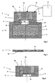
- L'invention sera mieux comprise à la lecture de la description qui va suivre de différents modes de réalisation, description faite en référence aux dessins annexés et dans lesquels :
- la
figure 1 est une vue en coupe d'un composant d'amorçage selon un premier mode de réalisation, - la
figure 2 est une vue partielle d'une variante de réalisation du fusible utilisé dans le composant d'amorçage, - la
figure 3 est une vue en coupe d'un composant d'amorçage selon un deuxième mode de réalisation, - la
figure 4 est une vue en coupe d'un composant d'amorçage selon un troisième mode de réalisation, - la
figure 5 est une vue en coupe d'un composant d'amorçage selon un quatrième mode de réalisation, - la
figure 6 est une vue en coupe d'un composant d'amorçage selon un cinquième mode de réalisation. - En se reportant à la
figure 1 , un composant d'amorçage de sécurité 1 selon l'invention est fixé par des moyens appropriés (non représentés) à une charge explosive 2 comprenant un explosif 3 disposé dans une enveloppe 4. - La charge explosive sera par exemple un relais de détonation en hexogène à l'état pulvérulent ou bien comprimé. On pourrait à titre de variante initier directement sans relais le chargement explosif d'une munition.
- Le composant 1 comprend au moins deux électrodes 5a et 5b qui sont reliées par un fusible 6.
- Une première électrode axiale 5a est constituée d'une tige cylindrique métallique. Elle est entourée par un tube 7 d'un matériau isolant lui-même entouré par une électrode périphérique cylindrique 5b.
- L'électrode périphérique 5b présente donc un logement interne 8 qui reçoit le tube isolant 7 et l'électrode axiale 5a. Ce logement 8 est partiellement refermé par un rebord annulaire 9 de l'électrode périphérique qui présente un trou axial 10.
- Le trou axial 10 est disposé en regard d'un autre trou 11 aménagé dans l'enveloppe 4 de la charge explosive 2.
- Selon l'invention le fusible 6 est réalisé sous la forme d'une feuille d'un matériau plasmagène c'est à dire un matériau fournissant des gaz à haute température (supérieure à 15000 K) et ayant une densité électronique forte (supérieure à 1018 électrons / cm3) lorsqu'il est parcouru par un courant électrique d'au moins 5000 ampères.
- Cette feuille fusible est appliquée en appui sur une face d'extrémité 22 de l'électrode axiale 5a et elle est également en contact avec la partie annulaire 9 de l'électrode périphérique 5b.
- Le matériau plasmagène comprendra au moins un matériau conducteur associé à au moins un matériau énergétique ou susceptible de réagir avec le matériau conducteur.
- On entend par matériau énergétique un matériau susceptible de fournir de l'énergie chimique sous la forme d'une flamme lorsqu'il se trouve initié par l'effet joule engendré par le passage du courant dans le matériau conducteur auquel il est intimement associé.
- On entend par matériau réactif ou susceptible de réagir avec le matériau conducteur un matériau, inerte isolément, mais susceptible de réagir chimiquement avec le matériau conducteur lors de l'échauffement de celui ci par effet Joule. De l'énergie chimique se trouve alors fournie par cette réaction sous la forme d'une flamme.
- Le matériau conducteur pourra être constitué par du carbone ou bien par un métal tel du cuivre, de l'aluminium, de l'argent ou du magnésium.
- Le matériau énergétique ou susceptible de réagir avec le matériau conducteur pourra être choisi parmi les composés ou compositions suivantes :
- Oxyde de cuivre; polytétrafluoréthylène; copolymère de chlorofluoroéthylène; polytétrafluoréthylène/copolymère de chlorofluoroéthylène; Magnésium / polytétrafluoréthylène / copolymère de chlorofluoro-éthylène; Bore/Nitrate de potassium; pellicule ou film de nitrocellulose plastifiée; nitrate de polyvinyle; polyoxyméthylène; Polychlorure de trifluoroéthylène; polychlorure de vinyle; Polychlorure de trifluoroéthylène; polysulfone; polyfluorure de vinylidène.
- Dans cette liste les matériaux énergétiques sont les compositions : Magnésium / polytétrafluoréthylène / copolymère de chlorofluoro-éthylène; Bore/Nitrate de potassium; pellicule ou film de nitrocellulose plastifiée; nitrate de polyvinyle.
- Les matériaux réactifs avec un matériau conducteur sont : Oxyde de cuivre; polytétrafluoréthylène; copolymère de chlorofluoroéthylène; polytétrafluoréthylène/copolymère de chlorofluoroéthylène; Polyoxyméthylène; Polychlorure de trifluoroéthylène; Polychlorure de vinyle; Polysulfone; Polyfluorure de vinylidène.
- Suivant le mode particulier de réalisation de la
figure 1 , la feuille fusible 6 est formée par un mélange homogène associant 85% à 95% en masse de particules de matériau conducteur et 5% à 15% en masse d'un matériau énergétique ou bien susceptible de réagir avec le matériau conducteur. - On pourra par exemple réaliser une feuille fusible avec les compositions suivantes :
- 85% à 95% en masse de poudre d'aluminium et de préférence 90%,
5% à 15% en masse d'un mélange associant polytétrafluoréthylène et copolymère de chlorofluoroéthylène, et de préférence 10%. - 85% à 95% en masse de poudre de magnésium et de préférence 90%,
5% à 15% en masse d'un mélange associant polytétrafluoréthylène et copolymère de chlorofluoroéthylène, et de préférence 10%. - On pourra concrètement réaliser la feuille en mélangeant le métal (aluminium ou magnésium) à une solution de polytétrafluoréthylène et de copolymère de chlorofluoroéthylène dans un solvant approprié, par exemple une cétone : cyclohexyl cétone (cyclohexane) ou acétone. Le mélange ainsi réalisé sera appliqué comme une peinture sur la face d'extrémité de l'électrode axiale 5a et du tube isolant 7. Puis le solvant sera évaporé avant mise en place de l'électrode 5a et du tube isolant 7 dans l'électrode périphérique 5b.
- Le composant 1 et relié par des conducteurs 21 et 13 à un générateur électrique 14.
- Ce générateur est conçu pour pouvoir délivrer une énergie de 10 kJ à 1 mégaJoule sous forme d'impulsions de tension de 1000 volts à 20 kilo Volts. Un tel générateur est classique et comprend par exemple des capacités, une inductance, des interrupteurs (comme les thyristors ou les éclateurs) et une alimentation stabilisée.
- Une faible fraction de l'énergie fournie par le générateur est utilisée pour initier la feuille fusible 6 par effet joule. Le matériau énergétique est alors initié ou bien la réaction entre le matériau conducteur et le matériau réactif est initiée. Une flamme de combustion remplit la chambre 12 qui est constituée par le trou 10 et qui est délimitée par l'électrode périphérique 5b.
- Cette flamme est formée naturellement d'atomes et molécules ionisés. Elle assure une conduction électrique de résistance réduite entre les électrodes 5a et 5b qui permet le maintien d'un arc électrique entre les électrodes.
- La chambre 12 assure un confinement de l'arc qui permet le développement du plasma engendré par la feuille fusible 6.
- Il en résulte une onde de choc très intense (combinée généralement à une projection d'une partie de la feuille fusible), qui impacte le chargement explosif 3 au travers du trou 11 et assure l'initiation de celui ci.
- La pression engendrée sera d'autant plus importante que le volume de la chambre 12 sera réduit.
- A titre d'exemple on a réalisé un composant d'allumage associant une chambre 12 ayant un volume d'environ 17 mm3 et un fusible énergétique de 4 mm de diamètre efficace (diamètre de la chambre 12), 90 micromètres d'épaisseur et ayant comme composition l'une ou l'autre des compositions décrites précédemment (exemples 1 ou 2).
- Un tel composant, alimenté sous une impulsion de tension de 1000 Volts avec une intensité maximale de 10000 Ampères, a assuré la mise en détonation d'un relais explosif de 11,5mm de diamètre et 11,5mm de haut réalisé en hexogène/cire/graphite (proportions en masses relatives : 98/2/1). La pression obtenue en sortie du composant est de l'ordre de 1 Giga pascal (1 GPa).
- On voit que le composant selon l'invention est d'une fabrication plus simple que celle des composant de sécurité ou "slappers" connus puisqu'il ne nécessite pas la réalisation d'un pont résistif et d'un canon de projection pour une pastille.
- Le diamètre de la chambre 12 (entre 1 et 4 mm) est supérieur à celui des canons utilisés dans les "slappers" connus (dont le diamètre est généralement inférieur au mm).
- La tension d'alimentation est également plus faible (de l'ordre de 1000 volts contre près de 3000 Volts pour les "slappers" connus). On réduit ainsi fortement les problèmes d'isolation et on facilite donc l'intégration du composant dans les munitions ou les systèmes de sécurité automobiles.
- La puissance électrique consommée est du même ordre que dans celle des "slappers" connus (10 Méga Watts), l'intensité maximale étant également plus forte (environ 10 kilo Ampères).
- Le composant selon l'invention est un composant de sécurité puisque le niveau d'énergie nécessaire pour son initiation satisfait aux exigences données par les normes: pas de réaction pyrotechnique pour une impulsion de moins de 500 volts. Il peut donc être utilisé dans un dispositif d'amorçage dépourvu de moyen de désalignement de la chaîne pyrotechnique.
- Il est possible en fonction des besoins de jouer sur les différentes dimensions du composant pour définir un composant fonctionnant avec une tension plus faible que 1000 volts. On pourra ainsi réduire l'épaisseur de la feuille fusible et/ou le volume de la chambre 12 pour modifier la pression de plasma engendrée donc la puissance du composant.
- Il est possible à titre de variante de remplacer la feuille fusible représentée à la
figure 1 (en matériau formé d'un mélange homogène) par une feuille 6 comme celle représentée à lafigure 2 qui comprend une couche 16 de matériau conducteur sur laquelle est déposée au moins une couche 15 d'un matériau énergétique ou bien susceptible de réagir avec le matériau conducteur. - Pour réaliser un tel fusible, on pourra par exemple projeter sur une feuille métallique un mélange de colle et du matériau énergétique ou pouvant réagir avec le matériau conducteur.
- Concrètement on pourra réaliser un fusible comportant une feuille d'aluminium ou de magnésium sur laquelle est déposée une couche de polytétrafluoréthylène ou de chlorure de polyvinyle.
- L'épaisseur de la (ou des) couches métalliques sera de l'ordre de 150 micromètres. Celle du matériau énergétique sera de l'ordre de 100 micromètres.
- On pourra également associer une couche d'aluminium ou de magnésium avec une couche de nitrocellulose ou de nitrate de polyvinyle.
- On pourra réaliser un dépôt d'oxyde de cuivre ou de copolymère de chlorofluoroéthylène sur une feuille d'aluminium ou de magnésium.
- On pourra également réaliser un dépôt de polyoxyméthylène sur une couche d'aluminium.
- Dans tous les cas les dimensions des différentes couches seront telles qu'on associera de 85 à 95% en masse du matériau de la couche conductrice à 5 à 15% en masse du ou des matériaux de la ou des couches réactives.
- Suivant un mode de réalisation préféré, on réalisera une feuille fusible en déposant au moins une couche de copolymère de chlorofluoroéthylène (connu sous la marque déposée Viton) sur une couche d'aluminium. Les proportions en masse relatives seront de 90% pour l'aluminium et de 10% pour le copolymère de chlorofluoroéthylène.
- La
figure 3 montre un composant selon l'invention équipé d'un fusible selon lafigure 2 . Pour la simplification de la figure le composant 1 a été représenté seul sans le chargement explosif qu'il doit initier - La feuille fusible 6 est disposée de telle sorte que la couche métallique 16 se trouve en contact avec la face avant de l'électrode axiale 5a.
- La feuille fusible 6 aura un diamètre choisi tel que la couche métallique 16 se trouve également en contact avec la surface cylindrique interne 8 de l'électrode périphérique 5b.
- Le passage du courant pourra ainsi se faire au travers de la couche conductrice 16 qui assurera par effet joule l'initiation de la réaction avec la couche énergétique 15 donc la génération du plasma.
- On a réalisé ainsi un composant comportant un fusible sous la forme d'une feuille comprenant une couche de 80 micromètres d'épaisseur d'aluminium portant une couche de 11 micromètres de copolymère de chlorofluoroéthylène (connu sous la marque déposée Viton). La feuille fusible ainsi réalisée a un diamètre de 8 mm et le composant présente une chambre 12 de volume 17 mm3 environ.
- Ce composant a pu initier un comprimé explosif tel que décrit précédemment en réponse à une impulsion de tension de 1000 volts pour une intensité maximale de 10 kilo Ampères.
- On a également réalisé un composant de géométrie identique à celle du précédent mais dont la feuille fusible comporte une couche de 80 micromètres d'épaisseur de Magnésium portant une couche de 11 micromètres de copolymère de chlorofluoroéthylène
- On a enfin réalisé un composant de géométrie identique à celle des précédents mais dont la feuille fusible comporte une couche de 80 micromètres d'épaisseur de Magnésium portant une couche de 11 micromètres de polytétrafluoréthylène (connu sous la marque déposée Téflon).
- Ces composants ont également initié avec succès le comprimé explosif décrit précédemment.
- Afin d'initier des explosifs moins sensibles ou de paramétrer de façon plus précise les performances d'initiation du composant selon l'invention, il est possible de définir un composant comportant également (comme dans les composants "slappers" classiques) une pastille projetable.
- La
figure 4 montre un tel composant 1. - Comme dans le mode de réalisation de la
figure 3 , le composant 1 comprend deux électrodes 5a et 5b qui sont reliées par un fusible 6. - L'électrode périphérique 5b présente un logement interne 8 qui reçoit un tube isolant 7 et l'électrode axiale 5a. Le logement 8 est partiellement refermé par un rebord annulaire 9 de l'électrode périphérique.
- Le fusible 6 comprend une couche conductrice 16 en contact électrique avec une face avant de l'électrode centrale 5a et avec la surface cylindrique interne du logement 8. Ce composant diffère de celui de la
figure 3 en ce qu'une pastille 17 est disposée entre le rebord annulaire 9 et le fusible. Cette pastille sépare donc la chambre 12 et la feuille fusible 6. - La pastille sera réalisée en un matériau isolant électrique ou recouvert d'une couche isolante électrique. Une telle disposition permet d'éviter les amorçages d'arcs électriques directement entre l'électrode axiale 5a et la pastille. On pourra par exemple réaliser la pastille en une matière plastique tel un polyimide (matériau connu sous la marque déposée Kapton). On pourra également réaliser la pastille en mica ou encore en métal (aluminium, titane ou acier). Dans le cas d'une pastille en métal on recouvrira celle ci sur ses deux faces avec un matériau isolant, par exemple du polytétrafluoréthylène, ou une couche de ruban adhésif isolant assurant un niveau d'isolation électrique approprié (par exemple au moins 1000 volts). De tels rubans isolants mettent généralement en oeuvre une couche isolante de caoutchouc ou de chlorure de polyvinyle (PVC).
- On a ainsi réalisé des pastilles projetables en acier de 20 à 120 micromètres d'épaisseur.
- Lors du passage du courant dans le fusible la pression engendré par la réaction entre le matériau conducteur et le matériau énergétique provoque la découpe de la pastille et sa projection au travers de la chambre 12 qui joue ainsi le rôle du "canon" des composants "slappers" classiques.
- Il n'est donc pas nécessaire comme dans les slappers connus de prévoir un composant canon spécifique (tube en céramique de l'ordre du mm de diamètre).
- Le diamètre de la chambre pourra varier entre 1 et 4 mm.
- L'Homme du Métier choisira aisément les dimensions appropriées pour assurer l'effet recherché. On pourra notamment jouer sur l'épaisseur, donc la masse de la pastille, pour modifier l'énergie reçue par l'explosif à initier.
- A titre d'exemple on a réalisé des composants incorporant un fusible associant une couche d'aluminium et une couche de copolymère de chlorofluoroéthylène (connu sous la marque déposée Viton) avec les proportions en masses respectives de 90% et 10% (épaisseur totale du fusible 100 micromètres).
- On a disposé dans chaque composant une pastille à projeter associée à une chambre de diamètre 2 ou 4mm, pastille ayant une épaisseur de 40 micromètres pour de l'acier ou 120 micromètres pour du Kapton. Tous les composants ont conduit à l'initiation d'un comprimé d'hexogène de 11,5mm x 11,5mm comprimé sous 160 MPa.
- Les mêmes essais ont été conduit avec succés en utilisant un fusible associant une couche de magnésium et une couche de polytétrafluoréthylène (connu sous la marque déposée téflon) avec les proportions en masses respectives de 90% et 10%.
- La
figure 5 montre un composant suivant un quatrième mode de réalisation. Ce composant diffère de celui selon lafigure 3 en ce que la chambre 12 constitue un logement à l'intérieur duquel est disposé un pion 18 projetable par la feuille fusible. Le pion a sensiblement le même volume que le logement et il remplit celui ci entièrement. Il est rendu solidaire du composant par exemple par collage. - Afin d'éviter les court circuits entre l'électrode axiale 5a et le pion, celui ci sera réalisé en un matériau isolant électrique ou bien en un matériau recouvert d'un isolant.
- La pion pourra par exemple être réalisé en une matière plastique telle que du polytetrafluoréthylène.
- L'avantage d'un tel mode de réalisation est qu'il engendre une onde de choc qui se propage jusqu'à l'explosif au travers du milieu solide du pion. Il en résulte un meilleur rendement énergétique et une efficacité supérieure pour initier un explosif peu sensible. Le diamètre du pion devra être dans tous les cas supérieur au diamètre critique de l'explosif à initier.
- La
figure 6 montre un cinquième mode de réalisation de l'invention dans lequel l'électrode axiale 5a, le tube d'un matériau isolant 7 et l'électrode périphérique 5b constituent un câble coaxial présentant une face d'extrémité plane 19 et une gaine isolante externe 20. - On pourra par exemple prendre un câble coaxial du commerce de diamètre externe 1,5 mm, comprenant une âme axiale 5a de 0,2 mm de diamètre et un conducteur périphérique 5b formant une couronne de 0,2 mm d'épaisseur. La couronne isolante 7 aura environ 100 micromètres d'épaisseur.
- La face 19 est tronçonnée et rectifiée.
- La feuille fusible 6 est alors réalisée sous la forme d'une couche de matériau plasmagène appliqué sur la face d'extrémité 19.
- On pourra avantageusement choisir comme matériau plasmagène une peinture associant un matériau conducteur, tel le carbone ou un métal (aluminium, nickel, cuivre), avec un liant polymérisable tel que le polyuréthane.
- On pourra par exemple associer 70% à 90% en masse de poudre d'aluminium avec 30% à 10% en masse de polyuréthane. On réalisera une feuille fusible de quelques micromètres d'épaisseur tout simplement par enduction de l'extrémité du câble coaxial avec le matériau ainsi réalisé puis séchage.
- On pourra également associer 70% à 90% en masse de poudre d'aluminium, de Nickel ou d'argent avec 30% à 10% en masse d'une résine acrylique.
- Ce mode de réalisation est de mise en oeuvre extrêmement simple. Il permet également de diminuer fortement le niveau d'énergie nécessaire pour l'initiation. Ce niveau peut ainsi êrte de l'ordre de quelques dizaines de Joules.
- On rendra le câble initiateur solidaire de la charge à initier par un moyen de liaison approprié par exemple un serre câble fileté qui se vissera sur l'enveloppe de la charge en regard du chargement explosif.
Claims (26)
- Composant (1) d'amorçage de sécurité comprenant au moins deux électrodes (5a,5b) reliées par un fusible (6) réalisé sous la forme d'une feuille d'un matériau plasmagène caractérisé en ce que le matériau du fusible (6) comprend au moins un matériau conducteur associé à au moins un matériau énergétique ou susceptible de réagir avec le matériau conducteur.
- Composant d'amorçage de sécurité selon la revendication 1, caractérisé en ce que le matériau conducteur est constitué par du carbone ou bien un métal.
- Composant d'amorçage de sécurité selon la revendication 2, caractérisé en ce que le matériau énergétique ou susceptible de réagir avec le matériau conducteur est choisi parmi les composés ou compositions suivantes :Oxyde de cuivre; polytétrafluoroéthylène; copolymère de chlorofluoroéthylène; polytétrafluoroéthylène/copolymère de chlorofluoroéthylène; Magnésium / polytétrafluoroéthylène /copolymère de chlorofluoroéthylène; Bore/Nitrate de potassium; pellicule ou film de nitrocellulose plastifiée; nitrate de polyvinyle; Polyoxyméthylène; Polychlorure de trifluoroéthylène; polychlorure de vinyle; Polychlorure de trifluoroéthylène; polysulfone; polyfluorure de vinylidène.
- Composant d'amorçage de sécurité suivant une des revendications 2 ou 3, caractérisé en ce que la feuille fusible (6) est formée par un mélange homogène associant 85% à 95% en masse de particules de matériau conducteur et de 5% à 15% en masse d'un matériau énergétique ou bien susceptible de réagir avec le matériau conducteur.
- Composant d'amorçage de sécurité suivant la revendication 4, caractérisé en ce que la feuille fusible (6) a pour composition :- 85% à 95% en masse de poudre d'aluminium ou de magnésium,- 5% à 15% en masse d'une composition associant polytétrafluoroéthylène et copolymère de chlorofluoroéthylène.
- Composant d'amorçage de sécurité suivant la revendication 5, caractérisé en ce que la feuille fusible (6) a pour composition :- 90% en masse de poudre d'aluminium,- 10% en masse d'une composition associant polytétrafluoroéthylène et copolymère de chlorofluoroéthylène.
- Composant d'amorçage de sécurité suivant la revendication 5, caractérisé en ce que la feuille fusible (6) a pour composition :- 90% en masse de poudre de magnésium,- 10% en masse d'une composition associant polytétrafluoroéthylène et copolymère de chlorofluoroéthylène.
- Composant d'amorçage de sécurité suivant une des revendications 1 à 3, caractérisé en ce que la feuille fusible (6) comporte au moins une couche (15) de matériau énergétique ou bien susceptible de réagir avec le matériau conducteur déposé sur au moins une partie d'une couche (16) de matériau conducteur.
- Composant d'amorçage de sécurité suivant la revendication 8, caractérisé en ce que le fusible (6) comprend au moins une couche conductrice (16) d'aluminium ou de magnésium sur laquelle est déposée au moins une couche réactive (15) de polytétrafluoroéthylène, ou de nitrocellulose ou de nitrate de polyvinyle, ou d'oxyde de cuivre ou de copolymère de chlorofluoroéthylène, ou de polyoxyméthylène, ou de Polychlorure de trifluoroéthylène, ou de polysulfone, ou de polyfluorure de vinylidène.
- Composant d'amorçage de sécurité suivant la revendication 9, caractérisé en ce que les dimensions des différentes couches sont telles qu'on associe de 85 à 95% en masse du matériau de la couche conductrice à 5 à 15% en masse du ou des matériaux de la ou des couches réactives.
- Composant d'amorçage de sécurité suivant la revendication 10, caractérisé en ce que le fusible (6) comprend au moins une couche (16) d'aluminium et au moins une couche (15) de copolymère de chlorofluoroéthylène.
- Composant d'amorçage de sécurité suivant la revendication 10, caractérisé en ce que le fusible (6) comprend au moins une couche de magnésium et au moins une couche de copolymère de chlorofluoroéthylène.
- Composant d'amorçage de sécurité suivant la revendication 10, caractérisé en ce que le fusible (6) comprend au moins une couche de magnésium et au moins une couche de polytétrafluoroéthylène.
- Composant d'amorçage de sécurité suivant une des revendications 1 à 13, caractérisé en ce qu'il comprend une électrode axiale (5a) entourée par un tube (7) d'un matériau isolant lui-même entouré par une électrode périphérique (5b), la feuille fusible (6) étant appliquée en appui sur une face d'extrémité (22) de l'électrode axiale (5a) et étant également en contact avec une partie annulaire (9) de l'électrode périphérique (5b).
- Composant d'amorçage de sécurité selon la revendication 14, caractérisé en ce qu'il comprend une chambre (12) pour le développement du plasma, chambre séparée d'au moins une électrode par la feuille fusible (6).
- Composant d'amorçage de sécurité suivant la revendication 15, caractérisé en ce que la chambre (12) est délimitée par l'électrode périphérique (5b).
- Composant d'amorçage de sécurité suivant une des revendications 15 ou 16, caractérisée en ce qu'il comprend également une pastille (17) projetable à travers la chambre (12), pastille (17) disposée entre la chambre (12) et la feuille fusible (6).
- Composant d'amorçage de sécurité suivant la revendication 17, caractérisé en ce que la pastille (17) est réalisée en une matière isolante électrique ou recouverte d'une couche isolante électrique.
- Composant d'amorçage de sécurité suivant la revendication 18, caractérisée en ce que la pastille (17) a un diamètre compris entre 1 mm et 4 mm et une épaisseur comprise entre 20 et 200 micromètres.
- Composant d'amorçage de sécurité selon la revendication 14, caractérisé en ce qu'il comprend un logement (12) séparé d'au moins une électrode par la feuille fusible (6), logement à l'intérieur duquel est disposé un pion (18) projetable par la feuille fusible (6).
- Composant d'amorçage de sécurité selon la revendication 20, caractérisé en ce que le pion (18) a sensiblement le même volume que le logement (12).
- Composant d'amorçage de sécurité suivant la revendication 21, caractérisé en ce que le logement (12) est délimité par l'électrode périphérique (5b) et en ce que le pion (18) est réalisé en un matériau isolant électrique ou recouvert d'une couche isolante électrique.
- Composant d'amorçage de sécurité selon la revendication 14, caractérisé en ce que l'électrode axiale (5a), le tube (7) d'un matériau isolant et l'électrode périphérique (5b) constituent un câble coaxial présentant une face d'extrémité plane (19), et en ce que la feuille fusible (6) est réalisée sous la forme d'une couche de matériau plasmagène appliquée sur la face d'extrémité (19).
- Composant d'amorçage de sécurité selon la revendication 23, caractérisé en ce que la couche de matériau plasmagène est constituée par une peinture associant un matériau conducteur avec un liant polymérisable.
- Composant d'amorçage de sécurité selon la revendication 24, caractérisé en ce que la couche de matériau plasmagène comprend 70% à 90% en masse de poudre d'aluminium, de Nickel ou d'argent avec 30% à 10% en masse d'une résine acrylique.
- Composant d'amorçage de sécurité selon la revendication 24, caractérisé en ce que la couche de matériau plasmagène comprend 70% à 90% en masse de poudre d'aluminium, avec 30% à 10% en masse de polyuréthane.
Applications Claiming Priority (2)
| Application Number | Priority Date | Filing Date | Title |
|---|---|---|---|
| FR0206590 | 2002-05-29 | ||
| FR0206590A FR2840400B1 (fr) | 2002-05-29 | 2002-05-29 | Composant d'amorcage de securite |
Publications (2)
| Publication Number | Publication Date |
|---|---|
| EP1367356A1 EP1367356A1 (fr) | 2003-12-03 |
| EP1367356B1 true EP1367356B1 (fr) | 2008-09-03 |
Family
ID=29415145
Family Applications (1)
| Application Number | Title | Priority Date | Filing Date |
|---|---|---|---|
| EP03291268A Expired - Lifetime EP1367356B1 (fr) | 2002-05-29 | 2003-05-27 | Amorce de sécurité |
Country Status (4)
| Country | Link |
|---|---|
| EP (1) | EP1367356B1 (fr) |
| AT (1) | ATE407339T1 (fr) |
| DE (1) | DE60323294D1 (fr) |
| FR (1) | FR2840400B1 (fr) |
Family Cites Families (6)
| Publication number | Priority date | Publication date | Assignee | Title |
|---|---|---|---|---|
| GB2100395B (en) * | 1981-06-15 | 1984-08-01 | Secr Defence | Pyrotechnic devices |
| FR2669725B1 (fr) * | 1990-11-27 | 1994-10-07 | Thomson Brandt Armements | Detonateur pyrotechnique a connexions coaxiales. |
| US5370053A (en) * | 1993-01-15 | 1994-12-06 | Magnavox Electronic Systems Company | Slapper detonator |
| US6327978B1 (en) * | 1995-12-08 | 2001-12-11 | Kaman Aerospace Corporation | Exploding thin film bridge fracturing fragment detonator |
| US6234081B1 (en) * | 1999-03-19 | 2001-05-22 | Eg&G, Inc. | Shaped bridge slapper |
| US6298784B1 (en) * | 1999-10-27 | 2001-10-09 | Talley Defense Systems, Inc. | Heat transfer delay |
-
2002
- 2002-05-29 FR FR0206590A patent/FR2840400B1/fr not_active Expired - Fee Related
-
2003
- 2003-05-27 EP EP03291268A patent/EP1367356B1/fr not_active Expired - Lifetime
- 2003-05-27 DE DE60323294T patent/DE60323294D1/de not_active Expired - Lifetime
- 2003-05-27 AT AT03291268T patent/ATE407339T1/de not_active IP Right Cessation
Also Published As
| Publication number | Publication date |
|---|---|
| EP1367356A1 (fr) | 2003-12-03 |
| FR2840400B1 (fr) | 2004-07-16 |
| DE60323294D1 (de) | 2008-10-16 |
| ATE407339T1 (de) | 2008-09-15 |
| FR2840400A1 (fr) | 2003-12-05 |
Similar Documents
| Publication | Publication Date | Title |
|---|---|---|
| EP1185833B1 (fr) | Torche a plasma incorporant un fusible d'amorcage reactif et tube allumeur integrant une telle torche | |
| EP0905470B1 (fr) | Composant d'allumage pour composition pyrotechnique ou charge propulsive | |
| EP1030159B1 (fr) | Allumeur électropyrotechnique à sécurité d'allumage renforcé | |
| US7574960B1 (en) | Ignition element | |
| FR2669725A1 (fr) | Detonateur pyrotechnique a connexions coaxiales. | |
| EP1306643B1 (fr) | Détonateur optique basse énergie | |
| EP0468838B1 (fr) | Système d'allumage pour une composition pyrotechnique | |
| EP1273875B1 (fr) | Dispositif d'allumage pour un chargement propulsif | |
| EP0717256B1 (fr) | Système de mise à feu par arc électrique d'une munition sans douille | |
| EP1367355B1 (fr) | Amorce de sécurité à torche à plasma | |
| EP0076210B1 (fr) | Initiateur pyrotechnique électrique à effet Joule | |
| EP1367356A1 (fr) | Amorce de sécurité | |
| EP1067354B1 (fr) | Dispositif d'initiation d'une composition énergétique | |
| FR2617277A1 (fr) | Inflammateur pour generateur pyrotechnique | |
| EP0076746B1 (fr) | Composition pyrotechnique et dispositifs inflammateurs pyrotechniques | |
| FR2669724A1 (fr) | Detonateur laser a effet de projection de plaque. | |
| EP0526315A1 (fr) | Contacteur électrique à commande pyrotechnique | |
| EP2508838B1 (fr) | Inflammateur, composant pyrotechnique et procédé de fabrication d'un tel composant pyrotechnique | |
| EP2827091B1 (fr) | Initiateur électrique ayant deux modes de fonctionnement | |
| EP0592292B1 (fr) | Amorce électrique à composition conductrice | |
| FR2859065A1 (fr) | Generateur de plasma. | |
| EP1403611A1 (fr) | Inflammateur à double effet et procédé d'allumage mettant en oeuvre un tel inflammateur | |
| FR2874255A1 (fr) | Allumeur de charges propulsives | |
| EP0402268A1 (fr) | Inflammateur pyrotechnique pour charges militaires ou propulseur ou générateur de gaz |
Legal Events
| Date | Code | Title | Description |
|---|---|---|---|
| PUAI | Public reference made under article 153(3) epc to a published international application that has entered the european phase |
Free format text: ORIGINAL CODE: 0009012 |
|
| AK | Designated contracting states |
Kind code of ref document: A1 Designated state(s): AT BE BG CH CY CZ DE DK EE ES FI FR GB GR HU IE IT LI LU MC NL PT RO SE SI SK TR |
|
| AX | Request for extension of the european patent |
Extension state: AL LT LV MK |
|
| 17P | Request for examination filed |
Effective date: 20031222 |
|
| AKX | Designation fees paid |
Designated state(s): AT BE BG CH CY CZ DE DK EE ES FI FR GB GR HU IE IT LI LU MC NL PT RO SE SI SK TR |
|
| 17Q | First examination report despatched |
Effective date: 20060626 |
|
| RAP1 | Party data changed (applicant data changed or rights of an application transferred) |
Owner name: NEXTER MUNITIONS |
|
| GRAP | Despatch of communication of intention to grant a patent |
Free format text: ORIGINAL CODE: EPIDOSNIGR1 |
|
| GRAS | Grant fee paid |
Free format text: ORIGINAL CODE: EPIDOSNIGR3 |
|
| GRAA | (expected) grant |
Free format text: ORIGINAL CODE: 0009210 |
|
| AK | Designated contracting states |
Kind code of ref document: B1 Designated state(s): AT BE BG CH CY CZ DE DK EE ES FI FR GB GR HU IE IT LI LU MC NL PT RO SE SI SK TR |
|
| REG | Reference to a national code |
Ref country code: GB Ref legal event code: FG4D Free format text: NOT ENGLISH |
|
| REG | Reference to a national code |
Ref country code: CH Ref legal event code: EP |
|
| REG | Reference to a national code |
Ref country code: CH Ref legal event code: NV Representative=s name: ING. MARCO ZARDI C/O M. ZARDI & CO. S.A. |
|
| REG | Reference to a national code |
Ref country code: IE Ref legal event code: FG4D Free format text: LANGUAGE OF EP DOCUMENT: FRENCH |
|
| REF | Corresponds to: |
Ref document number: 60323294 Country of ref document: DE Date of ref document: 20081016 Kind code of ref document: P |
|
| REG | Reference to a national code |
Ref country code: SE Ref legal event code: TRGR |
|
| PG25 | Lapsed in a contracting state [announced via postgrant information from national office to epo] |
Ref country code: NL Free format text: LAPSE BECAUSE OF FAILURE TO SUBMIT A TRANSLATION OF THE DESCRIPTION OR TO PAY THE FEE WITHIN THE PRESCRIBED TIME-LIMIT Effective date: 20080903 Ref country code: ES Free format text: LAPSE BECAUSE OF FAILURE TO SUBMIT A TRANSLATION OF THE DESCRIPTION OR TO PAY THE FEE WITHIN THE PRESCRIBED TIME-LIMIT Effective date: 20081214 |
|
| PG25 | Lapsed in a contracting state [announced via postgrant information from national office to epo] |
Ref country code: AT Free format text: LAPSE BECAUSE OF FAILURE TO SUBMIT A TRANSLATION OF THE DESCRIPTION OR TO PAY THE FEE WITHIN THE PRESCRIBED TIME-LIMIT Effective date: 20080903 Ref country code: SI Free format text: LAPSE BECAUSE OF FAILURE TO SUBMIT A TRANSLATION OF THE DESCRIPTION OR TO PAY THE FEE WITHIN THE PRESCRIBED TIME-LIMIT Effective date: 20080903 Ref country code: FI Free format text: LAPSE BECAUSE OF FAILURE TO SUBMIT A TRANSLATION OF THE DESCRIPTION OR TO PAY THE FEE WITHIN THE PRESCRIBED TIME-LIMIT Effective date: 20080903 |
|
| NLV1 | Nl: lapsed or annulled due to failure to fulfill the requirements of art. 29p and 29m of the patents act | ||
| REG | Reference to a national code |
Ref country code: IE Ref legal event code: FD4D |
|
| PG25 | Lapsed in a contracting state [announced via postgrant information from national office to epo] |
Ref country code: BG Free format text: LAPSE BECAUSE OF FAILURE TO SUBMIT A TRANSLATION OF THE DESCRIPTION OR TO PAY THE FEE WITHIN THE PRESCRIBED TIME-LIMIT Effective date: 20081203 Ref country code: IE Free format text: LAPSE BECAUSE OF FAILURE TO SUBMIT A TRANSLATION OF THE DESCRIPTION OR TO PAY THE FEE WITHIN THE PRESCRIBED TIME-LIMIT Effective date: 20080903 |
|
| PG25 | Lapsed in a contracting state [announced via postgrant information from national office to epo] |
Ref country code: PT Free format text: LAPSE BECAUSE OF FAILURE TO SUBMIT A TRANSLATION OF THE DESCRIPTION OR TO PAY THE FEE WITHIN THE PRESCRIBED TIME-LIMIT Effective date: 20090203 Ref country code: RO Free format text: LAPSE BECAUSE OF FAILURE TO SUBMIT A TRANSLATION OF THE DESCRIPTION OR TO PAY THE FEE WITHIN THE PRESCRIBED TIME-LIMIT Effective date: 20080903 Ref country code: CZ Free format text: LAPSE BECAUSE OF FAILURE TO SUBMIT A TRANSLATION OF THE DESCRIPTION OR TO PAY THE FEE WITHIN THE PRESCRIBED TIME-LIMIT Effective date: 20080903 Ref country code: SK Free format text: LAPSE BECAUSE OF FAILURE TO SUBMIT A TRANSLATION OF THE DESCRIPTION OR TO PAY THE FEE WITHIN THE PRESCRIBED TIME-LIMIT Effective date: 20080903 |
|
| PLBE | No opposition filed within time limit |
Free format text: ORIGINAL CODE: 0009261 |
|
| STAA | Information on the status of an ep patent application or granted ep patent |
Free format text: STATUS: NO OPPOSITION FILED WITHIN TIME LIMIT |
|
| PG25 | Lapsed in a contracting state [announced via postgrant information from national office to epo] |
Ref country code: EE Free format text: LAPSE BECAUSE OF FAILURE TO SUBMIT A TRANSLATION OF THE DESCRIPTION OR TO PAY THE FEE WITHIN THE PRESCRIBED TIME-LIMIT Effective date: 20080903 Ref country code: DK Free format text: LAPSE BECAUSE OF FAILURE TO SUBMIT A TRANSLATION OF THE DESCRIPTION OR TO PAY THE FEE WITHIN THE PRESCRIBED TIME-LIMIT Effective date: 20080903 |
|
| 26N | No opposition filed |
Effective date: 20090604 |
|
| BERE | Be: lapsed |
Owner name: NEXTER MUNITIONS Effective date: 20090531 |
|
| PG25 | Lapsed in a contracting state [announced via postgrant information from national office to epo] |
Ref country code: MC Free format text: LAPSE BECAUSE OF NON-PAYMENT OF DUE FEES Effective date: 20090531 |
|
| PG25 | Lapsed in a contracting state [announced via postgrant information from national office to epo] |
Ref country code: BE Free format text: LAPSE BECAUSE OF NON-PAYMENT OF DUE FEES Effective date: 20090531 |
|
| PG25 | Lapsed in a contracting state [announced via postgrant information from national office to epo] |
Ref country code: GR Free format text: LAPSE BECAUSE OF FAILURE TO SUBMIT A TRANSLATION OF THE DESCRIPTION OR TO PAY THE FEE WITHIN THE PRESCRIBED TIME-LIMIT Effective date: 20081204 |
|
| PG25 | Lapsed in a contracting state [announced via postgrant information from national office to epo] |
Ref country code: LU Free format text: LAPSE BECAUSE OF NON-PAYMENT OF DUE FEES Effective date: 20090527 |
|
| PG25 | Lapsed in a contracting state [announced via postgrant information from national office to epo] |
Ref country code: HU Free format text: LAPSE BECAUSE OF FAILURE TO SUBMIT A TRANSLATION OF THE DESCRIPTION OR TO PAY THE FEE WITHIN THE PRESCRIBED TIME-LIMIT Effective date: 20090304 |
|
| PGFP | Annual fee paid to national office [announced via postgrant information from national office to epo] |
Ref country code: CH Payment date: 20110427 Year of fee payment: 9 Ref country code: SE Payment date: 20110426 Year of fee payment: 9 |
|
| PG25 | Lapsed in a contracting state [announced via postgrant information from national office to epo] |
Ref country code: TR Free format text: LAPSE BECAUSE OF FAILURE TO SUBMIT A TRANSLATION OF THE DESCRIPTION OR TO PAY THE FEE WITHIN THE PRESCRIBED TIME-LIMIT Effective date: 20080903 |
|
| PGFP | Annual fee paid to national office [announced via postgrant information from national office to epo] |
Ref country code: GB Payment date: 20110503 Year of fee payment: 9 |
|
| PG25 | Lapsed in a contracting state [announced via postgrant information from national office to epo] |
Ref country code: CY Free format text: LAPSE BECAUSE OF FAILURE TO SUBMIT A TRANSLATION OF THE DESCRIPTION OR TO PAY THE FEE WITHIN THE PRESCRIBED TIME-LIMIT Effective date: 20080903 |
|
| PGFP | Annual fee paid to national office [announced via postgrant information from national office to epo] |
Ref country code: DE Payment date: 20110505 Year of fee payment: 9 Ref country code: IT Payment date: 20110423 Year of fee payment: 9 |
|
| REG | Reference to a national code |
Ref country code: CH Ref legal event code: PL |
|
| REG | Reference to a national code |
Ref country code: SE Ref legal event code: EUG |
|
| GBPC | Gb: european patent ceased through non-payment of renewal fee |
Effective date: 20120527 |
|
| PG25 | Lapsed in a contracting state [announced via postgrant information from national office to epo] |
Ref country code: CH Free format text: LAPSE BECAUSE OF NON-PAYMENT OF DUE FEES Effective date: 20120531 Ref country code: LI Free format text: LAPSE BECAUSE OF NON-PAYMENT OF DUE FEES Effective date: 20120531 |
|
| PG25 | Lapsed in a contracting state [announced via postgrant information from national office to epo] |
Ref country code: SE Free format text: LAPSE BECAUSE OF NON-PAYMENT OF DUE FEES Effective date: 20120528 Ref country code: IT Free format text: LAPSE BECAUSE OF NON-PAYMENT OF DUE FEES Effective date: 20120527 |
|
| REG | Reference to a national code |
Ref country code: DE Ref legal event code: R119 Ref document number: 60323294 Country of ref document: DE Effective date: 20121201 |
|
| PG25 | Lapsed in a contracting state [announced via postgrant information from national office to epo] |
Ref country code: GB Free format text: LAPSE BECAUSE OF NON-PAYMENT OF DUE FEES Effective date: 20120527 |
|
| PG25 | Lapsed in a contracting state [announced via postgrant information from national office to epo] |
Ref country code: DE Free format text: LAPSE BECAUSE OF NON-PAYMENT OF DUE FEES Effective date: 20121201 |
|
| REG | Reference to a national code |
Ref country code: FR Ref legal event code: PLFP Year of fee payment: 14 |
|
| REG | Reference to a national code |
Ref country code: FR Ref legal event code: PLFP Year of fee payment: 15 |
|
| REG | Reference to a national code |
Ref country code: FR Ref legal event code: PLFP Year of fee payment: 16 |
|
| PGFP | Annual fee paid to national office [announced via postgrant information from national office to epo] |
Ref country code: FR Payment date: 20200422 Year of fee payment: 18 |
|
| PG25 | Lapsed in a contracting state [announced via postgrant information from national office to epo] |
Ref country code: FR Free format text: LAPSE BECAUSE OF NON-PAYMENT OF DUE FEES Effective date: 20210531 |