EP1367355B1 - Sicherheitsplasmazündelement - Google Patents
Sicherheitsplasmazündelement Download PDFInfo
- Publication number
- EP1367355B1 EP1367355B1 EP03291267A EP03291267A EP1367355B1 EP 1367355 B1 EP1367355 B1 EP 1367355B1 EP 03291267 A EP03291267 A EP 03291267A EP 03291267 A EP03291267 A EP 03291267A EP 1367355 B1 EP1367355 B1 EP 1367355B1
- Authority
- EP
- European Patent Office
- Prior art keywords
- layer
- component according
- fuse
- priming component
- mass
- Prior art date
- Legal status (The legal status is an assumption and is not a legal conclusion. Google has not performed a legal analysis and makes no representation as to the accuracy of the status listed.)
- Expired - Lifetime
Links
- 239000003999 initiator Substances 0.000 title description 3
- 239000000463 material Substances 0.000 claims abstract description 42
- 239000002360 explosive Substances 0.000 claims abstract description 23
- -1 polytetrafluorethylene Polymers 0.000 claims description 41
- 239000004020 conductor Substances 0.000 claims description 32
- 229920001577 copolymer Polymers 0.000 claims description 31
- 229920001343 polytetrafluoroethylene Polymers 0.000 claims description 27
- FYYHWMGAXLPEAU-UHFFFAOYSA-N Magnesium Chemical compound [Mg] FYYHWMGAXLPEAU-UHFFFAOYSA-N 0.000 claims description 25
- 239000000203 mixture Substances 0.000 claims description 23
- XAGFODPZIPBFFR-UHFFFAOYSA-N aluminium Chemical compound [Al] XAGFODPZIPBFFR-UHFFFAOYSA-N 0.000 claims description 21
- 230000037452 priming Effects 0.000 claims description 21
- 229910052782 aluminium Inorganic materials 0.000 claims description 20
- 229910052749 magnesium Inorganic materials 0.000 claims description 17
- 239000011777 magnesium Substances 0.000 claims description 17
- 239000008188 pellet Substances 0.000 claims description 17
- 229910052751 metal Inorganic materials 0.000 claims description 9
- 239000002184 metal Substances 0.000 claims description 9
- QPLDLSVMHZLSFG-UHFFFAOYSA-N Copper oxide Chemical compound [Cu]=O QPLDLSVMHZLSFG-UHFFFAOYSA-N 0.000 claims description 7
- 239000005751 Copper oxide Substances 0.000 claims description 7
- 229930040373 Paraformaldehyde Natural products 0.000 claims description 7
- 229910000431 copper oxide Inorganic materials 0.000 claims description 7
- 229920001220 nitrocellulos Polymers 0.000 claims description 7
- 229920006324 polyoxymethylene Polymers 0.000 claims description 7
- 229920000915 polyvinyl chloride Polymers 0.000 claims description 7
- 239000004800 polyvinyl chloride Substances 0.000 claims description 7
- 229920001004 polyvinyl nitrate Polymers 0.000 claims description 7
- FGIUAXJPYTZDNR-UHFFFAOYSA-N potassium nitrate Chemical compound [K+].[O-][N+]([O-])=O FGIUAXJPYTZDNR-UHFFFAOYSA-N 0.000 claims description 7
- 239000000020 Nitrocellulose Substances 0.000 claims description 6
- 239000002033 PVDF binder Substances 0.000 claims description 6
- 239000004411 aluminium Substances 0.000 claims description 6
- 229920002492 poly(sulfone) Polymers 0.000 claims description 6
- 229920002981 polyvinylidene fluoride Polymers 0.000 claims description 6
- 239000011888 foil Substances 0.000 claims description 5
- ZOXJGFHDIHLPTG-UHFFFAOYSA-N Boron Chemical compound [B] ZOXJGFHDIHLPTG-UHFFFAOYSA-N 0.000 claims description 4
- OKTJSMMVPCPJKN-UHFFFAOYSA-N Carbon Chemical compound [C] OKTJSMMVPCPJKN-UHFFFAOYSA-N 0.000 claims description 4
- 229910052796 boron Inorganic materials 0.000 claims description 4
- 229910052799 carbon Inorganic materials 0.000 claims description 3
- 239000008240 homogeneous mixture Substances 0.000 claims description 3
- 235000010333 potassium nitrate Nutrition 0.000 claims description 3
- 239000004323 potassium nitrate Substances 0.000 claims description 3
- 239000002245 particle Substances 0.000 claims description 2
- 239000012777 electrically insulating material Substances 0.000 claims 1
- 239000000843 powder Substances 0.000 claims 1
- 239000004810 polytetrafluoroethylene Substances 0.000 description 19
- 230000000977 initiatory effect Effects 0.000 description 10
- YMRMDGSNYHCUCL-UHFFFAOYSA-N 1,2-dichloro-1,1,2-trifluoroethane Chemical compound FC(Cl)C(F)(F)Cl YMRMDGSNYHCUCL-UHFFFAOYSA-N 0.000 description 5
- 238000006243 chemical reaction Methods 0.000 description 5
- FPBWSPZHCJXUBL-UHFFFAOYSA-N 1-chloro-1-fluoroethene Chemical compound FC(Cl)=C FPBWSPZHCJXUBL-UHFFFAOYSA-N 0.000 description 4
- 230000000694 effects Effects 0.000 description 4
- 239000011810 insulating material Substances 0.000 description 4
- 230000002093 peripheral effect Effects 0.000 description 4
- XTFIVUDBNACUBN-UHFFFAOYSA-N 1,3,5-trinitro-1,3,5-triazinane Chemical compound [O-][N+](=O)N1CN([N+]([O-])=O)CN([N+]([O-])=O)C1 XTFIVUDBNACUBN-UHFFFAOYSA-N 0.000 description 3
- 229920002449 FKM Polymers 0.000 description 3
- 229910000831 Steel Inorganic materials 0.000 description 3
- 239000000919 ceramic Substances 0.000 description 3
- 239000010959 steel Substances 0.000 description 3
- YSIBQULRFXITSW-OWOJBTEDSA-N 1,3,5-trinitro-2-[(e)-2-(2,4,6-trinitrophenyl)ethenyl]benzene Chemical compound [O-][N+](=O)C1=CC([N+](=O)[O-])=CC([N+]([O-])=O)=C1\C=C\C1=C([N+]([O-])=O)C=C([N+]([O-])=O)C=C1[N+]([O-])=O YSIBQULRFXITSW-OWOJBTEDSA-N 0.000 description 2
- CSCPPACGZOOCGX-UHFFFAOYSA-N Acetone Chemical compound CC(C)=O CSCPPACGZOOCGX-UHFFFAOYSA-N 0.000 description 2
- RYGMFSIKBFXOCR-UHFFFAOYSA-N Copper Chemical class [Cu] RYGMFSIKBFXOCR-UHFFFAOYSA-N 0.000 description 2
- 239000004809 Teflon Substances 0.000 description 2
- 229920006362 Teflon® Polymers 0.000 description 2
- 150000001875 compounds Chemical class 0.000 description 2
- 238000005474 detonation Methods 0.000 description 2
- 238000010891 electric arc Methods 0.000 description 2
- 238000010292 electrical insulation Methods 0.000 description 2
- 239000007789 gas Substances 0.000 description 2
- 238000004519 manufacturing process Methods 0.000 description 2
- 229920003223 poly(pyromellitimide-1,4-diphenyl ether) Polymers 0.000 description 2
- 230000035939 shock Effects 0.000 description 2
- 239000002904 solvent Substances 0.000 description 2
- 239000000126 substance Substances 0.000 description 2
- MIZLGWKEZAPEFJ-UHFFFAOYSA-N 1,1,2-trifluoroethene Chemical group FC=C(F)F MIZLGWKEZAPEFJ-UHFFFAOYSA-N 0.000 description 1
- 239000004952 Polyamide Substances 0.000 description 1
- 239000004642 Polyimide Substances 0.000 description 1
- BQCADISMDOOEFD-UHFFFAOYSA-N Silver Chemical compound [Ag] BQCADISMDOOEFD-UHFFFAOYSA-N 0.000 description 1
- RTAQQCXQSZGOHL-UHFFFAOYSA-N Titanium Chemical compound [Ti] RTAQQCXQSZGOHL-UHFFFAOYSA-N 0.000 description 1
- 239000002390 adhesive tape Substances 0.000 description 1
- AZDRQVAHHNSJOQ-UHFFFAOYSA-N alumane Chemical compound [AlH3] AZDRQVAHHNSJOQ-UHFFFAOYSA-N 0.000 description 1
- 230000000712 assembly Effects 0.000 description 1
- 238000000429 assembly Methods 0.000 description 1
- 239000003990 capacitor Substances 0.000 description 1
- 238000002485 combustion reaction Methods 0.000 description 1
- 229910052802 copper Inorganic materials 0.000 description 1
- 239000010949 copper Substances 0.000 description 1
- 229920001971 elastomer Polymers 0.000 description 1
- 239000003292 glue Substances 0.000 description 1
- 239000010439 graphite Substances 0.000 description 1
- 229910002804 graphite Inorganic materials 0.000 description 1
- 238000010438 heat treatment Methods 0.000 description 1
- 238000009413 insulation Methods 0.000 description 1
- 239000012212 insulator Substances 0.000 description 1
- 230000010354 integration Effects 0.000 description 1
- 238000002955 isolation Methods 0.000 description 1
- 150000002576 ketones Chemical class 0.000 description 1
- 238000012423 maintenance Methods 0.000 description 1
- 239000010445 mica Substances 0.000 description 1
- 229910052618 mica group Inorganic materials 0.000 description 1
- 239000003973 paint Substances 0.000 description 1
- 229920003023 plastic Polymers 0.000 description 1
- 239000004033 plastic Substances 0.000 description 1
- 229920002647 polyamide Polymers 0.000 description 1
- 229920001721 polyimide Polymers 0.000 description 1
- 229920000642 polymer Polymers 0.000 description 1
- 239000003380 propellant Substances 0.000 description 1
- 230000004044 response Effects 0.000 description 1
- 239000005060 rubber Substances 0.000 description 1
- 229910052709 silver Inorganic materials 0.000 description 1
- 239000004332 silver Substances 0.000 description 1
- 239000010936 titanium Substances 0.000 description 1
- 229910052719 titanium Inorganic materials 0.000 description 1
- 238000009834 vaporization Methods 0.000 description 1
- 230000008016 vaporization Effects 0.000 description 1
- 238000004804 winding Methods 0.000 description 1
Images
Classifications
-
- F—MECHANICAL ENGINEERING; LIGHTING; HEATING; WEAPONS; BLASTING
- F42—AMMUNITION; BLASTING
- F42C—AMMUNITION FUZES; ARMING OR SAFETY MEANS THEREFOR
- F42C19/00—Details of fuzes
- F42C19/08—Primers; Detonators
- F42C19/12—Primers; Detonators electric
-
- F—MECHANICAL ENGINEERING; LIGHTING; HEATING; WEAPONS; BLASTING
- F42—AMMUNITION; BLASTING
- F42B—EXPLOSIVE CHARGES, e.g. FOR BLASTING, FIREWORKS, AMMUNITION
- F42B3/00—Blasting cartridges, i.e. case and explosive
- F42B3/10—Initiators therefor
- F42B3/11—Initiators therefor characterised by the material used, e.g. for initiator case or electric leads
-
- F—MECHANICAL ENGINEERING; LIGHTING; HEATING; WEAPONS; BLASTING
- F42—AMMUNITION; BLASTING
- F42B—EXPLOSIVE CHARGES, e.g. FOR BLASTING, FIREWORKS, AMMUNITION
- F42B3/00—Blasting cartridges, i.e. case and explosive
- F42B3/10—Initiators therefor
- F42B3/12—Bridge initiators
- F42B3/124—Bridge initiators characterised by the configuration or material of the bridge
Definitions
- the technical field of the invention is that of safety initiation components comprising at least two electrodes connected by a fuse.
- Security boot components for explosives are known, which are called “projected layer” components (and more commonly known as “slappers”). These components comprise a resistive bridge on which is placed a tube (or “barrel”) made for example of ceramic. An insulating disc is disposed between the tube and the resistive bridge. The passage of the electric current in the bridge causes the vaporization thereof, which causes the cutting of the insulating disc which is projected through the tube. This disc impacts a recipient explosive that it initiates.
- the advantage of "slappers” is that they can initiate an explosive only when the supply current applied to the electrodes is large (greater than 500 volts).
- the operating voltages are of the order of 3000 volts for a current intensity of the order of 5000 amperes. A voltage lower than 500 volts is insufficient to project the disk and can not ensure an initiation.
- Such employment parameters result in a high level of security that allows the pyrotechnic chain to be aligned between the component and the recipient explosive, which is usually an HNS (hexanitrostilbene) relay.
- HNS hexanitrostilbene
- the resistive bridge is generally of reduced size and the ceramic tube (the latter is usually less than a millimeter in diameter). This results in significant implementation costs that limit the use of such components in civil applications such as initiators for automotive safety.
- the patent EP0905470 discloses a propellant charge priming component operable under reduced voltage.
- This component comprises a cavity closed by a polymer cover and having two electrodes connected by a fuse made in the form of a copper wire.
- a fuse made in the form of a copper wire.
- the component according to the invention can operate with a reduced voltage (less than or equal to 1000 volts) while having a satisfactory level of safety.
- the subject of the invention is a safety initiation component comprising at least two electrodes connected by a fuse and an orifice or barrel separating the fuse from a recipient explosive to be initiated, the two electrodes being separated by an insulating tube delimiting a internal volume, electrodes and insulating tube thus forming a plasma torch whose internal volume is separated from the recipient explosive by the barrel, and characterized in that the fuse is made of a plasmagenic material comprising at least one conductive material associated with the less an energetic material or capable of reacting with the conductive material.
- the conductive material may consist of carbon or a metal.
- the energetic material or capable of reacting with the conductive material may be chosen from the following compounds or compositions:
- Copper oxide polytetrafluoroethylene; chlorofluoroethylene copolymer; polytetrafluoroethylene / chlorofluoroethylene copolymer; Magnesium / polytetrafluoroethylene / chlorofluoroethylene copolymer; Boron / potassium nitrate; film or film of plasticized nitrocellulose; polyvinyl nitrate; polyoxymethylene; Trifluoroethylene chloride; polyvinyl chloride; Trifluoroethylene chloride; polysulfone; polyvinylidene fluoride.
- the fuse may be formed by a homogeneous mixture comprising from 85% to 95% by weight of conductive material particles and from 5% to 15% by weight of an energetic material or capable of reacting with the conductive material.
- the fuse may comprise at least one layer of energetic material or may react with the conductive material deposited on at least a portion of a layer of conductive material.
- the fuse may comprise at least one aluminum or magnesium conductive layer on which is deposited at least one reactive layer of polytetrafluoroethylene, or of nitrocellulose or of polyvinyl nitrate, or of copper oxide or of copolymer of chlorofluoroethylene, or polyoxymethylene, or trifluoroethylene polychloride, or polysulfone, or polyvinylidene fluoride.
- the dimensions of the various layers will be such that 85 to 95% by weight of the material of the conductive layer is combined with 5 to 15% by weight of the material or materials of the reactive layer or layers.
- the fuse may comprise at least one layer of aluminum or magnesium and at least one layer of chlorofluoroethylene copolymer.
- the fuse may include at least one layer of magnesium and at least one layer of polytetrafluoroethylene.
- the safety initiation component comprises a projection pad which is pinched between the torch and the barrel.
- the pellet may be made of an electrical insulating material or covered with an insulating electrical layer.
- the pellet may have a diameter of between 1 mm and 4 mm and a thickness of between 20 and 200 microns.
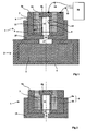
- a safety initiation component 1 is fixed by appropriate means (not shown) to an explosive charge 2 comprising an explosive 3 disposed in an envelope 4.
- the explosive charge will for example be a hexogen detonation relay in the powdered or compressed state.
- the component 1 comprises at least two electrodes 5a and 5b which are connected by a conductive fuse 6 and separated by an insulating tube 7 having an axial bore 14.
- a first electrode 5a or peripheral electrode, has a cylindrical wall 8 and a bottom 9 pierced with an axial hole 10.
- the insulating tube 7 has, at an upper face, a countersink 12 inside which is disposed the second electrode 5b, or axial electrode.
- the insulating tube 7 delimits an internal volume 13 which receives the fuse 6.
- the latter here has the shape of a tube which is applied against the inner surface of the bore 14 of the insulating tube 7 and which is wedged between the axial electrode 5b and the bottom 9 of the peripheral electrode 5a.
- the peripheral electrode 5a is disposed in a support 15 which may be made of an insulating material, for example polyamide.
- This support has an axial hole 16, or barrel, disposed in the extension of the axial hole 10 of the electrode 5a and whose diameter is less than or equal to that of the hole 10.
- the fuse 6 is made of a plasmagenic material that is to say a material supplying gases at high temperature (greater than 15,000 K) and having a strong electron density (greater than 10 18 electrons / cm3) when an electrical current of at least 5000 amperes passes through it.
- the electrodes 5a, 5b and the insulating tube 7 thus form a plasma torch whose internal volume 13 is separated from the recipient explosive 3 by the barrel 16.
- the barrel 16 is arranged facing another hole 17 arranged in the casing 4 of the explosive charge 2.
- Component 1 is a reduced-size plasma torch (or "micro-torch”). It has dimensions that are chosen low enough that it can generate a plasma when it receives a starting voltage of less than or equal to 600 volts and that it is supplied with electrical energy less than or equal to 5000 Joules.
- a micro torch is described as an ignition component in the patent EP905470 to which we can refer. It has dimensions of the order of 6 to 10 mm long for 5 to 10 mm in diameter.
- the fuse is here made in the form of a tubular layer, and clamped between the two electrodes 5a and 5b.
- the plasmagenic material will comprise at least one conductive material associated with at least one energetic material or capable of reacting with the conductive material.
- energetic material is meant a material capable of supplying chemical energy in the form of a flame when it is initiated by the joule effect generated by the passage of the current in the conductive material with which it is intimately associated.
- reactive material or capable of reacting with the conductive material is meant a material, inert in isolation, but capable of reacting chemically with the conductive material during the heating thereof by the Joule effect. Chemical energy is then provided by this reaction in the form of a flame.
- the conductive material may consist of carbon or a metal such as copper, aluminum, silver or magnesium.
- the energetic material or capable of reacting with the conductive material may be chosen from the following compounds or compositions:
- Copper oxide polytetrafluoroethylene; chlorofluoroethylene copolymer; polytetrafluoroethylene / chlorofluoroethylene copolymer; Magnesium / polytetrafluoroethylene / chlorofluoroethylene copolymer; Boron / Nitrate potassium; film or film of plasticized nitrocellulose; polyvinyl nitrate; polyoxymethylene; Trifluoroethylene chloride; polyvinyl chloride; Trifluoroethylene chloride; polysulfone; polyvinylidene fluoride.
- the energetic materials are the compositions: Magnesium / polytetrafluoroethylene / chlorofluoroethylene copolymer; Boron / potassium nitrate; film or film of plasticized nitrocellulose; polyvinyl nitrate.
- Reactive materials with a conductive material are: Copper oxide; polytetrafluoroethylene, chlorofluoroethylene copolymer; polytetrafluoroethylene / chlorofluoroethylene copolymer; polyoxymethylene; Trifluoroethylene chloride; Polyvinyl chloride; polysulfone; Polyvinylidene fluoride
- the fuse tube 6 is formed by a homogeneous mixture comprising 85 to 95% by weight of conductive material and 5 to 15% by weight of an energetic material or capable of reacting with the conductive material.
- a fuse tube may be made with the following compositions:
- the sheet can be concretely made by mixing the metal (aluminum or magnesium) with a solution of polytetrafluoroethylene and chlorofluoroethylene copolymer in a suitable solvent, for example a ketone: cyclohexyl ketone (cyclohexane) or acetone.
- a suitable solvent for example a ketone: cyclohexyl ketone (cyclohexane) or acetone.
- a suitable solvent for example a ketone: cyclohexyl ketone (cyclohexane) or acetone.
- the component 1 is connected by conductors 18 and 19 to an electric generator 20.
- This generator is designed to be able to deliver an energy of 10 kJ to 1 mega-joule in the form of voltage pulses from 1000 volts to 20 kilo volts.
- Such a generator is conventional and comprises for example capacitors, an inductor, thyristors and a stabilized power supply.
- a small fraction of the energy supplied by the generator is used to initiate the fuse tube 6 by joule effect.
- the energetic material is then initiated or the reaction between the conductive material and the reactive material is initiated.
- a combustion flame fills the chamber 13.
- This flame is naturally formed of ionized atoms and molecules. It provides an electrical conduction of reduced resistance between the electrodes 5a and 5b which allows the maintenance of an electric arc between the electrodes.
- the chamber 13 ensures a confinement of the arc and the rise in pressure thus allowing the development of the plasma generated by the fuse tube 6.
- the plasma is ejected at a speed of the order of 3500 m / s.
- the shock will be all the more intense as the volume of the chamber 13 will be reduced.
- an ignition component having a plasma micro-torch delimiting a chamber 13 having a volume of approximately 15 mm 3 and comprising a fuse tube 2 mm in diameter, 0.1 mm in thickness, has been realized. having as composition one or the other of the compositions according to Examples 1 and 2.
- Such a component powered by a voltage pulse of 800 to 1000 volts with a maximum intensity of 10000 amperes, provided the detonation of an explosive relay of 11.5 mm diameter and 11.5 mm high made of hexogen / wax / graphite (relative mass proportions: 98/2/1).
- the gas pressure obtained at the output of the component is of the order of 1 GPa (1 gigapascal).
- the component according to the invention is of simpler manufacture than that of the known safety components or "slappers" since it does not require the production of a resistive bridge and that it does not implement pellet to project reduced size.
- the diameter of the chamber 13 (2 mm) is greater than that of the guns used in known “slappers" (whose diameter is generally less than 1 mm).
- the supply voltage is also lower (of the order of 1000 volts against nearly 3000 volts for known "slappers"). This greatly reduces insulation problems and thus facilitates the integration of the component in ammunition or automotive security systems.
- the electric power consumed is of the same order as for the known "slappers" (10 Mega Watts), the maximum intensity being also stronger (about 10 kilo Amperes).
- the component according to the invention is a safety component since the level of energy required for its initiation meets the requirements given by the standards: no pyrotechnic reaction for a pulse of less than 500 volts. It can therefore be used in a priming device devoid of pyrotechnic warp misalignment means.
- the figure 2 shows a priming component according to a second embodiment of the invention.
- component 1 has been shown alone without the explosive charge that it must initiate.
- the fuse 6 thus comprises a layer 6a of conductive material on which is deposited at least one layer 6b of an energetic material or capable of reacting with the conductive material.
- a fuse for example may be wound on itself a metal sheet on which was previously sprayed a mixture of glue and energy material or can react with the conductive material.
- the thickness of the metal layer will be of the order of 150 micrometers.
- the thickness of the (or) layers of energetic material will be of the order of 100 micrometers.
- the dimensions of the different layers will be such that 85 to 95% by weight of the material of the conductive layer will be associated with 5 to 15% by weight of the material or materials of the reactive layer or layers.
- a fuse will be made by winding an aluminum foil on which is deposited at least one layer of chlorofluoroethylene copolymer (known under the trademark Viton).
- the relative weight proportions will be 90% for aluminum and 10% for the chlorofluoroethylene copolymer.
- the fuse 6 is arranged so that the metal layer 6a is on the side of the insulating tube 7 and in contact with the two electrodes 5a and 5b.
- the passage of the current can thus be done through the conductive layer 6a which will ensure by joule the initiation of the reaction with the energy layer 6b thus the generation of the plasma.
- a component comprising a fuse having a layer 80 microns thick aluminum carrying a layer of 11 microns of chlorofluoroethylene copolymer (known under the trademark Viton) was made.
- the fuse is disposed in a chamber 13 of volume 15mm3 approximately.
- This component was able to initiate an explosive tablet as described above in response to a voltage pulse of 1000 volts for a maximum intensity of 10 kA.
- a component also comprising (as in the conventional "slapper” components) a projectable pellet.
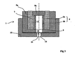
- the figure 3 shows such a component 1.
- the component 1 comprises two electrodes 5a and 5b which are connected by a fuse 6 associating a conductive layer 6a and an energetic layer 6b.
- This component differs from that of the figure 2 in that a pellet 21 is interposed between the annular rim 9 of the electrode 5a and the insulating support 15. This pellet thus separates the chamber 13 from the plasma torch and the barrel 16.
- the pellet 21 will be made of an electrical insulating material or covered with an insulating electrical layer. Such an arrangement makes it possible to avoid electric arc flashings directly between the axial electrode 5b and the wafer 21.
- the wafer may be made of a plastic material such as a polyimide (material known under the trademark Kapton). It will also make the pellet mica or metal (aluminum, titanium or steel). In the case of a metal pellet, it will be covered on both sides with an insulating material, for example a layer of insulating adhesive tape providing an electrical insulation level of at least 1000 volts (such insulators generally use an insulating layer of rubber or polyvinyl chloride or PVC).
- the diameter of the barrel 16 may vary between 1 and 4 mm, which is greater than the diameters of guns commonly used in slappers.
- components incorporating a fuse combining an aluminum layer and a layer of chlorofluoroethylene copolymer have been produced with the respective proportions by weight of 90% and 10% (total thickness of the fuse 100 micrometers).
- a projection pellet associated with a gun of diameter 2 or 4 mm pellet having a thickness of 30 to 120 microns for steel or 80 to 120 microns for Kapton. All components led to the initiation of an 11.5mm x 11.5mm hexogen tablet compressed to 160 Mega Pascals.
Landscapes
- Engineering & Computer Science (AREA)
- General Engineering & Computer Science (AREA)
- Fuses (AREA)
- Ceramic Products (AREA)
- Inorganic Fibers (AREA)
- Crystals, And After-Treatments Of Crystals (AREA)
- Plasma Technology (AREA)
- External Artificial Organs (AREA)
Claims (16)
- Sicherheits-Zündkomponente (1) umfassend wenigstens zwei Elektroden (5a,5b), die durch eine Schmelzsicherung (6) verbunden sind, und eine Öffnung oder Lauf (16), das die Schmelzsicherung von einer zu initiierenden Sprengstoffaufnahme (3) trennt, wobei die beiden Elektroden (5a,5b) durch ein isolierendes Rohr (7) getrennt sind, das ein inneres Volumen (13) abgrenzt, wobei Elektroden und isolierendes Rohr so einen Plasmabrenner bilden, dessen inneres Volumen (13) durch den Lauf (16) von der Sprengstoffaufnahme (3) getrennt wird, und wird dadurch gekennzeichnet, dass die Schmelzsicherung (6) aus einem Plasmamaterial hergestellt ist, das wenigstens ein leitfähiges Material umfasst, das mit wenigstens einem energetischen oder mit dem leitfähigen Material zu reagieren geeignetem Material verknüpft ist.
- Sicherheits-Zündkomponente nach Anspruch 1, dadurch gekennzeichnet, dass das leitfähige Material durch Kohlenstoff oder auch ein Metall gebildet wird.
- Sicherheits-Zündkomponente nach einem der Ansprüche 1 oder 2, dadurch gekennzeichnet, dass das energetische oder mit dem leitfähigen Material zu reagieren geeignete Material aus den folgenden Verbindungen oder Zusammensetzungen gewählt wird:Kupferoxid; Polytetrafluorethylen; Kopolymer von Chlorfluorethylen; Polytetrafluorethylen / Kopolymer von Chlorfluorethylen; Magnesium / Polytetrafluorethylen / Kopolymer von Chlorfluorethylen; Bor / Kaliumnitrat; Film oder Folie aus plastifizierter Nitrozellulose; Polyvinylnitrat; Polyoximethylen; Polychlorid von Trifluorethylen; Polyvinylchlorid; Polychlorid von Trifluorethylen; Polysulfon, Polyvinylidenfluorid.
- Sicherheits-Zündkomponente nach einem der Ansprüche 1 bis 3, dadurch gekennzeichnet, dass die Schmelzsicherung (6) aus einem homogenen Gemisch gebildet ist, das 85% bis 95% in Masse von Partikeln aus leitfähigem Material und 5% bis 15% in Masse eines energetischen oder auch mit dem leitfähigen Material zu reagieren geeigneten Materials verknüpft.
- Sicherheits-Zündkomponente nach Anspruch 4, dadurch gekennzeichnet, dass die schmelzbare Folie als Zusammensetzung aufweist:- 85% bis 95% in Masse von Aluminium- oder Magnesiumpulver,- 5% bis 15% in Masse einer Zusammensetzung, die Polytetrafluorethylen und Kopolymer von Chlorfluorethylen verknüpft.
- Sicherheits-Zündkomponente nach Anspruch 5, dadurch gekennzeichnet, dass die schmelzbare Folie als Zusammensetzung aufweist:- 90% in Masse von Aluminiumpulver,- 10% in Masse einer Zusammensetzung, die Polytetrafluorethylen und Kopolymer von Chlorfluorethylen verknüpft.
- Sicherheits-Zündkomponente nach Anspruch 5, dadurch gekennzeichnet, dass die schmelzbare Folie als Zusammensetzung aufweist:- 90% in Masse von Magnesiumpulver,- 10% in Masse einer Zusammensetzung, die Polytetrafluorethylen und Kopolymer von Chlorfluorethylen verknüpft.
- Sicherheits-Zündkomponente nach einem der Ansprüche 1 bis 3, dadurch gekennzeichnet, dass die Schmelzsicherung (6) wenigstens eine Schicht (6b) von energetischen oder auch mit dem leitfähigen Material zu reagieren geeignetem Material umfasst, die auf wenigstens einem Teil einer Schicht (6a) von leitfähigem Material abgelegt ist.
- Sicherheits-Zündkomponente nach Anspruch 8, dadurch gekennzeichnet, dass die Schmelzsicherung (6) wenigstens eine leitfähige Schicht (6a) aus Aluminium oder Magnesium umfasst, auf der wenigstens eine reaktive Schicht (6b) aus Polytetrafluorethylen oder Nitrozellulose oder Polyvinylnitrat oder Kupferoxid oder Kopolymer von Chlorfluorethylen oder Polyoximethylen oder Polychlorid von Trifluorethylen oder Polysulfon oder Polyvinylidenfluorid abgelegt ist.
- Sicherheits-Zündkomponente nach Anspruch 9, dadurch gekennzeichnet, dass die Dimensionen der verschiedenen Schichten werden so gewählt, dass 85 bis 95% in Masse von Material der leitfähigen Schicht mit 5 bis 15% in Masse des oder der Materialien der reaktiven Schicht oder Schichten verknüpft werden.
- Sicherheits-Zündkomponente nach Anspruch 10, dadurch gekennzeichnet, dass die Schmelzsicherung wenigstens eine Aluminiumschicht und wenigstens eine Schicht aus Kopolymer von Chlorfluorethylen umfasst.
- Sicherheits-Zündkomponente nach Anspruch 10, dadurch gekennzeichnet, dass die Schmelzsicherung wenigstens eine Magnesiumschicht und wenigstens eine Schicht aus Kopolymer von Chlorfluorethylen umfasst.
- Sicherheits-Zündkomponente nach Anspruch 10, dadurch gekennzeichnet, dass die Schmelzsicherung wenigstens eine Magnesiumschicht und wenigstens eine Schicht aus Polytetrafluorethylen umfasst.
- Sicherheits-Zündkomponente nach einem der Ansprüche 1 bis 13, dadurch gekennzeichnet, dass sie ein zu schleuderndes Plättchen (21) umfasst, das zwischen dem Brenner und dem Lauf (16) eingeklemmt ist.
- Sicherheits-Zündkomponente nach Anspruch 14, dadurch gekennzeichnet, dass das Plättchen (21) aus einem elektrisch isolierenden Material ausgeführt oder mit einer elektrisch isolierenden Schicht beschichtet ist.
- Sicherheits-Zündkomponente nach Anspruch 15, dadurch gekennzeichnet, dass das Plättchen (21) einen Durchmesser aufweist, der zwischen 1 mm und 4 mm liegt, und eine Dicke, die zwischen 20 und 200 Mikrometer liegt.
Applications Claiming Priority (2)
| Application Number | Priority Date | Filing Date | Title |
|---|---|---|---|
| FR0206591A FR2840401B1 (fr) | 2002-05-29 | 2002-05-29 | Composant d'amorcage de securite a torche a plasma |
| FR0206591 | 2002-05-29 |
Publications (2)
| Publication Number | Publication Date |
|---|---|
| EP1367355A1 EP1367355A1 (de) | 2003-12-03 |
| EP1367355B1 true EP1367355B1 (de) | 2008-05-14 |
Family
ID=29415146
Family Applications (1)
| Application Number | Title | Priority Date | Filing Date |
|---|---|---|---|
| EP03291267A Expired - Lifetime EP1367355B1 (de) | 2002-05-29 | 2003-05-27 | Sicherheitsplasmazündelement |
Country Status (4)
| Country | Link |
|---|---|
| EP (1) | EP1367355B1 (de) |
| AT (1) | ATE395571T1 (de) |
| DE (1) | DE60320892D1 (de) |
| FR (1) | FR2840401B1 (de) |
Family Cites Families (4)
| Publication number | Priority date | Publication date | Assignee | Title |
|---|---|---|---|---|
| US4788913A (en) * | 1971-06-02 | 1988-12-06 | The United States Of America As Represented By The United States Department Of Energy | Flying-plate detonator using a high-density high explosive |
| GB2100395B (en) * | 1981-06-15 | 1984-08-01 | Secr Defence | Pyrotechnic devices |
| FR2669725B1 (fr) * | 1990-11-27 | 1994-10-07 | Thomson Brandt Armements | Detonateur pyrotechnique a connexions coaxiales. |
| US6298784B1 (en) * | 1999-10-27 | 2001-10-09 | Talley Defense Systems, Inc. | Heat transfer delay |
-
2002
- 2002-05-29 FR FR0206591A patent/FR2840401B1/fr not_active Expired - Fee Related
-
2003
- 2003-05-27 EP EP03291267A patent/EP1367355B1/de not_active Expired - Lifetime
- 2003-05-27 AT AT03291267T patent/ATE395571T1/de not_active IP Right Cessation
- 2003-05-27 DE DE60320892T patent/DE60320892D1/de not_active Expired - Lifetime
Also Published As
| Publication number | Publication date |
|---|---|
| FR2840401B1 (fr) | 2004-07-16 |
| FR2840401A1 (fr) | 2003-12-05 |
| ATE395571T1 (de) | 2008-05-15 |
| DE60320892D1 (de) | 2008-06-26 |
| EP1367355A1 (de) | 2003-12-03 |
Similar Documents
| Publication | Publication Date | Title |
|---|---|---|
| EP1185833B1 (de) | Plasmabrenner, enthaltend eine reaktive zündersicherung und einen solchen brenner enthaltendes zündrohr | |
| EP1030159B1 (de) | Elektropyrotechnischer Zünder mit erhöhter Zündsicherheit | |
| EP0905470B1 (de) | Zündbauelement für pyrotechnische Zusammensetzungen oder Treibladungen | |
| US7574960B1 (en) | Ignition element | |
| EP2132429A2 (de) | Elektrolytzünder für raketenmotoren mit monopropellanten | |
| FR2914368A1 (fr) | Allumeur electrolytique pour moteur-fusee a ergols liquides | |
| EP0468838B1 (de) | Zündsystem für eine pyrotechnische Zusammensetzung | |
| FR2807611A1 (fr) | Torche plasma comportant des electrodes separees par un entrefer et allumeur incorporant une telle torche | |
| EP1306643B1 (de) | Optischer Zünder mit niedriger Energie | |
| EP2406577B1 (de) | Gasgenerator mit nicht-pyrotechnischer erregervorrichtung | |
| EP1273875B1 (de) | Anzünder für Treibladungen | |
| EP1367355B1 (de) | Sicherheitsplasmazündelement | |
| EP0076210B1 (de) | Elektrische Brückenzünder für pyrotechnische Ladungen | |
| EP1367356B1 (de) | Sicherheitszündelement | |
| EP1067354B1 (de) | Zünder für eine Explosivladung | |
| EP0296962A1 (de) | Anzünder für einen pyrotechnischen Generator | |
| EP2508838B1 (de) | Zünder, pyrotechnische Komponente und Herstellungsverfahren einer solchen pyrotechnischen Komponente | |
| US11725896B2 (en) | Repeatable plasma generator | |
| EP1403611A1 (de) | Doppelanzünder und Zündverfahren in dem ein solcher Anzünder verwendet wird | |
| EP0592292B1 (de) | Elektrischer Zünder mit leitender Zusammensetzung | |
| KR19980703195A (ko) | 전기열 화학 카트리지 | |
| EP0663376A1 (de) | Brandzusammensetzung und Brandgeschoss das diese Zusammensetzung verbreitet | |
| JPH08226791A (ja) | 飛翔体投射装置 |
Legal Events
| Date | Code | Title | Description |
|---|---|---|---|
| PUAI | Public reference made under article 153(3) epc to a published international application that has entered the european phase |
Free format text: ORIGINAL CODE: 0009012 |
|
| AK | Designated contracting states |
Kind code of ref document: A1 Designated state(s): AT BE BG CH CY CZ DE DK EE ES FI FR GB GR HU IE IT LI LU MC NL PT RO SE SI SK TR |
|
| AX | Request for extension of the european patent |
Extension state: AL LT LV MK |
|
| 17P | Request for examination filed |
Effective date: 20031222 |
|
| AKX | Designation fees paid |
Designated state(s): AT BE BG CH CY CZ DE DK EE ES FI FR GB GR HU IE IT LI LU MC NL PT RO SE SI SK TR |
|
| 17Q | First examination report despatched |
Effective date: 20060628 |
|
| RAP1 | Party data changed (applicant data changed or rights of an application transferred) |
Owner name: NEXTER MUNITIONS |
|
| GRAP | Despatch of communication of intention to grant a patent |
Free format text: ORIGINAL CODE: EPIDOSNIGR1 |
|
| GRAS | Grant fee paid |
Free format text: ORIGINAL CODE: EPIDOSNIGR3 |
|
| GRAA | (expected) grant |
Free format text: ORIGINAL CODE: 0009210 |
|
| AK | Designated contracting states |
Kind code of ref document: B1 Designated state(s): AT BE BG CH CY CZ DE DK EE ES FI FR GB GR HU IE IT LI LU MC NL PT RO SE SI SK TR |
|
| REG | Reference to a national code |
Ref country code: GB Ref legal event code: FG4D Free format text: NOT ENGLISH |
|
| REG | Reference to a national code |
Ref country code: CH Ref legal event code: EP |
|
| REG | Reference to a national code |
Ref country code: IE Ref legal event code: FG4D |
|
| REG | Reference to a national code |
Ref country code: CH Ref legal event code: NV Representative=s name: ING. MARCO ZARDI C/O M. ZARDI & CO. S.A. |
|
| REF | Corresponds to: |
Ref document number: 60320892 Country of ref document: DE Date of ref document: 20080626 Kind code of ref document: P |
|
| REG | Reference to a national code |
Ref country code: SE Ref legal event code: TRGR |
|
| PG25 | Lapsed in a contracting state [announced via postgrant information from national office to epo] |
Ref country code: SI Free format text: LAPSE BECAUSE OF FAILURE TO SUBMIT A TRANSLATION OF THE DESCRIPTION OR TO PAY THE FEE WITHIN THE PRESCRIBED TIME-LIMIT Effective date: 20080514 |
|
| PG25 | Lapsed in a contracting state [announced via postgrant information from national office to epo] |
Ref country code: ES Free format text: LAPSE BECAUSE OF FAILURE TO SUBMIT A TRANSLATION OF THE DESCRIPTION OR TO PAY THE FEE WITHIN THE PRESCRIBED TIME-LIMIT Effective date: 20080825 Ref country code: FI Free format text: LAPSE BECAUSE OF FAILURE TO SUBMIT A TRANSLATION OF THE DESCRIPTION OR TO PAY THE FEE WITHIN THE PRESCRIBED TIME-LIMIT Effective date: 20080514 |
|
| NLV1 | Nl: lapsed or annulled due to failure to fulfill the requirements of art. 29p and 29m of the patents act | ||
| PG25 | Lapsed in a contracting state [announced via postgrant information from national office to epo] |
Ref country code: AT Free format text: LAPSE BECAUSE OF FAILURE TO SUBMIT A TRANSLATION OF THE DESCRIPTION OR TO PAY THE FEE WITHIN THE PRESCRIBED TIME-LIMIT Effective date: 20080514 Ref country code: NL Free format text: LAPSE BECAUSE OF FAILURE TO SUBMIT A TRANSLATION OF THE DESCRIPTION OR TO PAY THE FEE WITHIN THE PRESCRIBED TIME-LIMIT Effective date: 20080514 |
|
| BERE | Be: lapsed |
Owner name: NEXTER MUNITIONS Effective date: 20080531 |
|
| PG25 | Lapsed in a contracting state [announced via postgrant information from national office to epo] |
Ref country code: MC Free format text: LAPSE BECAUSE OF NON-PAYMENT OF DUE FEES Effective date: 20080531 |
|
| REG | Reference to a national code |
Ref country code: IE Ref legal event code: FD4D |
|
| PG25 | Lapsed in a contracting state [announced via postgrant information from national office to epo] |
Ref country code: PT Free format text: LAPSE BECAUSE OF FAILURE TO SUBMIT A TRANSLATION OF THE DESCRIPTION OR TO PAY THE FEE WITHIN THE PRESCRIBED TIME-LIMIT Effective date: 20081014 Ref country code: DK Free format text: LAPSE BECAUSE OF FAILURE TO SUBMIT A TRANSLATION OF THE DESCRIPTION OR TO PAY THE FEE WITHIN THE PRESCRIBED TIME-LIMIT Effective date: 20080514 Ref country code: CZ Free format text: LAPSE BECAUSE OF FAILURE TO SUBMIT A TRANSLATION OF THE DESCRIPTION OR TO PAY THE FEE WITHIN THE PRESCRIBED TIME-LIMIT Effective date: 20080514 Ref country code: IE Free format text: LAPSE BECAUSE OF FAILURE TO SUBMIT A TRANSLATION OF THE DESCRIPTION OR TO PAY THE FEE WITHIN THE PRESCRIBED TIME-LIMIT Effective date: 20080514 |
|
| PG25 | Lapsed in a contracting state [announced via postgrant information from national office to epo] |
Ref country code: RO Free format text: LAPSE BECAUSE OF FAILURE TO SUBMIT A TRANSLATION OF THE DESCRIPTION OR TO PAY THE FEE WITHIN THE PRESCRIBED TIME-LIMIT Effective date: 20080514 Ref country code: SK Free format text: LAPSE BECAUSE OF FAILURE TO SUBMIT A TRANSLATION OF THE DESCRIPTION OR TO PAY THE FEE WITHIN THE PRESCRIBED TIME-LIMIT Effective date: 20080514 |
|
| PLBE | No opposition filed within time limit |
Free format text: ORIGINAL CODE: 0009261 |
|
| STAA | Information on the status of an ep patent application or granted ep patent |
Free format text: STATUS: NO OPPOSITION FILED WITHIN TIME LIMIT |
|
| PG25 | Lapsed in a contracting state [announced via postgrant information from national office to epo] |
Ref country code: BE Free format text: LAPSE BECAUSE OF NON-PAYMENT OF DUE FEES Effective date: 20080531 |
|
| 26N | No opposition filed |
Effective date: 20090217 |
|
| PG25 | Lapsed in a contracting state [announced via postgrant information from national office to epo] |
Ref country code: BG Free format text: LAPSE BECAUSE OF FAILURE TO SUBMIT A TRANSLATION OF THE DESCRIPTION OR TO PAY THE FEE WITHIN THE PRESCRIBED TIME-LIMIT Effective date: 20080814 Ref country code: EE Free format text: LAPSE BECAUSE OF FAILURE TO SUBMIT A TRANSLATION OF THE DESCRIPTION OR TO PAY THE FEE WITHIN THE PRESCRIBED TIME-LIMIT Effective date: 20080514 |
|
| PG25 | Lapsed in a contracting state [announced via postgrant information from national office to epo] |
Ref country code: CY Free format text: LAPSE BECAUSE OF FAILURE TO SUBMIT A TRANSLATION OF THE DESCRIPTION OR TO PAY THE FEE WITHIN THE PRESCRIBED TIME-LIMIT Effective date: 20080514 Ref country code: HU Free format text: LAPSE BECAUSE OF FAILURE TO SUBMIT A TRANSLATION OF THE DESCRIPTION OR TO PAY THE FEE WITHIN THE PRESCRIBED TIME-LIMIT Effective date: 20081115 Ref country code: LU Free format text: LAPSE BECAUSE OF NON-PAYMENT OF DUE FEES Effective date: 20080527 |
|
| PG25 | Lapsed in a contracting state [announced via postgrant information from national office to epo] |
Ref country code: TR Free format text: LAPSE BECAUSE OF FAILURE TO SUBMIT A TRANSLATION OF THE DESCRIPTION OR TO PAY THE FEE WITHIN THE PRESCRIBED TIME-LIMIT Effective date: 20080514 |
|
| PG25 | Lapsed in a contracting state [announced via postgrant information from national office to epo] |
Ref country code: GR Free format text: LAPSE BECAUSE OF FAILURE TO SUBMIT A TRANSLATION OF THE DESCRIPTION OR TO PAY THE FEE WITHIN THE PRESCRIBED TIME-LIMIT Effective date: 20080815 |
|
| PGFP | Annual fee paid to national office [announced via postgrant information from national office to epo] |
Ref country code: SE Payment date: 20110426 Year of fee payment: 9 Ref country code: CH Payment date: 20110427 Year of fee payment: 9 |
|
| PGFP | Annual fee paid to national office [announced via postgrant information from national office to epo] |
Ref country code: GB Payment date: 20110503 Year of fee payment: 9 |
|
| PGFP | Annual fee paid to national office [announced via postgrant information from national office to epo] |
Ref country code: IT Payment date: 20110423 Year of fee payment: 9 Ref country code: DE Payment date: 20110505 Year of fee payment: 9 |
|
| REG | Reference to a national code |
Ref country code: CH Ref legal event code: PL |
|
| REG | Reference to a national code |
Ref country code: SE Ref legal event code: EUG |
|
| GBPC | Gb: european patent ceased through non-payment of renewal fee |
Effective date: 20120527 |
|
| PG25 | Lapsed in a contracting state [announced via postgrant information from national office to epo] |
Ref country code: CH Free format text: LAPSE BECAUSE OF NON-PAYMENT OF DUE FEES Effective date: 20120531 Ref country code: LI Free format text: LAPSE BECAUSE OF NON-PAYMENT OF DUE FEES Effective date: 20120531 |
|
| PG25 | Lapsed in a contracting state [announced via postgrant information from national office to epo] |
Ref country code: IT Free format text: LAPSE BECAUSE OF NON-PAYMENT OF DUE FEES Effective date: 20120527 Ref country code: SE Free format text: LAPSE BECAUSE OF NON-PAYMENT OF DUE FEES Effective date: 20120528 |
|
| REG | Reference to a national code |
Ref country code: DE Ref legal event code: R119 Ref document number: 60320892 Country of ref document: DE Effective date: 20121201 |
|
| PG25 | Lapsed in a contracting state [announced via postgrant information from national office to epo] |
Ref country code: GB Free format text: LAPSE BECAUSE OF NON-PAYMENT OF DUE FEES Effective date: 20120527 |
|
| PG25 | Lapsed in a contracting state [announced via postgrant information from national office to epo] |
Ref country code: DE Free format text: LAPSE BECAUSE OF NON-PAYMENT OF DUE FEES Effective date: 20121201 |
|
| REG | Reference to a national code |
Ref country code: FR Ref legal event code: PLFP Year of fee payment: 14 |
|
| REG | Reference to a national code |
Ref country code: FR Ref legal event code: PLFP Year of fee payment: 15 |
|
| REG | Reference to a national code |
Ref country code: FR Ref legal event code: PLFP Year of fee payment: 16 |
|
| PGFP | Annual fee paid to national office [announced via postgrant information from national office to epo] |
Ref country code: FR Payment date: 20200422 Year of fee payment: 18 |
|
| PG25 | Lapsed in a contracting state [announced via postgrant information from national office to epo] |
Ref country code: FR Free format text: LAPSE BECAUSE OF NON-PAYMENT OF DUE FEES Effective date: 20210531 |