EP1367347A2 - Device for wood treatment - Google Patents
Device for wood treatment Download PDFInfo
- Publication number
- EP1367347A2 EP1367347A2 EP03076319A EP03076319A EP1367347A2 EP 1367347 A2 EP1367347 A2 EP 1367347A2 EP 03076319 A EP03076319 A EP 03076319A EP 03076319 A EP03076319 A EP 03076319A EP 1367347 A2 EP1367347 A2 EP 1367347A2
- Authority
- EP
- European Patent Office
- Prior art keywords
- machine
- drying
- components
- flash period
- treatment
- Prior art date
- Legal status (The legal status is an assumption and is not a legal conclusion. Google has not performed a legal analysis and makes no representation as to the accuracy of the status listed.)
- Granted
Links
Images


Classifications
-
- F—MECHANICAL ENGINEERING; LIGHTING; HEATING; WEAPONS; BLASTING
- F26—DRYING
- F26B—DRYING SOLID MATERIALS OR OBJECTS BY REMOVING LIQUID THEREFROM
- F26B15/00—Machines or apparatus for drying objects with progressive movement; Machines or apparatus with progressive movement for drying batches of material in compact form
- F26B15/10—Machines or apparatus for drying objects with progressive movement; Machines or apparatus with progressive movement for drying batches of material in compact form with movement in a path composed of one or more straight lines, e.g. compound, the movement being in alternate horizontal and vertical directions
- F26B15/12—Machines or apparatus for drying objects with progressive movement; Machines or apparatus with progressive movement for drying batches of material in compact form with movement in a path composed of one or more straight lines, e.g. compound, the movement being in alternate horizontal and vertical directions the lines being all horizontal or slightly inclined
- F26B15/122—Machines or apparatus for drying objects with progressive movement; Machines or apparatus with progressive movement for drying batches of material in compact form with movement in a path composed of one or more straight lines, e.g. compound, the movement being in alternate horizontal and vertical directions the lines being all horizontal or slightly inclined the objects or batches of material being carried by transversely moving rollers or rods which may rotate
-
- F—MECHANICAL ENGINEERING; LIGHTING; HEATING; WEAPONS; BLASTING
- F26—DRYING
- F26B—DRYING SOLID MATERIALS OR OBJECTS BY REMOVING LIQUID THEREFROM
- F26B15/00—Machines or apparatus for drying objects with progressive movement; Machines or apparatus with progressive movement for drying batches of material in compact form
- F26B15/10—Machines or apparatus for drying objects with progressive movement; Machines or apparatus with progressive movement for drying batches of material in compact form with movement in a path composed of one or more straight lines, e.g. compound, the movement being in alternate horizontal and vertical directions
- F26B15/12—Machines or apparatus for drying objects with progressive movement; Machines or apparatus with progressive movement for drying batches of material in compact form with movement in a path composed of one or more straight lines, e.g. compound, the movement being in alternate horizontal and vertical directions the lines being all horizontal or slightly inclined
- F26B15/14—Machines or apparatus for drying objects with progressive movement; Machines or apparatus with progressive movement for drying batches of material in compact form with movement in a path composed of one or more straight lines, e.g. compound, the movement being in alternate horizontal and vertical directions the lines being all horizontal or slightly inclined the objects or batches of materials being carried by trays or racks or receptacles, which may be connected to endless chains or belts
-
- F—MECHANICAL ENGINEERING; LIGHTING; HEATING; WEAPONS; BLASTING
- F26—DRYING
- F26B—DRYING SOLID MATERIALS OR OBJECTS BY REMOVING LIQUID THEREFROM
- F26B3/00—Drying solid materials or objects by processes involving the application of heat
- F26B3/32—Drying solid materials or objects by processes involving the application of heat by development of heat within the materials or objects to be dried, e.g. by fermentation or other microbiological action
- F26B3/34—Drying solid materials or objects by processes involving the application of heat by development of heat within the materials or objects to be dried, e.g. by fermentation or other microbiological action by using electrical effects
- F26B3/347—Electromagnetic heating, e.g. induction heating or heating using microwave energy
-
- F—MECHANICAL ENGINEERING; LIGHTING; HEATING; WEAPONS; BLASTING
- F26—DRYING
- F26B—DRYING SOLID MATERIALS OR OBJECTS BY REMOVING LIQUID THEREFROM
- F26B2210/00—Drying processes and machines for solid objects characterised by the specific requirements of the drying goods
- F26B2210/14—Veneer, i.e. wood in thin sheets
-
- F—MECHANICAL ENGINEERING; LIGHTING; HEATING; WEAPONS; BLASTING
- F26—DRYING
- F26B—DRYING SOLID MATERIALS OR OBJECTS BY REMOVING LIQUID THEREFROM
- F26B2210/00—Drying processes and machines for solid objects characterised by the specific requirements of the drying goods
- F26B2210/16—Wood, e.g. lumber, timber
Definitions
- the present invention concerns a machine for the working of components on solid wood, fit to be obtained even with its by-products (HDF, MDF, etc.) and veneered, in particular for the flash period/drying of paints applied on these components, which are fit in case to be later assembled, including an environment where these components are placed for the process of the flash period/drying before proceeding to their assembling on furniture, walls and such.
- HDF by-products
- MDF etc.
- veneered in particular for the flash period/drying of paints applied on these components, which are fit in case to be later assembled, including an environment where these components are placed for the process of the flash period/drying before proceeding to their assembling on furniture, walls and such.
- furnaces consisting of tunnels, where these components are treated to achieve the flash period/drying of the paint, obtained with hot air currents or with exposure to infrared lamps or U.V. in an environment with controlled humidity.
- the problem the machine wants to solve, according to the invention is to speed up substantially the time necessary for the flash period/drying of cold-water paints on wood components, to reduce consequently the installation and the working costs of these components and, as far as possible, to simplify the flash period/drying process.
- this problem is solved by the machine, characterized by the use of electromagnetic radiations in the spectrum of 2.450 +/- 50 MHz for the flash period/drying of paint on these wood components, to obtain in this way:
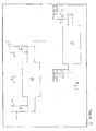
- the machine includes a device for the electromagnetic radiations emission, made up of two instruments 1,2. (Pic. 1,2).
- Such instruments are made up of two magnetrons, the magnetron 1 is positioned below magnetron 2, in that way both of them can cover . all the development in height of the painted wood elements to wither/dry.
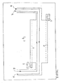
- the emission device comprises two waveguides too 3,4 (Pic 2), which are placed inside the machine (Pic. 2) provided with a lot of flans 5, so that they can have the effect to give out homogeneously the energy on the elements deriving from the radiant tubes.
- such radiation issued from devices 1,2 are suited to have a spectrum included in a range of 2450 +/-50 MHz., in such a way the wood components introduced in the machine are exposed to an electromagnetic field of multimodal type.
- the described machine is suited to carry out a flash period/drying process on wood elements (Pic 3) having a size included in a range from (10-25) cm., while for the treatment of wood elements of larger sizes (for example boards of various surfaces and thickness), a different machine is expected, provided with an adequate scaling in Kw/mq of the magnetron power and a consequent belt conveyor instead of a chain conveyor.
- the machine includes two electrical gear cases 6,7,: the first 6 (Pic. 1) is suited to power the magnetrons 1,2, while the second 7 is suited to power the electrical users for the machine working (motors for the elements dragging, pumps for the water circulation for shielding and cooling, etc.).
- the magnetron is placed at one end at of the waveguide, while the other end is closed by a cap, not shown in the drawings.
- the development of the waveguide, the distance of the magnetron from the cap, as well as the number and the development of the flaws F, are all elements which are determined during the planning of the machine, taking in consideration the performance requested to the machine, even with the purpose to optimize the homogeneity of the electromagnetic flux coming from the flows F.
- Pic.3 shows a section of the machine according to the invention, where it is schematically pointed out the device of the translation and rotation of the wood element to treat.
- the support and translation device of the elements 5 includes: an environment 9, a chain 10, a gear wheel 11, attached to a rack 12, to transmit to a support 13 of the element 5 a translation and a rotation movement, allowing to the same element to be subjected, in every point to the same strength of electromagnetic waves.
- the support 13 is linked to a bearing 16, linked fixedly to the gear wheel 11.
- the last one is attached to the rack 12 fixed to a wall 17.
- a particular configuration of the machine according to the invention is the so-called "open doors" (Pic.5,6), where the machine planimetry according to the invention can take on respectively a U (Pic.5) or a ⁇
- PVC tubes Inside the machine, according to the invention, there are some PVC tubes (Pic.3) for water circulation of shielding and cooling.
- a first module can concern the flash period/drying treatment after the painting (first painting phase). This first module can be eliminated, given the reduced thickness of such painting and the quickness of the respective flash period/drying process.
- a second module can be conceived for the flash period/drying treatment of priming (second painting phase).
- the machine is suitable also to a painting treatment based on the use of powder paints.
- a painting treatment based on the use of powder paints.
- micro flame or infrared rays systems for these the duration of the working circle is substantially longer than the expected duration of the machine, according to the invention.
Landscapes
- Engineering & Computer Science (AREA)
- Mechanical Engineering (AREA)
- General Engineering & Computer Science (AREA)
- Microbiology (AREA)
- Life Sciences & Earth Sciences (AREA)
- Electromagnetism (AREA)
- Health & Medical Sciences (AREA)
- Biomedical Technology (AREA)
- Biotechnology (AREA)
- Physics & Mathematics (AREA)
- Molecular Biology (AREA)
- Chemical And Physical Treatments For Wood And The Like (AREA)
- Drying Of Solid Materials (AREA)
- Dry Formation Of Fiberboard And The Like (AREA)
Abstract
Description
- The present invention concerns a machine for the working of components on solid wood, fit to be obtained even with its by-products (HDF, MDF, etc.) and veneered, in particular for the flash period/drying of paints applied on these components, which are fit in case to be later assembled, including an environment where these components are placed for the process of the flash period/drying before proceeding to their assembling on furniture, walls and such.
- The wood components destined to be used exactly as they are in the wood industry, or to be assembled on furniture, walls and such, are generally subjected to a painting treatment, articulated in several phases, each of them articulated in one or more passages:
- at first the painting (fit to colour the wood component),
- then the application of the filler paint and
- at last the final coat of the flat paint.
- Till now th paints used on wood components, expected the presence of . chemical solvents, which had the advantage to take short time for . the flash period/drying of the treatment, but polluted both the work and the external environment, because of the fumes and the draining of paint waste.
- To reduce the environmental impact, it was decided to turn to the use of cold-water paints instead of paints with chemical solvents; the first ones do not pollute and are more easily used than the second ones , but present the disadvantage to request a considerably longer time than the paints with chemical solvents for the flash period/drying and therefore a decidedly higher cost to complete the painting process.
- At the moment, for the flash period/drying of wood components treated with cold-water paints, there are furnaces consisting of tunnels, where these components are treated to achieve the flash period/drying of the paint, obtained with hot air currents or with exposure to infrared lamps or U.V. in an environment with controlled humidity.
- The disadvantage of this process is caused by the installation and running expenses of these furnaces, but most of all by the dimensions of the plant and by the time necessary for the treatment.
- The problem the machine wants to solve, according to the invention, is to speed up substantially the time necessary for the flash period/drying of cold-water paints on wood components, to reduce consequently the installation and the working costs of these components and, as far as possible, to simplify the flash period/drying process.
- According to the invention, this problem is solved by the machine, characterized by the use of electromagnetic radiations in the spectrum of 2.450 +/- 50 MHz for the flash period/drying of paint on these wood components, to obtain in this way:
- a substantial reduction of the time employed for the flash period/drying of these paints on these components,
- a substantial reduction of the plant expenses, even because of the small dimensions and because of the substantial elimination of the insulating material;
- a substantially reliable result;
- times are reduced to about a fiftieth of the ones requested from the normal processes of flash period/drying of the treatment on components treated with cold-water paints and, consequently, reduced expenses of working for such process;
- the elimination of additional sources of energy, necessary to air-condition the environment of the flash period/drying of components treated with cold-water paints and,
- finally, in case of wood components are treated with paints base on chemical solvents, a substantial elimination of pollution elements for fumes and industrial waste,
- while, in case of wood components treated with cold-water paints, the flash period/drying of the paint (obtained in tunnels with hot air currents, or with exposure to infrared or U.V. lamps in an environment with controlled humidity) is achieved with plants whose installation and running expenses, as well as the plant sizes and the time necessary for the treatment are substantially reduced.
- These and other characteristics will be clear from the following description and the enclosed drawings where:
- Pic. 1 shows a plan view of the machine according to the invention;
- Pic.2 shows a lateral view of the same machine;
- Pic.3 shows a sectional view according to the lines A-A of Pic. 1;
- Pic.4 shows a waveguide of the same machine;
- Pic.5 shows a first alternative solution of the waveguide of the machine according to the invention;
- Pic.6 shows a second alternative solution of waveguide while
- Pic.7 shows a third alternative solution of waveguide of the machine according to the invention.
-
- According to the invention the machine includes a device for the electromagnetic radiations emission, made up of two
instruments - Such instruments are made up of two magnetrons, the
magnetron 1 is positioned belowmagnetron 2, in that way both of them can cover . all the development in height of the painted wood elements to wither/dry. - It is necessary to underline that, even in the presence of wood components with a substantial longitudinal development, the experience shows that only one magnetron can be sufficient to distribute homogeneously the energy on the components to treat.
- The emission device comprises two waveguides too 3,4 (Pic 2), which are placed inside the machine (Pic. 2) provided with a lot of flans 5, so that they can have the effect to give out homogeneously the energy on the elements deriving from the radiant tubes.
- As it will be possible to see further on, such radiation issued from
devices - The described machine is suited to carry out a flash period/drying process on wood elements (Pic 3) having a size included in a range from (10-25) cm., while for the treatment of wood elements of larger sizes (for example boards of various surfaces and thickness), a different machine is expected, provided with an adequate scaling in Kw/mq of the magnetron power and a consequent belt conveyor instead of a chain conveyor.
- To get to this scaling, every time there are tests on a prototype provided with sufficient flexibility to set in this way the optimum Kw/mq of power on surface, necessary to treat the wood elements 5.
- According to the invention the machine includes two
electrical gear cases magnetrons - As everybody knows, the magnetron is placed at one end at of the waveguide, while the other end is closed by a cap, not shown in the drawings. The development of the waveguide, the distance of the magnetron from the cap, as well as the number and the development of the flaws F, are all elements which are determined during the planning of the machine, taking in consideration the performance requested to the machine, even with the purpose to optimize the homogeneity of the electromagnetic flux coming from the flows F. Pic.3 shows a section of the machine according to the invention, where it is schematically pointed out the device of the translation and rotation of the wood element to treat.
- The support and translation device of the elements 5 includes: an environment 9, a
chain 10, a gear wheel 11, attached to arack 12, to transmit to asupport 13 of the element 5 a translation and a rotation movement, allowing to the same element to be subjected, in every point to the same strength of electromagnetic waves. - The
support 13 is linked to a bearing 16, linked fixedly to the gear wheel 11. - The last one is attached to the
rack 12 fixed to awall 17. - A particular configuration of the machine according to the invention is the so-called "open doors" (Pic.5,6), where the machine planimetry according to the invention can take on respectively a U (Pic.5) or a Ω
- (Pic.6) configuration. In Pic.5 the waveguides and then the resonance cavities are placed in an internal
straight section 18 of the machine, preceded and followed byattenuation sections 19 including radioabsorbent panels 20, distributed around the resonance cavities, offering the advantage to attenuate progressively the electromagnetic field in the central section of the machine and uniting contemporaneously the advantage to contain the longitudinal dimensions of the machine. - In Pic. 6 the waveguides and then the resonance cavities are positioned in an internal
straight section 18 of the machine, preceded and followed byattenuation segments 21,22, even here provided with radioabsorbent panels 23. It is also possible to think (Pic. 7) to a route there A and back R in the same furnace, with separated chains of dragging. - Inside the machine, according to the invention, there are some PVC tubes (Pic.3) for water circulation of shielding and cooling.
- The dislocation of such tubes concerns particularly critical points for the protection against electromagnet radiation.
- Concerning the machine layout, this can be conceived in a series of modules, in series one compared to the other, each one substantially analogous to the module represented in Pic. 1.
- For example, a first module can concern the flash period/drying treatment after the painting (first painting phase). This first module can be eliminated, given the reduced thickness of such painting and the quickness of the respective flash period/drying process.
- A second module can be conceived for the flash period/drying treatment of priming (second painting phase).
- At the exit of such module, it can be a sanding process and the application of the final coat of flat paint and then the entrance in a third module for the final flash period/drying treatment. Between one module and the other, there is the presence of machinery necessary to set going the various painting phases.
- From what already described, the advantages of the machine come out even in the plurality of versions that make it suitable for different work conditions (dimensions of the wood elements to treat, processes articulations, adaptation of different configurations of the waveguides, etc.).
- Such advantages can be summarized in this way:
- a substantial reduction of the time employed for the flash period/drying of these paints on such components,
- a substantial reduction of the plant cost, even because of its reduced dimensions and of the substantial elimination of the insulating material;
- a substantially reliable result;
- really reduced times to about a fiftieth in comparison to the requested times for the normal flash period/drying processes of the treatment on components treated with cold-water paints and, consequently, reduced costs of working for such process;
- the elimination of additional power sources necessary to air-condition the flash period/drying environment of components treated with cold-water paints,
- in case the wood components are treated with paints made of chemical solvents, there is a substantial elimination of pollution elements for fumes and industrial waste, and at last
- in case of wood components treated with cold-water paints, the flash period/drying of the paint (till now obtained in tunnels with hot air currents, or with exposure to infrared or U.V. lamps in a humidity controlled environment) is now obtained with systems whose installation and running expenses, and also the plant sizes and the requested time for the treatment are substantially reduced.
- It is necessary to underline that the machine, according to the invention, is suitable also to a painting treatment based on the use of powder paints. With such treatment, there is today the use of micro flame or infrared rays systems, for these the duration of the working circle is substantially longer than the expected duration of the machine, according to the invention.
- The advantage to use the machine, according to the invention, instead of micro flame or infrared rays systems, is given from the result of an optimum homogenization and compactness of the powder paint treatment.
Claims (12)
- Machine for the working of components (5) on solid wood, fit to be obtained even with its by-products (HDF, MDF, etc.) and veneered, in particular for the flash period/drying of paints applied on these components, which are fit in case to be later assembled, including an environment (9) where these components (5) are placed for the process of the flash period/drying before proceeding to their assembling on furniture, walls and such, characterized by the use of electromagnetic radiations in the spectrum of 2450 +/-50 MHz for the flash period/drying of paint on these wood components, so that these components are subjected to an electromagnetic field of multimodal type, obtaining:a substantial reduction of the time employed for the flash period/drying of these paints on such components,a substantial reduction of the plant expenses, even because of the small dimensions and because of the substantial eliminations of the insulating material;a substantially reliable result;times are reduced to about a fiftieth of the ones requested from the normal processes of flash period/drying of the treatment on components treated with cold-water paints and, consequently, reduced expenses of working for such process;the elimination of additional sources of energy, necessary to air-condition the environment of the flash period/drying of components treated with cold-water paints,in case wood components are treated with paints based on chemical solvents, a substantial elimination of pollution elements for fumes and industrial waste,finally, in case of wood components treated with cold-water paints, the flash period/drying of the paint ( till now obtained in tunnels with hot air currents, or with exposure to infrared or U.V. lamps in an environment with controlled humidity) is achieved with plants whose installation and running expenses, as well as the plant sizes and the time necessary for the treatment are substantially reduced.
- Machine as in 1, characterized by two waveguides (3,4) placed inside the machine and provided a lot of flaws (F), so that they can have the effect to give out homogeneously on the elements to treat, the energy deriving from the radiant tubes.
- Machine as in 1,2 characterized from the treatment of such elements (5) conditioned by the dimensions of the same elements, in the sense that the instruments power (1,2) in Kw/mq of surface power is dimensioned taking in consideration such sizes.
- Machine as in 2, characterizes from what the development of such waveguides (3,4), the number and the flaws development (F), the distance of the instruments (1,2) from the cap of the waveguides (3,4) all operate for the performances requested by the machine, even for the purpose to optimize the homogeneity of the electromagnetic flux coming out from the flaws (F).
- Machine as in the precedent claims, characterized by a support (9,10,11,12,13,16) of the elements (5) to transmit to such elements a translation and a rotation movement, in order to let the element (5) to be subjected in every point to the same intensity of electromagnetic waves.
- Machine as in 5, characterized from what the support includes: an environment 9, a chain (10) for the elements dragging (5), a gear wheel (11) attached to a rack (12) to transmit to a support (13) of the element (5) a translation and a rotation movement so that the same element is subjected in every point to the same intensity of the electromagnetic waves, and a bearing (16) linked fixedly to the gear wheel (11).
- Machine as in 1, characterized from the so-called "open doors" type of the same machine, where the waveguides (3,4) are suited to take on respectively a "U" or "Ω" configuration in order to undergo a substantially gradual attenuation at the exit of the electromagnetic waves, such "U" configuration is expected so that the waveguides and the resonance cavities are placed in an internal straight section (18) of the machine, preceded and followed by attenuation sections (19) with radio absorbent panels (2), so to progressively attenuate the electromagnetic field in the central part of the machine and in such a way to include substantially the longitudinal dimensions of the machine.
- Machine as in 7, characterized from waveguides and resonance cavities which are placed in a straight section (18) of the machine, preceded and followed by attenuation sections (21,22) provided with radio absorbent panels (23) so to progressively attenuate the electromagnetic field in the central part of the machine and in such a way include substantially the longitudinal dimensions of the machine.
- Machine as in 1, conceived in a series of modules, in series one compared to the other, a first module concerns the flash period/drying treatment after the painting (first painting phase), this first module can be eliminated, given the reduced thickness of such painting and quickness of the respective flash period/drying process, a second module can be conceived for the flash period/drying treatment of priming (second painting phase), at the exit of this second module there can be a sanding process and the application of the final coat of flat paint and then the entrance in a third module for the application of the final coat of flat paint (third painting phase) for the flash period/drying treatment.
- Machine as in the precedent claims, characterizes by a plurality of PVC tubes (18) for the water circulation for shielding from electromagnetic guides and of cooling.
- Machine as in 1, characterized from its performance to a painting treatment based on the use of powder paints with a substantial advantage in comparison to micro flame or infrared rays systems, the advantage of a substantially optimum homogenisation and compactness of the result obtained from the treatment of powder paint.
- Machine as described, shown in the drawings and object of the claims 1-11.
Applications Claiming Priority (2)
| Application Number | Priority Date | Filing Date | Title |
|---|---|---|---|
| IT2002PN000028A ITPN20020028A1 (en) | 2002-05-07 | 2002-05-07 | WOODWORKING MACHINE. |
| ITPN20020028 | 2002-05-07 |
Publications (3)
| Publication Number | Publication Date |
|---|---|
| EP1367347A2 true EP1367347A2 (en) | 2003-12-03 |
| EP1367347A3 EP1367347A3 (en) | 2006-08-16 |
| EP1367347B1 EP1367347B1 (en) | 2012-04-18 |
Family
ID=29416374
Family Applications (1)
| Application Number | Title | Priority Date | Filing Date |
|---|---|---|---|
| EP03076319A Expired - Lifetime EP1367347B1 (en) | 2002-05-07 | 2003-05-07 | Device for wood treatment |
Country Status (3)
| Country | Link |
|---|---|
| EP (1) | EP1367347B1 (en) |
| AT (1) | ATE554358T1 (en) |
| IT (1) | ITPN20020028A1 (en) |
Cited By (2)
| Publication number | Priority date | Publication date | Assignee | Title |
|---|---|---|---|---|
| EP1934543A4 (en) * | 2005-09-22 | 2013-05-15 | Eastman Chem Co | Microwave reactor having a slotted array waveguide |
| EP1926957A4 (en) * | 2005-09-22 | 2013-05-15 | Eastman Chem Co | Microwave reactor having a slotted array waveguide coupled to a waveguide bend |
Families Citing this family (1)
| Publication number | Priority date | Publication date | Assignee | Title |
|---|---|---|---|---|
| RU2596082C2 (en) * | 2014-12-30 | 2016-08-27 | Федеральное государственное автономное образовательное учреждение высшего профессионального образования "Северный (Арктический) федеральный университет имени М.В. Ломоносова" (САФУ) | Plant for drying wood in microwave field |
Citations (1)
| Publication number | Priority date | Publication date | Assignee | Title |
|---|---|---|---|---|
| WO1996025638A1 (en) | 1995-02-15 | 1996-08-22 | Sonny Johansson | Method and apparatus for drying a humid layer with the aid of microwaves |
Family Cites Families (7)
| Publication number | Priority date | Publication date | Assignee | Title |
|---|---|---|---|---|
| US2949677A (en) * | 1956-07-30 | 1960-08-23 | Magnetic Heating Corp | Dielectric drying of materials |
| US3365562A (en) * | 1962-12-17 | 1968-01-23 | Cryodry Corp | Apparatus and process for microwave treatment |
| US3872603A (en) * | 1968-01-30 | 1975-03-25 | Varian Associates | Apparatus for drying materials employing spaced microwave heating and transverse-flow moisture flushing stations |
| FR2299443A1 (en) * | 1974-10-11 | 1976-08-27 | Mhm Electronic | Yarn packages are heat treated dielectrically - by passage through high frequency field formed between electrodes |
| JPH07115326B2 (en) * | 1989-03-10 | 1995-12-13 | 富洋木材販売株式会社 | Wood modification method |
| AU763016B2 (en) * | 1999-01-11 | 2003-07-10 | Microwave Processing Technologies Pty Limited | A method and apparatus for microwave processing of planar materials |
| JP2001198904A (en) * | 2000-01-24 | 2001-07-24 | Yokoyama Tekko Kk | Method for drying and straightening wood |
-
2002
- 2002-05-07 IT IT2002PN000028A patent/ITPN20020028A1/en unknown
-
2003
- 2003-05-07 AT AT03076319T patent/ATE554358T1/en active
- 2003-05-07 EP EP03076319A patent/EP1367347B1/en not_active Expired - Lifetime
Patent Citations (1)
| Publication number | Priority date | Publication date | Assignee | Title |
|---|---|---|---|---|
| WO1996025638A1 (en) | 1995-02-15 | 1996-08-22 | Sonny Johansson | Method and apparatus for drying a humid layer with the aid of microwaves |
Cited By (2)
| Publication number | Priority date | Publication date | Assignee | Title |
|---|---|---|---|---|
| EP1934543A4 (en) * | 2005-09-22 | 2013-05-15 | Eastman Chem Co | Microwave reactor having a slotted array waveguide |
| EP1926957A4 (en) * | 2005-09-22 | 2013-05-15 | Eastman Chem Co | Microwave reactor having a slotted array waveguide coupled to a waveguide bend |
Also Published As
| Publication number | Publication date |
|---|---|
| ITPN20020028A1 (en) | 2003-11-07 |
| ATE554358T1 (en) | 2012-05-15 |
| EP1367347A3 (en) | 2006-08-16 |
| EP1367347B1 (en) | 2012-04-18 |
Similar Documents
| Publication | Publication Date | Title |
|---|---|---|
| FR2526774B1 (en) | CONSTRUCTION ELEVATOR | |
| DE10153204A1 (en) | Ultraviolet radiation generation system for treating coating of fiber optic cable, has two reflectors within microwave chamber, that reflect ultraviolet radiation from plasma lamp, onto fiber optic cable | |
| BR8606848A (en) | PROCESS AND APPARATUS FOR REDUCING THE VISCOSITY OF MATERIALS WITH HIGH VISCOSITY | |
| EP1396695B1 (en) | Device for wood treatment | |
| EP1367347A2 (en) | Device for wood treatment | |
| ZA851351B (en) | Process and device for drying of coated work pieces through infrared radiation | |
| CN103717318A (en) | Painting plant | |
| ES2184165T3 (en) | PAINT DRYING PROCEDURE ON METAL OR NON-METAL INDIVIDUAL COMPONENTS OR MODULES ASSEMBLED OF ANY STRUCTURE. | |
| EP1511061A3 (en) | Method and apparatus for manufacturing plasma display panel | |
| US4189629A (en) | Apparatus and method for microwave heating in a kiln | |
| US3624806A (en) | Method of heat treating by convection objects, such as flat individual blanks, molded pulp articles or continuous webs or threads, for example for plastic fibers, and a kiln for use in the method | |
| BR9001711A (en) | PROCESS AND APPARATUS FOR INTRODUCING COMBUSTION AIR INTO THE APPARATUS AIR INSIDE AN OVEN | |
| EP1531186A1 (en) | Apparatus and method for heat treatment of metallic work pieces | |
| IT1168210B (en) | GUN FOR APPLIANCES FOR FIXING MEANS SUCH AS SCREWS, BOLTS AND SIMILAR | |
| EP0456829A1 (en) | Heat-treatment device and method of drying functional thin film using said device | |
| BR8906219A (en) | METHOD AND APPARATUS FOR ICAR AND GUIDING PANEL ELEMENTS AT THE CONSTRUCTION SITE | |
| ATE264061T1 (en) | SPIRAL OVEN WITH IMPROVED BELT GEAR | |
| PT95265A (en) | APPARATUS AND PROCESS FOR THE COATING THROUGH AN INK CURTAIN OR VARNISH | |
| IT1159445B (en) | METHOD AND EQUIPMENT FOR JOINING GLASS PANELS | |
| US4584480A (en) | Radiation curing apparatus for cylindrical articles | |
| ATE21167T1 (en) | ROTARY FURNACE. | |
| DE19933960C1 (en) | Coating hardening oven using ultraviolet radiation has cooling medium flow used for simultaneously cooling workpiece and ultraviolet radiation source | |
| DE102010012536B4 (en) | Apparatus for curing a coating on an article with electromagnetic radiation | |
| EP1321731A1 (en) | Energy transmitter as part of a coating and/or drying plant, especially for a paint coating | |
| ATE19334T1 (en) | MODULAR INDUSTRIAL MICROWAVE OVEN. |
Legal Events
| Date | Code | Title | Description |
|---|---|---|---|
| PUAI | Public reference made under article 153(3) epc to a published international application that has entered the european phase |
Free format text: ORIGINAL CODE: 0009012 |
|
| AK | Designated contracting states |
Kind code of ref document: A2 Designated state(s): AT BE BG CH CY CZ DE DK EE ES FI FR GB GR HU IE IT LI LU MC NL PT RO SE SI SK TR |
|
| AX | Request for extension of the european patent |
Extension state: AL LT LV MK |
|
| RIC1 | Information provided on ipc code assigned before grant |
Ipc: F26B 3/347 20060101AFI20030918BHEP Ipc: F26B 15/12 20060101ALI20060418BHEP |
|
| PUAL | Search report despatched |
Free format text: ORIGINAL CODE: 0009013 |
|
| AK | Designated contracting states |
Kind code of ref document: A3 Designated state(s): AT BE BG CH CY CZ DE DK EE ES FI FR GB GR HU IE IT LI LU MC NL PT RO SE SI SK TR |
|
| AX | Request for extension of the european patent |
Extension state: AL LT LV MK |
|
| AKX | Designation fees paid | ||
| 17P | Request for examination filed |
Effective date: 20070326 |
|
| REG | Reference to a national code |
Ref country code: DE Ref legal event code: 8566 |
|
| 17Q | First examination report despatched |
Effective date: 20070516 |
|
| GRAP | Despatch of communication of intention to grant a patent |
Free format text: ORIGINAL CODE: EPIDOSNIGR1 |
|
| RBV | Designated contracting states (corrected) |
Designated state(s): AT BE BG CH CY CZ DE DK EE ES FI FR GB GR HU IE IT LI LU MC NL PT RO SE SI SK TR |
|
| GRAS | Grant fee paid |
Free format text: ORIGINAL CODE: EPIDOSNIGR3 |
|
| GRAA | (expected) grant |
Free format text: ORIGINAL CODE: 0009210 |
|
| AK | Designated contracting states |
Kind code of ref document: B1 Designated state(s): AT BE BG CH CY CZ DE DK EE ES FI FR GB GR HU IE IT LI LU MC NL PT RO SE SI SK TR |
|
| REG | Reference to a national code |
Ref country code: GB Ref legal event code: FG4D |
|
| REG | Reference to a national code |
Ref country code: CH Ref legal event code: EP |
|
| REG | Reference to a national code |
Ref country code: IE Ref legal event code: FG4D |
|
| REG | Reference to a national code |
Ref country code: AT Ref legal event code: REF Ref document number: 554358 Country of ref document: AT Kind code of ref document: T Effective date: 20120515 |
|
| REG | Reference to a national code |
Ref country code: DE Ref legal event code: R096 Ref document number: 60340633 Country of ref document: DE Effective date: 20120614 |
|
| REG | Reference to a national code |
Ref country code: NL Ref legal event code: VDEP Effective date: 20120418 |
|
| REG | Reference to a national code |
Ref country code: AT Ref legal event code: MK05 Ref document number: 554358 Country of ref document: AT Kind code of ref document: T Effective date: 20120418 |
|
| PG25 | Lapsed in a contracting state [announced via postgrant information from national office to epo] |
Ref country code: FI Free format text: LAPSE BECAUSE OF FAILURE TO SUBMIT A TRANSLATION OF THE DESCRIPTION OR TO PAY THE FEE WITHIN THE PRESCRIBED TIME-LIMIT Effective date: 20120418 Ref country code: CY Free format text: LAPSE BECAUSE OF FAILURE TO SUBMIT A TRANSLATION OF THE DESCRIPTION OR TO PAY THE FEE WITHIN THE PRESCRIBED TIME-LIMIT Effective date: 20120418 Ref country code: SE Free format text: LAPSE BECAUSE OF FAILURE TO SUBMIT A TRANSLATION OF THE DESCRIPTION OR TO PAY THE FEE WITHIN THE PRESCRIBED TIME-LIMIT Effective date: 20120418 |
|
| PG25 | Lapsed in a contracting state [announced via postgrant information from national office to epo] |
Ref country code: GR Free format text: LAPSE BECAUSE OF FAILURE TO SUBMIT A TRANSLATION OF THE DESCRIPTION OR TO PAY THE FEE WITHIN THE PRESCRIBED TIME-LIMIT Effective date: 20120719 Ref country code: PT Free format text: LAPSE BECAUSE OF FAILURE TO SUBMIT A TRANSLATION OF THE DESCRIPTION OR TO PAY THE FEE WITHIN THE PRESCRIBED TIME-LIMIT Effective date: 20120820 Ref country code: SI Free format text: LAPSE BECAUSE OF FAILURE TO SUBMIT A TRANSLATION OF THE DESCRIPTION OR TO PAY THE FEE WITHIN THE PRESCRIBED TIME-LIMIT Effective date: 20120418 |
|
| PG25 | Lapsed in a contracting state [announced via postgrant information from national office to epo] |
Ref country code: BE Free format text: LAPSE BECAUSE OF FAILURE TO SUBMIT A TRANSLATION OF THE DESCRIPTION OR TO PAY THE FEE WITHIN THE PRESCRIBED TIME-LIMIT Effective date: 20120418 Ref country code: MC Free format text: LAPSE BECAUSE OF NON-PAYMENT OF DUE FEES Effective date: 20120531 |
|
| REG | Reference to a national code |
Ref country code: CH Ref legal event code: PL |
|
| PG25 | Lapsed in a contracting state [announced via postgrant information from national office to epo] |
Ref country code: EE Free format text: LAPSE BECAUSE OF FAILURE TO SUBMIT A TRANSLATION OF THE DESCRIPTION OR TO PAY THE FEE WITHIN THE PRESCRIBED TIME-LIMIT Effective date: 20120418 Ref country code: NL Free format text: LAPSE BECAUSE OF FAILURE TO SUBMIT A TRANSLATION OF THE DESCRIPTION OR TO PAY THE FEE WITHIN THE PRESCRIBED TIME-LIMIT Effective date: 20120418 Ref country code: AT Free format text: LAPSE BECAUSE OF FAILURE TO SUBMIT A TRANSLATION OF THE DESCRIPTION OR TO PAY THE FEE WITHIN THE PRESCRIBED TIME-LIMIT Effective date: 20120418 Ref country code: SK Free format text: LAPSE BECAUSE OF FAILURE TO SUBMIT A TRANSLATION OF THE DESCRIPTION OR TO PAY THE FEE WITHIN THE PRESCRIBED TIME-LIMIT Effective date: 20120418 Ref country code: LI Free format text: LAPSE BECAUSE OF NON-PAYMENT OF DUE FEES Effective date: 20120531 Ref country code: DK Free format text: LAPSE BECAUSE OF FAILURE TO SUBMIT A TRANSLATION OF THE DESCRIPTION OR TO PAY THE FEE WITHIN THE PRESCRIBED TIME-LIMIT Effective date: 20120418 Ref country code: RO Free format text: LAPSE BECAUSE OF FAILURE TO SUBMIT A TRANSLATION OF THE DESCRIPTION OR TO PAY THE FEE WITHIN THE PRESCRIBED TIME-LIMIT Effective date: 20120418 Ref country code: CZ Free format text: LAPSE BECAUSE OF FAILURE TO SUBMIT A TRANSLATION OF THE DESCRIPTION OR TO PAY THE FEE WITHIN THE PRESCRIBED TIME-LIMIT Effective date: 20120418 Ref country code: CH Free format text: LAPSE BECAUSE OF NON-PAYMENT OF DUE FEES Effective date: 20120531 |
|
| PLBE | No opposition filed within time limit |
Free format text: ORIGINAL CODE: 0009261 |
|
| STAA | Information on the status of an ep patent application or granted ep patent |
Free format text: STATUS: NO OPPOSITION FILED WITHIN TIME LIMIT |
|
| REG | Reference to a national code |
Ref country code: IE Ref legal event code: MM4A |
|
| PG25 | Lapsed in a contracting state [announced via postgrant information from national office to epo] |
Ref country code: IT Free format text: LAPSE BECAUSE OF FAILURE TO SUBMIT A TRANSLATION OF THE DESCRIPTION OR TO PAY THE FEE WITHIN THE PRESCRIBED TIME-LIMIT Effective date: 20120418 |
|
| 26N | No opposition filed |
Effective date: 20130121 |
|
| PG25 | Lapsed in a contracting state [announced via postgrant information from national office to epo] |
Ref country code: IE Free format text: LAPSE BECAUSE OF NON-PAYMENT OF DUE FEES Effective date: 20120507 Ref country code: ES Free format text: LAPSE BECAUSE OF FAILURE TO SUBMIT A TRANSLATION OF THE DESCRIPTION OR TO PAY THE FEE WITHIN THE PRESCRIBED TIME-LIMIT Effective date: 20120729 |
|
| REG | Reference to a national code |
Ref country code: DE Ref legal event code: R097 Ref document number: 60340633 Country of ref document: DE Effective date: 20130121 |
|
| PG25 | Lapsed in a contracting state [announced via postgrant information from national office to epo] |
Ref country code: BG Free format text: LAPSE BECAUSE OF FAILURE TO SUBMIT A TRANSLATION OF THE DESCRIPTION OR TO PAY THE FEE WITHIN THE PRESCRIBED TIME-LIMIT Effective date: 20120718 |
|
| PG25 | Lapsed in a contracting state [announced via postgrant information from national office to epo] |
Ref country code: TR Free format text: LAPSE BECAUSE OF FAILURE TO SUBMIT A TRANSLATION OF THE DESCRIPTION OR TO PAY THE FEE WITHIN THE PRESCRIBED TIME-LIMIT Effective date: 20120418 |
|
| PG25 | Lapsed in a contracting state [announced via postgrant information from national office to epo] |
Ref country code: LU Free format text: LAPSE BECAUSE OF NON-PAYMENT OF DUE FEES Effective date: 20120507 |
|
| PG25 | Lapsed in a contracting state [announced via postgrant information from national office to epo] |
Ref country code: HU Free format text: LAPSE BECAUSE OF FAILURE TO SUBMIT A TRANSLATION OF THE DESCRIPTION OR TO PAY THE FEE WITHIN THE PRESCRIBED TIME-LIMIT Effective date: 20030507 |
|
| REG | Reference to a national code |
Ref country code: FR Ref legal event code: PLFP Year of fee payment: 13 |
|
| REG | Reference to a national code |
Ref country code: DE Ref legal event code: R119 Ref document number: 60340633 Country of ref document: DE |
|
| REG | Reference to a national code |
Ref country code: DE Ref legal event code: R073 Ref document number: 60340633 Country of ref document: DE |
|
| REG | Reference to a national code |
Ref country code: DE Ref legal event code: R074 Ref document number: 60340633 Country of ref document: DE |
|
| REG | Reference to a national code |
Ref country code: FR Ref legal event code: PLFP Year of fee payment: 14 |
|
| REG | Reference to a national code |
Ref country code: FR Ref legal event code: PLFP Year of fee payment: 15 |
|
| REG | Reference to a national code |
Ref country code: DE Ref legal event code: R082 Ref document number: 60340633 Country of ref document: DE Representative=s name: WEICKMANN & WEICKMANN PATENT- UND RECHTSANWAEL, DE |
|
| REG | Reference to a national code |
Ref country code: FR Ref legal event code: PLFP Year of fee payment: 16 |
|
| PGFP | Annual fee paid to national office [announced via postgrant information from national office to epo] |
Ref country code: FR Payment date: 20200528 Year of fee payment: 18 |
|
| PGFP | Annual fee paid to national office [announced via postgrant information from national office to epo] |
Ref country code: GB Payment date: 20200529 Year of fee payment: 18 |
|
| PGFP | Annual fee paid to national office [announced via postgrant information from national office to epo] |
Ref country code: DE Payment date: 20200630 Year of fee payment: 18 |
|
| REG | Reference to a national code |
Ref country code: DE Ref legal event code: R119 Ref document number: 60340633 Country of ref document: DE |
|
| GBPC | Gb: european patent ceased through non-payment of renewal fee |
Effective date: 20210507 |
|
| PG25 | Lapsed in a contracting state [announced via postgrant information from national office to epo] |
Ref country code: GB Free format text: LAPSE BECAUSE OF NON-PAYMENT OF DUE FEES Effective date: 20210507 Ref country code: DE Free format text: LAPSE BECAUSE OF NON-PAYMENT OF DUE FEES Effective date: 20211201 |
|
| PG25 | Lapsed in a contracting state [announced via postgrant information from national office to epo] |
Ref country code: FR Free format text: LAPSE BECAUSE OF NON-PAYMENT OF DUE FEES Effective date: 20210531 |