EP1367269A1 - Dispositif de montage sécable à vis pour un appareillage électrique - Google Patents
Dispositif de montage sécable à vis pour un appareillage électrique Download PDFInfo
- Publication number
- EP1367269A1 EP1367269A1 EP03354038A EP03354038A EP1367269A1 EP 1367269 A1 EP1367269 A1 EP 1367269A1 EP 03354038 A EP03354038 A EP 03354038A EP 03354038 A EP03354038 A EP 03354038A EP 1367269 A1 EP1367269 A1 EP 1367269A1
- Authority
- EP
- European Patent Office
- Prior art keywords
- screw
- relief
- head
- coupling
- end piece
- Prior art date
- Legal status (The legal status is an assumption and is not a legal conclusion. Google has not performed a legal analysis and makes no representation as to the accuracy of the status listed.)
- Granted
Links
Images


Classifications
-
- F—MECHANICAL ENGINEERING; LIGHTING; HEATING; WEAPONS; BLASTING
- F16—ENGINEERING ELEMENTS AND UNITS; GENERAL MEASURES FOR PRODUCING AND MAINTAINING EFFECTIVE FUNCTIONING OF MACHINES OR INSTALLATIONS; THERMAL INSULATION IN GENERAL
- F16B—DEVICES FOR FASTENING OR SECURING CONSTRUCTIONAL ELEMENTS OR MACHINE PARTS TOGETHER, e.g. NAILS, BOLTS, CIRCLIPS, CLAMPS, CLIPS OR WEDGES; JOINTS OR JOINTING
- F16B31/00—Screwed connections specially modified in view of tensile load; Break-bolts
- F16B31/02—Screwed connections specially modified in view of tensile load; Break-bolts for indicating the attainment of a particular tensile load or limiting tensile load
- F16B31/021—Screwed connections specially modified in view of tensile load; Break-bolts for indicating the attainment of a particular tensile load or limiting tensile load by means of a frangible part
Definitions
- the invention relates to a device for mounting a screw to a torque predetermined.
- Document GB 898026 describes a breakable screw comprising a rod threaded, a first polygonal head located near the rod and a second head, separated from the first by a rupture collar.
- We mount the screw by exerting a torque on the polygonal head furthest from the stem.
- the rupture neck is broken when tightening the screw, when the tightening torque reaches a value determined by the minimum diameter of the collar.
- the most near the rod has a larger cross-sectional dimension than the second head, which allows defrauding the torque limiter by directly tightening the first head, without tightening torque control.
- the second head once broken, constitutes a metal part which, if it is forgotten in the direct environment of the assembly, risks cause an electrical incident.
- a screw with limitation of torque and insulated head for electrical application essentially consisting of three parts assembled to form a single piece: a head on which the tightening torque is exerted, a threaded rod and an intermediate part made of insulating material mounted between the head and the threaded rod, used to transmit the tightening torque and providing head insulation.
- the head itself comprises two hexagonal parts, connected by a breaking neck ensuring a limitation of the tightening torque. When you go up the screw, the head ruptures at the neck and the upper part of the head falls, the part bottom of the head remaining available for disassembly.
- the broken top is made of metal and can therefore cause an electrical accident if it is forgotten in the direct environment of the screw.
- the intermediate part has a relatively large overall height.
- this principle requires assembly and even more disassembly, the use of relief keys in hollow (hexagon keys) relatively bulky, because at least the relief of the part of the head remaining available for disassembly is an outgoing relief.
- a calibrated clamping screw including a rod with a threaded part and a polygonal profile section, a cap forming a head maneuvering and extending by a skirt surrounding the polygonal profile section and provided, on its internal face, with reliefs, and an elastic ring housed between the profile section polygonal and the skirt, this ring being provided, on its external radial surface, with reliefs able to cooperate with the reliefs of the skirt for driving the ring in rotation and, on its internal radial surface, at least one lug capable of transmitting a movement of rotation of the ring on the rod at its polygonal profile section and to slide on it polygonal profile when the resistance force of the rod is greater than a value predetermined.
- the invention therefore aims to remedy the drawbacks of the state of the art, so as to propose a device which allows and requires during the mounting of a screw a tightening calibrated with a tightening torque both high and precise, using standard tools.
- the first coupling means make it possible to maintain one of the other two parts of the clamping tip, once it is broken at the collar.
- the second coupling means make it possible to present the screw and the end piece monobloc for mounting, so as to prevent mounting of screws by other only through the end cap.
- the assembly is then particularly simple: to ensure torque tightening, simply screw on the nozzle until breaking the rupture, the breaking torque of which is precise, since it is a dedicated part only to this function. After which, it is enough to force on the second coupling means to separate the tightening end from the screw.
- the size of the device before rupture of the second coupling means is substantially greater in size after rupture, so that it is possible to predict an interference between the end piece tightening and a cover for example, prohibiting to close the cover while the part top of the screw is not broken.
- the device allows you to takes advantage of the size of the nozzle to prevent further assembly operations that the bit is not separated from the screw. This ensures that the screw has been tightened to the desired torque, since to separate the clamping end it is necessary to have at previously broken the nozzle.
- This arrangement ensures the rupture of the rupture zone of the end piece tightening and breaking of the intermediate portion of the second coupling means with a single gesture. It also guarantees that the bit will not be separated from the screw until the screw has been tightened to the breaking torque.
- this judicious sequencing of breaks is obtained by providing that the second coupling means have a torsional rigidity along the geometric axis of reference between the first portion and the second portion, which is lower than that of the mouthpiece.
- the torsional stiffness discussed here is very simply defined as the ratio between the torque exerted along the geometric reference axis on the clamping head when the screw head is blocked on the one hand, and the resulting deformation angle, measured at level of the clamping head, on the other hand.
- the clamping end piece and the second coupling means are arranged in parallel and it is the clamping end which imposes the deformation angle resulting from the tightening torque exerted on the head of the nozzle, due to its greater rigidity.
- the torque is fully transmitted to the second means couplings that break almost instantly, allowing separation between the end piece and the screw.
- the second coupling means a material having a transverse elastic modulus Coulomb modulus much lower than the Coulomb modulus of the constituent material of the monobloc clamping end.
- the first coupling means and the second means coupling are made of a single block of insulating plastic.
- the tip is metallic.
- the manufacture of the device is particularly simple because it suffices to overmold the plastic part on the metal tip.
- the breaking torque is particularly precise.
- the block of insulating plastic material envelops the end piece metallic, leaving access to the tightening relief.
- the first means of mating thus have an additional function of electrical insulation of the end piece
- the second coupling means comprise a skirt made of material insulating plastic at least partially enveloping the screw head and remaining integral with the screw head in the uncoupling state.
- the second coupling means are used for electrical insulation of the screw head.
- the screw head has a tightening relief identical to the relief of tightening of the end piece, the end piece being shaped so that the tightening relief of the screw head is inaccessible as long as the coupling relief is in the engagement position.
- that the tightening relief of the screw head and the relief of tightening of the nozzle are hollow. This allows mounting in a cramped environment.
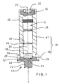
- a mounting device is presented, before mounting, such as the superposition of a metal screw 10, of a clamping end monobloc 12 also metallic, and an insulating sleeve 14 made of synthetic material enveloping the clamping end piece 12 and the head of the screw 10, these elements having an axis common geometric reference 20.
- the screw 10 consists of a threaded rod 22 according to a helix with an axis 20 and a cylindrical head 24 forming a hexagonal tightening relief hollow 26.
- the cylindrical periphery 28 of the head 24 is knurled.
- Clamping bit 12 comprises a cylindrical head 30 provided with a tightening relief 32 with identical hexagon socket to that of the screw head 24, an intermediate rod 34 and a hexagonal end 36 pressed into the hexagon relief 26 of the screw head 24.
- a rupture neck 38 in makes a notch, is formed on the intermediate rod 34 between its two ends and divides the end piece 12 into an upper part comprising the head 30 and a lower part having the hexagonal end 36.
- a radial groove 40 is formed between the neck 38 and the hexagonal end 36. Between the head 30 and the neck 38, a portion of the rod takes on a relief knurled 42.
- the insulating sleeve 14 is molded radially on the clamping end piece 12 and the head of the screw 24, leaving accessible the hexagon relief 32 of the head 30 of the mouthpiece.
- the sleeve forms a body 47 covering the end piece 12 and a skirt 48 which covers the screw head 24.
- the rod 22 of the screw and the shoulder 44 formed by the part bottom of the screw head 24 are not covered.
- a radial fracture notch 50 located just above the screw head 24 separates the body 47 from the skirt 48.
- the portions knurled knobs 28, 42 of the screw head and of the intermediate rod of the clamping end piece constitute fastening zones respectively between the sleeve 14 and the screw 10 on the one hand, and between the sleeve 14 and the upper part of the end piece 12 on the other hand.
- a inner rib 46 is formed during the molding of the sleeve 14 at the level of the groove 40.
- the one-piece mounting device is presented in the screwing, and a male hexagonal key inserted in the head 30 of the end piece is used to screw the device along axis 20.
- the screwing torque is almost entirely transmitted by the intermediate rod 34 at the screw head 24 and the sleeve 14 is almost not sought.
- the operator must still impose sufficient torque to break the intermediate rod 34 at the breaking zone 38. This pair of rupture is calibrated to correspond to the desired tightening torque for screw 10 in its application.
- the head 30 of the endpiece remains integral with the screw head 24, via the sleeve 14.
- This sub-assembly has a cylindrical insulating surface on the major part of its periphery, which avoids any risk of short circuit if this sub-assembly is forgotten.
- the device imposes a tightening torque on the screw precise corresponding to the breaking torque of the neck, because as long as the neck and the sleeve are not not broken, the device remains in one piece, and the size of the nozzle prohibits mounting operations which must follow the screwing of the screw.
- the torque limiter since the screw 10 does not offer a grip as long as it is integral with the end piece 12, so that it is guaranteed that the screw 10 is not tightened beyond the breaking torque.
- the break at the level of the notch 50 gives access to the relief to six hollow sides of the screw head, via an opening 52 released by the end hexagonal 36, which allows the disassembly of screw 10 if necessary.
- disassembly can be identical to the mounting tool because the mounting reliefs 26 of the head of screws and those 32 of the head of the end piece are identical.
- a mounting device consists of a screw 10, a clamping end piece 12, a rod coupling 60 and an insulating cap 62, arranged along the same axis geometric reference 20.
- the screw 10 is made up a threaded rod 22 and a head 24, this head forming a shoulder 44, a relief of tightening 26 with hexagon socket, and a knurling relief 28 on its cylindrical periphery.
- the metal endpiece 12 comprises a head 30 provided with a tightening relief 32 identical to that of the screw head, this head extending by a body 34 whose hexagonal end 36 is inserted into the hollow relief 26 of the screw head.
- the body 34 is provided with a neck radial rupture 38, and a groove 64 located near the screw head 24.
- the end piece 12 is tubular, which allows the insertion of the coupling rod 60, whose ends 62, 64 are pushed back to come to rest on chamfers 66, 68 made in the end piece.
- the cap 62 is secured to the body by a lip 70 penetrating into the groove 64.
- the cap 62 is also secured to the screw head 24 at the level of the knurled cylindrical part 28.
- the one-piece mounting device is presented in the screwing, and a male hexagonal key inserted in the head 30 of the end piece is used to screw the device.
- the tightening torque is fully transmitted to the screw head by through the body 34 of the end cap
- the cap 62 is not stressed.
- the screw 10 found blocked at the end of the race, it is necessary to exert a breaking torque on the head 30 of the endpiece to obtain a rupture of the endpiece at the level of the rupture neck 38.
- the head 30 of the endpiece remains integral in translation with the hexagonal end 36, by means of the coupling rod 60 which however allows movement of rotation of the head 30 of the nozzle relative to the hexagonal end 36.
- FIG. 3 a mounting device according to a third mode of realization of the invention.
- the device comprises a screw 10, a breakable end 12 and a coupling sleeve 14.
- the head 24 of the screw has a hexagonal male tightening relief 26.
- This relief 26 has grooves radial 80 in the corners.
- the end piece 12 is provided at one end with a head 30 having the same hexagonal shape 32 as the screw head and, at the other end, with a hexagon wrench hollow 36 into which the screw head is inserted.
- This key 36 is provided with at least one slot longitudinal 82 giving access to one of the angles of the screw head 24.
- the body of the bit consists of a rod 34 comprising a breakable neck 38, a coupling knurling 42 located between the neck 38 and the head 30 of the nozzle, and a groove 40 located between the neck 38 and the key 36.
- the coupling sleeve 14 is molded onto the end piece 12. It is integral with the end piece at the knurling 42 and the groove 40, and integral with the screw head 24 at level of the slot 82 and the corresponding groove 80.
- the one-piece mounting device is presented in the screwing, and a female hexagonal key is used to screw the device through the head 30 of the mouthpiece.
- the tightening torque is transmitted by the rod 34 to the screw head 24 and the sleeve 14 is not requested.
- the operator must still impose a torque sufficient to break the rod 34 at the neck 38.
- the two parts of the endpiece remain integral with each other via the sleeve 14.
- a weak torque exerted on the head 30 of the nozzle, transmitted to the sleeve 14 at the level of the zone knurled 42, is sufficient to cause the rupture of the sleeve at the level of the groove 80.
- the rupture zone 38 of the end piece can take any form allowing a rupture to a predetermined torque in torsion: neck, notch, groove, breaking point, etc.
- the body 47 of the sleeve may not cover the clamping head 30, which makes it possible, if necessary, to reduce the size of the device.
- the coupling between the screw head 24 and the breakable tip 12 can be done by any appropriate relief: slot, slots, cruciform, square or other imprint, male or female.
- the screw head 24 does not necessarily have a shoulder.
- the head of screw 24 is not necessarily of a radial size greater than that of the part threaded 22.
- the invention finds its interest when the tightening torque is important, in which case the use of metals for the end piece 12 and the screw 10 is particularly advantageous. However, the use of other materials is not excluded.
Landscapes
- Engineering & Computer Science (AREA)
- General Engineering & Computer Science (AREA)
- Mechanical Engineering (AREA)
- Details Of Spanners, Wrenches, And Screw Drivers And Accessories (AREA)
- Connection Of Plates (AREA)
- Bolts, Nuts, And Washers (AREA)
Abstract
Description
- une vis pourvue d'une tête de vis et d'une tige filetée définissant un axe géométrique de référence,
- un embout de serrage monobloc sécable comportant :
- une tête de serrage ayant un relief de serrage pour coopérer avec un outil de serrage,
- un relief d'accouplement pour coopérer avec la tête de vis, assurant dans une position d'engagement avec la tête de vis un accouplement en rotation autour de l'axe géométrique de référence entre l'embout de serrage et la tête de vis, et mobile vers une position de désengagement par translation par rapport à la tête de vis, suivant l'axe géométrique de référence,
- une zone de rupture, située entre la tête de serrage et le relief d'accouplement et reliant la tête de serrage au relief d'accouplement de telle manière que la tête de serrage et le relief d'accouplement sont solidaires en rotation autour de l'axe géométrique de référence, la zone de rupture étant dimensionnée pour se rompre lorsqu'elle est soumise à un couple dépassant un seuil prédéterminé de rupture,
- des premiers moyens d'accouplement pour solidariser en translation suivant l'axe géométrique de référence la tête de serrage et le relief d'accouplement lorsque la zone de rupture est rompue ;
- des deuxièmes moyens d'accouplement pour solidariser en translation suivant l'axe géométrique de référence la tête de vis au relief d'accouplement en position d'accouplement tant que la zone de rupture n'est pas rompue, les deuxièmes moyens d'accouplement pouvant passer dans un état de désolidarisation qui permet de faire passer le relief d'accouplement en position de désengagement, lorsque la zone de rupture est rompue et qu'est appliqué aux deuxièmes moyens d'accouplement une force ou un couple dépassant un seuil donné.
- une première portion solidaire en rotation de la tête de serrage,
- une deuxième portion solidaire en rotation de la tête de vis, et
- une troisième portion intermédiaire sécable solidarisant la première portion à la deuxième portion, la troisième portion étant dimensionnée pour ne pas se rompre tant que la zone de rupture n'est pas rompue et pour se rompre et faire ainsi passer les deuxièmes moyens d'accouplement dans l'état de désengagement, lorsque la zone de rupture est rompue et que la troisième portion est soumise à un couple dépassant un seuil prédéterminé de séparation inférieur au seuil prédéterminé de rupture.
- un appareillage électrique pourvu d'au moins une borne électrique de raccordement à vis,
- au moins un dispositif de montage par vissage selon la description précédente, pour fixer la borne de raccordement à un conducteur électrique.
- la figure 1 représente en coupe axiale un dispositif de montage suivant un premier mode de réalisation de l'invention;
- la figure 2 représente en coupe axiale un dispositif de montage suivant un deuxième mode de réalisation de l'invention;
- la figure 3 représente en coupe axiale un dispositif de montage suivant un troisième mode de réalisation de l'invention.
Claims (10)
- Dispositif de montage par vissage à limitation du couple de serrage, comportantcaractérisé en ce qu'il comporte en outre :une vis (10) pourvue d'une tête de vis (24) et d'une tige filetée (22) définissant un axe géométrique de référence (20),un embout de serrage monobloc sécable (12) comportant :une tête de serrage (30) ayant un relief de serrage (32) pour coopérer avec un outil de serrage,un relief d'accouplement (36) pour coopérer avec la tête de vis (24), assurant dans une position d'engagement avec la tête de vis (24) un accouplement en rotation autour de l'axe géométrique de référence (20) entre l'embout de serrage (12) et la tête de vis (10), et mobile vers une position de désengagement par translation par rapport à la tête de vis (24), suivant l'axe géométrique de référence (24),une zone de rupture (38), située entre la tête de serrage (30) et le relief d'accouplement (26) et reliant la tête de serrage (32) au relief d'accouplement (26) de telle manière que la tête de serrage (30) et le relief d'accouplement (26) sont solidaires en rotation autour de l'axe géométrique de référence, la zone de rupture (38) étant dimensionnée pour se rompre lorsqu'elle est soumise à un couple dépassant un seuil prédéterminé de rupture,des premiers moyens d'accouplement (40, 60) pour solidariser en translation suivant l'axe géométrique de référence la tête de serrage et le relief d'accouplement lorsque la zone de rupture est rompue ;des deuxièmes moyens d'accouplement (50) pour solidariser en translation suivant l'axe géométrique de référence la tête de vis (24) au relief d'accouplement (36) en position d'accouplement tant que la zone de rupture n'est pas rompue, les deuxièmes moyens d'accouplement pouvant passer dans un état de désolidarisation qui permet de faire passer le relief d'accouplement en position de désengagement, lorsque la zone de rupture est rompue et qu'est appliqué aux deuxièmes moyens d'accouplement une force ou un couple dépassant un seuil donné.
- Dispositif selon la revendication 1, caractérisé en ce que les deuxièmes moyens d'accouplement comportent :une première portion (47) solidaire en rotation de la tête de serrage,une deuxième portion (28) solidaire en rotation de la tête de vis, etune troisième portion intermédiaire sécable (50) solidarisant la première portion à la deuxième portion, la troisième portion étant dimensionnée pour ne pas se rompre tant que la zone de rupture n'est pas rompue et pour se rompre et faire ainsi passer les deuxièmes moyens d'accouplement dans l'état de désengagement, lorsque la zone de rupture (38) est rompue et que la troisième portion est soumise à un couple dépassant un seuil prédéterminé de séparation inférieur au seuil prédéterminé de rupture.
- Dispositif selon la revendication 2, caractérisé en ce que les deuxièmes moyens d'accouplement ont une rigidité en torsion suivant l'axe géométrique de référence entre la première portion et la deuxième portion, qui est inférieure celle de l'embout.
- Dispositif selon la revendication 3, caractérisé en ce que les premiers moyens d'accouplement et les deuxièmes moyens d'accouplement sont réalisés d'un seul bloc (14) en matière plastique isolante.
- Dispositif selon la revendication 4, caractérisé en ce que l'embout (12) est métallique.
- Dispositif selon la revendication 5, caractérisé en ce que le bloc (14) en matière plastique isolante enveloppe l'embout métallique en laissant un accès au relief de serrage.
- Dispositif selon l'une quelconque des revendications précédentes, caractérisé en ce que les deuxièmes moyens d'accouplement comportent une jupe en (48) matériau plastique isolant enveloppant au moins partiellement la tête de vis (24) et restant solidaire de la tête de vis dans l'état de désolidarisation.
- Dispositif selon l'une quelconque des revendications précédentes, caractérisé en ce que la tête de vis (24) comporte un relief de serrage (26) identique au relief de serrage (32) de l'embout, l'embout (12) étant conformé de telle manière que le relief de serrage (26) de la tête de vis est inaccessible tant que le relief d'accouplement (36) est en position d'engagement.
- Dispositif selon la revendication 8, caractérisé en ce que le relief de serrage (26) de la tête de vis et le relief de serrage (32) de l'embout sont en creux.
- Kit comportant :un appareillage électrique pourvu d'au moins une borne électrique de raccordement à vis,au moins un dispositif de montage par vissage selon l'une des revendications 1 à 9, pour fixer la borne de raccordement à un conducteur électrique.
Applications Claiming Priority (2)
| Application Number | Priority Date | Filing Date | Title |
|---|---|---|---|
| FR0206540 | 2002-05-29 | ||
| FR0206540A FR2840373B1 (fr) | 2002-05-29 | 2002-05-29 | Dispositif de montage secable a vis pour un appareillage electrique |
Publications (2)
| Publication Number | Publication Date |
|---|---|
| EP1367269A1 true EP1367269A1 (fr) | 2003-12-03 |
| EP1367269B1 EP1367269B1 (fr) | 2004-10-13 |
Family
ID=29415136
Family Applications (1)
| Application Number | Title | Priority Date | Filing Date |
|---|---|---|---|
| EP20030354038 Expired - Lifetime EP1367269B1 (fr) | 2002-05-29 | 2003-04-23 | Dispositif de montage sécable à vis pour un appareillage électrique |
Country Status (4)
| Country | Link |
|---|---|
| EP (1) | EP1367269B1 (fr) |
| DE (1) | DE60300091D1 (fr) |
| ES (1) | ES2229195T3 (fr) |
| FR (1) | FR2840373B1 (fr) |
Cited By (4)
| Publication number | Priority date | Publication date | Assignee | Title |
|---|---|---|---|---|
| FR2857067A1 (fr) * | 2003-07-02 | 2005-01-07 | Peugeot Citroen Automobiles Sa | Vis de serrage au couple |
| ITMI20082036A1 (it) * | 2008-11-17 | 2010-05-18 | Agliati S R L | Inserto limitatore di coppia |
| FR3065498A1 (fr) * | 2017-04-21 | 2018-10-26 | Upeca | Systeme de vis a tete secable et procede de fabrication d'un tel systeme |
| US10960546B2 (en) * | 2015-10-16 | 2021-03-30 | Abb Schweiz Ag | Shear pin for robot calibration |
Families Citing this family (2)
| Publication number | Priority date | Publication date | Assignee | Title |
|---|---|---|---|---|
| FR2881485B1 (fr) * | 2005-02-01 | 2007-03-02 | Schneider Electric Ind Sas | Dispositif de montage secable a vis pour un appareillage electrique |
| PL2079091T3 (pl) | 2008-01-10 | 2014-07-31 | Schneider Electric Ind Sas | Obudowa wyzwalacza elektronicznego dla wyłącznika samoczynnego, elektroniczne urządzenie rozłączające i sposób montażu |
Citations (5)
| Publication number | Priority date | Publication date | Assignee | Title |
|---|---|---|---|---|
| GB898026A (en) | 1958-12-29 | 1962-06-06 | Guest Keen & Nettlefolds Ltd | Improvements in screw-threaded bolts |
| GB2067699A (en) * | 1980-01-23 | 1981-07-30 | Ferranti Measurements Ltd | Tamper-proof fastening |
| FR2593572A1 (fr) | 1986-01-27 | 1987-07-31 | Verlant Beaurain | Vis a tete isolee, notamment pour applications electriques |
| JPH09144734A (ja) * | 1995-11-27 | 1997-06-03 | Maruemu Seisakusho:Kk | トルクリミット付きボルト |
| FR2791404A1 (fr) | 1999-03-26 | 2000-09-29 | Mecelec Ind | Vis a serrage calibre, son procede de fabrication et systeme de raccordement electrique incorporant une telle vis |
-
2002
- 2002-05-29 FR FR0206540A patent/FR2840373B1/fr not_active Expired - Fee Related
-
2003
- 2003-04-23 ES ES03354038T patent/ES2229195T3/es not_active Expired - Lifetime
- 2003-04-23 DE DE2003600091 patent/DE60300091D1/de not_active Expired - Lifetime
- 2003-04-23 EP EP20030354038 patent/EP1367269B1/fr not_active Expired - Lifetime
Patent Citations (5)
| Publication number | Priority date | Publication date | Assignee | Title |
|---|---|---|---|---|
| GB898026A (en) | 1958-12-29 | 1962-06-06 | Guest Keen & Nettlefolds Ltd | Improvements in screw-threaded bolts |
| GB2067699A (en) * | 1980-01-23 | 1981-07-30 | Ferranti Measurements Ltd | Tamper-proof fastening |
| FR2593572A1 (fr) | 1986-01-27 | 1987-07-31 | Verlant Beaurain | Vis a tete isolee, notamment pour applications electriques |
| JPH09144734A (ja) * | 1995-11-27 | 1997-06-03 | Maruemu Seisakusho:Kk | トルクリミット付きボルト |
| FR2791404A1 (fr) | 1999-03-26 | 2000-09-29 | Mecelec Ind | Vis a serrage calibre, son procede de fabrication et systeme de raccordement electrique incorporant une telle vis |
Non-Patent Citations (1)
| Title |
|---|
| PATENT ABSTRACTS OF JAPAN vol. 1997, no. 10 31 October 1997 (1997-10-31) * |
Cited By (4)
| Publication number | Priority date | Publication date | Assignee | Title |
|---|---|---|---|---|
| FR2857067A1 (fr) * | 2003-07-02 | 2005-01-07 | Peugeot Citroen Automobiles Sa | Vis de serrage au couple |
| ITMI20082036A1 (it) * | 2008-11-17 | 2010-05-18 | Agliati S R L | Inserto limitatore di coppia |
| US10960546B2 (en) * | 2015-10-16 | 2021-03-30 | Abb Schweiz Ag | Shear pin for robot calibration |
| FR3065498A1 (fr) * | 2017-04-21 | 2018-10-26 | Upeca | Systeme de vis a tete secable et procede de fabrication d'un tel systeme |
Also Published As
| Publication number | Publication date |
|---|---|
| ES2229195T3 (es) | 2005-04-16 |
| FR2840373A1 (fr) | 2003-12-05 |
| DE60300091D1 (de) | 2004-11-18 |
| EP1367269B1 (fr) | 2004-10-13 |
| FR2840373B1 (fr) | 2004-07-23 |
Similar Documents
| Publication | Publication Date | Title |
|---|---|---|
| EP2304848B1 (fr) | Borne electrique a vis, bornier comportant une telle borne electrique et appareil electrique comportant une tel bornier | |
| EP0269533A1 (fr) | Pince d'ancrage pour conducteur électrique isolé équipé d'un câble porteur également isolé | |
| EP2198483A2 (fr) | Cosse pour connexion electrique et son procede d'assemblage | |
| FR3058360B1 (fr) | Unite electronique de mesure de parametres de fonctionnement d'une roue de vehicule | |
| FR2977384A1 (fr) | Connecteur pour relier l'un a l'autre deux cables electriques | |
| EP1367269B1 (fr) | Dispositif de montage sécable à vis pour un appareillage électrique | |
| EP3225360A1 (fr) | Accessoire de serrage au bon couple, et appareil de protection électrique comportant au moins une borne raccordée au moyen d'un tel accessoire | |
| EP2375502B1 (fr) | Dispositif de serrage à tête sécable pour manchon de raccord électrique | |
| EP1198684B1 (fr) | Embout de protection pour une extremite de tube | |
| FR2663380A1 (fr) | Embout de vissage cassable et jetable a couple de vissage predetermine. | |
| EP0706442B1 (fr) | Outil de serrage, notamment tournevis | |
| EP1686272B1 (fr) | Dispositif de montage secable a vis pour un appareillage electrique | |
| EP0911915B1 (fr) | Borne de raccordement électrique et élément terminal de tube luminescent la comportant | |
| EP2518831B1 (fr) | Manchon de raccordement pour câbles électriques | |
| FR3051606A1 (fr) | Dispositif de connexion pour un troncon terminal de cable electrique | |
| EP2090818B1 (fr) | Bouchon pour corps de valve de remplissage d'un circuit de climatisation pour véhicule automobile | |
| FR2560100A3 (fr) | Embout de vissage pour vis ou ecrous a couple de serrage limite | |
| FR3065498B1 (fr) | Systeme de vis a tete secable et procede de fabrication d'un tel systeme | |
| EP3062407B1 (fr) | Manchon de raccord entre câbles conducteurs, procédé de fabrication et procédé de mise en oeuvre d'un tel manchon. | |
| EP0648945A2 (fr) | Dispositif de fixation par vissage | |
| FR3018873A1 (fr) | Vis autocassante utilisee pour les contacts des fils et cables electriques | |
| FR3097911A1 (fr) | Système de vis électriquement isolée et son procédé de fabrication | |
| EP0458237B1 (fr) | Connecteur de câble coaxial | |
| FR3083376A1 (fr) | Terminal de connexion electrique a ensemble de serrage | |
| FR2967931A1 (fr) | Appareil d'application de couple isolant |
Legal Events
| Date | Code | Title | Description |
|---|---|---|---|
| PUAI | Public reference made under article 153(3) epc to a published international application that has entered the european phase |
Free format text: ORIGINAL CODE: 0009012 |
|
| AK | Designated contracting states |
Kind code of ref document: A1 Designated state(s): AT BE BG CH CY CZ DE DK EE ES FI FR GB GR HU IE IT LI LU MC NL PT RO SE SI SK TR |
|
| AX | Request for extension of the european patent |
Extension state: AL LT LV MK |
|
| 17P | Request for examination filed |
Effective date: 20040116 |
|
| GRAP | Despatch of communication of intention to grant a patent |
Free format text: ORIGINAL CODE: EPIDOSNIGR1 |
|
| GRAS | Grant fee paid |
Free format text: ORIGINAL CODE: EPIDOSNIGR3 |
|
| AKX | Designation fees paid |
Designated state(s): BE DE ES GB IT SE |
|
| GRAA | (expected) grant |
Free format text: ORIGINAL CODE: 0009210 |
|
| AK | Designated contracting states |
Kind code of ref document: B1 Designated state(s): BE DE ES GB IT SE |
|
| PG25 | Lapsed in a contracting state [announced via postgrant information from national office to epo] |
Ref country code: GB Free format text: LAPSE BECAUSE OF FAILURE TO SUBMIT A TRANSLATION OF THE DESCRIPTION OR TO PAY THE FEE WITHIN THE PRESCRIBED TIME-LIMIT Effective date: 20041013 |
|
| REG | Reference to a national code |
Ref country code: GB Ref legal event code: FG4D Free format text: NOT ENGLISH |
|
| REG | Reference to a national code |
Ref country code: IE Ref legal event code: FG4D Free format text: FRENCH |
|
| REF | Corresponds to: |
Ref document number: 60300091 Country of ref document: DE Date of ref document: 20041118 Kind code of ref document: P |
|
| PG25 | Lapsed in a contracting state [announced via postgrant information from national office to epo] |
Ref country code: DE Free format text: LAPSE BECAUSE OF FAILURE TO SUBMIT A TRANSLATION OF THE DESCRIPTION OR TO PAY THE FEE WITHIN THE PRESCRIBED TIME-LIMIT Effective date: 20050114 |
|
| REG | Reference to a national code |
Ref country code: SE Ref legal event code: TRGR |
|
| REG | Reference to a national code |
Ref country code: ES Ref legal event code: FG2A Ref document number: 2229195 Country of ref document: ES Kind code of ref document: T3 |
|
| GBV | Gb: ep patent (uk) treated as always having been void in accordance with gb section 77(7)/1977 [no translation filed] |
Effective date: 20041013 |
|
| REG | Reference to a national code |
Ref country code: IE Ref legal event code: FD4D |
|
| PLBE | No opposition filed within time limit |
Free format text: ORIGINAL CODE: 0009261 |
|
| STAA | Information on the status of an ep patent application or granted ep patent |
Free format text: STATUS: NO OPPOSITION FILED WITHIN TIME LIMIT |
|
| 26N | No opposition filed |
Effective date: 20050714 |
|
| PGFP | Annual fee paid to national office [announced via postgrant information from national office to epo] |
Ref country code: BE Payment date: 20160314 Year of fee payment: 14 |
|
| REG | Reference to a national code |
Ref country code: BE Ref legal event code: MM Effective date: 20170430 |
|
| PG25 | Lapsed in a contracting state [announced via postgrant information from national office to epo] |
Ref country code: BE Free format text: LAPSE BECAUSE OF NON-PAYMENT OF DUE FEES Effective date: 20170430 |
|
| PGFP | Annual fee paid to national office [announced via postgrant information from national office to epo] |
Ref country code: ES Payment date: 20200504 Year of fee payment: 18 |
|
| PGFP | Annual fee paid to national office [announced via postgrant information from national office to epo] |
Ref country code: IT Payment date: 20200312 Year of fee payment: 18 Ref country code: SE Payment date: 20200415 Year of fee payment: 18 |
|
| REG | Reference to a national code |
Ref country code: SE Ref legal event code: EUG |
|
| PG25 | Lapsed in a contracting state [announced via postgrant information from national office to epo] |
Ref country code: SE Free format text: LAPSE BECAUSE OF NON-PAYMENT OF DUE FEES Effective date: 20210424 |
|
| REG | Reference to a national code |
Ref country code: ES Ref legal event code: FD2A Effective date: 20220701 |
|
| PG25 | Lapsed in a contracting state [announced via postgrant information from national office to epo] |
Ref country code: ES Free format text: LAPSE BECAUSE OF NON-PAYMENT OF DUE FEES Effective date: 20210424 |
|
| PG25 | Lapsed in a contracting state [announced via postgrant information from national office to epo] |
Ref country code: IT Free format text: LAPSE BECAUSE OF NON-PAYMENT OF DUE FEES Effective date: 20200423 |
|
| PG25 | Lapsed in a contracting state [announced via postgrant information from national office to epo] |
Ref country code: IT Free format text: LAPSE BECAUSE OF NON-PAYMENT OF DUE FEES Effective date: 20210423 |