EP1367227A2 - Pre-assemblied chain drive with mounting aid - Google Patents
Pre-assemblied chain drive with mounting aid Download PDFInfo
- Publication number
- EP1367227A2 EP1367227A2 EP02028623A EP02028623A EP1367227A2 EP 1367227 A2 EP1367227 A2 EP 1367227A2 EP 02028623 A EP02028623 A EP 02028623A EP 02028623 A EP02028623 A EP 02028623A EP 1367227 A2 EP1367227 A2 EP 1367227A2
- Authority
- EP
- European Patent Office
- Prior art keywords
- propellant
- unit
- assembled
- assembly aid
- drive
- Prior art date
- Legal status (The legal status is an assumption and is not a legal conclusion. Google has not performed a legal analysis and makes no representation as to the accuracy of the status listed.)
- Granted
Links
Images

Classifications
-
- F—MECHANICAL ENGINEERING; LIGHTING; HEATING; WEAPONS; BLASTING
- F16—ENGINEERING ELEMENTS AND UNITS; GENERAL MEASURES FOR PRODUCING AND MAINTAINING EFFECTIVE FUNCTIONING OF MACHINES OR INSTALLATIONS; THERMAL INSULATION IN GENERAL
- F16H—GEARING
- F16H7/00—Gearings for conveying rotary motion by endless flexible members
- F16H7/24—Equipment for mounting belts, ropes, or chains
-
- F—MECHANICAL ENGINEERING; LIGHTING; HEATING; WEAPONS; BLASTING
- F01—MACHINES OR ENGINES IN GENERAL; ENGINE PLANTS IN GENERAL; STEAM ENGINES
- F01L—CYCLICALLY OPERATING VALVES FOR MACHINES OR ENGINES
- F01L1/00—Valve-gear or valve arrangements, e.g. lift-valve gear
- F01L1/02—Valve drive
-
- F—MECHANICAL ENGINEERING; LIGHTING; HEATING; WEAPONS; BLASTING
- F01—MACHINES OR ENGINES IN GENERAL; ENGINE PLANTS IN GENERAL; STEAM ENGINES
- F01L—CYCLICALLY OPERATING VALVES FOR MACHINES OR ENGINES
- F01L1/00—Valve-gear or valve arrangements, e.g. lift-valve gear
- F01L1/02—Valve drive
- F01L1/022—Chain drive
-
- F—MECHANICAL ENGINEERING; LIGHTING; HEATING; WEAPONS; BLASTING
- F01—MACHINES OR ENGINES IN GENERAL; ENGINE PLANTS IN GENERAL; STEAM ENGINES
- F01L—CYCLICALLY OPERATING VALVES FOR MACHINES OR ENGINES
- F01L1/00—Valve-gear or valve arrangements, e.g. lift-valve gear
- F01L1/46—Component parts, details, or accessories, not provided for in preceding subgroups
-
- F—MECHANICAL ENGINEERING; LIGHTING; HEATING; WEAPONS; BLASTING
- F16—ENGINEERING ELEMENTS AND UNITS; GENERAL MEASURES FOR PRODUCING AND MAINTAINING EFFECTIVE FUNCTIONING OF MACHINES OR INSTALLATIONS; THERMAL INSULATION IN GENERAL
- F16H—GEARING
- F16H7/00—Gearings for conveying rotary motion by endless flexible members
- F16H7/08—Means for varying tension of belts, ropes, or chains
-
- F—MECHANICAL ENGINEERING; LIGHTING; HEATING; WEAPONS; BLASTING
- F01—MACHINES OR ENGINES IN GENERAL; ENGINE PLANTS IN GENERAL; STEAM ENGINES
- F01L—CYCLICALLY OPERATING VALVES FOR MACHINES OR ENGINES
- F01L1/00—Valve-gear or valve arrangements, e.g. lift-valve gear
- F01L1/02—Valve drive
- F01L2001/028—Pre-assembled timing arrangement, e.g. located in a cassette
-
- F—MECHANICAL ENGINEERING; LIGHTING; HEATING; WEAPONS; BLASTING
- F01—MACHINES OR ENGINES IN GENERAL; ENGINE PLANTS IN GENERAL; STEAM ENGINES
- F01L—CYCLICALLY OPERATING VALVES FOR MACHINES OR ENGINES
- F01L2303/00—Manufacturing of components used in valve arrangements
- F01L2303/01—Tools for producing, mounting or adjusting, e.g. some part of the distribution
-
- F—MECHANICAL ENGINEERING; LIGHTING; HEATING; WEAPONS; BLASTING
- F16—ENGINEERING ELEMENTS AND UNITS; GENERAL MEASURES FOR PRODUCING AND MAINTAINING EFFECTIVE FUNCTIONING OF MACHINES OR INSTALLATIONS; THERMAL INSULATION IN GENERAL
- F16H—GEARING
- F16H7/00—Gearings for conveying rotary motion by endless flexible members
- F16H7/08—Means for varying tension of belts, ropes, or chains
- F16H2007/0802—Actuators for final output members
- F16H2007/0804—Leaf springs
-
- F—MECHANICAL ENGINEERING; LIGHTING; HEATING; WEAPONS; BLASTING
- F16—ENGINEERING ELEMENTS AND UNITS; GENERAL MEASURES FOR PRODUCING AND MAINTAINING EFFECTIVE FUNCTIONING OF MACHINES OR INSTALLATIONS; THERMAL INSULATION IN GENERAL
- F16H—GEARING
- F16H7/00—Gearings for conveying rotary motion by endless flexible members
- F16H7/08—Means for varying tension of belts, ropes, or chains
- F16H2007/0842—Mounting or support of tensioner
-
- F—MECHANICAL ENGINEERING; LIGHTING; HEATING; WEAPONS; BLASTING
- F16—ENGINEERING ELEMENTS AND UNITS; GENERAL MEASURES FOR PRODUCING AND MAINTAINING EFFECTIVE FUNCTIONING OF MACHINES OR INSTALLATIONS; THERMAL INSULATION IN GENERAL
- F16H—GEARING
- F16H7/00—Gearings for conveying rotary motion by endless flexible members
- F16H7/08—Means for varying tension of belts, ropes, or chains
- F16H2007/0876—Control or adjustment of actuators
- F16H2007/0878—Disabling during transport
-
- F—MECHANICAL ENGINEERING; LIGHTING; HEATING; WEAPONS; BLASTING
- F16—ENGINEERING ELEMENTS AND UNITS; GENERAL MEASURES FOR PRODUCING AND MAINTAINING EFFECTIVE FUNCTIONING OF MACHINES OR INSTALLATIONS; THERMAL INSULATION IN GENERAL
- F16H—GEARING
- F16H7/00—Gearings for conveying rotary motion by endless flexible members
- F16H7/18—Means for guiding or supporting belts, ropes, or chains
Definitions
- the invention relates to a preassembled propellant unit with a support body, with at least a wheel holder, in each of which a drive center wheel can be received, and with an endless propellant that can be placed around the drive wheels.
- Pre-assembled propellant units are known in the prior art and are used, for example used for timing chains of internal combustion engines.
- 909 458 is a sprocket bracket and chain guide member for a timing chain is known in the arcuate grooves for the loose reception of the sprockets and the timing chain are provided.
- a groove for receiving a sprocket is by a detachable plate and the sprocket bracket and chain guide element educated.
- an embodiment shows the sprocket holder and chain guide element together with a pivoted, chain tensioning device tensioned by means of a compression spring.
- EP-A-0 848 139 is a pre-assembled traction drive unit with a one-piece Carrier known.
- the Traction device wheels with traction devices placed around for mounting in holding pockets and by means of a latching holding element configured in one piece with a holding device fixed.
- the aforementioned preassembled propellant units remain together with the supporting body after mounting on a drive unit, especially an engine block an internal combustion engine.
- a pre-assembly of the drive center wheels and the endless drive means become.
- Certain components of the propellant unit take over both during main assembly as well as in later use on the drive unit assigned functions. Other components and functions will appear later Operation completely in the background.
- the present invention has for its object a preassembled propellant unit to provide of the type mentioned in the various desired functional requirements is improved, in particular however, the assembly of the drive unit and the attachment of the drive wheels facilitated.
- this object is achieved by an exchangeable assembly aid, which is arranged in the area of the wheel holder instead of a drive center wheel.
- the assembly aid is designed to be exchangeable for a drive center wheel, so that no assembly aid is available when the drive unit unit attached to the drive unit is in operation. This leads to lower material consumption and lower costs. Due to the interchangeability of the assembly aid, the assembly aid can advantageously be reused. In order to be able to constantly return the assembly aid to the assembly circuit in a cost-saving manner, the assembly aid can therefore advantageously be designed to be repeatedly interchangeable with a drive wheel in a further development.
- the assembly aid fulfills additionally the task of creating a tension in the chain so that the pre-assembled Traction drive is easier to handle during installation and not apart falls.
- the assembly aid in the pre-assembled The propellant unit is preloaded elastically and a tension force in the endless propellant is built generating.
- the assembly aid can also be designed so that a drive unit already provided with at least one drive wheel Installation aid the at least one drive wheel via the endless drive in the pulling the wheel receptacle assigned to at least one drive center wheel and the pre-assembled propellant unit is designed to hold in position.
- This configuration also leads to a more stable cohesion of the pre-assembled propellant unit before installation. It is also conceivable that all sprockets through Assembly aids are replaced.
- a tensioning force in the endless drive means can be generated in particular by spreading the endless drive means in the area of the wheel holder by the assembly aid.
- This has the advantage that the spreading creates space for an unproblematic insertion of the drive center wheel, so that the assembly process is made even easier.
- the clear width of the assembly aid in the preassembled propellant unit can in particular be larger at least at one point than the diameter of the propellant wheel, which is installed instead of the assembly aid.
- the drive center wheel can be used particularly easily.
- the assembly aid can be U-shaped, for example. It can also have at least two legs which press elastically against the endless drive means. The endless propellant is spread apart by the at least two legs and the tensile stress is simultaneously generated in the endless propellant.
- the legs can also be supported elastically between the wheel receptacle and the endless drive means and can thus guide the endless drive means at a distance from the support body.
- the assembly aid can also be installed in the preassembled propellant unit in such a way that the legs are directed away from the supporting body, which facilitates the insertion of the propellant wheel into the wheel receptacle, for example, which is designed as a holding pocket.
- the assembly aid with at least one on the Handle acting be provided, when actuated the leg compressible to remove the assembly aid and the elastic preload the leg and thus the tension in the endless propellant can be reduced.
- the handle can for example be arranged on the legs themselves and in particular formed as a bent or folded end portion of the legs his. These designs are due from a manufacturing perspective their simple manufacture cheap. Another cheap embodiment provides that the handle is freely accessible from outside the drive unit is.
- the legs can by an im Substantially elastic, preferably curved section connected to each other his.
- This section can be supported, for example, on the support body, in particular in the holding pocket of the wheel holder, in the that of the assembly aid during operation assigned drive center wheel is held. On the other hand, this section can also be facing away from the support body and as a guide element for the endless propellant serve.
- the assembly aid can be designed in one piece as a single part, and for example made of spring steel, in particular a spring steel sheet.
- At least one tensioning device on the support body is arranged by the between two drive wheels or between the instead of these drive means provided mounting aids on a bias the endless propellant is applied.
- the arrangement of the clamping device on the support body offers the possibility to put together a compact propellant unit in advance, which can be assembled in a single assembly step. It can also Tensioning device for biasing the endless propellant can be used, in particular in cooperation with the assembly aid designed as a clamping device, which enables the drive center wheels to be secured in the assembled position becomes.
- An advantageous embodiment provides that the clamping device as one Is pivotally arranged on the support body arranged clamping rail.
- the tensioning rail is easy to assemble and various Leverage can be achieved through different clamping points.
- the tensioning device can be provided is biased by a spring device in which by different Design options for any application, different force profiles are realizable.
- the spring device can be designed as a leaf spring be, making a simple construction of the spring device with only a few Components is possible.
- the support body can advantageously consist of an aluminum die-cast part, whereby achieves a high strength with favorable vibration properties becomes.
- the support body can also from the point of view of cost optimization as sheet metal or aluminum sheet metal parts as well as a molded plastic part.
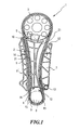
- Driving means unit 1 is provided as a control drive on an internal combustion engine.
- the preassembled propellant unit 1 comprises an essentially plate-shaped one Support body 2, a camshaft sprocket 3, one designed as a drive chain 4 Endless propellant, a guide rail 5 attached to the support body 2, a wheel holder 6 for the camshaft sprocket 3 as well as a mounting and locking for a tensioning rail 7. Furthermore, on the pre-assembled drive unit 1 instead of the crankshaft sprocket 8 (dashed line) an assembly aid 9 in the corresponding wheel holder 10 is provided.
- the wheel receptacles 6, 10 can be designed as holding pockets, which by connected to the support body 2 or formed by the support body 2, radially securing Side walls and axial locking elements are formed. To increase the strength are both on the guide rail 5 and on the tensioning rail 7 and on the support body 2 stiffening ribs 11 are formed.
- the tensioning rail 7 is between the tension of the drive chain 4 on the support body the camshaft sprocket 3 and the location of the crankshaft sprocket 8 attached outside of the area enclosed by the drive chain 4 and with an arcuate pressing surface 12.
- the end of the tensioning rail 7 facing the crankshaft sprocket 8 is on one connected to the support body 2 connected pin 13 rotatably.
- the guide rail 5 is on the drive chain 4 for wear protection facing side with interchangeable guide pads 14, the Grip the ends around the ends of the guide rail 5.
- the support body 2 is secure except for one Open side wall.
- the assembly aid 9 is supported on the side wall and tensions the drive chain 4 in a manner similar to that instead of the assembly aid 9 attached crankshaft sprocket would do.
- the camshaft sprocket 3 is pulled into the holding pocket 6 and secured in position.
- the assembly aid 9 clamping force generated by the clamping rail 7 and a counterforce generated so that the tensioning rail 7 due to the assembly aid 9th generated clamping force held in a stable, preloaded mounting position becomes.
- Fig. 2 shows the assembly aid of Fig. 1 in a plan view.
- the assembly aid 9 has an approximately U-shaped shape on, the two legs 15 connected by an arcuate section 16 are, which is supported on the side wall of the support body 2 of the propellant unit 1.
- the legs 15 each have an outwardly bent region 17 on, which is approximately at the point where the crankshaft sprocket 8 in the final assembly Propellant unit 1 comes to rest.
- the distance between the connecting section 16 and the ends of the legs 15 is selected so that when the preassembled propellant unit 1 is mounted on the Drive unit, for example an internal combustion engine, the chain essentially is guided as if the crankshaft sprocket 8 instead of the assembly aid 9 is attached.
- the assembly aid 9 is used in the final assembly Propellant unit 1 provided distance between the camshaft sprocket 3 and the crankshaft sprocket 8 are taken into account in the guidance of the endless drive means. In this way, the pre-assembled propellant unit can already in its Final assembly position may be attached to the drive unit, though not all Driving center wheels are mounted.
- the assembly aid 9 is also provided with a handle 18 when it is actuated the legs 15 are compressible.
- 2 is the Handle 18 as a bent area at the end of each leg 15 trained, which away from the drive chain 4 (see. Fig. 1) in the Mounting aid 9 spans the area. In this area is the handle 18 freely accessible for easy assembly and the assembly aid 9 easily and without complicated handles can be replaced by the crankshaft sprocket 8.
- Handle 18 can also separate components, such as handles or Handle sections, which are subsequently attached to the assembly aid 9.
- the assembly aid 9 is made of an elastic material, so that the legs 15 Keep their elasticity even when the handle is reused several times.
- the handle 9 can be made of spring steel.
- the height H the assembly aid 9 corresponds at least to the inner width B of the chain (cf. FIG. 3).
- FIG. 3 which shows the assembly aid in a view along the Arrow III of FIG. 2 shows that the handle 18 in particular on the Width B of the chain can protrude so that the crankshaft sprocket 8 is inserted can be while the assembly aid 9 is still installed.
- the assembly aid 9 projecting over the drive point 4 with the help of Handle 18 are removed from the propellant unit 1.
- the chain breaks then under the action of the tensioning rail 7 to the crankshaft sprocket 8.
- the removed one Assembly aid 9 can then be reused.
- the assembly aid 9 can also be installed immediately before the Crankshaft sprocket are removed in the chain.
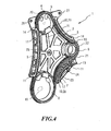
- FIG. 4 shows a preassembled propellant unit 1, the used to drive units of an internal combustion engine, not shown becomes.
- the components of the embodiment of FIG. 1st correspond, the same reference numerals as used in the embodiment of FIG. 1.
- the description of the exemplary embodiment 4 only points to the differences from the embodiment of FIG. 1.
- the different elements and forms of the embodiments of the 1 and 4 can be combined with one another as desired.
- the pre-assembled propellant unit 1 with receptacles 10 provided for a total of three sprockets 8, 19, 20.
- the sprockets 19 and 20 drive units of the internal combustion engine and are driven by the drive chain 4 driven by the crankshaft sprocket 8.
- the preassembled propellant unit 1 of FIG. 4 also has two external, arcuate ones Guide rails 5 on the support body 2.
- the guide rails 5 are between the sprockets 19 and 20 and between the sprocket 20 and the Crankshaft sprocket 8 arranged.
- To increase the strength of the guide rails are both on the outer sides and on those formed by the support body radially securing side walls 21 wedge-shaped stiffening elements (no Reference numerals) formed.
- the support body 2 is by striving along the the drive chain 4 and the sprockets 8, 19, 20 limited inner surface as well stiffened by star-shaped struts crossing this inner surface.
- a tensioning rail 7 with an arcuate pressure surface 12 is attached to the support body 2 between the crankshaft sprocket 8 and the sprocket 4 outside the drive chain 4.
- the end of the tensioning rail 7 directed towards the crankshaft sprocket 8 is rotatably mounted on a pin 13 connected to the support body 2, as in the embodiment of FIG. 1.
- an outer side wall is formed between the guide rail 5 between the sprocket 20 and the crankshaft sprocket 8 and the pin 13, which encloses the outer circumference of the crankshaft sprocket 3, and an outer side is provided with wedge-shaped stiffening elements.
- the tensioning force required for tensioning the drive chain 6 is applied by a leaf spring 23 which acts on the outside of the tensioning rail 7 facing away from the pressing surface 12.
- the leaf spring 23 can be tensioned with an adapter sleeve 24, the adapter sleeve 24 being supported on the firmly clamped outer part of the two-part leaf spring 23.
- a bore 25 and two further bores 26 and 27 are provided on the side of the chain wheel 20 in the center of the support body 2.
- the support body 2 is open in the area of the sprockets 19 and 20.
- an assembly aid 9 according to the invention is used instead of the respectively assigned sprocket 19 and 20.
- the connecting section 16 serves, for example, in the case of the assembly aid 9 assigned to the chain wheel 19 as a guide element for the drive chain 4, while the assembly aid 9 is supported on the support body 2 in the region of the end sections of the legs 15.
- the assembly aid 9 assigned to the sprocket 20, on the other hand, is shown installed in the assembly position as in the embodiment of FIG. 1.
- the drive chain 4 is guided approximately by the assembly aid as if the chain wheels 19, 20 are inserted.
- the assembly aids 9 pretension the chain 4 on the wheel receptacles 10 in such a way that the chain wheels 19, 20 can be inserted into the preassembled drive means unit 1 without great effort.
- the assembly aids 9 are elastically deformed by the interaction with the clamping force generated by the clamping rail 7.
- the clear width of the space spanned by the assembly aids 9 corresponds at least in sections at least the diameter of the assigned Sprocket 19, 20.
- the assembly aids 9 shortly after Hooking the sprockets 19, 20 removed and then reused.
Abstract
Description
Die Erfindung betrifft eine vormontierte Triebmitteleinheit mit einem Tragkörper, mit wenigstens einer Radaufnahme, in der jeweils ein Triebmittelrad aufnehmbar ist, und mit einem um die Triebmittelräder legbaren Endlostriebmittel.The invention relates to a preassembled propellant unit with a support body, with at least a wheel holder, in each of which a drive center wheel can be received, and with an endless propellant that can be placed around the drive wheels.
Vormontierte Triebmitteleinheiten sind im Stand der Technik bekannt und werden beispielsweise für Steuerketten von Brennkraftmaschinen verwendet. Aus der DE-OS 3 909 458 ist beispielsweise ein Kettenradhalterungs- und Kettenführungselement für eine Steuerkette bekannt, bei dem bogenförmige Nuten zur losen Aufnahme der Kettenräder und der Steuerkette vorgesehen sind. Eine Nut zur Aufnahme eines Kettenrades wird dabei durch eine lösbare Platte und das Kettenradhalterungs- und Kettenführungselement gebildet. Des Weiteren zeigt eine Ausführungsform das Kettenradhalterungs- und Kettenführungselement zusammen mit einer schwenkbar gelagerten, mittels einer Druckfeder gespannten Kettenspanneinrichtung.Pre-assembled propellant units are known in the prior art and are used, for example used for timing chains of internal combustion engines. From DE-OS 3 For example, 909 458 is a sprocket bracket and chain guide member for a timing chain is known in the arcuate grooves for the loose reception of the sprockets and the timing chain are provided. A groove for receiving a sprocket is by a detachable plate and the sprocket bracket and chain guide element educated. Furthermore, an embodiment shows the sprocket holder and chain guide element together with a pivoted, chain tensioning device tensioned by means of a compression spring.
Eine weitere vormontierte Triebmitteleinheit ist in der US-A-4 879 977 beschrieben. Bei dieser Vorrichtung werden zwei Zahnräder von einer entsprechend ausgeformten Führungsplatte in Position gehalten. Damit die Zahnräder in entsprechenden Aussparungen in dieser Führungsplatte angeordnet werden können, darf die Kette noch nicht geschlossen sein. Die Kette wird nach dem Einlegen der Zahnräder in die entsprechenden Aussparungen um die Zahnräder herumgelegt und verschlossen.Another pre-assembled propellant unit is described in US-A-4,879,977. In this device, two gears are shaped by one Guide plate held in place. So that the gears in appropriate recesses the chain can still be arranged in this guide plate not be closed. The chain is inserted into the corresponding after the gears Cutouts around the gears and closed.
Andere Möglichkeiten bestehen beispielsweise darin, den Tragkörper mehrteilig auszubilden, wie bei den Vorrichtungen der US-A-4 869 709 oder der EP-A-0 280 365, so dass die Triebmittelräder auch mit herumgelegtem Endlostriebmittel angeordnet werden können.Other options are, for example, the support body in several parts as in the devices of US-A-4 869 709 or EP-A-0 280 365, so that the drive wheels also with the endless drive lying around can be arranged.
Aus der EP-A-0 848 139 ist eine vormontierte Zugmitteltriebeinheit mit einem einteiligen Tragkörper bekannt. Bei dieser vormontierten Zugmitteltriebeinheit werden die Zugmittelräder mit herumgelegtem Zugmittel für die Montage in Haltetaschen positioniert und durch ein einteilig mit einer Haltevorrichtung ausgestaltetes Rasthalteelement fixiert. From EP-A-0 848 139 is a pre-assembled traction drive unit with a one-piece Carrier known. With this pre-assembled traction drive unit, the Traction device wheels with traction devices placed around for mounting in holding pockets and by means of a latching holding element configured in one piece with a holding device fixed.
Die vorgenannten vormontierten Triebmitteleinheiten verbleiben mitsamt des Tragkörpers nach der Montage an einer Antriebseinheit, insbesondere einem Motorblock einer Brennkraftmaschine. Hauptsächlich soll durch die Ausgestaltungen der Triebmitteleinheit eine Vormontage der Triebmittelräder und des Endlostriebmittels ermöglicht werden. Bestimmte Bauelemente der Triebmitteleinheit übernehmen dabei sowohl während der Hauptmontage als auch im späteren Einsatz an der Antriebseinheit zugewiesene Funktionen. Andere Bauelemente und Funktionen treten im späteren Betrieb vollständig in den Hintergrund. Die verschiedenen Aufgaben aus der Montage und dem späteren Einsatz führen - insbesondere im Hinblick auf die Verwendung der vormontierten Triebmitteleinheit im Bereich der Automobilindustrie, die dort vorhandenen hohen Stückzahlen sowie die fortschreitende Automatisierung - zu einem ständigen Verbesserungsbedarf und einer notwendigen Anpassung an gestiegene Anforderungen.The aforementioned preassembled propellant units remain together with the supporting body after mounting on a drive unit, especially an engine block an internal combustion engine. Mainly due to the designs of the propellant unit a pre-assembly of the drive center wheels and the endless drive means become. Certain components of the propellant unit take over both during main assembly as well as in later use on the drive unit assigned functions. Other components and functions will appear later Operation completely in the background. The different tasks from assembly and later use - especially with regard to use the pre-assembled propellant unit in the automotive industry, the existing ones high quantities as well as the increasing automation - all in one constant need for improvement and a necessary adaptation to increased Conditions.
Der vorliegenden Erfindung liegt die Aufgabe zugrunde, eine vormontierte Triebmitteleinheit der eingangs genannten Art bereitzustellen, die hinsichtlich der verschiedenen gewünschten funktionalen Anforderungen verbessert ausgeführt ist, insbesondere jedoch die Montage der Triebmitteleinheit und das Anbringen der Triebmittelräder erleichtert.The present invention has for its object a preassembled propellant unit to provide of the type mentioned in the various desired functional requirements is improved, in particular however, the assembly of the drive unit and the attachment of the drive wheels facilitated.
Diese Aufgabe wird erfindungsgemäß durch eine austauschbare Montagehilfe gelöst, die im Bereich der Radaufnahme anstelle eines Triebmittelrades angeordnet ist.According to the invention, this object is achieved by an exchangeable assembly aid, which is arranged in the area of the wheel holder instead of a drive center wheel.
Diese Lösung ist einfach und erleichtert das Einfädeln eines oder mehrerer
Triebmittelräder in das Endlostriebmittel. Dabei sind erfindungsgemäß eines oder
mehrere der Triebmittelräder durch die Montagehilfe ersetzt. Da die Montagehilfe
anstelle eines Triebmittelrades bei der vormontierten Triebmitteleinheit vorgesehen
ist, wird der gesamte vormontierte Trieb durch die Montagehilfe in Position gehalten,
obwohl eines oder mehrere der Triebmittelräder der vormontierten Triebmitteleinheit
fehlen.
Insbesondere kann dabei gemäß einer weiteren vorteilhaften Ausgestaltung vorgesehen
sein, dass die Montagehilfe gegen ein Triebmittelrad austauschbar ausgestaltet
ist, so dass beim Betrieb der an der Antriebseinheit angebrachten Triebmitteleinheit
keine Montagehilfe mehr vorhanden ist. Dies führt zu einem geringerem Materialverbrauch
und zu geringeren Kosten. Durch die Austauschbarkeit der Montagehilfe
kann vorteilhaft die Montagehilfe wiederverwendet werden. Um die Montagehilfe kostensparend
ständig in den Montagekreislauf zurückführen zu können, kann deshalb
vorteilhaft in einer Weiterbildung die Montagehilfe wiederholt gegen ein Triebmittelrad
austauschbar ausgestaltet sein.This solution is simple and makes it easier to thread one or more drive wheels into the endless drive. According to the invention, one or more of the drive center wheels are replaced by the assembly aid. Since the assembly aid is provided instead of a drive wheel in the preassembled drive unit, the entire preassembled drive is held in position by the assembly aid, although one or more of the drive wheels of the preassembled drive unit are missing.
In particular, it can be provided according to a further advantageous embodiment that the assembly aid is designed to be exchangeable for a drive center wheel, so that no assembly aid is available when the drive unit unit attached to the drive unit is in operation. This leads to lower material consumption and lower costs. Due to the interchangeability of the assembly aid, the assembly aid can advantageously be reused. In order to be able to constantly return the assembly aid to the assembly circuit in a cost-saving manner, the assembly aid can therefore advantageously be designed to be repeatedly interchangeable with a drive wheel in a further development.
In einer anderen vorteilhaften Weiterbildung der Erfindung erfüllt die Montagehilfe zusätzlich die Aufgabe, eine Spannung in der Kette zu erzeugen, so dass der vormontierte Zugmitteltrieb beim Einbau leichter handzuhaben ist und nicht auseinander fällt. Hierzu kann vorgesehen sein, dass die Montagehilfe in der vormontierten Triebmitteleinheit elastisch vorgespannt und eine Spannkraft im Endlostriebmittel erzeugend eingebaut ist.In another advantageous development of the invention, the assembly aid fulfills additionally the task of creating a tension in the chain so that the pre-assembled Traction drive is easier to handle during installation and not apart falls. For this purpose it can be provided that the assembly aid in the pre-assembled The propellant unit is preloaded elastically and a tension force in the endless propellant is built generating.
In diesem Zusammenhang kann die Montagehilfe auch so ausgestaltet sein, dass bei einer mit bereits wenigstens einem Triebmittelrad versehenen Triebmitteleinheit die Montagehilfe das wenigstens eine Triebmittelrad über das Endlostriebmittel in die dem wenigstens einem Triebmittelrad zugeordnete Radaufnahme ziehend und die vormontierte Triebmitteleinheit in Position haltend ausgestaltet ist. Diese Ausgestaltung führt ebenfalls zu einem stabileren Zusammenhalt der vormontierten Triebmitteleinheit vor dem Einbau. Es ist auch denkbar, dass sämtliche Kettenräder durch Montagehilfen ersetzt sind.In this context, the assembly aid can also be designed so that a drive unit already provided with at least one drive wheel Installation aid the at least one drive wheel via the endless drive in the pulling the wheel receptacle assigned to at least one drive center wheel and the pre-assembled propellant unit is designed to hold in position. This configuration also leads to a more stable cohesion of the pre-assembled propellant unit before installation. It is also conceivable that all sprockets through Assembly aids are replaced.
Eine Spannkraft im Endlostriebmittel kann insbesondere dadurch erzeugt werden,
dass das Endlostriebmittel im Bereich der Radaufnahme durch die Montagehilfe aufgespreizt
wird. Dies hat den Vorteil, dass durch die Aufspreizung gleichzeitig Platz
für ein unproblematisches Einsetzen des Triebmittelrades geschaffen wird, so dass
der Montagevorgang nochmals erleichtert wird. Hierzu kann insbesondere die lichte
Weite der Montagehilfe in der vormontierten Triebmitteleinheit an wenigstens einer
Stelle größer sein als der Durchmesser des Triebmittelrades, das anstelle der Montagehilfe
montiert wird. Bei dieser Maßnahme kann das Triebmittelrad besonders
einfach eingesetzt werden. Die Montagehilfe kann beispielsweise U-förmig ausgestaltet
sein. Sie kann auch wenigstens zwei gegen das Endlostriebmittel elastisch
drückende Schenkel aufweisen. Durch die wenigstens zwei Schenkel wird das Endlostriebmittel
aufgespreizt und gleichzeitig die Zugspannung im Endlostriebmittel erzeugt.
Die Schenkel können sich außerdem zwischen der Radaufnahme und dem
Endlostriebmittel elastisch abstützen und das Endlostriebmittel so vom Tragkörper
beabstandet führen.
Die Montagehilfe kann ferner dazu so in die vormontierte Triebmitteleinheit eingebaut
sein, dass die Schenkel vom Tragkörper weggerichtet sind, was das Einsetzen des
Triebmittelrades in die beispielsweise als Haltetasche ausgebildete Radaufnahme
erleichtert.A tensioning force in the endless drive means can be generated in particular by spreading the endless drive means in the area of the wheel holder by the assembly aid. This has the advantage that the spreading creates space for an unproblematic insertion of the drive center wheel, so that the assembly process is made even easier. For this purpose, the clear width of the assembly aid in the preassembled propellant unit can in particular be larger at least at one point than the diameter of the propellant wheel, which is installed instead of the assembly aid. With this measure, the drive center wheel can be used particularly easily. The assembly aid can be U-shaped, for example. It can also have at least two legs which press elastically against the endless drive means. The endless propellant is spread apart by the at least two legs and the tensile stress is simultaneously generated in the endless propellant. The legs can also be supported elastically between the wheel receptacle and the endless drive means and can thus guide the endless drive means at a distance from the support body.
For this purpose, the assembly aid can also be installed in the preassembled propellant unit in such a way that the legs are directed away from the supporting body, which facilitates the insertion of the propellant wheel into the wheel receptacle, for example, which is designed as a holding pocket.
Um die Montagehilfe beim Austausch gegen das der Montagehilfe zugeordnete Triebmittelrad zu erleichtern, kann die Montagehilfe mit wenigstens einer auf die Schenkel einwirkenden Handhabe versehen sein, bei deren Betätigung die Schenkel zum Ausbau der Montagehilfe zusammendrückbar und die elastische Vorspannung der Schenkel und damit die Spannkraft im Endlostriebmittel verringerbar sind.In order to replace the assembly aid with the one assigned to the assembly aid To facilitate drive center wheel, the assembly aid with at least one on the Handle acting be provided, when actuated the leg compressible to remove the assembly aid and the elastic preload the leg and thus the tension in the endless propellant can be reduced.
Die Handhabe kann beispielsweise an den Schenkeln selbst angeordnet und insbesondere als ein abgebogener oder abgekanteter Endabschnitt der Schenkel ausgebildet sein. Diese Ausgestaltungen sind aus fertigungstechnischer Sicht aufgrund ihrer einfachen Herstellung günstig. Eine weitere günstige Ausführungsform sieht vor, dass die Handhabe von außerhalb der Triebmitteleinheit frei zugänglich angeordnet ist.The handle can for example be arranged on the legs themselves and in particular formed as a bent or folded end portion of the legs his. These designs are due from a manufacturing perspective their simple manufacture cheap. Another cheap embodiment provides that the handle is freely accessible from outside the drive unit is.
In einer weiteren vorteilhaften Ausgestaltung können die Schenkel durch einen im Wesentlichen elastischen, vorzugsweise gebogenen Abschnitt miteinander verbunden sein. Dieser Abschnitt kann sich beispielweise am Tragkörper abstützen, insbesondere in der Haltetasche der Radaufnahme, in der im Betrieb das der Montagehilfe zugeordnete Triebmittelrad gehalten ist. Andererseits kann dieser Abschnitt auch vom Tragkörper weggewandt sein und als Führungselement für das Endlostriebmittel dienen.In a further advantageous embodiment, the legs can by an im Substantially elastic, preferably curved section connected to each other his. This section can be supported, for example, on the support body, in particular in the holding pocket of the wheel holder, in the that of the assembly aid during operation assigned drive center wheel is held. On the other hand, this section can also be facing away from the support body and as a guide element for the endless propellant serve.
Die Montagehilfe kann einstückig als ein einziges Teil ausgestaltet sein, und beispielsweise aus Federstahl, insbesondere einem Federstahlblech, gefertigt sein.The assembly aid can be designed in one piece as a single part, and for example made of spring steel, in particular a spring steel sheet.
Ferner kann vorgesehen sein, dass mindestens eine Spanneinrichtung am Tragkörper angeordnet ist, durch die zwischen zwei Triebmittelrädern bzw. zwischen den anstelle dieser Triebmittelräder vorgesehenen Montagehilfen eine Vorspannung auf das Endlostriebmittel aufgebracht ist. Die Anordnung der Spanneinrichtung am Tragkörper bietet die Möglichkeit, eine kompakte Triebmitteleinheit vorab zusammenzustellen, die in einem einzigen Montageschritt montiert werden kann. Auch kann die Spanneinrichtung zur Vorspannung des Endlostriebmittels genutzt werden, insbesondere im Zusammenwirkung mit der als Spannmittel ausgestalteten Montagehilfe, wodurch eine Sicherung der Triebmittelräder in der montierten Stellung ermöglicht wird.Furthermore, it can be provided that at least one tensioning device on the support body is arranged by the between two drive wheels or between the instead of these drive means provided mounting aids on a bias the endless propellant is applied. The arrangement of the clamping device on the support body offers the possibility to put together a compact propellant unit in advance, which can be assembled in a single assembly step. It can also Tensioning device for biasing the endless propellant can be used, in particular in cooperation with the assembly aid designed as a clamping device, which enables the drive center wheels to be secured in the assembled position becomes.
Eine vorteilhafte Ausgestaltung sieht dabei vor, dass die Spanneinrichtung als eine schwenkbar am Tragkörper angeordnete Spannschiene ausgestaltet ist. Durch die schwenkbare Anordnung ist die Spannschiene einfach montierbar und verschiedene Hebelkräfte sind durch unterschiedliche Spannansatzpunkte erreichbar.An advantageous embodiment provides that the clamping device as one Is pivotally arranged on the support body arranged clamping rail. Through the swiveling arrangement, the tensioning rail is easy to assemble and various Leverage can be achieved through different clamping points.
Gemäß einer weiteren günstigen Variante kann vorgesehen sein, dass die Spanneinrichtung durch eine Federeinrichtung vorgespannt ist, bei der durch unterschiedliche Ausgestaltungsmöglichkeiten für beliebige Einsatzzwecke unterschiedliche Kraftverläufe verwirklichbar sind. Die Federeinrichtung kann dabei als eine Blattfeder ausgestaltet sein, wodurch eine einfache Konstruktion der Federeinrichtung mit nur wenigen Komponenten möglich ist.According to a further advantageous variant, the tensioning device can be provided is biased by a spring device in which by different Design options for any application, different force profiles are realizable. The spring device can be designed as a leaf spring be, making a simple construction of the spring device with only a few Components is possible.
Der Tragkörper kann vorteilhaft aus einem Aluminium-Druckgussteil bestehen, wodurch eine hohe Festigkeit bei gleichzeitig günstigen Schwingungseigenschaften erreicht wird. Neben dieser bevorzugten Ausgestaltung kann der Tragkörper allerdings auch unter Kostenoptimierungsgesichtspunkten als Blech oder Aluminiumblechbiegeteil sowie als Kunststoffformteil realisiert werden.The support body can advantageously consist of an aluminum die-cast part, whereby achieves a high strength with favorable vibration properties becomes. In addition to this preferred embodiment, the support body can also from the point of view of cost optimization as sheet metal or aluminum sheet metal parts as well as a molded plastic part.
Im Folgenden werden Ausführungsbeispiele der Erfindung mit Bezug auf die Zeichnungen beispielhaft näher erläutert.Exemplary embodiments of the invention are described below with reference to FIG Drawings explained in more detail by way of example.
Es zeigen:
- Fig. 1
- eine Draufsicht auf eine erfindungsgemäße vormontierte Triebmitteleinheit mit einer Montagehilfe;
- Fig. 2
- die Montagehilfe der Fig. 1 in einer Draufsicht;
- Fig. 3
- eine Seitenansicht der Montagehilfe der Fig. 2;
- Fig. 4
- ein zweites Ausführungsbeispiel einer erfindungsgemäßen vormontierten Triebmitteleinheit mit zwei Montagehilfen.
- Fig. 1
- a plan view of a preassembled propellant unit according to the invention with an assembly aid;
- Fig. 2
- the assembly aid of Figure 1 in a plan view.
- Fig. 3
- a side view of the assembly aid of Fig. 2;
- Fig. 4
- a second embodiment of a pre-assembled propellant unit according to the invention with two assembly aids.
Das in Fig. 1 dargestellte Ausführungsbeispiel einer erfindungsgemäßen vormontierten
Triebmitteleinheit 1 ist als Steuertrieb an einer Brennkraftmaschine vorgesehen.The embodiment shown in Fig. 1 of a pre-assembled according to the invention
Driving means
Die vormontierte Triebmitteleinheit 1 umfasst einen im Wesentlichen plattenförmigen
Tragkörper 2, ein Nockenwellenkettenrad 3, ein als Antriebskette 4 ausgebildetes
Endlostriebmittel, eine am Tragkörper 2 befestigte Führungsschiene 5, eine Radaufnahme
6 für das Nockenwellenkettenrad 3 sowie eine Aufnahme und Verrasterung
für eine Spannschiene 7. Des Weiteren ist an der vormontierten Triebmitteleinheit 1
anstelle des Kurbelwellenkettenrades 8 (gestrichelte Linie) eine Montagehilfe 9 in der
entsprechenden Radaufnahme 10 vorgesehen.The
Die Radaufnahmen 6, 10 können als Haltetaschen ausgebildet sein, die durch mit
dem Tragkörper 2 verbundene oder vom Tragkörper 2 ausgebildete, radial sichernde
Seitenwände sowie durch axiale Sicherungselemente gebildet sind. Zur Erhöhung
der Festigkeit sind sowohl an der Führungsschiene 5, als auch an der Spannschiene
7 sowie am Tragkörper 2 Versteifungsrippen 11 ausgebildet.The
Die Spannschiene 7 ist zur Spannung der Antriebskette 4 auf dem Tragkörper zwischen
dem Nockenwellenkettenrad 3 und der Stelle des Kurbelwellenkettenrades 8
außerhalb des von der Antriebskette 4 umschlossenen Bereichs angebracht und mit
einer bogenförmigen Andrückfläche 12 versehen.The
Das zum Kurbelwellenkettenrad 8 gerichtete Ende der Spannschiene 7 ist auf einem
mit dem Tragkörper 2 verbundenen Stift 13 drehbar gelagert. The end of the
Die Führungsschiene 5 ist zum Verschleißschutz auf der der Antriebskette 4
zugewandten Seite mit auswechselbaren Führungsbelägen 14 versehen, deren
Enden um die Enden der Führungsschiene 5 herumgreifen.The
Im Bereich des Kurbelwellenkettenrades 8 ist der Tragkörper 2 bis auf eine sichernde
Seitenwand offen gestaltet. Die Montagehilfe 9 stützt sich an der Seitenwand ab und
spannt die Antriebskette 4 so auf, wie dies in etwa das anstelle der Montagehilfe 9
angebrachte Kurbelwellenkettenrad täte. Durch die von der Montagehilfe 9 ausgeübte
Spannkraft wird demnach das Nockenwellenkettenrad 3 in die Haltetasche 6 gezogen
und in seiner Position gesichert. Außerdem wird durch die Montagehilfe 9 die
von der Spannschiene 7 erzeugte Spannkraft aufgenommen und eine Gegenkraft
erzeugt, so dass auch die Spannschiene 7 aufgrund der durch die Montagehilfe 9
erzeugten Spannkraft in einer stabilen, vorgespannten Montageposition gehalten
wird.In the area of the
Wie in Fig. 1 zu erkennen ist, ist wenigstens eine lichte Weite der Montagehilfe 9 etwa
so groß, vorzugsweise jedoch größer, als der Durchmesser des Kurbelwellenkettenrades,
so dass das Kurbelwellenkettenrad 8 leicht montiert werden kann.As can be seen in FIG. 1, there is at least a clear width of the
Fig. 2 zeigt die Montagehilfe der Fig. 1 in einer Draufsicht.Fig. 2 shows the assembly aid of Fig. 1 in a plan view.
Wie in Fig. 2 zu erkennen ist, weist die Montagehilfe 9 eine in etwa U-förmige Form
auf, wobei die beiden Schenkel 15 durch einen bogenförmigen Abschnitt 16 verbunden
sind, der sich an der Seitenwand des Tragkörpers 2 der Triebmitteleinheit 1 abstützt.
Die Schenkel 15 weisen jeweils einen nach außen aufgebogenen Bereich 17
auf, der in etwa an der Stelle liegt, an der das Kurbelwellenkettenrad 8 in der endmontierten
Triebmitteleinheit 1 zu liegen kommt.As can be seen in FIG. 2, the
Der Abstand zwischen dem Verbindungsabschnitt 16 und den Enden der Schenkel
15 ist so gewählt, dass bei der Montage der vormontierten Triebmitteleinheit 1 an der
Antriebseinheit, beispielsweise einem Verbrennungskraftmotor, die Kette im Wesentlichen
so geführt wird, als ob das Kurbelwellenkettenrad 8 anstelle der Montagehilfe
9 angebracht ist. Insbesondere wird durch die Montagehilfe 9 der in der endmontierten
Triebmitteleinheit 1 vorgesehene Abstand zwischen dem Nockenwellenkettenrad
3 und dem Kurbelwellenkettenrad 8 in der Führung des Endlostriebmittels berücksichtigt.
Auf diese Weise kann die vormontierte Triebmitteleinheit bereits in ihrer
Endmontage-Stellung an der Antriebseinheit angebracht werden, obwohl nicht alle
Triebmittelräder montiert sind.The distance between the connecting
Die Montagehilfe 9 ist ferner mit einer Handhabe 18 versehen, bei deren Betätigung
die Schenkel 15 zusammendrückbar sind. Beim Ausführungsbeispiel der Fig. 2 ist die
Handhabe 18 als ein umgebogener Bereich am Ende eines jeden Schenkels 15
ausgebildet, der sich von der Antriebskette 4 weg (vgl. Fig. 1) in den von der
Montagehilfe 9 aufgespannten Bereich erstreckt. In diesem Bereich ist die Handhabe
18 für eine leichte Montage frei zugänglich und die Montagehilfe 9 einfach und ohne
komplizierte Handgriffe durch das Kurbelwellenkettenrad 8 austauschbar. Als
Handhabe 18 können auch separate Bauelemente, beispielsweise Griffe oder
Griffabschnitte, dienen, die nachträglich an der Montagehilfe 9 befestigt werden.The
Die Montagehilfe 9 ist aus einem elastischen Material gefertigt, so dass die Schenkel
15 auch bei mehrmaliger Wiederverwendung der Handhabe ihre Elastizität bewahren.
Insbesondere kann die Handhabe 9 aus Federstahl gefertigt sein. Die Höhe H
der Montagehilfe 9 entspricht mindestens der inneren Breite B der Kette (vgl. Fig. 3).The
In der Seitenansicht der Fig. 3, die die Montagehilfe in einer Ansicht entlang des
Pfeiles III der Fig. 2 zeigt, ist gezeigt, dass die Handhabe 18 insbesondere über die
Breite B der Kette hinausragen kann, so dass das Kurbelwellenkettenrad 8 eingesetzt
werden kann, während die Montagehilfe 9 noch montiert ist. Bei eingesetztem
Kettenrad kann die über die Antriebsstelle 4 ragende Montagehilfe 9 mit Hilfe der
Handhabe 18 von der Triebmitteleinheit 1 abgezogen werden. Die Kette legt sich
dann unter Wirkung der Spannschiene 7 an das Kurbelwellenkettenrad 8. Die herausgenommene
Montagehilfe 9 kann anschließend wiederverwendet werden.3, which shows the assembly aid in a view along the
Arrow III of FIG. 2 shows that the
Alternativ kann die Montagehilfe 9 auch unmittelbar vor dem Einhängen des
Kurbelwellenkettenrads in die Kette entfernt werden. Alternatively, the
Das Ausführungsbeispiel der Fig. 4 zeigt eine vormontierte Triebmitteleinheit 1, die
zum Antrieb von Aggregaten einer nicht gezeigten Brennkraftmaschine verwendet
wird. Beim Ausführungsbeispiel der Fig. 4 werden für Bauelemente, die in ihrem Aufbau
und/oder ihrer Funktion den Bauelementen des Ausführungsbeispiels der Fig. 1
entsprechen, dieselben Bezugszeichen wie beim Ausführungsbeispiel der Fig. 1 verwendet.
Der Einfachheit halber wird bei der Beschreibung des Ausführungsbeispiels
der Fig. 4 lediglich auf die Unterschiede zum Ausführungsbeispiel der Fig. 1 hingewiesen.
Die unterschiedlichen Elemente und Formen der Ausführungsbeispiele der
Fig. 1 und 4 können beliebig miteinander kombiniert werden.The embodiment of FIG. 4 shows a
Beim Ausführungsbeispiel der Fig. 4 ist die vormontierte Triebmitteleinheit 1 mit Aufnahmen
10 für insgesamt drei Kettenräder 8, 19, 20 versehen. Die Kettenräder 19
und 20 treiben Aggregate der Brennkraftmaschine an und werden über die Antriebskette
4 durch das Kurbelwellenkettenrad 8 angetrieben.In the embodiment of FIG. 4, the
Die vormontierte Triebmitteleinheit 1 der Fig. 4 weist ferner zwei außenliegende, bogenförmige
Führungsschienen 5 am Tragkörper 2 auf. Die Führungsschienen 5 sind
zwischen den Kettenrädern 19 und 20 sowie zwischen dem Kettenrad 20 und dem
Kurbelwellenkettenrad 8 angeordnet. Zur Erhöhung der Festigkeit der Führungsschienen
sind sowohl an den Außenseiten als auch an den von dem Tragkörper gebildeten
radial sichernden Seitenwänden 21 keilförmige Versteifungselemente (kein
Bezugszeichen) ausgebildet. Der Tragkörper 2 ist durch Streben entlang der durch
die Antriebskette 4 und die Kettenräder 8, 19, 20 begrenzten Innenfläche sowie
durch sternförmige diese Innenfläche durchquerende Streben versteift.The
Zur Spannung der Antriebskette 4 ist auf dem Tragkörper 2 zwischen dem Kurbelwellenkettenrad
8 und dem Kettenrad 4 außerhalb der Antriebskette 4 eine Spannschiene
7 mit einer bogenförmigen Andrückfläche 12 angebracht. Das zum Kurbelwellenkettenrad
8 gerichtete Ende der Spannschiene 7 ist auf einem mit dem Tragkörper 2
verbundenen Stift 13, wie beim Ausführungsbeispiel der Fig. 1, drehbar gelagert. Zur
Verstärkung des Tragkörpers 2 im Bereich des Kurbelwellenkettenrades 8 ist zwischen
der Führungsschiene 5 zwischen dem Kettenrad 20 und dem Kurbelwellenkettenrad
8 und dem Stift 13 eine äußere Seitenwand gebildet, die den äußeren Umfang
des Kurbelwellenkettenrades 3 umschließt, und ist eine Außenseite mit keilförmigen
Versteifungselementen versehen. Die zur Spannung der Antriebskette 6 notwendige
Spannkraft wird durch eine Blattfeder 23 aufgebracht, die auf der der Andrückfläche
12 abgewandten Außenseite der Spannschiene 7 angreift. Die Blattfeder 23 ist mit
einer Spannhülse 24 spannbar, wobei die Spannhülse 24 sich auf den fest eingespannten
äußeren Teil der zweiteiligen Blattfeder 23 abstützt. Zur Endmontage der
vormontierten Triebmitteleinheit sind in der Mitte des Tragkörpers 2 eine Bohrung 25
sowie zwei weitere Bohrungen 26 und 27 seitlich des Kettenrades 20 vorgesehen.
Der Tragkörper 2 ist im Bereich der Kettenräder 19 und 20 offen gestaltet. In die
Haltetaschen 28, 29 der Kettenräder 19, 20 ist jeweils eine erfindungsgemäße
Montagehilfe 9 anstelle des jeweils zugeordneten Kettenrades 19 und 20 eingesetzt.
Dabei dient der Verbindungsabschnitt 16 beispielsweise bei der dem Kettenrad 19
zugeordneten Montagehilfe 9 als Führungselement für die Antriebskette 4, während
sich die Montagehilfe 9 im Bereich der Endabschnitte der Schenkel 15 am
Tragkörper 2 abstützt. Die dem Kettenrad 20 zugeordnete Montagehilfe 9 ist
dagegen beispielhaft in der Montagelage wie beim Ausführungsbeispiel der Fig. 1
eingebaut dargestellt.
Durch die Montagehilfe ist die Antriebskette 4 in etwa so geführt, als ob die Kettenräder
19, 20 eingesetzt sind. Die Montagehilfen 9 spannen die Kette 4 an den Radaufnahmen
10 so vor, dass die Kettenräder 19, 20 in die vormontierte Triebmitteleinheit
1 ohne großen Aufwand eingesetzt werden können. Die Montagehilfen 9 werden dabei
durch das Zusammenwirken mit der von der Spannschiene 7 erzeugten Spannkraft
elastisch verformt.For tensioning the
The
Die lichte Weite des von den Montagehilfen 9 aufgespannten Raumes entspricht dabei
wenigstens abschnittsweise mindestens dem Durchmesser des jeweils zugeordneten
Kettenrades 19, 20.The clear width of the space spanned by the assembly aids 9 corresponds
at least in sections at least the diameter of the assigned
Wie beim Ausführungsbeispiel der Fig. 1 werden die Montagehilfen 9 kurz nach dem
Einhängen der Kettenräder 19, 20 entfernt und anschließend wiederverwendet.As in the embodiment of FIG. 1, the assembly aids 9 shortly after
Hooking the
Claims (22)
Applications Claiming Priority (2)
| Application Number | Priority Date | Filing Date | Title |
|---|---|---|---|
| DE20207186U DE20207186U1 (en) | 2002-05-07 | 2002-05-07 | Pre-assembled propellant unit with assembly aid |
| DE20207186U | 2002-05-07 |
Publications (3)
| Publication Number | Publication Date |
|---|---|
| EP1367227A2 true EP1367227A2 (en) | 2003-12-03 |
| EP1367227A3 EP1367227A3 (en) | 2003-12-10 |
| EP1367227B1 EP1367227B1 (en) | 2004-10-06 |
Family
ID=28459041
Family Applications (1)
| Application Number | Title | Priority Date | Filing Date |
|---|---|---|---|
| EP02028623A Expired - Fee Related EP1367227B1 (en) | 2002-05-07 | 2002-12-20 | Pre-assemblied chain drive with mounting aid |
Country Status (3)
| Country | Link |
|---|---|
| US (1) | US6955622B2 (en) |
| EP (1) | EP1367227B1 (en) |
| DE (2) | DE20207186U1 (en) |
Cited By (1)
| Publication number | Priority date | Publication date | Assignee | Title |
|---|---|---|---|---|
| WO2023193987A1 (en) * | 2022-04-06 | 2023-10-12 | Sport Import GmbH | Chain guide with pretensioned guide elements |
Families Citing this family (23)
| Publication number | Priority date | Publication date | Assignee | Title |
|---|---|---|---|---|
| DE10353643A1 (en) * | 2003-11-17 | 2005-06-16 | Joh. Winklhofer & Söhne GmbH und Co KG | Mounting device for a traction mechanism drive and method for its mounting |
| JP5309028B2 (en) * | 2006-08-11 | 2013-10-09 | ボーグワーナー インコーポレーテッド | Assembly system and method for a tensioned chain drive system |
| DE202007012761U1 (en) | 2007-09-12 | 2009-02-05 | Iwis Motorsysteme Gmbh & Co. Kg | Chain drive module with securing tensioning or slide rail |
| DE102008020744A1 (en) | 2007-10-26 | 2009-04-30 | Schaeffler Kg | Assembly unit of a traction mechanism drive |
| DE102008020741A1 (en) * | 2007-10-26 | 2009-04-30 | Schaeffler Kg | Module for a traction drive concept |
| DE102008005767A1 (en) | 2008-01-24 | 2009-07-30 | Schaeffler Kg | Drive wheel of a control operation of an internal combustion engine |
| JP4992781B2 (en) * | 2008-03-24 | 2012-08-08 | マツダ株式会社 | Engine timing system assembly method |
| CN101823677B (en) * | 2010-05-17 | 2012-04-25 | 潍坊万仞机电科技有限公司 | Self-lifting load carrying device |
| EP2518368B1 (en) * | 2011-04-27 | 2015-01-14 | IWIS Motorsysteme GmbH & Co. KG | Assembly unit for a chain drive |
| CN102912489A (en) * | 2012-11-09 | 2013-02-06 | 无锡市新康纺机有限公司 | Front inner chain box combining piece of roving frame |
| JP5997022B2 (en) * | 2012-11-29 | 2016-09-21 | 株式会社椿本チエイン | Chain guide |
| DE102013201334A1 (en) * | 2013-01-29 | 2014-07-31 | Schaeffler Technologies Gmbh & Co. Kg | Clamping rail with a supporting body made of an AlSi alloy |
| JP5848277B2 (en) * | 2013-03-12 | 2016-01-27 | 株式会社椿本チエイン | Chain guide |
| KR101490924B1 (en) * | 2013-06-27 | 2015-02-06 | 현대자동차 주식회사 | Timing belt system for vehicle |
| US9541173B2 (en) * | 2014-09-18 | 2017-01-10 | Gates Corporation | Belt drive with compression span |
| DE102015011318A1 (en) * | 2015-08-28 | 2017-03-02 | Iwis Motorsysteme Gmbh & Co. Kg | Chain drive with combination rail |
| JP6906840B2 (en) * | 2017-04-07 | 2021-07-21 | 株式会社椿本チエイン | Chain guide mechanism |
| DE102018110676B4 (en) * | 2018-05-04 | 2020-03-05 | Schaeffler Technologies AG & Co. KG | Camshaft adjuster assembly device, assembly kit and assembly method |
| DE102018130732A1 (en) | 2018-11-23 | 2020-05-28 | Iwis Motorsysteme Gmbh & Co. Kg | Assembly module with hook element |
| US11566688B2 (en) * | 2020-10-20 | 2023-01-31 | Schaeffler Technologies AG & Co. KG | Belt tensioner |
| JP2022109518A (en) * | 2021-01-15 | 2022-07-28 | 株式会社椿本チエイン | Chain guide mechanism |
| JP2023088526A (en) * | 2021-12-15 | 2023-06-27 | 株式会社椿本チエイン | Frame of chain guide mechanism |
| JP2023091262A (en) * | 2021-12-20 | 2023-06-30 | 株式会社椿本チエイン | Frame of chain guide mechanism |
Citations (6)
| Publication number | Priority date | Publication date | Assignee | Title |
|---|---|---|---|---|
| EP0793002A1 (en) * | 1996-03-01 | 1997-09-03 | Bayerische Motoren Werke Aktiengesellschaft, Patentabteilung AJ-3 | Preassembled cam shaft chain drive arrangement for an internal combustion engine |
| EP0823543A1 (en) * | 1996-08-07 | 1998-02-11 | Bayerische Motoren Werke Aktiengesellschaft, Patentabteilung AJ-3 | Chain drive unit for an internal combustion engine |
| EP0848139A1 (en) * | 1996-12-16 | 1998-06-17 | JOH. WINKLHOFER & SÖHNE GmbH & Co KG | Preassembled transmission unit |
| EP0893588A2 (en) * | 1997-07-24 | 1999-01-27 | Bayerische Motoren Werke Aktiengesellschaft, Patentabteilung AJ-3 | Chain drive module for an internal combustion engine |
| GB2347174A (en) * | 1999-02-23 | 2000-08-30 | Rover Group | Pre-assembled flexible drive assembly, eg for i.c. engine camshafts |
| EP1321631A2 (en) * | 2001-12-20 | 2003-06-25 | JOH. WINKLHOFER & SÖHNE GmbH & Co KG | Preassembled distribution unit |
Family Cites Families (17)
| Publication number | Priority date | Publication date | Assignee | Title |
|---|---|---|---|---|
| US614310A (en) * | 1898-11-15 | Belt-pulley | ||
| US4373240A (en) * | 1978-01-24 | 1983-02-15 | Castoe John H | Method for removing cam shaft sprocket |
| US4525913A (en) * | 1982-04-15 | 1985-07-02 | Krukowski Blair S | Chain replacement apparatus |
| JPS6148655A (en) * | 1984-08-15 | 1986-03-10 | Yamaha Motor Co Ltd | Tension adjusting device of chain |
| DE3623903C1 (en) * | 1986-07-15 | 1987-12-10 | Winkelhofer & Soehne Joh | Device for the automatic tensioning of a chain |
| IT1203337B (en) | 1987-02-23 | 1989-02-15 | Catene Calibrate Regina | ANTI-SLIP SHOE FOR PRE-PHASED DISTRIBUTION GROUP OF INTERNAL COMBUSTION ENGINES |
| IT1204999B (en) | 1987-05-06 | 1989-03-10 | Catene Calibrate Regina | PRE-PHASED DISTRIBUTION GROUP IN PARTICULAR FOR INTERNAL COMBUSTION ENGINES |
| JP2529262B2 (en) | 1987-05-21 | 1996-08-28 | 株式会社シマノ | Bicycle drive gear |
| US4869708A (en) | 1988-04-15 | 1989-09-26 | Borg-Warner Transmission And Engine Components Corporation | Sprocket retention/chain guide assembly |
| JPH02296046A (en) * | 1989-05-09 | 1990-12-06 | Yamaha Motor Co Ltd | Chain tentioner |
| DE4025126A1 (en) | 1990-08-08 | 1992-02-13 | Bayerische Motoren Werke Ag | Assembling camshaft drive to engine block - involves clipping pre-positioned parts in cage which can be offered up to block |
| JPH04272548A (en) * | 1991-02-27 | 1992-09-29 | Suzuki Motor Corp | Cam chain tensioner for four-cycle engine |
| DE19503105C1 (en) | 1995-02-01 | 1996-04-04 | Contitech Antriebssysteme Gmbh | Timing drive housing for IC engine |
| DE19622122A1 (en) | 1996-06-01 | 1997-12-04 | Schaeffler Waelzlager Kg | Transporting and assembly device for traction components |
| US5839294A (en) | 1996-11-19 | 1998-11-24 | Carrier Corporation | Chiller with hybrid falling film evaporator |
| US20030176248A1 (en) * | 2002-03-15 | 2003-09-18 | Marc De Meester | Belt installation tool |
| MXPA05001039A (en) * | 2002-06-28 | 2005-04-08 | Gates Corp | Belt installation tool. |
-
2002
- 2002-05-07 DE DE20207186U patent/DE20207186U1/en not_active Expired - Lifetime
- 2002-12-20 DE DE50201223T patent/DE50201223D1/en not_active Expired - Lifetime
- 2002-12-20 EP EP02028623A patent/EP1367227B1/en not_active Expired - Fee Related
-
2003
- 2003-04-24 US US10/422,387 patent/US6955622B2/en not_active Expired - Fee Related
Patent Citations (6)
| Publication number | Priority date | Publication date | Assignee | Title |
|---|---|---|---|---|
| EP0793002A1 (en) * | 1996-03-01 | 1997-09-03 | Bayerische Motoren Werke Aktiengesellschaft, Patentabteilung AJ-3 | Preassembled cam shaft chain drive arrangement for an internal combustion engine |
| EP0823543A1 (en) * | 1996-08-07 | 1998-02-11 | Bayerische Motoren Werke Aktiengesellschaft, Patentabteilung AJ-3 | Chain drive unit for an internal combustion engine |
| EP0848139A1 (en) * | 1996-12-16 | 1998-06-17 | JOH. WINKLHOFER & SÖHNE GmbH & Co KG | Preassembled transmission unit |
| EP0893588A2 (en) * | 1997-07-24 | 1999-01-27 | Bayerische Motoren Werke Aktiengesellschaft, Patentabteilung AJ-3 | Chain drive module for an internal combustion engine |
| GB2347174A (en) * | 1999-02-23 | 2000-08-30 | Rover Group | Pre-assembled flexible drive assembly, eg for i.c. engine camshafts |
| EP1321631A2 (en) * | 2001-12-20 | 2003-06-25 | JOH. WINKLHOFER & SÖHNE GmbH & Co KG | Preassembled distribution unit |
Cited By (1)
| Publication number | Priority date | Publication date | Assignee | Title |
|---|---|---|---|---|
| WO2023193987A1 (en) * | 2022-04-06 | 2023-10-12 | Sport Import GmbH | Chain guide with pretensioned guide elements |
Also Published As
| Publication number | Publication date |
|---|---|
| EP1367227B1 (en) | 2004-10-06 |
| US6955622B2 (en) | 2005-10-18 |
| US20040005952A1 (en) | 2004-01-08 |
| DE20207186U1 (en) | 2003-09-18 |
| DE50201223D1 (en) | 2004-11-11 |
| EP1367227A3 (en) | 2003-12-10 |
Similar Documents
| Publication | Publication Date | Title |
|---|---|---|
| EP1367227B1 (en) | Pre-assemblied chain drive with mounting aid | |
| DE102004011173B4 (en) | Removable windshield for motorcycles | |
| DE60223877T2 (en) | Voltage regulating device for chainsaw | |
| DE102006003207B4 (en) | Cover arrangement | |
| DE10196799T5 (en) | Mechanical blade chain tensioner with external reinforcement rib | |
| DE19643321B4 (en) | Chain tensioner with coil spring | |
| DE10034437A1 (en) | Portable handheld work apparatus for e.g. brush cutters, edge cutters, having internal vibration damping | |
| EP0260671B1 (en) | Racket, especially for tennis, and a device for stringing it | |
| DE102015001453A1 (en) | Separating device for separating a cylindrical workpiece | |
| DE102006013972A1 (en) | Internal combustion engine with an engine block and a timing transmission with improved properties for removing and replacing the timing chain and method therefor | |
| DE102018109239B4 (en) | Transportable traction drive system for an internal combustion engine | |
| EP2730456A1 (en) | Drive for a seat adjusting device for motor vehicles | |
| DE19746891C2 (en) | Tensioning device for a chainsaw | |
| EP1321631B1 (en) | Preassembled distribution unit | |
| EP1531239B1 (en) | Mounting arrangement for flexible drive and assembly method | |
| EP2163349A2 (en) | Device for tensioning a shock absorber | |
| DE102006059805B4 (en) | Additional handle for bicycle handlebars | |
| DE102006025331A1 (en) | Wiper motor gear unit fixed to a carrier and method of fixing | |
| DE4402071B4 (en) | Deflection gear for a conveyor belt | |
| DE102005063019A1 (en) | Wiper system for motor vehicle, has fixing unit with retaining clip, which engages at housing and carrier, where retaining clip exerts clamping force on carrier in direction of housing | |
| DE102005004203A1 (en) | Torque support bearing for drive unit of motor vehicle has at least one coupling element prestressed against bearing component by flexible element | |
| DE7614128U1 (en) | Pipe and cable clamp | |
| DE10163679C1 (en) | Fixing clamp securing oscillation damper to overhead line cable has oscillation damper inserted in U-shaped open channel by movement perpendicular to its longitudinal direction | |
| DE20313846U1 (en) | Fastening device for a spoke on a single-track vehicle wheel | |
| DE102005005600B3 (en) | Drainage channel cover has two groups of retaining pins, at lower surface, which are pressed in cross bar recesses in such manner that compressive force is exerted, between side sections of pins, by cross bar in its longitudinal direction |
Legal Events
| Date | Code | Title | Description |
|---|---|---|---|
| PUAI | Public reference made under article 153(3) epc to a published international application that has entered the european phase |
Free format text: ORIGINAL CODE: 0009012 |
|
| PUAL | Search report despatched |
Free format text: ORIGINAL CODE: 0009013 |
|
| AK | Designated contracting states |
Kind code of ref document: A2 Designated state(s): AT BE BG CH CY CZ DE DK EE ES FI FR GB GR IE IT LI LU MC NL PT SE SI SK TR |
|
| AX | Request for extension of the european patent |
Extension state: AL LT LV MK RO |
|
| AK | Designated contracting states |
Kind code of ref document: A3 Designated state(s): AT BE BG CH CY CZ DE DK EE ES FI FR GB GR IE IT LI LU MC NL PT SE SI SK TR |
|
| AX | Request for extension of the european patent |
Extension state: AL LT LV MK RO |
|
| RIC1 | Information provided on ipc code assigned before grant |
Ipc: 7F 16H 7/06 B Ipc: 7F 01L 1/02 A Ipc: 7F 16H 7/18 B Ipc: 7F 16H 7/08 B |
|
| 17P | Request for examination filed |
Effective date: 20031218 |
|
| GRAP | Despatch of communication of intention to grant a patent |
Free format text: ORIGINAL CODE: EPIDOSNIGR1 |
|
| GRAS | Grant fee paid |
Free format text: ORIGINAL CODE: EPIDOSNIGR3 |
|
| GRAA | (expected) grant |
Free format text: ORIGINAL CODE: 0009210 |
|
| AKX | Designation fees paid |
Designated state(s): DE ES FR GB IT SE |
|
| AK | Designated contracting states |
Kind code of ref document: B1 Designated state(s): DE ES FR GB IT SE |
|
| PG25 | Lapsed in a contracting state [announced via postgrant information from national office to epo] |
Ref country code: SE Free format text: LAPSE BECAUSE OF FAILURE TO SUBMIT A TRANSLATION OF THE DESCRIPTION OR TO PAY THE FEE WITHIN THE PRESCRIBED TIME-LIMIT Effective date: 20041006 Ref country code: GB Free format text: LAPSE BECAUSE OF FAILURE TO SUBMIT A TRANSLATION OF THE DESCRIPTION OR TO PAY THE FEE WITHIN THE PRESCRIBED TIME-LIMIT Effective date: 20041006 |
|
| REG | Reference to a national code |
Ref country code: GB Ref legal event code: FG4D Free format text: NOT ENGLISH |
|
| REG | Reference to a national code |
Ref country code: IE Ref legal event code: FG4D Free format text: GERMAN |
|
| REF | Corresponds to: |
Ref document number: 50201223 Country of ref document: DE Date of ref document: 20041111 Kind code of ref document: P |
|
| PGFP | Annual fee paid to national office [announced via postgrant information from national office to epo] |
Ref country code: FR Payment date: 20041215 Year of fee payment: 3 |
|
| PG25 | Lapsed in a contracting state [announced via postgrant information from national office to epo] |
Ref country code: ES Free format text: LAPSE BECAUSE OF FAILURE TO SUBMIT A TRANSLATION OF THE DESCRIPTION OR TO PAY THE FEE WITHIN THE PRESCRIBED TIME-LIMIT Effective date: 20050117 |
|
| GBV | Gb: ep patent (uk) treated as always having been void in accordance with gb section 77(7)/1977 [no translation filed] |
Effective date: 20041006 |
|
| REG | Reference to a national code |
Ref country code: IE Ref legal event code: FD4D |
|
| ET | Fr: translation filed | ||
| PLBE | No opposition filed within time limit |
Free format text: ORIGINAL CODE: 0009261 |
|
| STAA | Information on the status of an ep patent application or granted ep patent |
Free format text: STATUS: NO OPPOSITION FILED WITHIN TIME LIMIT |
|
| 26N | No opposition filed |
Effective date: 20050707 |
|
| PG25 | Lapsed in a contracting state [announced via postgrant information from national office to epo] |
Ref country code: IT Free format text: LAPSE BECAUSE OF NON-PAYMENT OF DUE FEES Effective date: 20051220 |
|
| PG25 | Lapsed in a contracting state [announced via postgrant information from national office to epo] |
Ref country code: FR Free format text: LAPSE BECAUSE OF NON-PAYMENT OF DUE FEES Effective date: 20060831 |
|
| REG | Reference to a national code |
Ref country code: FR Ref legal event code: ST Effective date: 20060831 |
|
| PGFP | Annual fee paid to national office [announced via postgrant information from national office to epo] |
Ref country code: DE Payment date: 20121221 Year of fee payment: 11 |
|
| REG | Reference to a national code |
Ref country code: DE Ref legal event code: R119 Ref document number: 50201223 Country of ref document: DE |
|
| REG | Reference to a national code |
Ref country code: DE Ref legal event code: R119 Ref document number: 50201223 Country of ref document: DE Effective date: 20140701 |
|
| PG25 | Lapsed in a contracting state [announced via postgrant information from national office to epo] |
Ref country code: DE Free format text: LAPSE BECAUSE OF NON-PAYMENT OF DUE FEES Effective date: 20140701 |