EP1367210A1 - Window assembly with fluid between two panes of glass - Google Patents
Window assembly with fluid between two panes of glass Download PDFInfo
- Publication number
- EP1367210A1 EP1367210A1 EP02012045A EP02012045A EP1367210A1 EP 1367210 A1 EP1367210 A1 EP 1367210A1 EP 02012045 A EP02012045 A EP 02012045A EP 02012045 A EP02012045 A EP 02012045A EP 1367210 A1 EP1367210 A1 EP 1367210A1
- Authority
- EP
- European Patent Office
- Prior art keywords
- frame
- glass
- pipe
- pieces
- gap
- Prior art date
- Legal status (The legal status is an assumption and is not a legal conclusion. Google has not performed a legal analysis and makes no representation as to the accuracy of the status listed.)
- Withdrawn
Links
Images


Classifications
-
- E—FIXED CONSTRUCTIONS
- E06—DOORS, WINDOWS, SHUTTERS, OR ROLLER BLINDS IN GENERAL; LADDERS
- E06B—FIXED OR MOVABLE CLOSURES FOR OPENINGS IN BUILDINGS, VEHICLES, FENCES OR LIKE ENCLOSURES IN GENERAL, e.g. DOORS, WINDOWS, BLINDS, GATES
- E06B3/00—Window sashes, door leaves, or like elements for closing wall or like openings; Layout of fixed or moving closures, e.g. windows in wall or like openings; Features of rigidly-mounted outer frames relating to the mounting of wing frames
- E06B3/66—Units comprising two or more parallel glass or like panes permanently secured together
- E06B3/67—Units comprising two or more parallel glass or like panes permanently secured together characterised by additional arrangements or devices for heat or sound insulation or for controlled passage of light
- E06B3/6715—Units comprising two or more parallel glass or like panes permanently secured together characterised by additional arrangements or devices for heat or sound insulation or for controlled passage of light specially adapted for increased thermal insulation or for controlled passage of light
- E06B3/6722—Units comprising two or more parallel glass or like panes permanently secured together characterised by additional arrangements or devices for heat or sound insulation or for controlled passage of light specially adapted for increased thermal insulation or for controlled passage of light with adjustable passage of light
-
- E—FIXED CONSTRUCTIONS
- E06—DOORS, WINDOWS, SHUTTERS, OR ROLLER BLINDS IN GENERAL; LADDERS
- E06B—FIXED OR MOVABLE CLOSURES FOR OPENINGS IN BUILDINGS, VEHICLES, FENCES OR LIKE ENCLOSURES IN GENERAL, e.g. DOORS, WINDOWS, BLINDS, GATES
- E06B9/00—Screening or protective devices for wall or similar openings, with or without operating or securing mechanisms; Closures of similar construction
- E06B9/24—Screens or other constructions affording protection against light, especially against sunshine; Similar screens for privacy or appearance; Slat blinds
- E06B2009/2411—Coloured fluid flow for light transmission control
Definitions
- the present invention relates to a window assembly comprising two pieces of glass and a fluid being filled between the glasses to perform as a curtain.
- a conventional window comprises one or two pieces of glass and in order to block the strong brightness outside of the window entering the interior of the room, a curtain is used to reduce the affection of the brightness outside of the room to the people in the room.
- the conventional curtains although include many types such as blinds and fabric curtain, however, both of the two types of curtains are difficult to be detached from the window frame and to be clean. Besides, to replace or change a new curtain is costly and takes a lot of time. Usually, the users cannot easily to install a new curtain by themselves.
- a window assembly which comprises a base in which a reservoir for receiving liquid and a pump are received.
- a first pipe is connected between the reservoir and the pump.
- a frame has a groove defined in each of four inner sides thereof and two pieces of glass are engaged with the groove of the frame.
- a gap is defined between the two pieces of glass.
- An opening is defined in a lower side of the frame and communicates with the gap.
- a second pipe has an end connected to the pump and the other end of the second pipe is engaged with the opening.
- the primary object of the present invention is to provide a window assembly wherein a liquid with desired color can be filled a gap between two pieces of glass so as to be used as a curtain.
- the window assembly of the present invention comprises a base 20 and a frame 10 connected on a top of the base 20.
- a reservoir 23 for receiving liquid and a pump 22 are received in the base 20.
- the liquid may have a desired color.
- a first pipe 24 is connected between the reservoir 23 and the pump 22.
- the frame 10 has four inner sides and a groove 11 is defined in each of the inner sides and two pieces of glass 12 are engaged with the grooves 11 of the frame 10.
- a gap 121 is defined between the two pieces of glass 12 and sealed between the frame 10.
- An opening 112 is defined in a lower side of the frame 10 and communicates with the gap 121.
- a second pipe 240 has an end connected to the pump 22 and the other end of the second pipe 240 is engaged with the opening 112.
- Figure 5 shows a second embodiment of the present invention and is similar to that of the window assembly as shown in Figs. 1-4 except that an inlet 113 and an outlet 114 are respectively defined in the lower side of the frame 10 and communicate with the gap 121 between the two pieces of glass 12.
- a first pipe 25 is connected between the reservoir 23 and the pump 22, and a second pipe 251 has an end connected to the pump 22 and the other end of the second pipe 251 is engaged with the inlet 113.
- a third pipe 252 has an end connected to the reservoir 23 and the other end of the third pipe 252 is engaged with the outlet 114.
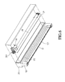
- Figure 6 shows a third embodiment of the window assembly of the present invention, wherein a base 20 is connected to a top of the frame 10 and a motor 26 and a mandrel 27 are received in the base 20.
- a curtain piece 28 is wrapped around the mandrel 27.
- a pulley is connected to an end of the mandrel 27 and a belt 261 reeves through the pulley and an output shaft of the motor 26.
- a slot 115 defined in a lower side of the frame 10 and communicating with the gap 121. A leading edge of the curtain piece 28 is inserted in the slot 115.
Abstract
A window assembly includes two pieces of glass engaged in the window
frame and a base is connected to the window frame. A reservoir and a pump are
received in the base and a liquid with desired color is received in the reservoir. The
liquid is pumped in the gap between the two pieces of glass so as to perform as a
curtain.
Description
- The present invention relates to a window assembly comprising two pieces of glass and a fluid being filled between the glasses to perform as a curtain.
- A conventional window comprises one or two pieces of glass and in order to block the strong brightness outside of the window entering the interior of the room, a curtain is used to reduce the affection of the brightness outside of the room to the people in the room. The conventional curtains although include many types such as blinds and fabric curtain, however, both of the two types of curtains are difficult to be detached from the window frame and to be clean. Besides, to replace or change a new curtain is costly and takes a lot of time. Usually, the users cannot easily to install a new curtain by themselves.
- In accordance with one aspect of the present invention, there is provided a window assembly which comprises a base in which a reservoir for receiving liquid and a pump are received. A first pipe is connected between the reservoir and the pump. A frame has a groove defined in each of four inner sides thereof and two pieces of glass are engaged with the groove of the frame. A gap is defined between the two pieces of glass. An opening is defined in a lower side of the frame and communicates with the gap. A second pipe has an end connected to the pump and the other end of the second pipe is engaged with the opening.
- The primary object of the present invention is to provide a window assembly wherein a liquid with desired color can be filled a gap between two pieces of glass so as to be used as a curtain.
- The present invention will become more obvious from the following description when taken in connection with the accompanying drawings which show, for purposes of illustration only, a preferred embodiment in accordance with the present invention.
-
- Fig. 1 is an exploded view to show a first embodiment of the window assembly of the present invention;
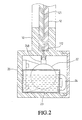
- Fig. 2 is a cross sectional view to show the window assembly of the present invention wherein the liquid is not yet pumped into the gap between the two pieces of glass;
- Fig. 3 is a cross sectional view to show the window assembly of the present invention wherein the liquid is pumped into the gap between the two pieces of glass;
- Fig. 4 is a perspective view to show that the liquid is filled in the gap of the window assembly of the present invention;
- Fig. 5 is an exploded view to show a second embodiment of the window assembly of the present invention, and
- Fig. 6 is an exploded view to show a third embodiment of the window assembly of the present invention.
-
- Referring to Figs. 1 and 2, the window assembly of the present invention comprises a
base 20 and aframe 10 connected on a top of thebase 20. Areservoir 23 for receiving liquid and apump 22 are received in thebase 20. The liquid may have a desired color. Afirst pipe 24 is connected between thereservoir 23 and thepump 22. - The
frame 10 has four inner sides and agroove 11 is defined in each of the inner sides and two pieces ofglass 12 are engaged with thegrooves 11 of theframe 10. Agap 121 is defined between the two pieces ofglass 12 and sealed between theframe 10. Anopening 112 is defined in a lower side of theframe 10 and communicates with thegap 121. Asecond pipe 240 has an end connected to thepump 22 and the other end of thesecond pipe 240 is engaged with theopening 112. - Referring to Figs. 3 and 4, when the
pump 20 is activated by a proper switch or control device, the liquid in thereservoir 23 is pumped into thegap 121 via theopening 112 so that the interior is blocked from being seen from outside by the liquid. - Figure 5 shows a second embodiment of the present invention and is similar to that of the window assembly as shown in Figs. 1-4 except that an
inlet 113 and anoutlet 114 are respectively defined in the lower side of theframe 10 and communicate with thegap 121 between the two pieces ofglass 12. - A
first pipe 25 is connected between thereservoir 23 and thepump 22, and asecond pipe 251 has an end connected to thepump 22 and the other end of thesecond pipe 251 is engaged with theinlet 113. Athird pipe 252 has an end connected to thereservoir 23 and the other end of thethird pipe 252 is engaged with theoutlet 114. By the arrangement. The liquid can be filled into thegap 121 or removed from thegap 121 within a short period of time via theinlet 113 and theoutlet 114. - Figure 6 shows a third embodiment of the window assembly of the present invention, wherein a
base 20 is connected to a top of theframe 10 and amotor 26 and amandrel 27 are received in thebase 20. Acurtain piece 28 is wrapped around themandrel 27. A pulley is connected to an end of themandrel 27 and abelt 261 reeves through the pulley and an output shaft of themotor 26. Aslot 115 defined in a lower side of theframe 10 and communicating with thegap 121. A leading edge of thecurtain piece 28 is inserted in theslot 115. When themotor 26 is activated, themandrel 27 is rotated by thebelt 261 and thecurtain piece 28 is lowered into thegap 121 so as to perform as a curtain. - While we have shown and described the embodiment in accordance with the present invention, it should be clear to those skilled in the art that further embodiments may be made without departing from the scope of the present invention.
Claims (3)
- A window assembly comprising:a base in which a reservoir for receiving liquid and a pump are received, a first pipe connected between the reservoir and the pump, anda frame having multiple inner sides and a groove defined in each of the inner sides thereof and two pieces of glass engaged with the grooves of the frame, a gap defined between the two pieces of glass, an opening defined in a lower side of the frame and communicating with the gap, a second pipe having an end connected to the pump and the other end of the second pipe engaged with the opening.
- A window assembly comprising:a base in which a reservoir for receiving liquid and a pump are received, a first pipe connected between the reservoir and the pump, anda frame having multiple inner sides and a groove defined in each of the inner sides thereof and two pieces of glass engaged with the grooves of the frame, a gap defined between the two pieces of glass, an inlet and an outlet respectively defined in a lower side of the frame and communicating with the gap, a second pipe having an end connected to the pump and the other end of the second pipe engaged with the inlet, a third pipe having an end connected to the reservoir and the other end of the third pipe engaged with the outlet.
- A window assembly comprising:a base in which a motor and a mandrel are received, a curtain piece wrapped around the mandrel, a pulley connected to an end of the mandrel and a belt reeving through the pulley and an output shaft of the motor;a frame connected to a lower side of the base and having multiple inner sides and a groove defined in each of the inner sides thereof and two pieces of glass engaged with the grooves of the frame, a gap defined between the two pieces of glass, a slot defined in a lower side of the frame and communicating with the gap, a leading edge of the curtain piece inserted in the slot.
Priority Applications (1)
| Application Number | Priority Date | Filing Date | Title |
|---|---|---|---|
| EP02012045A EP1367210A1 (en) | 2002-05-31 | 2002-05-31 | Window assembly with fluid between two panes of glass |
Applications Claiming Priority (1)
| Application Number | Priority Date | Filing Date | Title |
|---|---|---|---|
| EP02012045A EP1367210A1 (en) | 2002-05-31 | 2002-05-31 | Window assembly with fluid between two panes of glass |
Publications (1)
| Publication Number | Publication Date |
|---|---|
| EP1367210A1 true EP1367210A1 (en) | 2003-12-03 |
Family
ID=29414734
Family Applications (1)
| Application Number | Title | Priority Date | Filing Date |
|---|---|---|---|
| EP02012045A Withdrawn EP1367210A1 (en) | 2002-05-31 | 2002-05-31 | Window assembly with fluid between two panes of glass |
Country Status (1)
| Country | Link |
|---|---|
| EP (1) | EP1367210A1 (en) |
Cited By (5)
| Publication number | Priority date | Publication date | Assignee | Title |
|---|---|---|---|---|
| WO2007097498A1 (en) * | 2006-02-21 | 2007-08-30 | Seung Jong Shin | Color windows and doors apparatus |
| WO2008102031A1 (en) | 2007-02-23 | 2008-08-28 | Universidad Politecnica De Madrid | Active transparent or translucent enclosures with energy control capacity |
| ITBG20080063A1 (en) * | 2008-12-18 | 2010-06-19 | Capoferri Serramenti S R L | REFRESHING SYSTEM FOR A BUILDING OR INTERNAL ENVIRONMENT |
| ES2400426R1 (en) * | 2011-07-04 | 2013-05-24 | Construcciones Acr S A U | INDUSTRIALIZED AUTOPORTING ENERGY USE SYSTEM FOR BUILDINGS |
| CN112814537A (en) * | 2021-03-11 | 2021-05-18 | 青海平兴建设集团有限公司 | Energy-conserving door and window of aluminum alloy with sunshade function |
Citations (5)
| Publication number | Priority date | Publication date | Assignee | Title |
|---|---|---|---|---|
| DE2314013A1 (en) * | 1972-03-27 | 1973-10-18 | Thorsten Lundberg | INSULATING GLASS WITH LIGHT SHIELD |
| FR2198046A1 (en) * | 1972-08-31 | 1974-03-29 | Rocher Augustin | |
| US4521077A (en) * | 1983-08-16 | 1985-06-04 | The United States Of America As Represented By The Administrator Of The National Aeronautics & Space Administration | Light transmitting window assembly |
| DE4325119A1 (en) * | 1993-07-27 | 1995-02-02 | Wandschneider Ingeborg | Window |
| WO2002010844A2 (en) * | 2000-07-31 | 2002-02-07 | Tuvya Eliyahu | Ornamental panel |
-
2002
- 2002-05-31 EP EP02012045A patent/EP1367210A1/en not_active Withdrawn
Patent Citations (5)
| Publication number | Priority date | Publication date | Assignee | Title |
|---|---|---|---|---|
| DE2314013A1 (en) * | 1972-03-27 | 1973-10-18 | Thorsten Lundberg | INSULATING GLASS WITH LIGHT SHIELD |
| FR2198046A1 (en) * | 1972-08-31 | 1974-03-29 | Rocher Augustin | |
| US4521077A (en) * | 1983-08-16 | 1985-06-04 | The United States Of America As Represented By The Administrator Of The National Aeronautics & Space Administration | Light transmitting window assembly |
| DE4325119A1 (en) * | 1993-07-27 | 1995-02-02 | Wandschneider Ingeborg | Window |
| WO2002010844A2 (en) * | 2000-07-31 | 2002-02-07 | Tuvya Eliyahu | Ornamental panel |
Cited By (8)
| Publication number | Priority date | Publication date | Assignee | Title |
|---|---|---|---|---|
| WO2007097498A1 (en) * | 2006-02-21 | 2007-08-30 | Seung Jong Shin | Color windows and doors apparatus |
| WO2008102031A1 (en) | 2007-02-23 | 2008-08-28 | Universidad Politecnica De Madrid | Active transparent or translucent enclosures with energy control capacity |
| ES2304871A1 (en) * | 2007-02-23 | 2008-10-16 | Universidad Politecnica De Madrid | Active transparent or translucent enclosures with energy control capacity |
| ES2304871B2 (en) * | 2007-02-23 | 2010-01-29 | Universidad Politecnica De Madrid | TRANSPARENT CLOSURES OR ACTIVE TRANSLUCED WITH A CAPACITY OF ENERGY GE STION. |
| US8341894B2 (en) | 2007-02-23 | 2013-01-01 | Universidad Politecnica De Madrid | Active transparent or translucent enclosures with energy control capacity |
| ITBG20080063A1 (en) * | 2008-12-18 | 2010-06-19 | Capoferri Serramenti S R L | REFRESHING SYSTEM FOR A BUILDING OR INTERNAL ENVIRONMENT |
| ES2400426R1 (en) * | 2011-07-04 | 2013-05-24 | Construcciones Acr S A U | INDUSTRIALIZED AUTOPORTING ENERGY USE SYSTEM FOR BUILDINGS |
| CN112814537A (en) * | 2021-03-11 | 2021-05-18 | 青海平兴建设集团有限公司 | Energy-conserving door and window of aluminum alloy with sunshade function |
Similar Documents
| Publication | Publication Date | Title |
|---|---|---|
| US7000670B2 (en) | Blind and methods for operating thereof | |
| CA2229120A1 (en) | Methods of completing a subterranean well and associated apparatus | |
| EP1367210A1 (en) | Window assembly with fluid between two panes of glass | |
| EP0958838A3 (en) | White blood cell-removing device and method | |
| AU2316999A (en) | Manually operated reciprocating liquid pump with sealing vent opening | |
| EP1807598B1 (en) | Supporting means facilitating the installation of a screening device, and a window for cooperation with the supporting means | |
| US20190019391A1 (en) | Safety Handrail Capable of Displaying Suction Force | |
| US4223499A (en) | Decorative stained glass insert unit for windows | |
| US4850416A (en) | Slat shade operator | |
| US20080163570A1 (en) | Glass-Darkening System Which is Suitable For Windows and Similar | |
| CA2240936C (en) | Variable decorative treatment | |
| AU5232099A (en) | Fluid driven pump and portioning check valve | |
| USD425747S (en) | Holder for a venetian blind or ornamental shades | |
| USD442293S1 (en) | J-channel glider frame for double glider window | |
| CN100570120C (en) | Magnetic-type fixedly screen window | |
| USD493651S1 (en) | Window shade | |
| USD498306S1 (en) | Glue chip beveled glass privacy window | |
| USD432678S (en) | J-channel sill for double and single hung window | |
| CN209942572U (en) | Polar frame sliding window | |
| USD432681S (en) | Bendable picture frame with J-channel for picture window | |
| NL2003906C2 (en) | DEVICE FOR AUTOMATICALLY OPERATING A SCREEN, SUCH AS A WINDOW COVER. | |
| USD499596S1 (en) | Window shade | |
| USD509090S1 (en) | Rollable panel | |
| USD509091S1 (en) | Rollable panel | |
| USD507918S1 (en) | Rollable panel |
Legal Events
| Date | Code | Title | Description |
|---|---|---|---|
| PUAI | Public reference made under article 153(3) epc to a published international application that has entered the european phase |
Free format text: ORIGINAL CODE: 0009012 |
|
| AK | Designated contracting states |
Kind code of ref document: A1 Designated state(s): AT BE CH CY DE DK ES FI FR GB GR IE IT LI LU MC NL PT SE TR |
|
| AX | Request for extension of the european patent |
Extension state: AL LT LV MK RO SI |
|
| AKX | Designation fees paid | ||
| REG | Reference to a national code |
Ref country code: DE Ref legal event code: 8566 |
|
| STAA | Information on the status of an ep patent application or granted ep patent |
Free format text: STATUS: THE APPLICATION IS DEEMED TO BE WITHDRAWN |
|
| 18D | Application deemed to be withdrawn |
Effective date: 20040604 |